


ORTHOPANTOMOGRAPH

ORTHOPANTOMOGRAPH™ OP 3D Pro
3D Dental X-Ray System
Installation Manual
ENGLISH
216363 rev. 1
0.805.5080


Copyright Copyright © 2017 by PaloDEx Group Oy.
All rights reserved.
ORTHOPANTOMOGRAPH™ and CLINIVIEW™ are either
registered trademarks or trademarks of PaloDEx Group Oy
in the United States and/or other countries.
KaVo™ and EasyScout™ are either registered trademarks
or trademarks of Kaltenbach & Voigt GmbH in the United
States and/or other countries.
All other trademarks are property of their respective
owners.
Documentation, trademark and the software are
copyrighted with all rights reserved. Under the copyright
laws the documentation may not be copied, photocopied,
reproduced, translated, or reduced to any electronic
medium or machine readable form in whole or part, without
the prior written permission of PaloDEx Group Oy.
The original language of this manual is English.
PaloDEx Group Oy reserves the right to make changes in
specification and features shown herein, or discontinue the
product described at any time without notice or obligation.
Contact your PaloDEx Group Oy representative for the
most current information.
Manufacturer Instrumentarium Dental, PaloDEx Group Oy
Nahkelantie 160
FI-04300 Tuusula
FINLAND
Tel. +358 10 270 2000
www.kavokerrgroup.com
For service, contact your local distributor.


rev i
Table of Contents
1 Introduction..................................................................................................................1
1.1 ORTHOPANTOMOGRAPH™ OP 3D Pro ............................................................1
1.2 Intended use .........................................................................................................2
1.3 Associated documentation....................................................................................2
1.4 References............................................................................................................2
1.5 Abbreviations used in this manual ........................................................................3
1.6 Warnings and precautions ....................................................................................4
1.6.1 Warnings for cross infection. ......................................................................4
1.6.2 Warnings to be observed during installation and service...........................4
1.6.3 Cautions for Electrostatic discharge...........................................................6
1.6.4 General warnings.......................................................................................6
1.7 Disclaimer .............................................................................................................9
1.8 Disposal ................................................................................................................9
2 Unit description .........................................................................................................11
2.1 Main parts and controls.......................................................................................11
2.2 Patient positioning lights .....................................................................................13
2.3 Patient positioning panel.....................................................................................17
2.3.1 Cephalometric unit positioning panel.......................................................17
2.4 Main control panel...............................................................................................18
2.5 Unit identification labels ......................................................................................19
2.6 Unit movements..................................................................................................20
2.7 Emergency stop switch.......................................................................................21
3 Pre-installation requirements...................................................................................23
3.1 The unit...............................................................................................................23
3.2 Space requirements............................................................................................25
3.3 Fixing hardware and Installation and Setup tools ...............................................26
4 PC requirements........................................................................................................27
4.1 Minimum PC requirements..................................................................................27
4.2 The dental imaging software...............................................................................29
5 Installing the unit.......................................................................................................31
5.1 Content of delivery..............................................................................................31
5.2 The column .........................................................................................................31
5.3 The carriage........................................................................................................37
5.4 Check leveling.....................................................................................................42
5.5 Installing additional set screws and connecting cables.......................................43
5.6 Attaching the touch screen display to the column (new model)..........................45
5.7 Exposure button..................................................................................................47
5.8 External warning light (optional)..........................................................................48
5.9 Installing the cephalometric unit..........................................................................49
5.9.1 Enabling carpus imaging..........................................................................60

ii rev
6 Panoramic and 3D calibrations and adjustments...................................................61
6.1 Introduction .........................................................................................................61
6.2 When to calibrate the unit ...................................................................................62
6.3 Reset maintenance counter................................................................................63
6.4 Preparing for calibration......................................................................................63
6.5 The calibration sequence....................................................................................66
6.5.1 Calibration of the preheat of the tube.......................................................66
6.5.2 Calibration of the tube current..................................................................66
6.5.3 3D collimator calibration...........................................................................67
6.5.4 3D Beam size verification (optional).........................................................69
6.5.5 Panoramic collimator calibration..............................................................70
6.5.6 Panoramic geometry calibration...............................................................74
6.5.7 3D geometry calibration...........................................................................75
6.5.8 SFOV (Small panel) 3D lasers alignment ................................................76
6.5.9 MFOV (Medium panel) 3D lasers alignment............................................78
6.5.10 Panoramic laser alignment.......................................................................82
6.5.11 3D pixel calibration...................................................................................84
6.5.12 Panoramic pixel calibration......................................................................84
6.5.13 3D Quality Check ....................................................................................85
6.5.14 Panoramic Quality Check (optional).........................................................90
7 Cephalometric calibration and alignment...............................................................93
7.1 Preparations........................................................................................................93
7.2 Cephalometric calibration sequence...................................................................93
7.2.1 Balancing the cephalostat........................................................................94
7.2.2 Primary collimator calibration...................................................................94
7.2.3 Rotation angle calibration.........................................................................95
7.2.4 Mechanical adjustment program..............................................................97
7.2.5 Secondary collimator horizontal adjustment ..........................................108
7.2.6 Cephalostat laser alignment...................................................................110
7.2.7 Cephalostat pixel calibration..................................................................111
7.2.8 Cephalostat Quality Check (optional).....................................................111
7.2.9 Ear holder alignment..............................................................................113
7.2.10 Horizontal adjustment ............................................................................115
7.2.11 Vertical adjustment.................................................................................116
8 Special procedures..................................................................................................117
8.1 General .............................................................................................................117
8.2 Cephalometric upgrade kit................................................................................117
8.3 Changing the cephalostat arm side...................................................................117
8.4 Changing the cephalostat arm side in service mode ........................................126
8.5 Adjusting and calibrating the cephalostat..........................................................127
8.6 Connecting the unit to the mains.......................................................................128
8.6.1 Preparing the PC....................................................................................131
8.6.2 Configuring the communication link to the PC.......................................131
8.7 Firmware update...............................................................................................133
8.7.1 Preparing for update ..............................................................................133
8.7.2 Software update.....................................................................................134
8.7.2.1 Automatic update.....................................................................134
8.7.2.2 Manual update.........................................................................134
8.8 Volatile installation ............................................................................................138

rev iii
8.8.1 Installation procedure.............................................................................139
8.9 Special cases....................................................................................................142
8.9.1 Programming a R3220 Main CPU board having wrong unit
type configured.......................................................................................142
8.9.2 Programming a non-responsive cephalostat CPU.................................143
8.10 Troubleshooting ................................................................................................147
8.10.1 Problem: No connection to the X-ray unit / R3220 circuit board............147
8.10.2 Problem: Automatic software update fails..............................................148
8.10.3 Problem: Manual update fails.................................................................148
8.10.4 Problem: S2terminal is unable to find binary files..................................148
8.11 Configurable panoramic mAs limit ....................................................................149
9 OP 3D Pro Pre-sales check list...............................................................................151
9.1 Physical Environment Requirements................................................................151
9.2 Radiation Shielding Requirements....................................................................151
9.3 Mechanical Specifications ................................................................................152
9.4 Electrical Specifications ....................................................................................152
9.5 Networking Specifications.................................................................................153
9.6 Computer Specifications...................................................................................154
9.7 Backup Specifications.......................................................................................154
9.8 DICOM Services SCP.......................................................................................154
9.9 Software configuration ......................................................................................155
9.10 Other information ..............................................................................................156
9.11 Notes / comments.............................................................................................157
9.12 Dimensions .......................................................................................................158
9.13 Dimensions with cephalostat.............................................................................159

iv rev

1 Introduction
1
1 Introduction
1.1 ORTHOPANTOMOGRAPH™ OP 3D Pro
ORTHOPANTOMOGRAPH™ OP 3D Pro is a dental X-ray
system for producing high quality digital images of
dentition, TM-joints and skull. In order to take images with
OP 3D Pro you need a suitable PC hardware connected to
the OP 3D Pro unit and CLINIVIEW™
imaging software to
capture and manage images. The OP300 performs the
following procedures:
Panoramic
• Standard panoramic
• Pediatric panoramic
• Wide arch panoramic
• Bitewing
• TMJ, posterior-anterior (PA) projection
• TMJ, lateral projection (axially corrected)
• Ortho TMJ, axial corrected lateral projection
• Maxillary sinus
• Ortho Zone enhanced panoramic
• Orthogonal panoramic
Cephalometric (optional)
• Cephalometric lateral projection
• Cephalometric pediatric lateral projection
• Cephalometric postero-anterior (PA) projection
• Reverse Towne projection
• Waters view
• Carpus program (optional) (Not available in USA
and Canada)
3D Small panel (optional) H x W
• 61 x 41 mm Field of View
• 61 x 78 mm Field of View

2
3D Medium panel, H x W (optional)
• 50 x 50 mm Field of View
• 61 x 78 mm Field of View
• 78 x 78 mm Field of View
• 78 x 150 mm Field of View
• 130 x 150 mm Field of View (optional)
NOTICE! The FOV heights are maximum values measured
at the center of the FOV, the measured heights at the
edges of the FOV are smaller.
1.2 Intended use
The unit is intended for dental radiographic examination of
teeth, jaw and TMJ areas by producing conventional 2D x-
ray images as well as x-ray projection images of an
examined volume for the reconstruction of a 3D view.
The unit is also intended for carpus imaging in assisting
cephalometric analyses (Not in USA).
CAUTION! USA only: Federal law restricts this device to
sale by or on the order of a dentist or other qualified
professional.
1.3 Associated documentation
• OP 3D Pro User manual
• OP 3D Pro Service manual
• CLINIVIEW software user manual
• CLINIVIEW software installation manual
• The user manual supplied with the 3D imaging
software
• The installation manual supplied with the 3D
imaging software
1.4 References
The following instructions are delivered with in the
OP 3D Pro installation manual:
• Firmware update instructions

1 Introduction
3
• Calibration instructions
• Cephalostat upgrade instructions
• Cephalostat side changing instructions
1.5 Abbreviations used in this manual
FOV = Field Of View. The cylindrical 3D volume that is
reconstructed by the system.
ROI = Region Of Interest. The anatomical area or region of
the patient that you are interested to examine.
FH = Frankfort-Horizontal
H = Horizontal
ADC = Automatic Dose Control
LDT = Low Dose Technology™
MAR = Metal Artifact Reduction

1 Introduction
4
1.6 Warnings and precautions
1.6.1 Warnings for cross infection
1.6.2 Warnings to be observed during
installation and service
Always use available disposable protective covers with the
patient positioning accessories:
• Bite fork cover
• Chin support cover
• Head support cover
• Nose support cover
• Ear holder cover
In case the transportation package has been damaged,
make sure the actual product is fully intact.
Before attempting to service the device make sure that you
know how to operate it. Read the user’s manual.
Read and familiarize yourself with the warnings and precau-
tions listed in the user’s manual.
Only use original spare parts from the manufacturer when
repairing the device or replacing parts.
Warning - Radiation Safety
Before servicing the unit familiarize yourself with local and
national radiation safety standards and requirements relat-
ing to dental x-ray equipment.
Warning - Electrical Safety
Disconnect the unit from the main power supply before re-
moving any covers.
Disconnect the unit from the main power supply before re-
pairing or replacing mechanical parts or installing accesso-
ries.
Be careful when operating the unit not to get body parts or
clothing trapped between moving parts.
Disconnect the unit from the mains power connection be-
fore servicing the unit, e.g. replacing circuit boards or other
electrical components.
If there are capacitors on a circuit board or electrical device
wait ten (10) minutes, after disconnecting the unit from the
power supply, before handling the board or device.

1 Introduction
5
If you have to leave the unit unattended with covers re-
moved during servicing or maintenance, disconnect the unit
from main power supply so that anyone who inadvertantly
touches the unit does not receive an electric shock.
This unit should only be used in areas that are provided with
a protective earth connection to ensure an equipotential
ground connection.
Warning - Explosion hazard
Some disinfectants and cleaning agents may vaporize to
form an explosive vapour. If such disinfectants and cleaning
agents are used the vapour should be allowed to disperse
before switching the unit on.
Warning - Cleaning the unit
Switch the unit off and disconnect it from the main power
supply before cleaning or disinfecting the unit.
The aperture plate and the tube housing are made of lead
(Pb), which is a toxic material. Do not touch it with your bare
hands.
The installer must ensure that:
- The fixing screws are suitable for the wall material.
- The wall for fixing the unit is strong enough for attaching
the unit. It must withstand loads of 5000N or more.
- Pull out strength of the screws is 5000N or more.
- The wall fixing screws are adequately tightened.
To avoid the unit from tipping over, fix the unit with floor
bolts appropriate to the surface the unit is mounted on. The
bolts and the floor material must endure force of 5000 N.
The installer must ensure that the upper shelf attachment
screws are tightened.
The unit should be installed in a place with enough space
for safe operation. See the unit installation manual for rec-
ommended minimum site dimensions. It is the responsibility
of the customer to ensure that the site is large enough for
the patients.
Be aware of hot surfaces when removing covers during in-
stallation and maintenance.
When installing a dental X-ray unit always observe local and
national safety, radiation control and electrical regulations.

1 Introduction
6
1.6.3 Cautions for Electrostatic discharge
1.6.4 General warnings
Electrostatic Discharge (ESD) can damage or destroy elec-
tronic components.
When servicing the device take precautions to avoid elec-
trostatic build up and discharge (ESD). Follow the recom-
mendations for the prevention of ESD that are used in the
country in which you are working. If no recommendations
are available follow the guide lines below.
Leave all new or replacement circuit boards and electrical
parts in their protective packaging until the boards are
needed.
Before handling circuit boards and electrical parts make
sure that any static electricity charge that has built up in you
body is discharged.
When handling circuit boards hold them by their edges and
do not touch any connectors or components.
When examining and checking circuit boards use an elasti-
cated wrist wrap which is connected to a ground point
through a 1 Mohm current limiting cable. For a ground point
use water pipes, radiators or other objects that are known
to be connected to the ground. Also use a cable to connect
the x-ray unit to the same ground potential as the wrist
wrap.
If an antistatic mat is used, connect the wrist wrap to the mat
and the mat to the ground potential.
Wash the wrist wrap and check that it is in good condition
frequently.
Personnel operating the device must be adequately trained
with respect to the technological principles of operation and
radiation protection when using cone beam computed
tomography (CBCT) imaging.
This unit complies with the EMC (Electromagnetic
Compatibility) according to IEC 60601-1-2. Radio
transmitting equipment, cellular phones etc. shall not be
used in close proximity of the unit as they could influence
the performance of the unit.

1 Introduction
7
Always ensure to fulfill the requirements of the local and na-
tional regulations.
The correct software and settings in the workstation are
essential to the performance of the unit. Consult technical
support to ensure correct setup.
Danger - Explosion hazard
Do not use in the presence of flammable anesthetics, gases or
vapors.
The unit is factory set to operate using a 230-240 ±10 VAC
power supply. Never connect the unit to a power supply
different to the voltage marked on the unit.
If the unit needs to be connected to a multiple socket-outlet,
the socket shall not be placed on the floor.
To avoid the risk of electric shock, the unit must only be
connected to a supply mains with protective earth.
The site must fulfill the environmental requirements in the
installation manual chapter technical specifications.
There should be free space around the unit for safe
operation.
The PC / Ethernet switch to which the unit is connected,
should be approved appropriately (e.g. EN 60950, IEC
60950, UL 60950). After installation, check that the IEC
60601-1 leakage current levels are not exceeded.
This product itself complies with IEC 60601-1 medical
safety standard but in order to the system incorporating also
a PC to comply the standard, EITHER the PC has to be a
medical PC OR the PC has to be located over 1,5 meters
apart from the unit. The installer and the user of the system
shall confirm that at least one of the above requirements is
fulfilled. A PC is a medical one if it complies IEC 60601-1
standard and that is indicated in the accompanying
documents of the PC.
The unit shall be connected directly to the acquisition PC
with an Ethernet cable. Connection through the LAN-net-
work of the site is not allowed. Two network ports are
needed in the PC in order to connect also to the site
network.
All service operations must be made by authorized service
personnel only.
The annual service as described in manual is mandatory for
the correct and safe operation of the unit.

1 Introduction
8
When taking exposures, operators and service personnel
must protect themselves from radiation and remain at least
two meters (six feet) away from the unit during exposure.
Protect the patient from scattered radiation by placing a
protective lead apron over the patient.
The unit must be installed and serviced according to the unit
Installation & adjustments manual by a qualified technician.
Only personnel trained and approved by the manufacturer
of the unit are allowed to service the unit.
3D imaging should not be used for routine or screening
examinations in which a radiograph is taken regardless of
the presence or absence of clinical signs and symptoms. 3D
imaging examinations must be justified for each patient to
demonstrate that the benefits outweigh the risks.
Where it is likely that evaluation of soft tissues will be
required as part of the patient’s radiological assessment,
the imaging should be done using conventional medical CT
or MR, rather than 3D imaging using Cone Beam
technology.
Cone beam computed tomography images are not
adequate for the analysis of soft tissue.
Panoramic and 3D exposures should not be used if
conventional intraoral radiographic images (like bitewing
exposures) would be sufficient.
Make sure that patient’s thyroid glands are protected by a
lead apron during the exposure.
The place where the unit is to be installed and the position
from where the user will take exposures must be correctly
shielded from the radiation that is generated when the unit
is operated. Ensure to fulfill or exceed the requirements of
your local regulations.
The unit or its parts must not be changed or modified in any
way without approval and instructions from the
manufacturer.
When servicing use only approved replacement parts
supplied by the manufacturer.
The use of accessories not complying with the equivalent
safety requirements of this equipment may lead to a
reduced level of safety of the resulting system.

1 Introduction
9
1.7 Disclaimer
The manufacturer shall have no liability for consequential
damages, personal injury, loss, damage or expense
directly or indirectly arising from the use of its products. No
agent, distributor or other party is authorized to make any
warranty or other liability on behalf of the manufacturer with
respect to its products.
1.8 Disposal
The device, its spare parts, its replacement parts and its
accessories may include parts that are made of or include
materials that are non-environmentally friendly or
hazardous. These parts must be disposed of in
accordance with all local, national and international
regulations regarding the disposal of non-environmentally
friendly or hazardous materials.
Unit has at least the following parts that should be
regarded as non-environmental friendly waste products:
■ Tubehead (Pb, oil)
■ Collimator (Pb)
■ All electronic circuits, electronic boards inside
■ Sensor covers (EMC painted)
If this device is used with 3rd party imaging application
software not supplied by the manufacturer, the 3rd party
imaging application software must comply with all local laws
on patient information software. This includes the Medical
Device Directive 93/42/EEC and/or relevant legal
requirements in the USA.
Do not connect any equipment to the unit that has not been
supplied with the unit or that is not recommended by the
manufacturer. The use of accessory equipment not
complying with the equivalent safety requirements of this
equipment may lead to a reduced level of safety of the
resulting system.
All protective covers must be properly installed before
handing unit to the user or when operating the unit.

1 Introduction
10
2 Unit description
11
2 Unit description
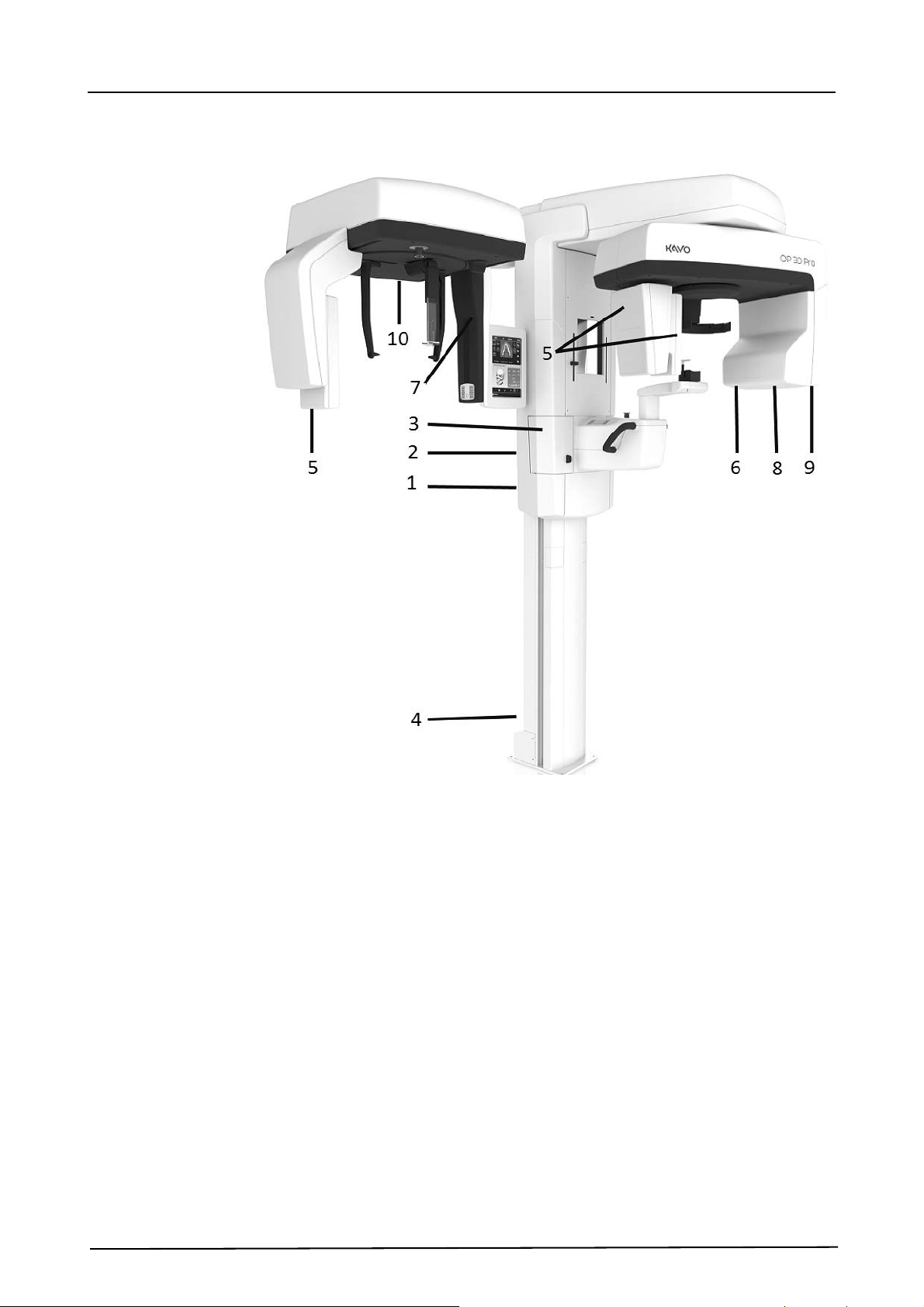
2.1 Main parts and controls
PC with MDD approved dental imaging software and 3D
viewing software (not included).
All software must conform to the MDD and the relevant
legal requirements in the USA.
The PC must conform to all the unit and dental imaging
software requirements.
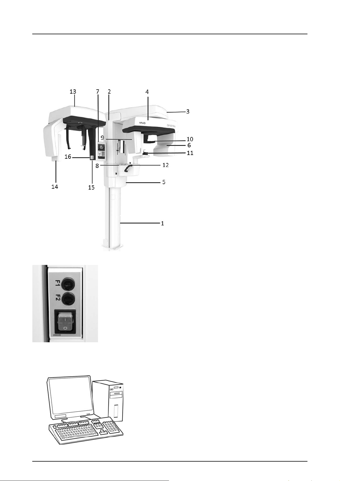
1. Column
2. Carriage
3. Main support
4. Rotating unit
5. On/off switch (rear of carriage)
and main fuses
6. Tubehead assembly
7. Touch screen display
8. Patient positioning panel
9. Sensor head
10.Head support
11.Chin rest
12.Handles
13.Cephalostat unit
14.Cephalostat sensor
15.Secondary collimator
16.Patient positioning panel
On/off switch (used to power the unit on and off) and
main fuses.
2 Unit description
12
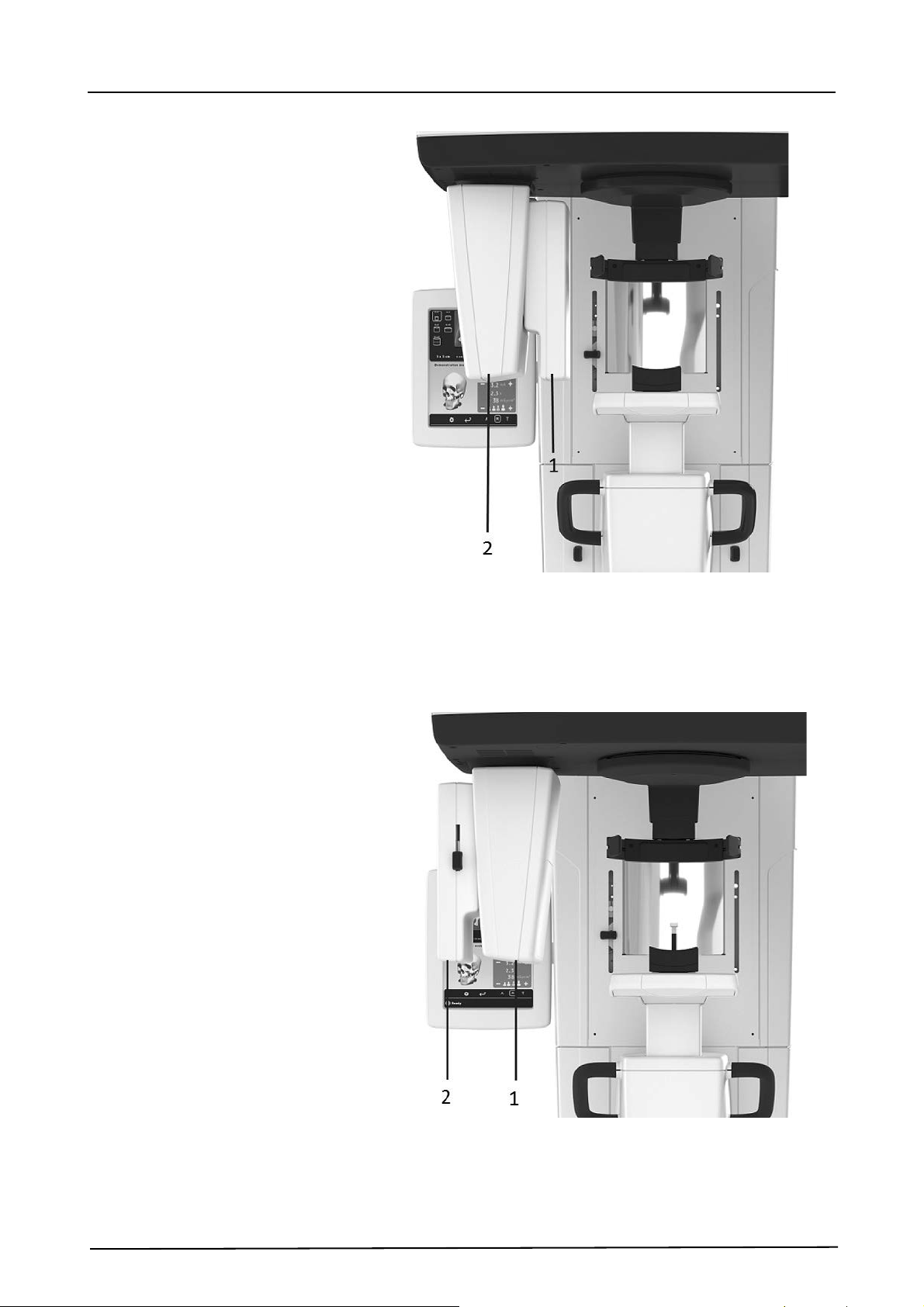
1. Sensor holder (panoramic units without 3D option)
2. Panoramic sensor
1. 3D sensor (units with 3D option)
2. Panoramic sensor
2 Unit description
13
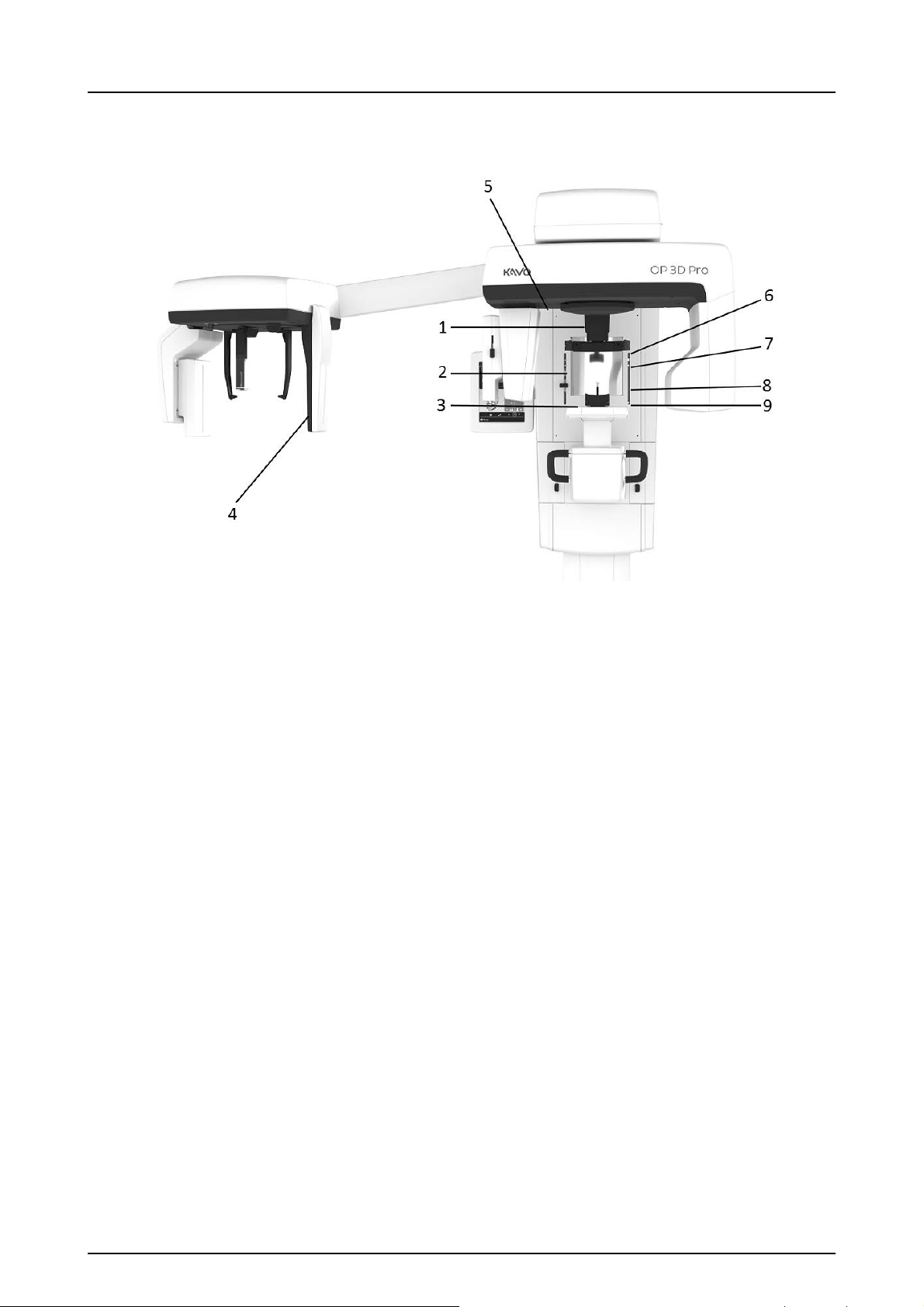
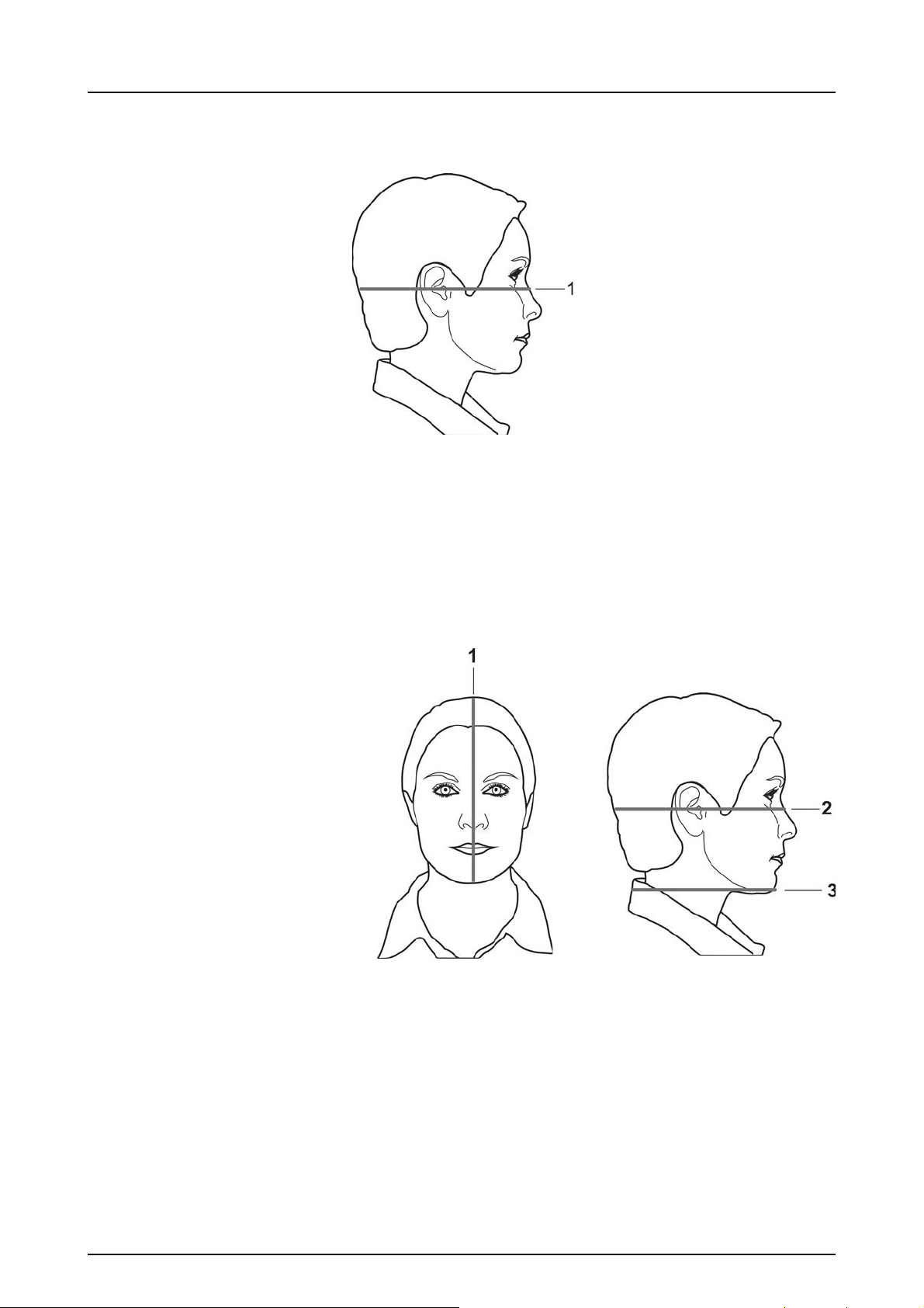
2.2 Patient positioning lights
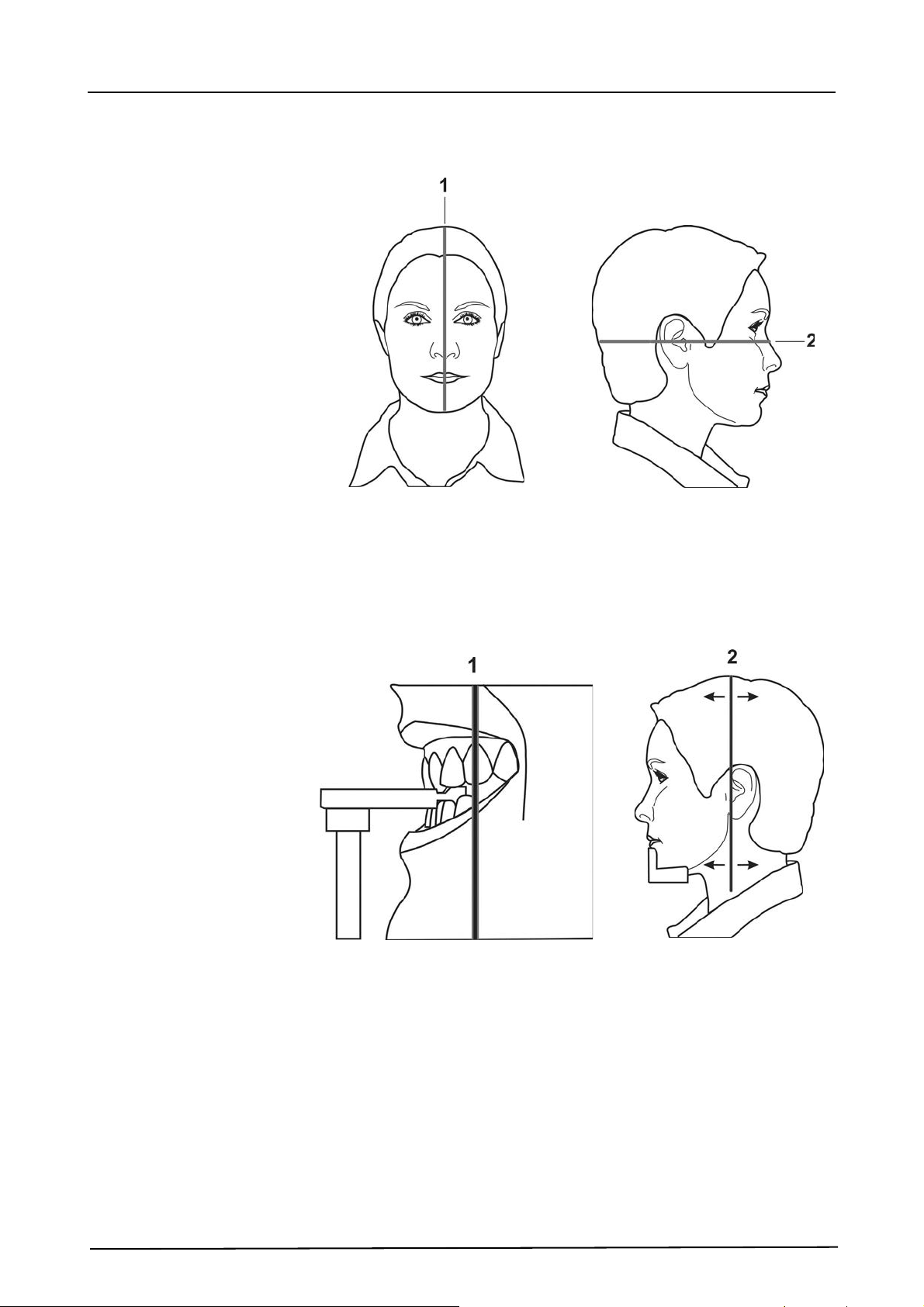
1. Midsagittal light
2. Frankfort horizont al (FH) light /
Horizontal light, top of 130 mm high FOV (Medium Panel
3D option only)
3. Image layer light
4. Cephalometric FH light
5. TMJ light
6. Horizontal light, top of 78 mm high FOV
7. Horizontal light, top of 61 mm high FOV
8. Horizontal light, top of 50 mm FOV
9. Horizontal light, bottom of FOV
2 Unit description
14
Panoramic lights
1. Midsagittal light
2. FH light
1. Image layer
2. TMJ light
2 Unit description
15
Cephalometric lights (optional)
1. FH light
3D lights (optional)
NOTICE! Appropriate lights are turned automatically on
based on selected FOV.
1. Midsagittal light
2. Horizontal light, top of FOV
NOTICE! With Medium Panel 3D option, Optional 130
mm height is indicated with Frankfort horizontal (FH)
light. Move FH light to 130 mm position (locked in up-
position).
3. Horizontal light, bottom of FOV
2 Unit description
16
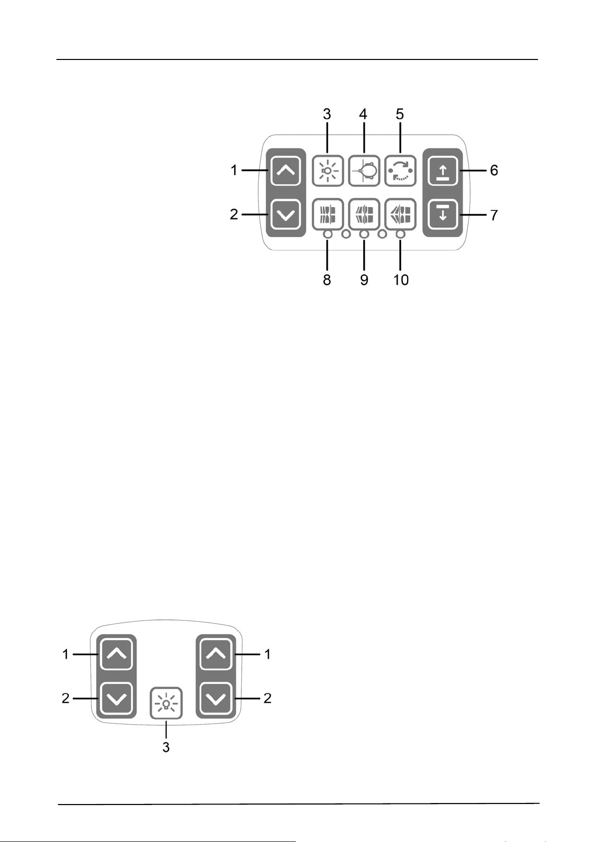
2.3 Patient positioning panel
1. Carriage UP
2. Carriage DOWN
3. Positioning lights ON/OFF
4. Patient positioning
5. Start position
6. Chin support UP
7. Chin support DOWN
8. Move the image layer anterior before exposure 3 mm,
with sinus program 10 mm
9. Normal occlusion/ reset position
10.Move the image layer posterior before exposure 3 mm,
with sinus program 10 mm.
2.3.1 Cephalometric unit positioning panel
1. Carriage UP
2. Carriage DOWN
3. Positioning lights ON/OFF
2 Unit description
17
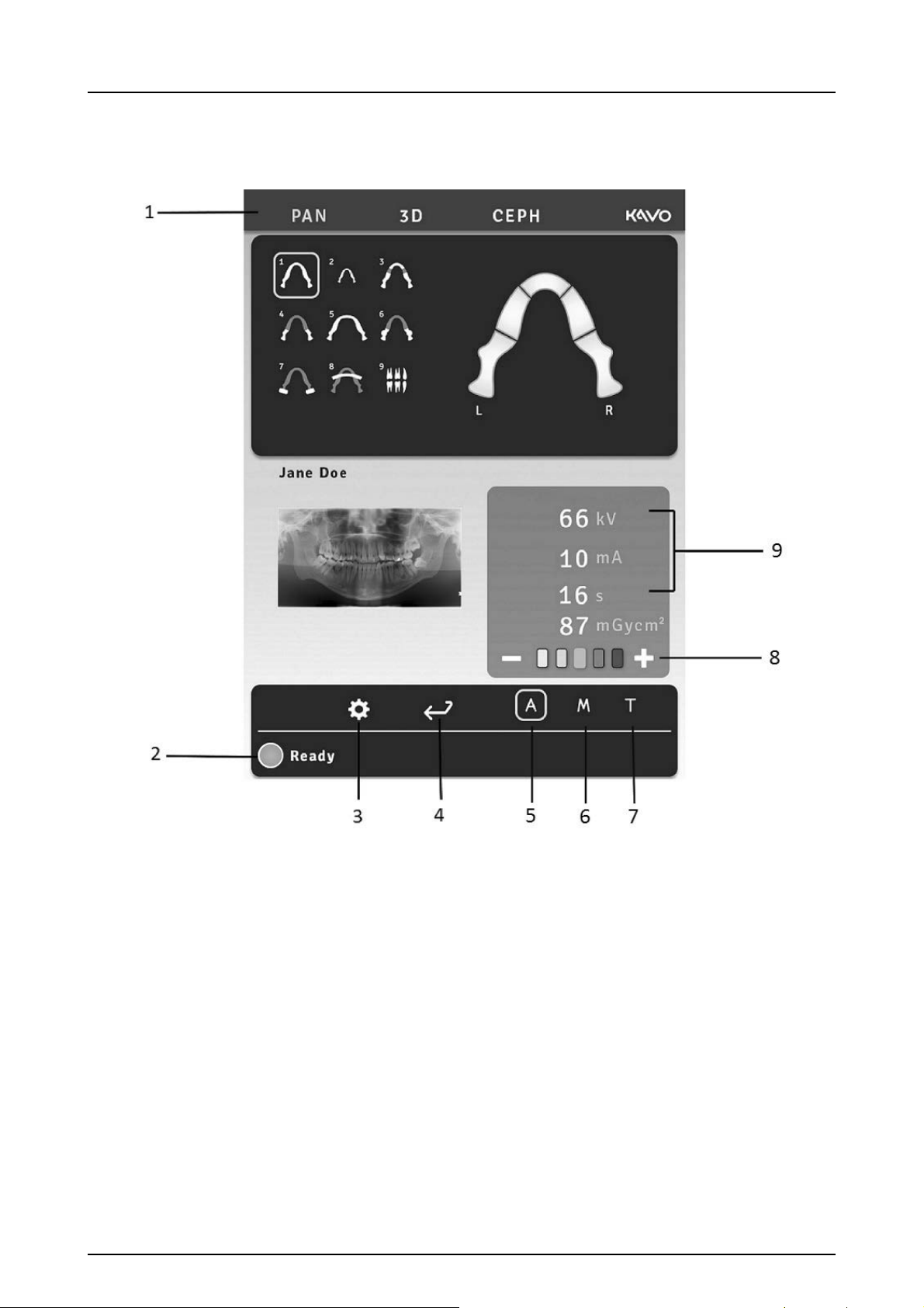
2.4 Main control panel
1. Modality / imaging program section
2. Status of the unit
3. Settings
4. End examination
5. Automatic Dose Control
6. Manual mode
7. Test mode
8. Patient size selection
9. Exposure settings
2 Unit description
18
2.5 Unit identification labels
1. Main label
2. 10A & 15A Fuse labels (next to the fuse holder)
3. Laser class 1 warning label IEC 60825-1:2007
4. Ethernet label
5. Sensors
6. (Primary) collimator label
7. (Secondary) cephalosta t collimator label
8. Tubehead label
(on the tubehead and on the tubehead cover)
9. Warning label for deadly voltages
(inside the tubehead cover)
10.Cephalostat main label
2 Unit description
19
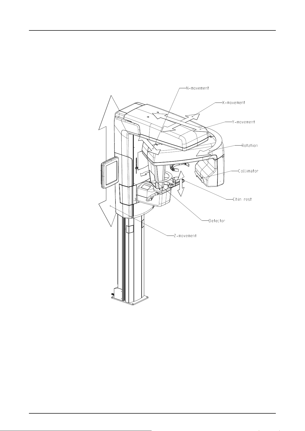
2.6 Unit movements
Panoramic unit movements
(R)
(C)
(J)
(D)
2 Unit description
20
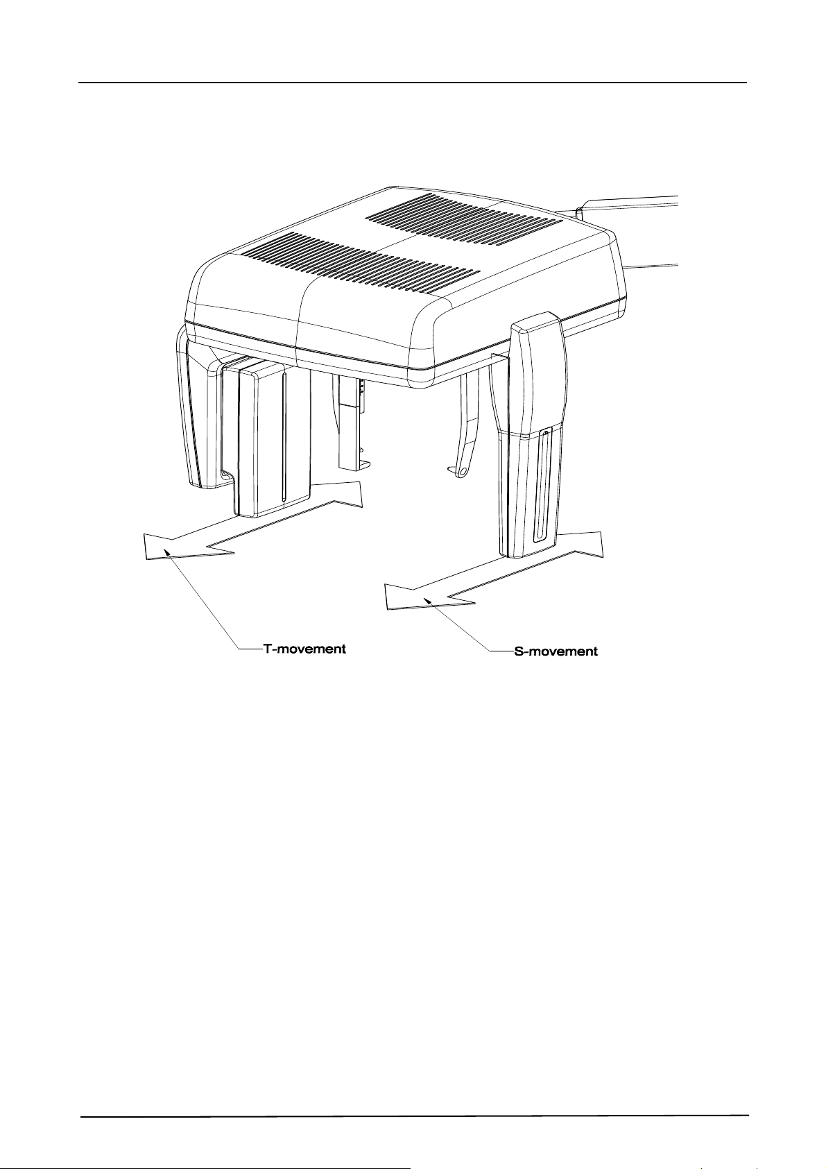
Cephalometric unit movements
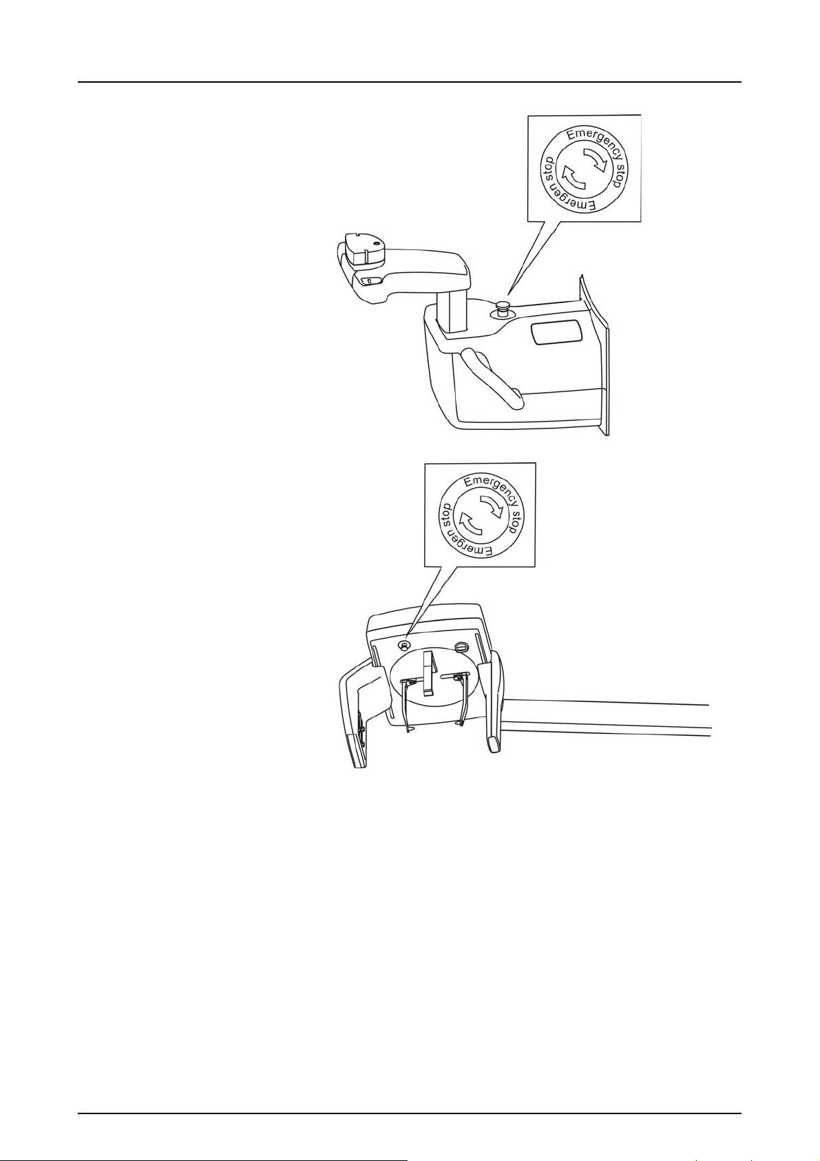
2.7 Emergency stop switch
In case of malfunction of the exposure button or other
protective devices of the unit, an emergency stop switches
are located near the handles and on the cephalostat unit,
so that the patient can easily reach them.
If the emergency stop switch is pressed during an
exposure, the exposure is terminated immediately and the
x-ray unit is completely stopped. An interrupted exposure
cannot be continued later, but has to be retaken from the
beginning after the emergency stop switch is released.
Press to stop the unit, rotate to release.
2 Unit description
21

2 Unit description
22
 Loading...