

Programmable DC Power Supply
PSU Series
USER MANUAL
ISO-9001 CERTIFIED MANUFACTURER
99 Washington Street
Melrose, MA 02176
Phone 781-665-1400
Toll Free 1-800-517-8431
Visit us at www.TestEquipmentDepot.com

This manual contains proprietary information, which is protected by
copyright. All rights are reserved. No part of this manual may be
photocopied, reproduced or translated to another language without
prior written consent of Good Will company.
The information in this manual was correct at the time of printing.
However, Good Will continues to improve products and reserves the
rights to change specification, equipment, and maintenance
procedures at any time without notice.
Good Will Instrument Co., Ltd.
No. 7-1, Jhongsing Rd., Tucheng Dist., New Taipei City 236, Taiwan.

TABLE OF CONTENTS
Table of Contents
SAFETY INSTRUCTIONS .................................................. 5
GETTING STARTED .......................................................... 9
PSU Series Overview ............................ 10
Appearance .......................................... 15
Theory of Operation ............................. 23
OPERATION .................................................................. 35
Set Up .................................................. 37
Basic Operation ................................... 53
Parallel / Series Operation ................... 71
Test Scripts .......................................... 88
CONFIGURATION .......................................................... 96
Configuration Overview ....................... 97
ANALOG CONTROL ...................................................... 121
Analog Remote Control Overview ....... 122
Remote Monitoring ............................ 141
Isolated Analog Control Option ......... 149
COMMUNICATION INTERFACE .................................... 165
Interface Configuration ...................... 166
FAQ .............................................................................. 195
APPENDIX .................................................................... 197
PSU Factory Default Settings ............. 197
Error Messages & Messages .............. 200
LED ASCII Table Character Set ........... 201
PSU Specifications ............................. 202
3

PSU Series User Manual
PSU Dimensions ................................ 210
Declaration of Conformity .................. 211
INDEX .......................................................................... 212
4
SAFETY INSTRUCTIONS
WARNING
Warning: Identifies conditions or practices that
could result in injury or loss of life.
CAUTION
Caution: Identifies conditions or practices that
could result in damage to the PSU or to other
properties.
DANGER High Voltage
Attention Refer to the Manual
Protective Conductor Terminal
Earth (ground) Terminal
SAFETY INSTRUCTIONS
This chapter contains important safety
instructions that you must follow during
operation and storage. Read the following before
any operation to insure your safety and to keep
the instrument in the best possible condition.
Safety Symbols
These safety symbols may appear in this manual or on the
instrument.
5

Do not dispose electronic equipment as unsorted
municipal waste. Please use a separate collection
facility or contact the supplier from which this
instrument was purchased.
Safety Guidelines
General
Guideline
CAUTION
Do not place any heavy object on the PSU.
Avoid severe impact or rough handling that
leads to damaging the PSU.
Do not discharge static electricity to the PSU.
Use only mating connectors, not bare wires, for
the terminals.
Do not block the cooling fan opening.
Do not disassemble the PSU unless you are
qualified.
(Measurement categories) EN61010-1:2010 and EN61010-2-030
specifies the measurement categories and their requirements as
follows. The PSU falls under category II.
Measurement category IV is for measurement performed at the
source of low-voltage installation.
Measurement category III is for measurement performed in the
building installation.
Measurement category II is for measurement performed on the
circuits directly connected to the low voltage installation.
0 is for measurements performed on circuits not directly
connected to Mains.
Power Supply
WARNING
AC Input voltage range: 85Vac~265Vac
Frequency: 47Hz to 63Hz
To avoid electrical shock connect the protective
grounding conductor of the AC power cord to
an earth ground.
PSU Series User Manual
6
SAFETY INSTRUCTIONS
Cleaning the PSU
Disconnect the power cord before cleaning.
Use a soft cloth dampened in a solution of mild
detergent and water. Do not spray any liquid.
Do not use chemicals containing harsh material
such as benzene, toluene, xylene, and acetone.
Operation
Environment
Location: Indoor, no direct sunlight, dust free,
almost non-conductive pollution (Note below)
Relative Humidity: 20%~ 85% (no condensation)
Altitude: < 2000m
Temperature: 0°C to 50°C
(Pollution Degree) EN61010-1:2010 and EN61010-2-030 specifies
the pollution degrees and their requirements as follows. The PSU
falls under degree 2.
Pollution refers to “addition of foreign matter, solid, liquid, or
gaseous (ionized gases), that may produce a reduction of dielectric
strength or surface resistivity”.
Pollution degree 1: No pollution or only dry, non-conductive
pollution occurs. The pollution has no influence.
Pollution degree 2: Normally only non-conductive pollution
occurs. Occasionally, however, a temporary conductivity caused
by condensation must be expected.
Pollution degree 3: Conductive pollution occurs, or dry, non-
conductive pollution occurs which becomes conductive due to
condensation which is expected. In such conditions, equipment
is normally protected against exposure to direct sunlight,
precipitation, and full wind pressure, but neither temperature
nor humidity is controlled.
Storage
environment
Location: Indoor
Temperature: -25°C to 70°C
Relative Humidity: ≤90%(no condensation)
Disposal
Do not dispose this instrument as unsorted
municipal waste. Please use a separate collection
facility or contact the supplier from which this
instrument was purchased. Please make sure
discarded electrical waste is properly recycled to
reduce environmental impact.
7
PSU Series User Manual
Green/ Yellow:
Earth
Blue:
Neutral
Brown:
Live (Phase)
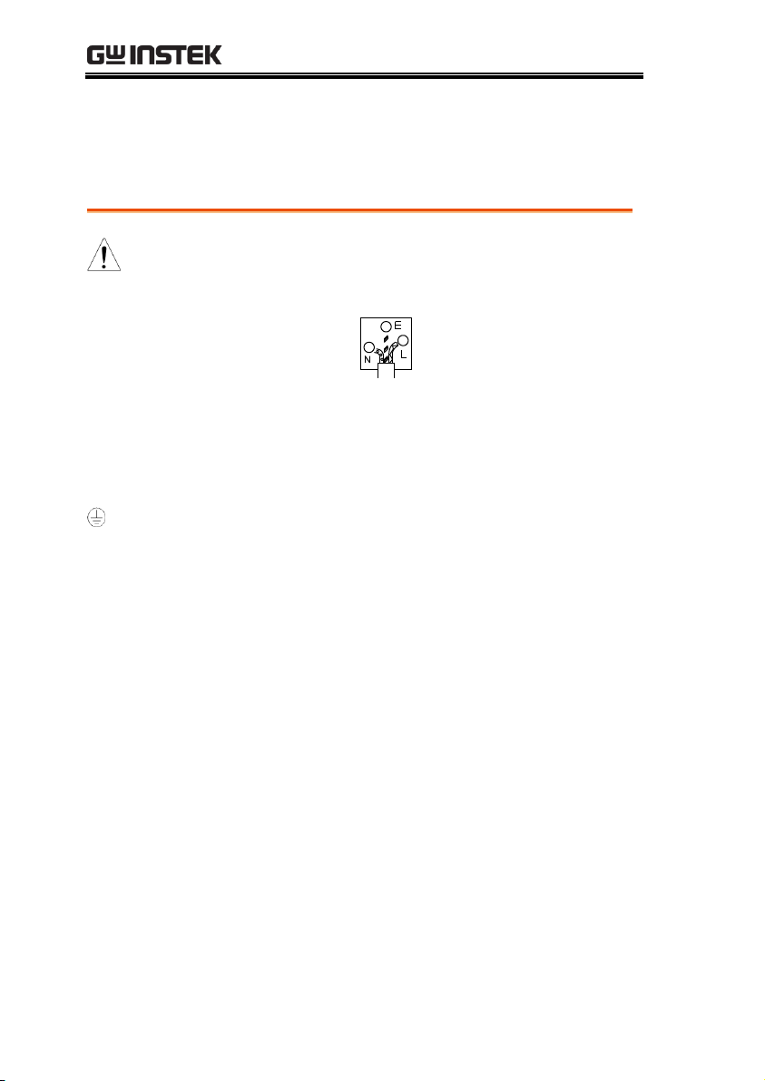
Power cord for the United Kingdom
When using the power supply in the United Kingdom, make sure
the power cord meets the following safety instructions.
NOTE: This lead/appliance must only be wired by competent persons
WARNING: THIS APPLIANCE MUST BE EARTHED
IMPORTANT: The wires in this lead are coloured in accordance with the
following code:
As the colours of the wires in main leads may not correspond with
the coloured marking identified in your plug/appliance, proceed
as follows:
The wire which is coloured Green & Yellow must be connected to
the Earth terminal marked with either the letter E, the earth symbol
or coloured Green/Green & Yellow.
The wire which is coloured Blue must be connected to the terminal
which is marked with the letter N or coloured Blue or Black.
The wire which is coloured Brown must be connected to the
terminal marked with the letter L or P or coloured Brown or Red.
If in doubt, consult the instructions provided with the equipment
or contact the supplier.
This cable/appliance should be protected by a suitably rated and
approved HBC mains fuse: refer to the rating information on the
equipment and/or user instructions for details. As a guide, a cable
of 0.75mm2 should be protected by a 3A or 5A fuse. Larger
conductors would normally require 13A types, depending on the
connection method used.
Any exposed wiring from a cable, plug or connection that is
engaged in a live socket is extremely hazardous. If a cable or plug is
deemed hazardous, turn off the mains power and remove the cable,
any fuses and fuse assemblies. All hazardous wiring must be
immediately destroyed and replaced in accordance to the above
standard.
8

GETTING STARTED
PSU Series Overview................................................ 10
Series lineup ...................................................................................... 10
Main Features ................................................................................... 11
Accessories ........................................................................................ 12
Appearance .............................................................. 15
PSU Series Front Panel ................................................................... 15
PSU Series Display and Operation Panel .................................... 18
Rear Panel .......................................................................................... 20
Theory of Operation ................................................ 23
Operating Area Description ........................................................... 23
CC and CV Mode ............................................................................ 24
Slew Rate ........................................................................................... 26
Bleeder Control ................................................................................ 26
Internal Resistance ........................................................................... 27
Alarms ................................................................................................ 28
Considerations .................................................................................. 30
Grounding ......................................................................................... 33
GETTING STARTED
This chapter describes the power supply in a
nutshell, including its main features and front /
rear panel introduction. After going through the
overview, please read the theory of operation to
become familiar with the operating modes,
protection modes and other safety considerations.
9

PSU Series User Manual
Model name
Voltage Rating1
Current Rating2
Power
PSU 6-200
6V
200A
1200W
PSU 12.5-120
12.5V
120A
1500W
PSU 20-76
20V
76A
1520W
PSU 40-38
40V
38A
1520W
PSU 60-25
60V
25A
1500W
PSU 100-15
100V
15A
1500W
PSU 150-10
150V
10A
1500W
PSU 300-5
300V
5A
1500W
PSU 400-3.8
400V
3.8A
1520W
PSU 600-2.6
600V
2.6A
1560W
1
Minimum voltage guaranteed to 0.2% of rating voltage.
2
Minimum current guaranteed to 0.4% of rating current.
PSU Series Overview
Series lineup
The PSU series consists of 10 models, covering a number of
different current, voltage and power capacities:
10

Main Features
Performance
High power density: 1500W in 1U
Universal input voltage 85~265Vac, continuous
operation.
Output voltage up to 600V, current up to 200A.
Features
Active power factor correction.
Parallel master/slave operation with active
current sharing.
Remote sensing to compensate for voltage drop
in load leads.
19" rack mounted ATE applications.
A built-in Web server.
OVP, OCP and OHP protection.
Preset memory function.
Adjustable voltage and current slew rates.
Bleeder circuit ON/OFF setting.
CV, CC priority start function. (Prevents
overshoot with output ON)
Supports test scripts.
Interface
Built-in RS-232/485, LAN and USB interface.
Analog output programming and monitoring.
Optional interfaces: GPIB, Isolated Voltage (0-
5V/0-10V) and Isolated Current (4-20mA)
programming and monitoring interface.
(Factory options)
GETTING STARTED
11

PSU Series User Manual
Standard
Accessories
Part number
Description
Qty.
Output terminal cover
1
Analog connector plug kit
1
Output terminal M8 bolt set
(6V~60V model)
1
Input terminal cover
1
Power Cord
1
82GW1SAFE0M*1
Safety Guide
1
62SB-8K0HD1*1
1U Handle, ROHS
2 62SB-8K0HP1*1
1U BRACKET (LEFT), RoHS
1
62SB-8K0HP2*1
1U BRACKET (RIGHT), RoHS
1
CD-ROM
User manual, Programming
manual
1 set
82SU-PSU00K*1
Packing list
82GW-00000C*1
* CTC GW/INSTEK JAPAN
USE ,RoHS
1
Factory Installed
Options
Part number
Description
PSU-GPIB
GPIB interface
PSU-ISO-V
Voltage programming isolated
analog interface
PSU-ISO-I
Current programming isolated
analog interface
PSU-001
Front Panel Filter Kit (Operation
Temperature is guaranteed to
40˚C)
Accessories
Before using the PSU power supply unit, check the package
contents to make sure all the standard accessories are included.
12

GETTING STARTED
Optional
Accessories
Part number
Description
PSU-01C
Cable for 2 units of PSU-Series in
parallel mode connection
PSU-01B
Bus Bar for 2 units of PSU-Series in
parallel mode connection
PSU-01A
Joins a vertical stack of 2 PSU units
together. 2U-sized handles x2, joining
plates x2.
PSU-02C
Cable for 3 units of PSU-Series in
parallel mode connection
PSU-02B
Bus Bar for 3 units of PSU-Series in
parallel mode connection
PSU-02A
Joins a vertical stack of 3 PSU units
together. 3U-sized handles x2, joining
plates x2.
PSU-03C
Cable for 4 units of PSU-Series in
parallel mode connection
PSU-03B
Bus Bar for 4 units of PSU-Series in
parallel mode connection
PSU-03A
Joins a vertical stack of 4 PSU units
together. 4U-sized handles x2, joining
plates x2.
PSU-232
RS232 cable with DB9 connector kit.
It Includes RS232 cable with DB9
connector, RS485 used master cable
(gray plug), slave cable (black plug)
and end plug terminal.
PSU-485
RS485 cable with DB9 connector kit.
It Includes RS485 cable with DB9
connector, RS485 used master cable
(gray plug), slave cable(black plug) and
end plug terminal.
GRM-001
Rack-mount slides (General Devices
P/N: C-300-S-116-RH-LH)
13

PSU Series User Manual
GTL-246
USB Cable 2.0-A-B Type, Approx. 1.2M
GPW-001
Power Cord SJT 12AWG/3C, 3m MAX
Length, 105 ºC, RNB5-5*3P UL/CSA
type
GPW-002
Power Cord H05W-F 1.5mm2/3C, 3m
MAX Length, 105 ºC, RNB5-5*3P VDE
type
GPW-003
Power Cord VCTF 3.5mm2/3C, 3m
MAX Length, 105 ºC, RNB5-5*3P PSE
type
Download
Name
Description
psu_cdc.inf
PSU USB driver
Other
Name
Description
Certificate of traceable calibration
14
GETTING STARTED
Lock/Local PROT Function Test Set Output
Unlock ALM_CLR M 1 M 2 M 3
Shift
: Long Push
VSR LAN RMT ERR DLY ALM ISR M 1 M 2 M 3 RUN
C C
A
C V
V
VOLTAGE CURRENT
PSU 40-38
DC Power Supply
0 -40V / 0 - 38A
Voltage Current
2 3 4 5
Display Area
1
116 7 8 9 10 12 13
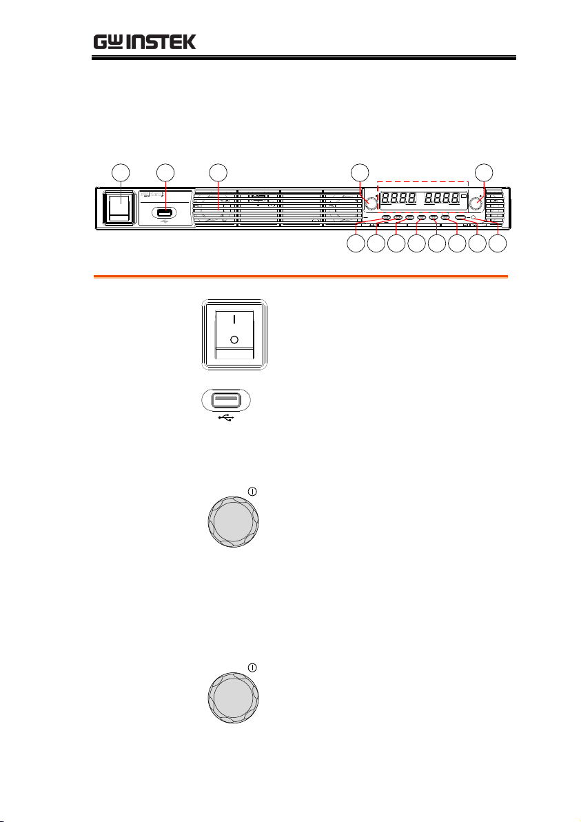
1.
Power Switch
Used to turn the power on/off.
2.
USB A Port
USB A port for data transfer,
loading test scripts etc.
3.
Air Inlet
Air inlet for cooling the inside of
the PSU series.
4.
Voltage Knob
Voltage
Used to set the voltage value or
select a parameter number in the
Function settings.
Display Area
The display area shows setting values, output
values and parameter settings. The function LEDs
below show the current status and mode of the
power supply. See page 18 for details.
5.
Current Knob
Current
Used to set the current value or
change the value of a Function
parameter.
Appearance
PSU Series Front Panel
15
PSU Series User Manual
6.
Lock/Local
Button
Lock/Local
Unlock
Used to lock all front panel
buttons other than the Output
Button or it switches to local
mode.
Unlock
Button
(Long push) Used to unlock the
front panel buttons.
7.
PROT Button
PROT
ALM_CLR
Used to set and display OVP, OCP
and UVL.
ALM_CLR
Button
(Long push) Used to release
protection functions that have
been activated.
8.
Function
Button
Function
M1
Used to configure the various
functions.
M1 Button
(+Shift) Used to recall the M1
setup.
(+Shift and hold) Used to save the
current setup to M1.
9.
Test Button
TEST
M2
Used to run customized scripts for
testing.
M2 Button
(+Shift) Used to recall the M2
setup.
(+Shift and hold) Used to save the
current setup to M2.
10.
Set Button
SET
M3
Used to set and confirm the output
voltage and output current.
M3 Button
(+Shift) Used to recall the M3
setup.
(+Shift and hold) Used to save the
current setup to M3.
16

GETTING STARTED
11.
Shift Button
Shift
Used to enable the functions that
are written in blue characters
below certain buttons.
12.
Output
Button
Output
Used to turn the output on or off.
13.
Output ON
LED
Lights in green when the output is
on.
17
PSU Series User Manual
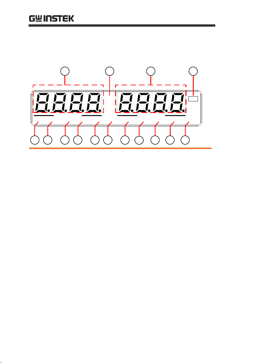
VSR LAN RMT ERR DLY ALM ISR M 1 M 2 M 3 RUN
C C
A
C V
V
VOLTAGE
CURRENT
Display Area
14 1516 17
18 19 20 21 22 23 24
25
26 27 28
14.
Voltage
Meter
Displays the voltage or the parameter number of a
Function parameter.
15.
Current
Meter
Displays the current or the value of a Function
parameter.
16.
CV LED
Lights in green during constant voltage mode.
17.
CC LED
Lights in green during constant current mode.
18.
VSR LED
Lights up when CV Slew Rate Priority is enabled.
19.
LAN LED
Lights up when the LAN interface is connected.
20.
RMT LED
Lights in green during remote control.
21.
ERR LED
Lights in red when an error has occurred.
22.
DLY LED
The Output On/Off Delay indicator LED.
23.
ALM LED
Lights in red when a protection function has been
activated.
PSU Series Display and Operation Panel
18

GETTING STARTED
24.
ISR LED
Lights up when CC Slew Rate Priority is enabled.
25.
M1 LED
Lights in green when the memory value are being
recalled or saved.
26.
M2 LED
Lights in green when the memory value are being
recalled or saved.
27.
M3 LED
Lights in green when the memory value are being
recalled or saved.
28.
RUN LED
Lights up when a Test Script has been activated.
Note
Only the ERR and ALM LED’s are red. All the
others are green.
19

Rear Panel
S LS SLSNC
REMOTE SENSE
ANALOG PROGRAMMING
RS485 / 232
OUT IN
LAN
DC OUTPUT
AC INPUT
L N
100 240V
2000VA MAX.
AC
47 63Hz
234 15678
9 10
87654321
0 -5V / 0 - 10V
ISOLATED PROGRAMMING
87654321
4 -20mA
ISOLATED PROGRAMMING
6-60V models:
PSU 6-200, 12.5-120,
20-76, 40-38, 60-25
100-600V models:
PSU 100-15, 150-10,
300-5, 400-3.8, 600-2.6
S LS SLSNC
REMOTE SENSE
ANALOG PROGRAMMING
OUT IN
RS485 / 232
LAN
L N
AC INPUT
100 240V
2000VA MAX.
AC
47 63Hz
1.
AC Input
L N
AC INPUT
Wire clamp connector.
2.
DC Output
Output terminals for 6V to 60V
models.
Output terminals for 100V to 600V
models.
3.
USB
USB port for controlling the PSU
remotely.
PSU Series User Manual
20
GETTING STARTED
4.
LAN
LAN
RS 485 / 232
Ethernet port for controlling the
PSU remotely.
5.
Remote-IN
LAN
RS 485 / 232
Two different types of cables can
be used for RS232 or RS485-based
remote control.
PSU-232: RS232 cable with DB9
connector kit.
PSU-485: RS485 cable with DB9
connector kit.
6.
Remote-OUT
LAN
RS 485 / 232
RJ-45 connector that is used to
daisy chain power supplies with
the Remote-IN port to form a
communication bus.
PSU-485S: Serial link cable with
RJ-45 shielded connector.
7.
Analog
Control
ANALOG PROGRAMMING
External analog control connector.
8.
Remote
Sense
S LS SLSNC
Compensation of load wire drop.
9.
Option Slot
87654321
0 - 5V / 0 - 10V
ISOLATED PROGRAMMING
Blank sub-plate for standard units.
Isolated Analog connector for
units equipped with Isolated
Current and Voltage
Programming and Monitoring
option.
GPIB connector for units equipped
with IEEE programming option.
21

PSU Series User Manual
10.
Ground
Screw
Connectors for grounding the output (two
positions, shown in red).
L N
AC INPUT
100 240V
2000VA MAX.
AC
47 63Hz
22

GETTING STARTED
Background
The PSU power supplies are regulated DC
power supplies with a high voltage and current
output. These operate in CC or CV mode
within a wide operating range limited only by
the voltage or current output.
The operating area of each power supply is
determined by the rated output power as well
as the voltage and current rating.
Below is a comparison of the operating areas of
each power supply.
PSU Series Operating Area (6-60V models)
Current (A)
Voltage (V)
20
38 76 120
40
120 1801608060 1000 140
0
10
20
30
200
60
200
40
50
60
25
6
12.5
20 40
PSU 6-200
PSU 12.5-120
PSU 20-76
PSU 40-38
PSU 60-25
Theory of Operation
The theory of operation chapter describes the basic principles of
operation, protection modes and important considerations that
must be taken into account before use.
Operating Area Description
23

PSU Series User Manual
PSU Series Operating Area (100-600V models)
Current (A)
Voltage (V)
300
3.8 5 10
400
12 1686 10
0
14
0
100
200
300
15
600
400
500
600
2.6
100
150
PSU 100-15
PSU 150-10
PSU 300-5
PSU 400-3.8
PSU 600-2.6
42
CC and CV mode
Description
When the power supply is operating in
constant current mode (CC) a constant current
will be supplied to the load. When in constant
current mode the voltage output can vary,
whilst the current remains constant. When the
load resistance increases to the point where the
set current limit (I
SET
) can no longer be
sustained the power supply switches to CV
mode. The point where the power supply
switches modes is the crossover point.
When the power supply is operating in CV
mode, a constant voltage will be supplied to
the load, whilst the current will vary as the
load varies. At the point that the load
resistance is too low to maintain a constant
voltage, the power supply will switch to CC
mode and maintain the set current limit.
The conditions that determine whether the
power supply operates in CC or CV mode
depends on the set current (I
SET
), the set voltage
CC and CV Mode
24

GETTING STARTED
(V
SET
), the load resistance (RL) and the critical
resistance (RC). The critical resistance is
determined by V
SET/ISET
. The power supply
will operate in CV mode when the load
resistance is greater than the critical resistance.
This means that the voltage output will be
equal to the V
SET
voltage but the current will be
less than I
SET
. If the load resistance is reduced
to the point that the current output reaches the
I
SET
level, the power supply switches to CC
mode.
Conversely the power supply will operate in
CC mode when the load resistance is less than
the critical resistance. In CC mode the current
output is equal to I
SET
and the voltage output is
less than V
SET
.
RL=R
C
RL<R
C
VSET
ISET
CV
CC
V
I
RL>R
C
Crossover
point
Note
For loads that generate a transient surge voltage,
VSET must be set so that the surge voltage does
not reach the voltage limit.
For loads in which transient peak current flows,
ISET must be set so that the peak value does not
reach the current limit.
25
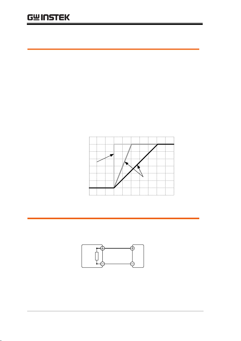
Slew Rate
Theory
The PSU has selectable slew rates for CC and
CV mode. This gives the PSU power supply the
ability to limit the current/voltage draw of the
power supply. Slew rate settings are divided
into High Speed Priority and Slew Rate
Priority. High speed priority mode will use the
fastest slew rate for the instrument. Slew Rate
Priority mode allows for user adjustable slew
rates for CC or CV mode. The rising and falling
slew rate can be set independently.
High Speed
Priority
mode
Slew rate =
Enabled
Background
The PSU DC power supplies employ a bleed
resistor in parallel with the output terminals.
PSU
Load
Bleed
resistor
Bleed resistors are designed to dissipate the
power from the power supply filter capacitors
when power is turned off and the load is
disconnected. Without a bleed resistor, power
may remain charged on the filter capacitors for
PSU Series User Manual
Bleeder Control
26
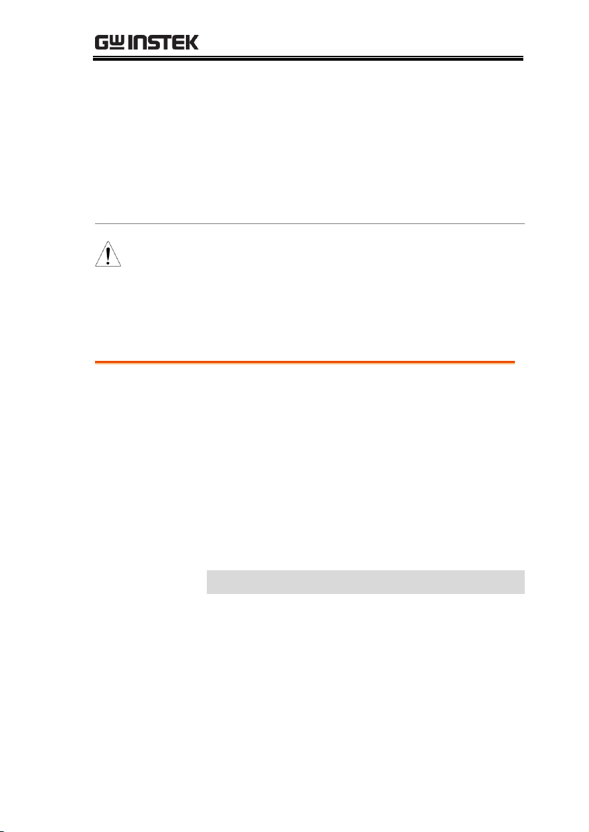
GETTING STARTED
some time and be potentially hazardous.
In addition, bleed resistors also allow for
smoother voltage regulation of the power
supply as the bleed resistor acts as a minimum
voltage load.
The bleed resistance can be turned on or off
using the configuration settings.
Note
By default the bleed resistance is on. For battery
charging applications, be sure to turn the bleed
resistance off as the bleed resistor can discharge
the connected battery when the unit is off.
Background
On the PSU, the internal resistance of the
power supply can be user-defined in software.
(Internal Resistance Setting, see the Normal
Function Settings on page 104.) When the
internal resistance is set it can be seen as a
resistance in series with the positive output
terminal. This allows the power supply to
simulate power sources that have internal
resistances such as lead acid batteries.
By default the internal resistance is 0Ω.
Internal
Resistance Range
Unit Model
Internal Resistance Range
PSU 6-200
0.000 ~ 0.030Ω
PSU 12.5-120
0.000 ~ 0.104Ω
PSU 20-76
0.000 ~ 0.263Ω
PSU 40-38
0.000 ~ 1.053Ω
PSU 60-25
0.000 ~ 2.400Ω
PSU 100-15
0.000 ~ 6.667Ω
PSU 150-10
0.00 ~ 15.00Ω
PSU 300-5
0.00 ~ 60.00Ω
PSU 400-3.8
0.0 ~ 105.3Ω
PSU 600-2.6
0.0 ~ 230.8Ω
Internal Resistance
27

PSU Series User Manual
OVP
Over voltage protection (OVP) prevents a high
voltage from damaging the load. This alarm
can be set by the user.
OCP
Over current protection prevents high current
from damaging the load. This alarm can be set
by the user.
UVL
Under voltage limit. This function sets a
minimum voltage setting level for the output.
It can be set by the user.
OHP
Over temperature protection for slave and
master board. OHP is a hardware protection
function. Only when the unit has cooled can
the over temperature protection alarms be
cleared.
OH1
Master board over temperature protection.
OH2
Slave board over temperature protection.
ALM SENS
Sense alarm. This alarm will detect if the sense
wires have been connected to the wrong
polarity.
HW OVP
Hardware over voltage protection. This is a
hardware OVP that is fixed at approximately
120% of the rated voltage output.
Alarms
The PSU power supplies have a number of protection features.
When one of the protection alarms is tripped, the ALM icon on the
display will be lit and the type of alarm that has been tripped will
be shown on the display. When an alarm has been tripped the
output will be automatically turned off. For details on how to clear
an alarm or to set the protection modes, please see page 53.
28

GETTING STARTED
AC
AC Fail. This alarm function is activated when
a low AC input is detected.
FAN FAIL
Fan failure. This alarm function is activated
when the fan RPMs drop to an abnormally low
level.
Shutdown
Force Shutdown is not activated as a result of
the PSU series detecting an error. It is a
function that is used to turn the output off
through the application of a signal from the
rear-panel analog control connector when an
abnormal condition occurs.
Alarm output
Alarms are output via the analog control
connector. The alarm output is an isolated
open-collector photo coupler output.
29
PSU Series User Manual
Inrush current
When the power supply switch is first turned
on, an inrush current is generated. Ensure there
is enough power available for the power
supply when first turned on, especially if a
number of units are turned on at the same
time.
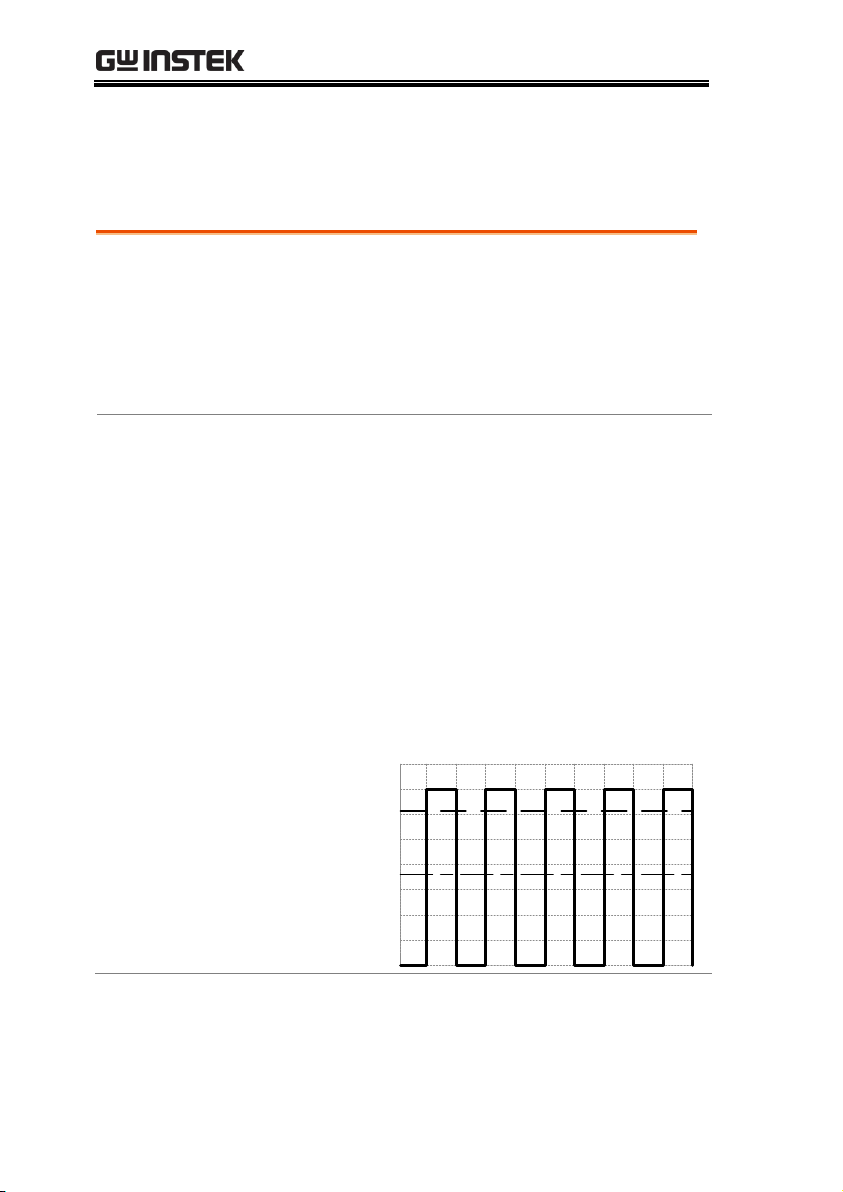
Pulsed or Peaked
loads
When the load has current peaks or is pulsed, it
is possible for the maximum current to exceed
the mean current value. The PSU power supply
ammeter only indicates mean current values,
which means for pulsed current loads, the
actual current can exceed the indicated value.
For pulsed loads, the current limit must be
increased, or a power supply with a greater
capacity must be chosen. As shown below, a
pulsed load may exceed the current limit and
the indicated current on the power supply
ammeter.
Current limit
level
Measured
Ammeter
current
Considerations
The following situations should be taken into consideration when
using the power supply.
30
 Loading...