

Page 1
D.C. Milli-Ohm Meter
GOM-804 & GOM-805
USER MANUAL
GW INSTEK PART NO. 82OM-80500E01
ISO-9001 CERTIFIED MANUFACTURER
5 Commonwealth Ave5 Commonwealth Ave5 Commonwealth Ave5 Commonwealth Ave
Woburn, MA 01801Woburn, MA 01801Woburn, MA 01801Woburn, MA 01801
Phone 781-665-1400Phone 781-665-1400Phone 781-665-1400Phone 781-665-1400
TollTollTollToll Free 1-800-517-8431Free 1-800-517-8431Free 1-800-517-8431Free 1-800-517-8431
Visit us at www.TestEquipmentDepot.com
Page 2

This manual contains proprietary information, which is protected by
copyright. All rights are reserved. No part of this manual may be
photocopied, reproduced or translated to another language without
prior written consent of the Good Will company.
The information in this manual was correct at the time of printing.
However, Good Will continues to improve products and reserves
the right to change specifications, equipment, and maintenance
procedures at any time without notice.
Page 3
Table of Contents
Table of Contents
SAFETY INSTRUCTIONS .................................................... 5
Safety Symbols .................................................... 5
Safety Guidelines ................................................ 6
GETTING STARTED ............................................................ 9
GOM-804/805 Characteristics........................... 10
Key Features ...................................................... 13
Model Lineup .................................................... 14
Front Panel Overview ........................................ 15
TFT-LCD Overview ............................................ 19
Rear Panel Overview ......................................... 21
Set Up ............................................................... 23
MEASUREMENT ............................................................... 27
Resistance Measurement .................................. 29
Compare Function ............................................. 41
Binning Function ............................................... 46
Temperature Measurement ............................... 50
Temperature Compensation .............................. 52
Temperature Conversion ...................................
Measurement Settings ...................................... 60
System Settings ................................................ 69
56
HANDLER/SCAN INTERFACE .......................................... 77
Handler Overview ............................................. 78
Pin Definitions for the Handler Interface .......... 80
Scan Overview ................................................... 82
Configure Interface ........................................... 90
SAVE/RECALL ................................................................... 99
COMMAND OVERVIEW ................................................. 102
Command Syntax ............................................ 102
Command List ................................................. 105
3
Page 4
GOM-804 & GOM-805 User Manual
BINNing Commands ....................................... 108
Calculate Commands ...................................... 113
Memory Commands ........................................ 120
Sense Commands ............................................ 122
Source Commands .......................................... 126
Status Commands ........................................... 127
System Commands.......................................... 128
Temperature Commands ................................. 133
Trigger Commands .......................................... 138
Userdefine Commands .................................... 141
IEEE 488.2 Common Commands ..................... 143
Status system .................................................. 146
FAQ ................................................................................ 147
APPENDIX ...................................................................... 148
Temperature Measurement ............................. 149
Specifications .................................................. 152
Dimensions ..................................................... 155
Declaration of Conformity ............................... 156
INDEX ............................................................................ 157
4
Page 5
SAFETY INSTRUCTIONS
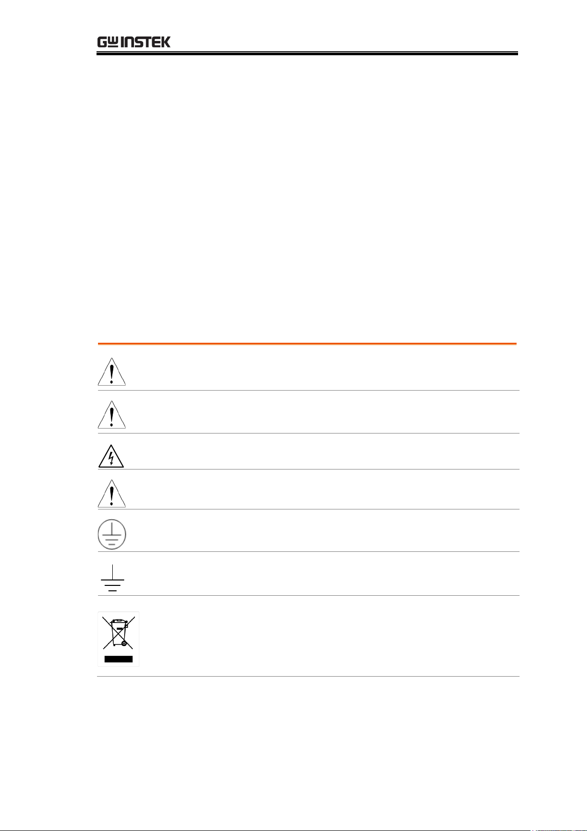
WARNING
Warning: Identifies conditions or practices that could
result in injury or loss of life.
CAUTION
Caution: Identifies conditions or practices that could
result in damage to the instrument or to other properties.
DANGER High Voltage
Attention Refer to the Manual
Protective Conductor Terminal
Earth (ground) Terminal
Do not dispose electronic equipment as unsorted
municipal waste. Please use a separate collection facility
or contact the supplier from which this instrument was
purchased.
SAFETY INSTRUCTIONS
This chapter contains important safety instructions that you must follow
when operating the GOM-804/805 or when keeping it in storage. Read the
following before any operation to insure your safety and to keep the
GOM-804/805 in the best possible condition.
Safety Symbols
These safety symbols may appear in this manual or on the GOM-804/805.
5
Page 6
Safety Guidelines
General Guideline
CAUTION
Do not place any heavy objects on the instrument.
Avoid severe impact or rough handling that leads to
damaging the instrument.
Do not discharge static electricity to the instrument.
Use only mating connectors, not bare wires, for the
terminals.
Do not disassemble the instrument unless you are
qualified as service personnel.
(Note) EN 61010-1:2010 specifies the measurement categories and
their requirements as follows. The GOM-804/805 doesn’t fall
under category II, III or IV.
Measurement category IV is for measurements performed at the
source of low-voltage installation.
Measurement category III is for measurements performed in the
building installation.
Measurement category II is for measurements performed on the
circuits directly connected to the low voltage installation.
Power Supply
WARNING
AC Input voltage: 100 - 240 V AC, 50 - 60Hz, 25VA
The power supply voltage should not fluctuate more
than 10%.
Connect the protective grounding conductor of the AC
power cord to an earth ground, to avoid electrical
shock.
Cleaning the
GOM-804/805
Disconnect the power cord before cleaning.
Use a soft cloth dampened in a solution of mild
detergent and water. Do not spray any liquid into the
instrument.
Do not use chemicals or cleaners containing harsh
material such as benzene, toluene, xylene, and acetone.
Operation
Environment
Location: Indoor, no direct sunlight, dust free, almost
non-conductive pollution (Note below)
Relative Humidity: < 80%
Altitude: < 2000m
Temperature: 0°C to 40°C (operation)
GOM-804 & GOM-805 User Manual
6
Page 7
SAFETY INSTRUCTIONS
(Note) EN 61010-1:2010 specifies the pollution degrees and their
requirements as follows. The GOM-804/805 falls under degree 2.
Pollution refers to “addition of foreign matter, solid, liquid, or
gaseous (ionized gases), that may produce a reduction of dielectric
strength or surface resistivity”.
Pollution degree 1: No pollution or only dry, non-conductive pollution
occurs. The pollution has no influence.
Pollution degree 2: Normally only non-conductive pollution occurs.
Occasionally, however, a temporary conductivity caused by
condensation must be expected.
Pollution degree 3: Conductive pollution occurs, or dry,
non-conductive pollution occurs which becomes conductive due to
condensation which is expected. In such conditions, equipment is
normally protected against exposure to direct sunlight, precipitation,
and full wind pressure, but neither temperature nor humidity is
controlled.
Storage
Environment
Location: Indoor
Temperature: −10°C to 70°C
Disposal
Do not dispose this instrument as unsorted municipal
waste. Please use a separate collection facility or contact
the supplier from which this instrument was purchased.
Please make sure discarded electrical waste is properly
recycled to reduce environmental impact.
7
Page 8
GOM-804 & GOM-805 User Manual
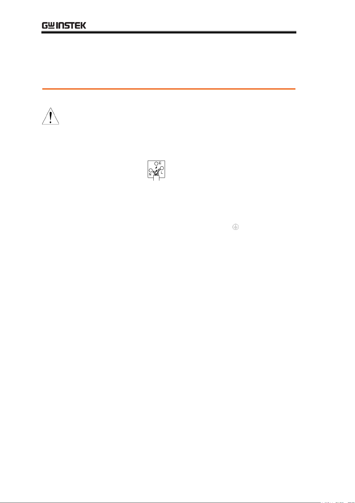
Green/ Yellow:
Earth
Blue:
Neutral
Brown:
Live (Phase)
Power cord for the United Kingdom
When using the instrument in the United Kingdom, make sure the power
cord meets the following safety instructions.
NOTE: This lead / appliance must only be wired by competent persons
WARNING: THIS APPLIANCE MUST BE EARTHED
IMPORTANT: The wires in this lead are coloured in accordance with the
following code:
As the colours of the wires in main leads may not correspond with the
coloured marking identified in your plug/appliance, proceed as follows:
The wire which is coloured Green & Yellow must be connected to the Earth
terminal marked with either the letter E, the earth symbol or coloured
Green/Green & Yellow.
The wire which is coloured Blue must be connected to the terminal which is
marked with the letter N or coloured Blue or Black.
The wire which is coloured Brown must be connected to the terminal marked
with the letter L or P or coloured Brown or Red.
If in doubt, consult the instructions provided with the equipment or contact
the supplier.
This cable/appliance should be protected by a suitably rated and approved
HBC mains fuse: refer to the rating information on the equipment and/or
user instructions for details. As a guide, a cable of 0.75mm2 should be
protected by a 3A or 5A fuse. Larger conductors would normally require 13A
types, depending on the connection method used.
Any exposed wiring from a cable, plug or connection that is engaged in a live
socket is extremely hazardous. If a cable or plug is deemed hazardous, turn
off the mains power and remove the cable, any fuses and fuse assemblies. All
hazardous wiring must be immediately destroyed and replaced in accordance
to the above standard.
8
Page 9
GETTING STARTED
Characteristics
GOM-804/805 Characteristics ................................ 10
Key Features ........................................................... 13
Model Lineup ......................................................... 14
Panel Overview
Front Panel Overview ............................................. 15
TFT-LCD Overview ................................................. 19
Rear Panel Overview ............................................... 21
Setup
Tilt Stand ................................................................ 23
Power Up ................................................................ 24
4 Wire Kelvin Connection ....................................... 25
Zeroing (Relative Function) .................................... 26
GETTING STARTED
This chapter describes the GOM-804/805 in a nutshell, including its main
features as well as its front and rear panels. After going through the panel
overview, follow the Power-up sequence before attempting to use the
instrument.
Please note the information in this manual was correct at the time of printing.
However as GW Instek continues to improve its products, changes can occur
at any time without notice. Please see the GW Instek website for the latest
information and content.
9
Page 10
GOM-804 & GOM-805 User Manual
Easy to Use
Features
Each test function on the GOM-804/805 can be easily
activated by pressing a single front panel key. All the
settings and measurement results are displayed and set on
the TFT-LCD panel at the same time making each
function naturally intuitive to use.
Each primary and secondary measurement result is
displayed prominently on the display along with any
corresponding settings. For sequential measurement
results, such as those from the scan or binning function,
are tabulated in an intuitive and easy-to-read format.
In addition, the meters can recall previously used settings
upon startup, allowing the meter to be ready the next
time it used in a matter of moments. The meters can also
save or recall up to 20 sets of function settings.
Performance
The GOM-804/805 has nine selectable measurement
ranges from 50mΩ to 5MΩ, a constant current source of
1uA to 1A, an accuracy of up to 0.05%, a 1uΩ resolution
and performs measurements using four wire Kelvin
connections for accurate, consistent measurements.
The ability to choose between high accuracy
measurements at 10 samples/sec (full scale at 50000
counts) or high speed measurements at 60 samples/sec
(full scale at 50000 counts), allows the GOM-804/805 the
flexibility to fulfill a number of different measurement
roles.
GOM-804/805 Characteristics
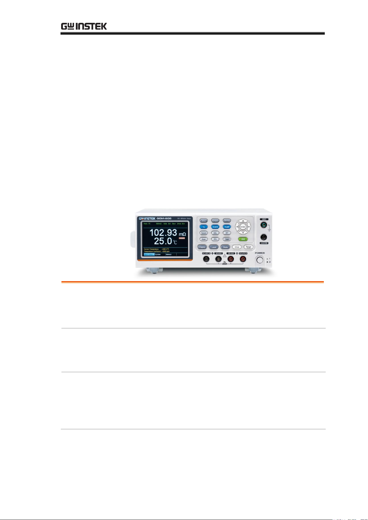
GOM-804 and GOM-805 are modern high precision programmable DC
Milli-ohm meters suitable for low resistance measurements of switches, relays,
connectors, PCB tracks and a variety of other devices. The meters feature a
color TFT-LCD screen with easy-to-read measurement results. With the
easy-to-use features, superior performance and automatic test interfaces, these
meters are dependable instruments for resistance measurements.
10
Page 11
GETTING STARTED
Advanced
Temperature
Measurements
The GOM-804/805 has a number of advanced
temperature functions that can be used with the optional
temperature probe, PT-100.
The temperature compensation function can extrapolate
what the resistance of a DUT will be at a desired
temperature, if the temperature coefficient of the DUT
and the resistance of the DUT at ambient temperature
are known.
The temperature conversion function can be used to
extrapolate what the temperature rise of a DUT will be at
specified resistance if the initial resistance, initial
temperature and the constant for the DUT are known.
Drive Signals
The GOM-805 can select a number of different drive
signals to suit a number of different measurement
scenarios, for example the Pulse setting can be used to
cancel the effects of thermoelectric EMF on the
measurement results.
Dry Circuit
Testing
Dry circuit testing allows the GOM-805 to measure the
contact resistance of switches and connectors according
to the DIN IEC 512 and ASTM B539 standards. The
open circuit voltage will not exceed 20mV in this mode
to prevent the oxidization layer on metal switches and
connector points from breakdown. GOM-805 only.
Automatic
Testing
For automatic testing The GOM-804/805 has a handler
interface designed for automatic testing. The handler
interface outputs the status of PASS, FAIL, HI, LO,
READY and EOT signals and inputs a trigger control
signal. Automatic testing is used with the binning,
compare and scan functions.
For computer control applications, RS-232 and USB are
standard remote interfaces, with GPIB as standard only
for the GOM-805 and GOM-804G.
11
Page 12
GOM-804 & GOM-805 User Manual
Applications
Production testing for contact resistance of switches,
relays, connectors, cables and printed circuit boards
and other low resistance devices.
Component testing of resistors, motors, fuses and
heating elements.
Incoming inspection and quality assurance testing.
Conductivity evaluation for product design.
12
Page 13
Key Features
50,000 counts
Measurement Range: 50mΩ~5MΩ
Accuracy of up to 0.05%
Compare function
Binning function
Manual or Auto-ranging
Continuous or Triggered measurement modes
Temperature measurement, temperature
compensation and temperature conversion
Four-wire Kelvin measurement method
Selectable power-on settings
Diode test
Alarm settings for function-specific PASS/FAIL test
results
Sampling rate: 10 or 60 sampling/sec
Standard interfaces:
USB/RS232/Scan/Handler/GPIB(GOM-805,
GOM-804G)
Save/Recall settings: 20 memory sets
External I/O logic function
GETTING STARTED
13
Page 14
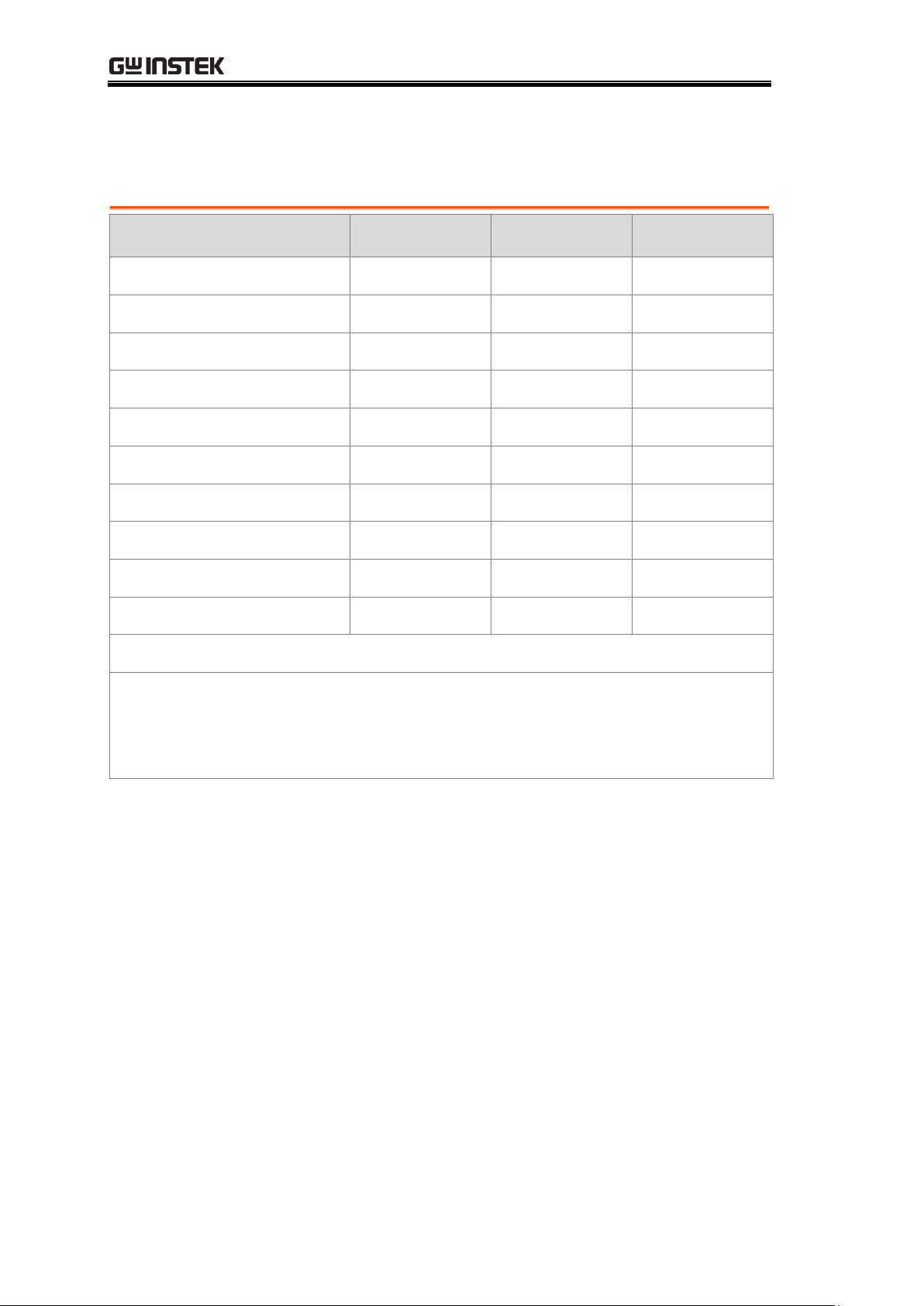
Model Lineup
Feature / Model
GOM-804
GOM-804G*
GOM-805
Ohm Measurement
✔
✔
✔
Compare Function
✔
✔
✔
Diode Measurement
✔
✔
✔
Temp. Compensation
✔
✔
✔
Temp. Conversion
✔
✔
✔
Temp Measurement
✔
✔
✔
Dry Circuit
✘ ✘ ✔
Drive Selection
✘ ✘ ✔
Binning Function
✘ ✘ ✔
GPIB Interface
✘
✔
✔
* The GOM-804G is simply the GOM-804 with the factory-installed
GPIB option. Please note that the GPIB option cannot be
user-installed on the GOM-804. The option must be ordered prior to
purchase.
GOM-804 & GOM-805 User Manual
14
Page 15
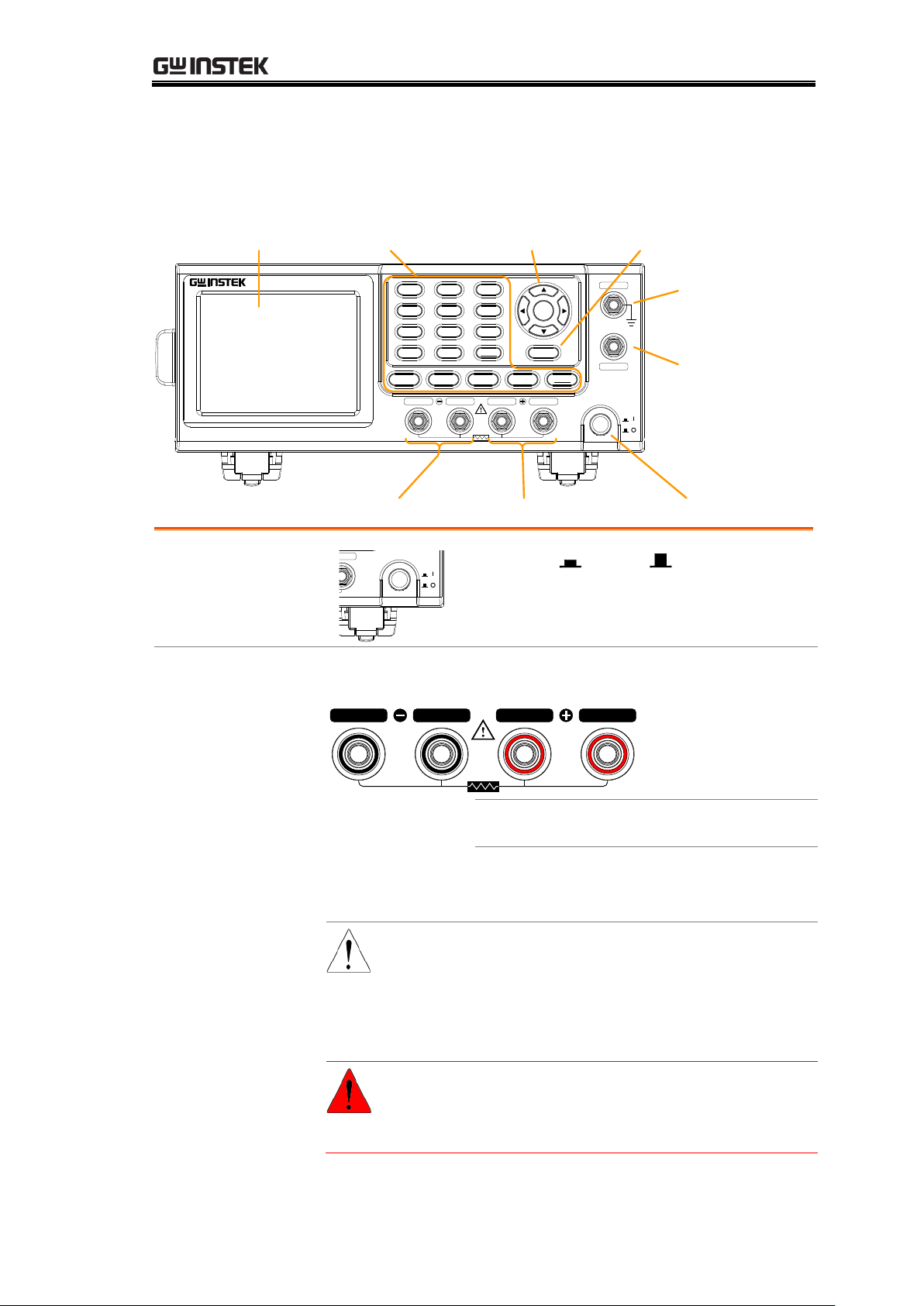
Front Panel Overview
SOURCE SENSE
POWER
SENSE SOURCE
Rx
DC Milliohm Meter
GOM-805
Ohm Compare Binning
TEMP
TCONVTC
Speed
REL RT
Trigger
DryScan
Display
Diode
Drive
ESC
GND
GUARD
Enter
Local
Range
ESC key
GND
terminal
Function keyLCD display
Power key
Arrow keys,
Enter keys
GUARD
terminal
Sense+, Source+Sense-, Source-
Power Switch
POWER
GND
GUARD
Range
Turns On or Off the main
power. For details about the power up
sequence, see page 24.
Measurement Terminals
Source, Sense
Terminals
Rx
SOURCE
SENSE SENSE
SOURCE
Sense + and Sense - terminals.
Current source terminals: Source + and
Source -.
CAUTION
When measuring components
with polarity, connect Source+
to the positive potential and
connect Source- to the negative
potential of the component.
WARNING
Discharge any DUT before
measurement to avoid
damaging the GOM-804/805.
GETTING STARTED
15
Page 16
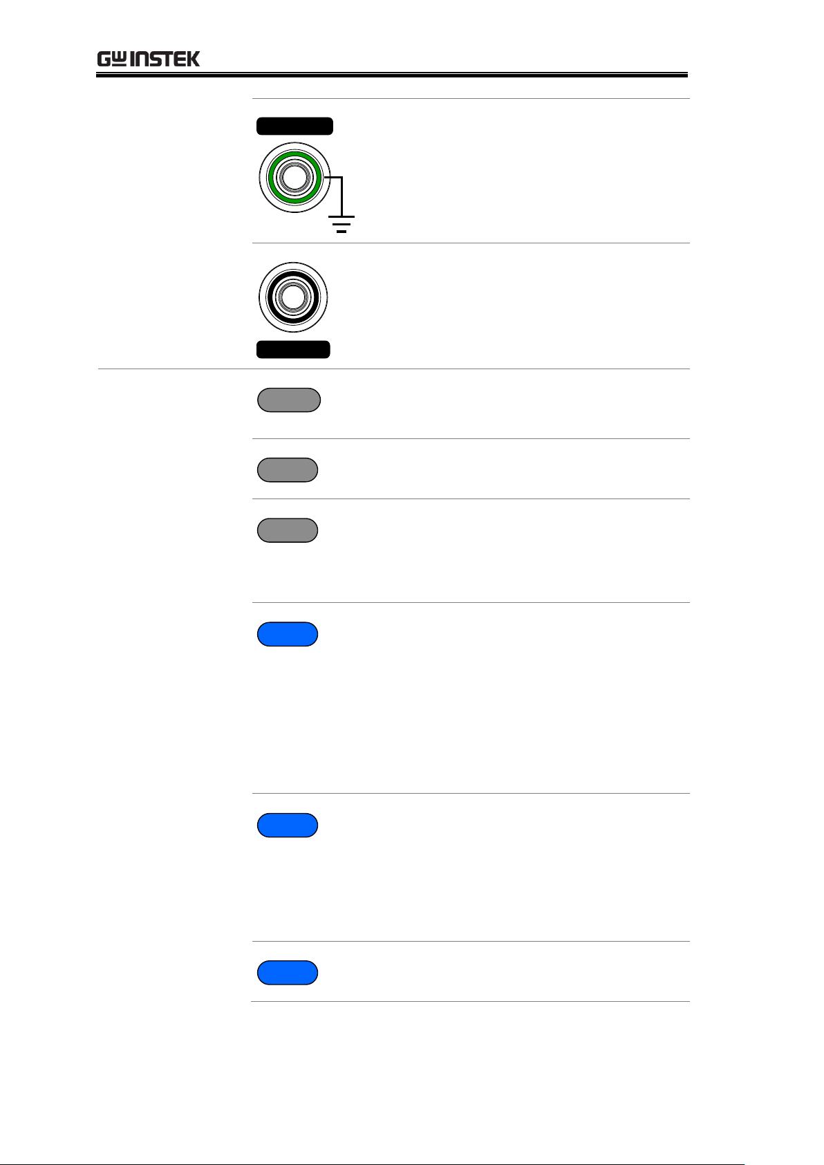
GOM-804 & GOM-805 User Manual
GND Terminal
GND
Connect the GND (ground) terminal to
the earth ground.
GUARD Terminal
GUARD
The GUARD terminal has the same
potential as earth, but cannot be
substituted for it. Connect the GUARD
terminal to the cable shield layer of the
test leads to help reduce noise.
Function Keys
Ohm
The Ohm key activates the resistance
measurement function.
Compare
The Compare key activates the
comparator function.
Binning
The Binning key activates the binning
function to grade the DUTs into eight
bins according to the tolerance settings.
GOM-805 only.
TC
The TC key activates the TC
(temperature compensation) function
which calculates the resistance of a
DUT at a specified temperature given
the resistance of the DUT at the
ambient temperature and the
temperature coefficient of the DUT is
known.
TCONV
The TCONV (Temperature
Conversion) function calculates the
temperature of a DUT given an initial
temperature, initial resistance, measured
resistance and a constant (inferred zero
resistance temperature) for the DUT.
TEMP
The TEMP key activates the
temperature measurement function.
16
Page 17
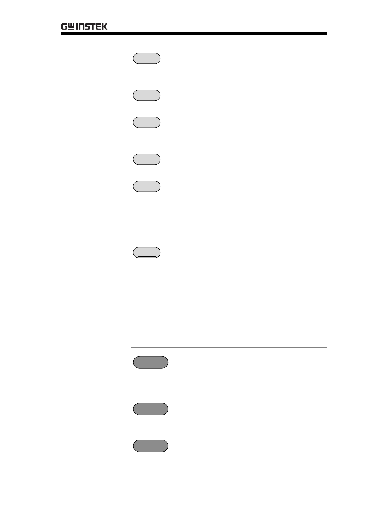
GETTING STARTED
Speed
The Speed key toggles between 10
samples per second and 60 samples per
second (Slow rate and Fast rate).
REL
The REL key is used to perform a zero
adjustment to the test leads or a DUT.
RT
The RT key is used to display the
real-time (not averaged) measured
resistance value.
Scan
The Scan key is used to turn on the
Scan function.
Dry
The Dry key is used to turn on the dry
circuit measurement mode which allows
the GOM-805 to measure the contact
resistance of switches and connectors
according to DIN IEC 512 and ASTM
B539 standards. GOM-805 only.
Trigger
When in the internal trigger mode,
pressing the Trigger key will turn on the
external trigger mode. When in the
external trigger mode, pressing the
Trigger key will perform a manual
trigger.
A long press of the Trigger key when in
external trigger mode will reset the
trigger mode back to the internal trigger
mode.
Display
The Display key toggles between the
standard display mode and the
simplified display mode (sans menus
and display icons).
Local
The LOCAL key will switch the
milliohm meter between local and
remote mode.
Diode
The Diode key is used to turn on the
Diode measurement function.
17
Page 18
GOM-804 & GOM-805 User Manual
Drive
+
Enter
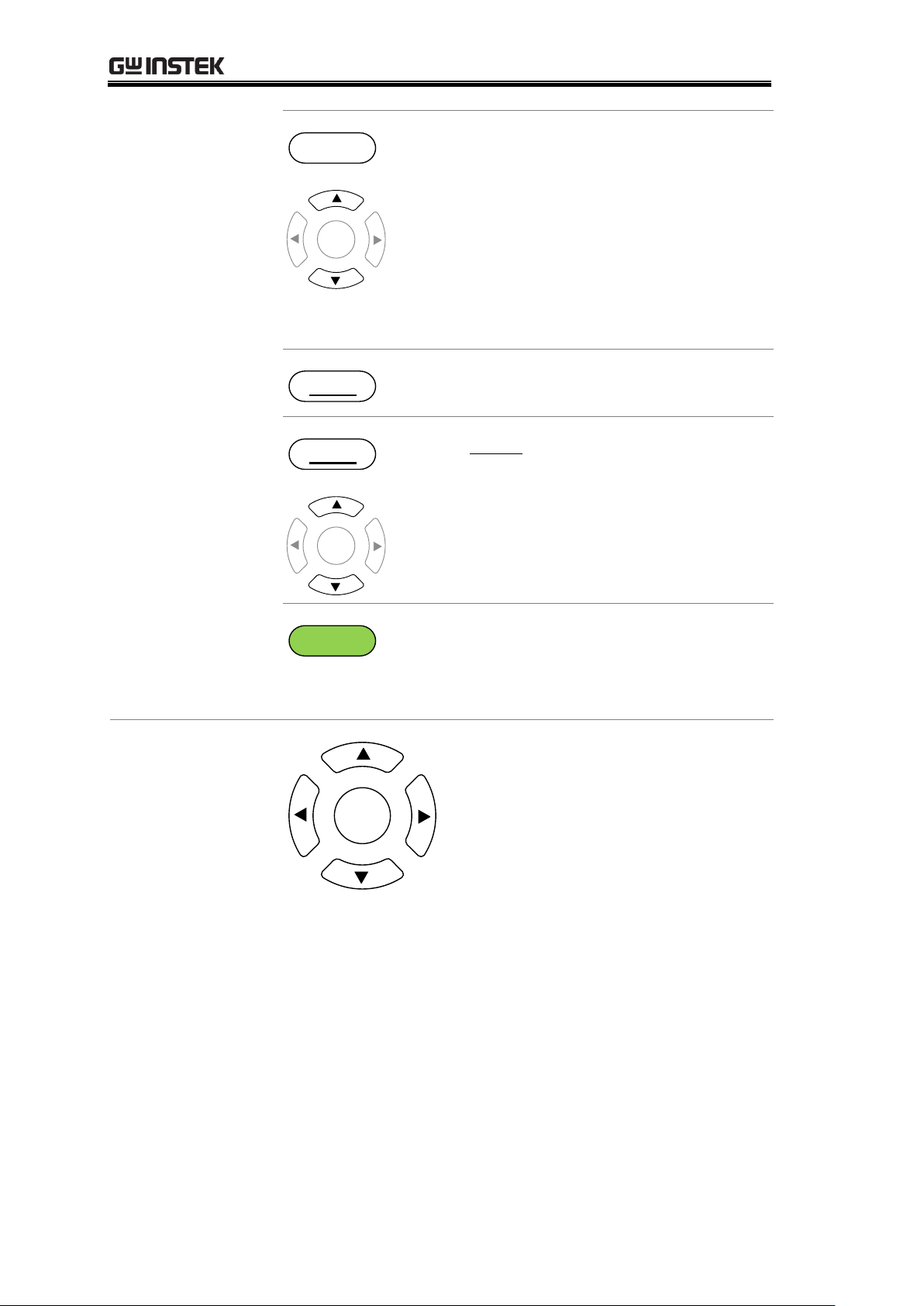
The Drive key in conjunction with the
up/down arrow keys is used to select
the measuring signal: DC+, DC-, Pulse,
PWM, Zero. In particular, the Zero
setting can be used as a +/-10mV DC
voltmeter to measure the EMF of
passive components. See page 33 for
details. GOM-805 only. The drive signal
is fixed to DC+ on the GOM-804.
Range
Long pressing the Range key will
activate the auto ranging mode.
Range
+
Enter
The Range key in conjunction with the
up/down arrow keys is used to select
the resistance measurement range.
When in auto ranging mode, pressing
the Range key will activate the manual
ranging mode.
ESC
The ESC key cancels the current setting
and returns the cursor to its default
location or returns to the previous
menu, depending on the circumstances.
Arrow Keys,
Enter Key
Enter
The arrow keys and Enter key are
used to edit parameters, to navigate
the menu system and to select
parameter ranges.
18
Page 19
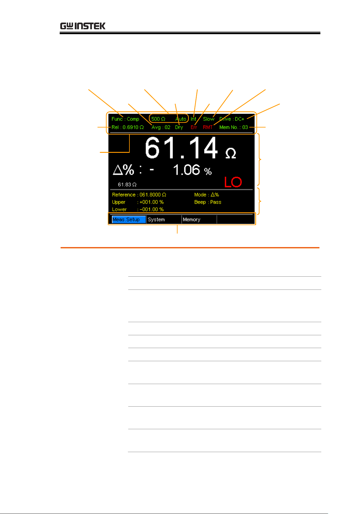
TFT-LCD Overview
Drive signal
RangeFunction mode
Function
mode
settings
Trigger mode
Main
measurement
display
Secondary menus
REL value
Memory
number
Function control
indicators
Average value Dry circuit
Rate
Remote mode
Remote error
Function Control
Indicators
The function control indicators show all the currently
active settings for the selected function mode:
Func
Currently selected function mode
Range
The measurement range. Auto
indicates that auto ranging is
active
Trigger mode
Int/Ext
Rate
Slow/Fast
Drive:
DC+, DC-, Pulse, PWM, Zero
Rel
Shows the relative (nominal)
reference value
Avg
Number of samples used for the
Average function.
Dry
Indicates that the dry circuit
function is active
Err
Indicates a remote command
error
GETTING STARTED
19
Page 20
GOM-804 & GOM-805 User Manual
RMT
Indicates that the unit is in
remote control mode
Mem No.
Indicates which memory setting
has been recalled
Main
Measurement
Display
Shows all measurement results for the selected function
mode.
Function Mode
Settings
Shows any function mode-specific settings.
Secondary
Menus
The secondary menus show global menus (Meas. Setup),
System, Memory) as well as function-specific secondary
menus.
Meas. Setup
Goes to the global Measurement Setup
menu.
System
Goes to the global System menu
Memory
Allows you to save, recall and clear
memory settings.
View
Shows the all results for all the channels
when a scan has finished.
Clear
Clears the measurement results in the
Binning function when the display
mode is set to Count.
20
Page 21
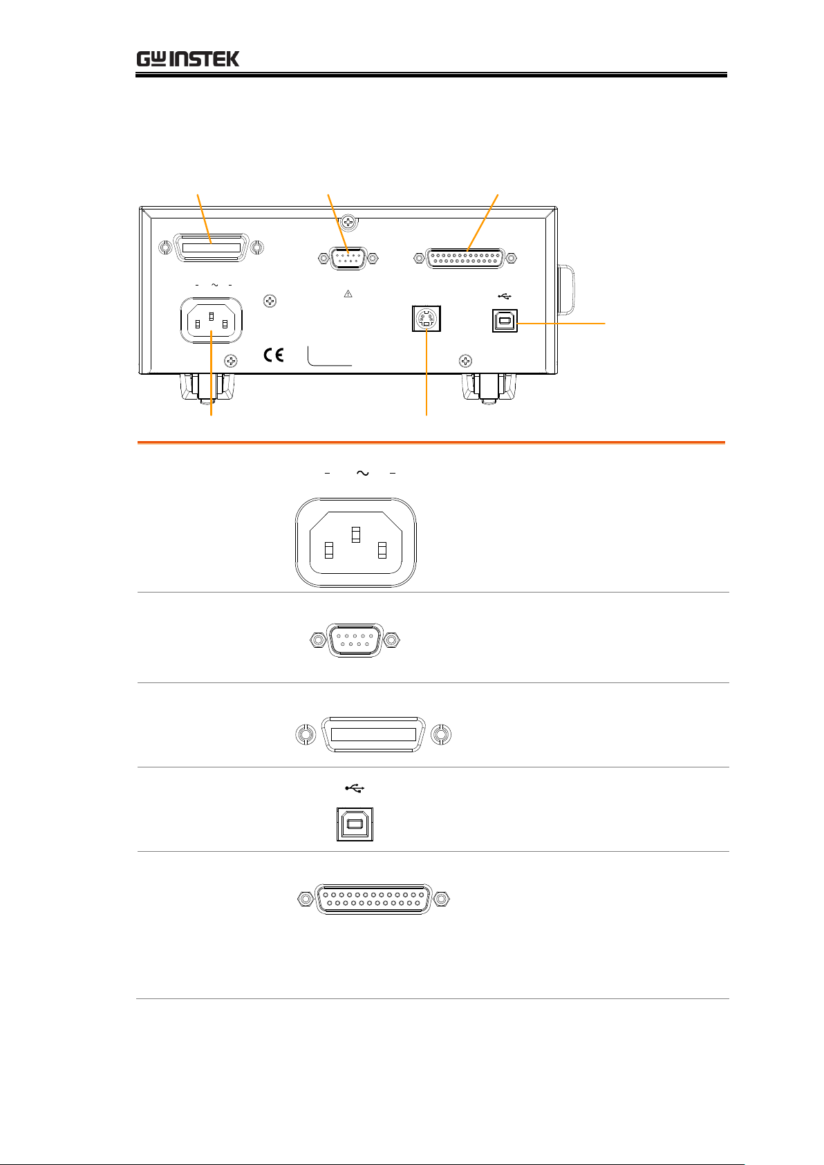
Rear Panel Overview
REMOVE INPUTS BEFORE OPENING.
TO AVOID SHOCK,
WARNING
RS232
SER.NO. LABEL
100 240V , 50 60Hz
25VA MAX
AC
HANDLER / SCAN / EXT I/O
TC SENSOR
GPIB
RS232 portGPIB port Handler/Scan/Ext I/O
USB B
port
Temperature sensor portAC power input
AC Input
100 240V , 50 60Hz
25VA MAX
AC
Accepts the power cord. AC 100 240Vac; 50 - 60Hz.
For the power up sequence, see page
24.
RS-232 Port
RS232
Accepts an RS-232C cable for remote
control; DB-9 male connector.
For remote control details, see page 92.
GPIB Port
GPIB
Accepts a GPIB cable for remote
control. See page 93 for details.
USB Device Port
USB device port for remote control.
See page 90 for details.
Handler / Scan /
EXT I/O Port
HANDLER / SCAN / EXT I/O
The Handler / Scan / EXT I/O
port is used to output
pass/fail/high/low comparison
results. This port is also used for
the user-programmable EXT I/O
pins.
GETTING STARTED
21
Page 22
GOM-804 & GOM-805 User Manual
Temperature
Sensor Port
TC SENSOR
The temperature sensor input is for the
optional PT-100 temperature probe.
22
Page 23
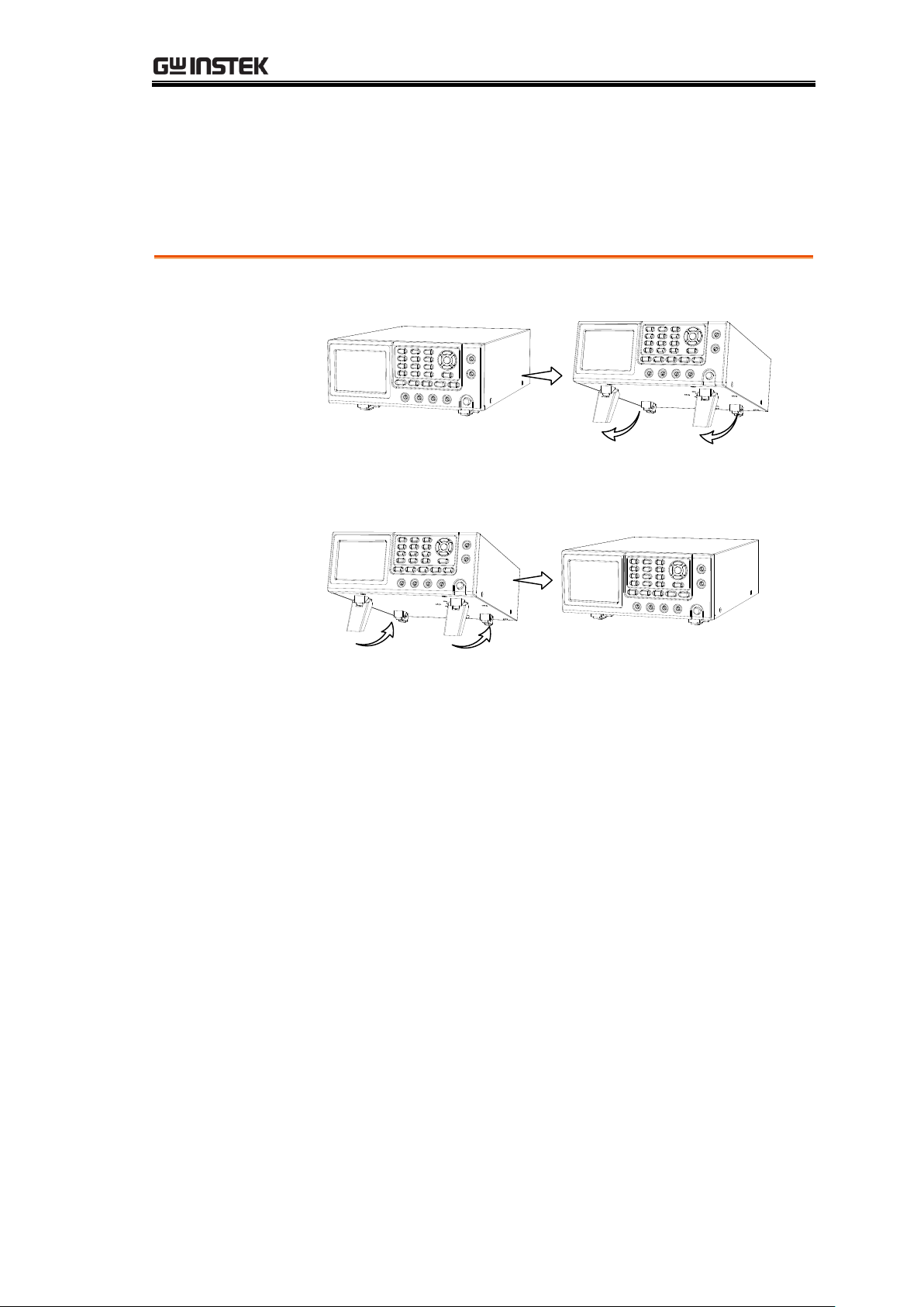
Set Up
Tilt
To tilt, pull the legs forward, as shown below.
Stand Upright
To stand the unit upright, push the legs back under the
casing as shown below.
Tilt Stand
GETTING STARTED
23
Page 24
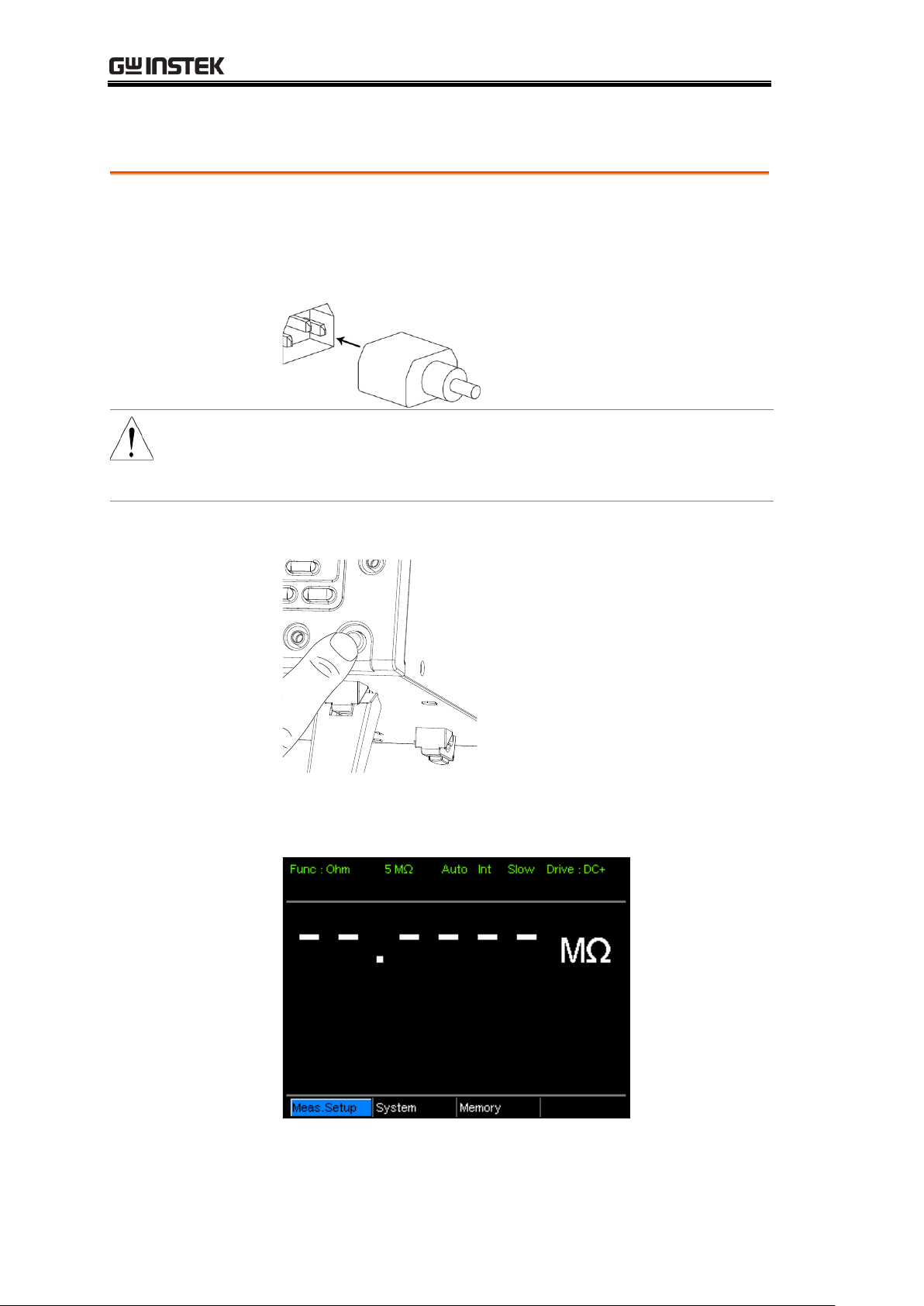
Power Up
1. Connection
Ensure that the input AC power voltage is within the
range of 100~240 V.
Connect the power cord to the AC Voltage input.
CAUTION
Ensure the ground connector of the power cord is
connected to a safety ground. This will affect the
measurement accuracy.
1. Power up
Press the main power switch on the front panel.
The display will light up and show the last setting used
before the last shut down.
Example:
Resistance
measurement
mode
GOM-804 & GOM-805 User Manual
24
Page 25
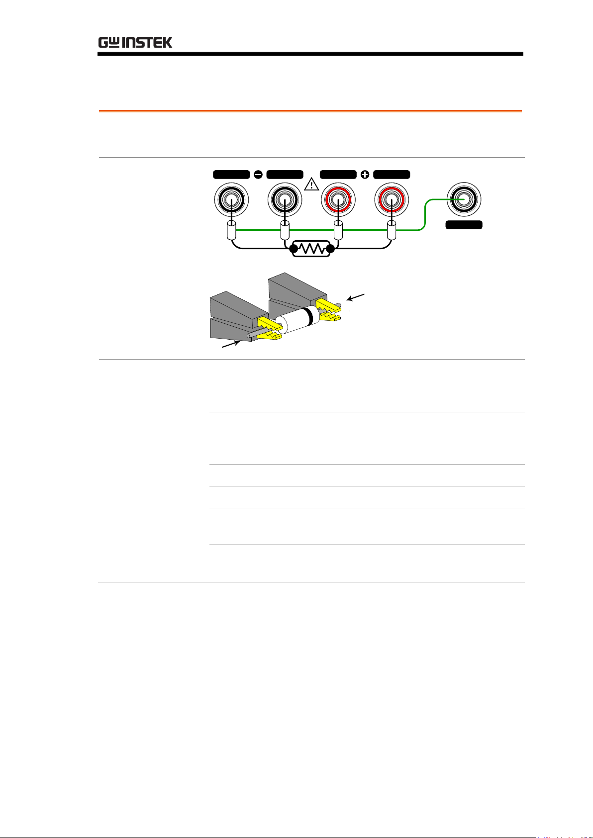
4 Wire Kelvin Connection
Background
The GOM-804/805 uses 4 wire Kelvin connections for
accurate measurements.
Connection
Diagram
GUARD
SOURCE SENSE SENSE
SOURCE
shielding
+
-
Description
Source +
The Source + terminal carries the
measuring current source. It is
connected to the + side of the DUT.
Source -
The Source - terminal accepts the signal
return current and connects to the –
side of the DUT.
Sense +
Monitors the positive (+) potential.
Sense -
Monitors the negative (-) potential.
Guard
Grounds the shielding layer of the test
lead cables to reduce noise.
GND
Provides a reference ground for the
GOM-804/805.
GETTING STARTED
25
Page 26
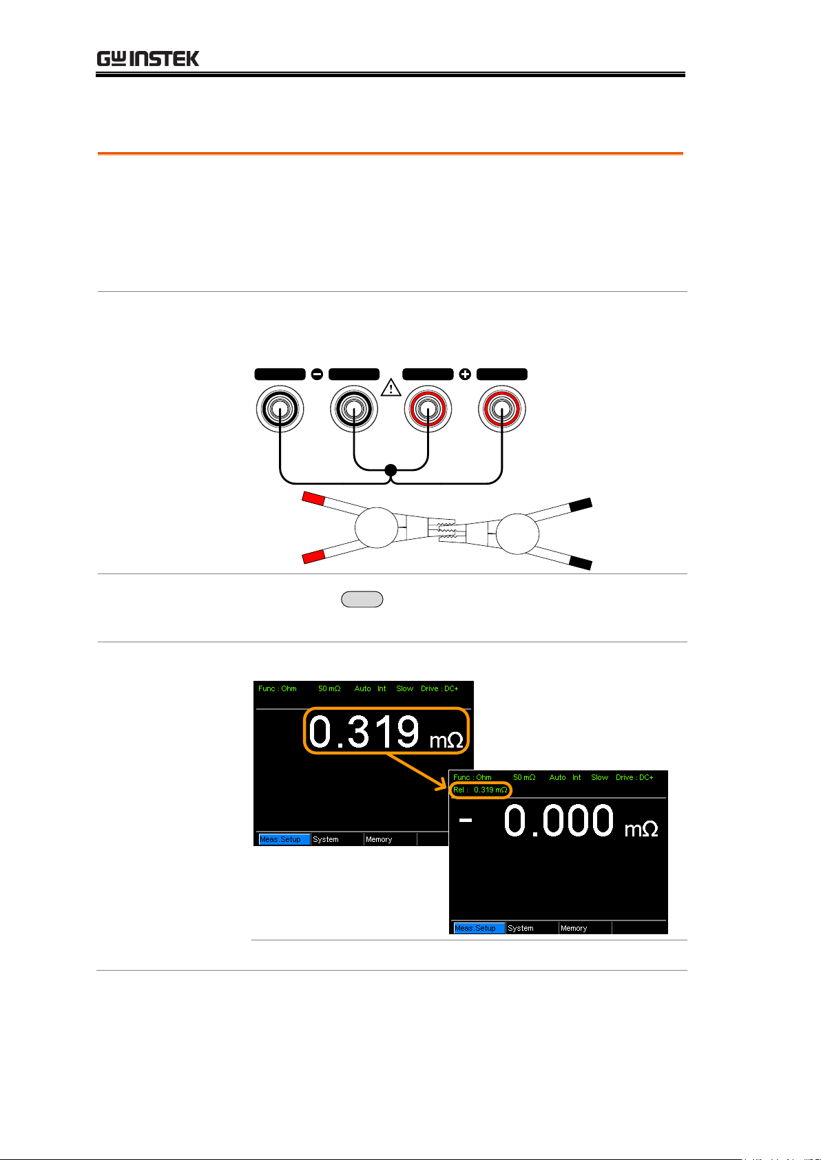
Zeroing (Relative Function)
Background
The Relative function is used to perform a zero
adjustment on the test leads.
After the Relative value is pre-set, each measurement that
is displayed is equal to the actual value minus the relative
preset value.
1. Short the
cables
Short the test cables together as shown in the diagram
below:
SOURCE SENSE SENSE
SOURCE
Source+
/Sense+
Source-
/Sense-
2. Set the
Reference value
Press the
REL
key.
3. Relative mode
display appears
Before REL
After REL
Rel:
Indicates the Relative function is active
GOM-804 & GOM-805 User Manual
26
Page 27
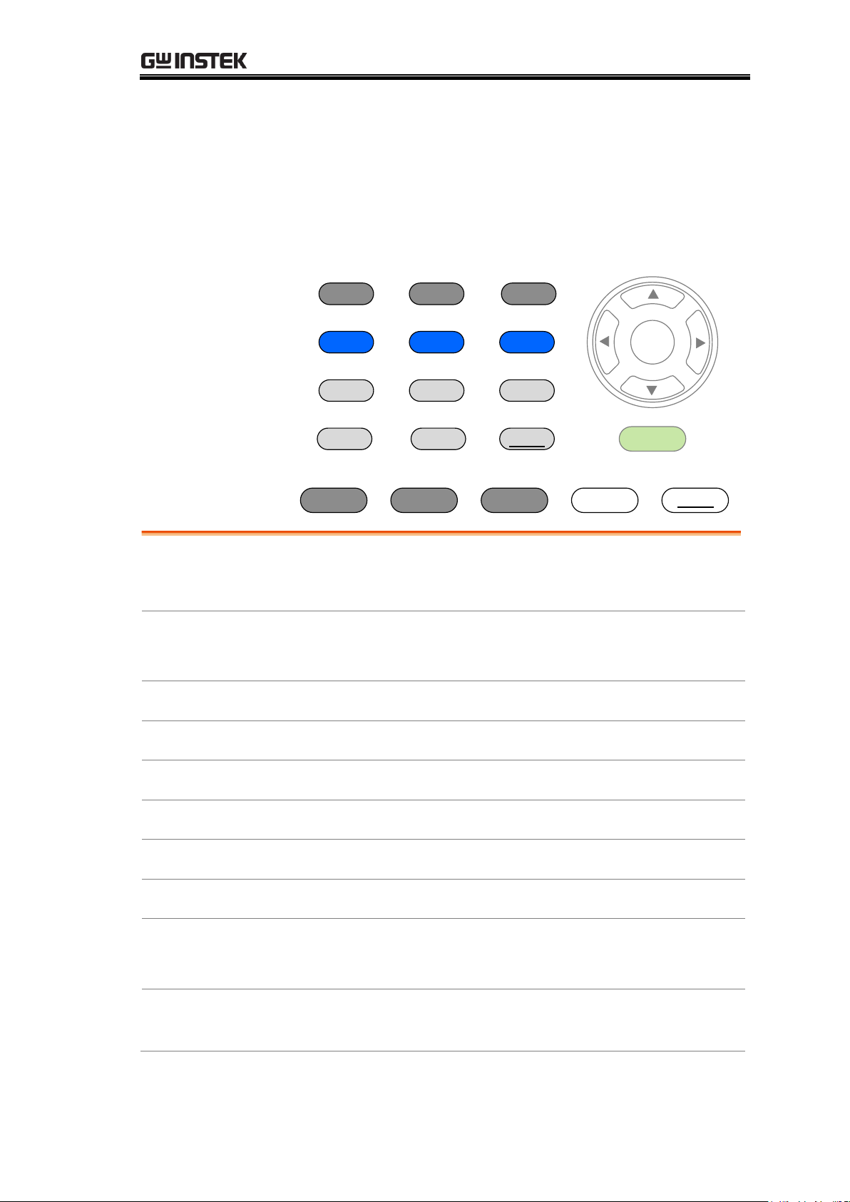
MEASUREMENT
Ohm
TC
Speed
Compare Binning
TCONV TEMP
REL RT
Scan Dry
Display Local Diode Range
ESC
Enter
Trigger
Drive
Resistance
Resistance Measurement ....................................... 29
Select the Resistance Range ................................... 30
Drive Signal
Measuring Signal (Drive) Overview ........................ 31
Select Measuring Signal (Drive) ............................. 33
Rate
Select Measurement Rate ....................................... 34
Display Mode
Display Mode ......................................................... 35
Real-Time
View Real-Time Measurement ................................ 36
Dry-Circuit
Dry-Circuit Measurement ....................................... 37
Trigger
Using the Trigger Function ..................................... 38
Diode
Diode Function ....................................................... 40
Compare
Function
Compare Function .................................................. 41
Binning
Function
Binning Function .................................................... 46
MEASUREMENT
27
Page 28
GOM-804 & GOM-805 User Manual
Temperature
Measurement
Temperature Measurement .................................... 50
Temperature
Compensation
Temperature Compensation ................................... 52
Temperature
Conversion
Temperature Conversion ........................................ 56
Measurement
Settings
Average Function ................................................... 60
Measure Delay ....................................................... 61
Trigger Delay .......................................................... 63
Trigger Edge ........................................................... 64
Temperature Unit ................................................... 65
Ambient Temperature ............................................ 66
Line Frequency ....................................................... 67
PWM Setting .......................................................... 68
System Settings
System Information ............................................... 69
Power On Status Setup .......................................... 70
Interface................................................................. 71
Brightness .............................................................. 72
User Define Pins .................................................... 73
Handler Mode ........................................................ 74
Beep ....................................................................... 76
28
Page 29
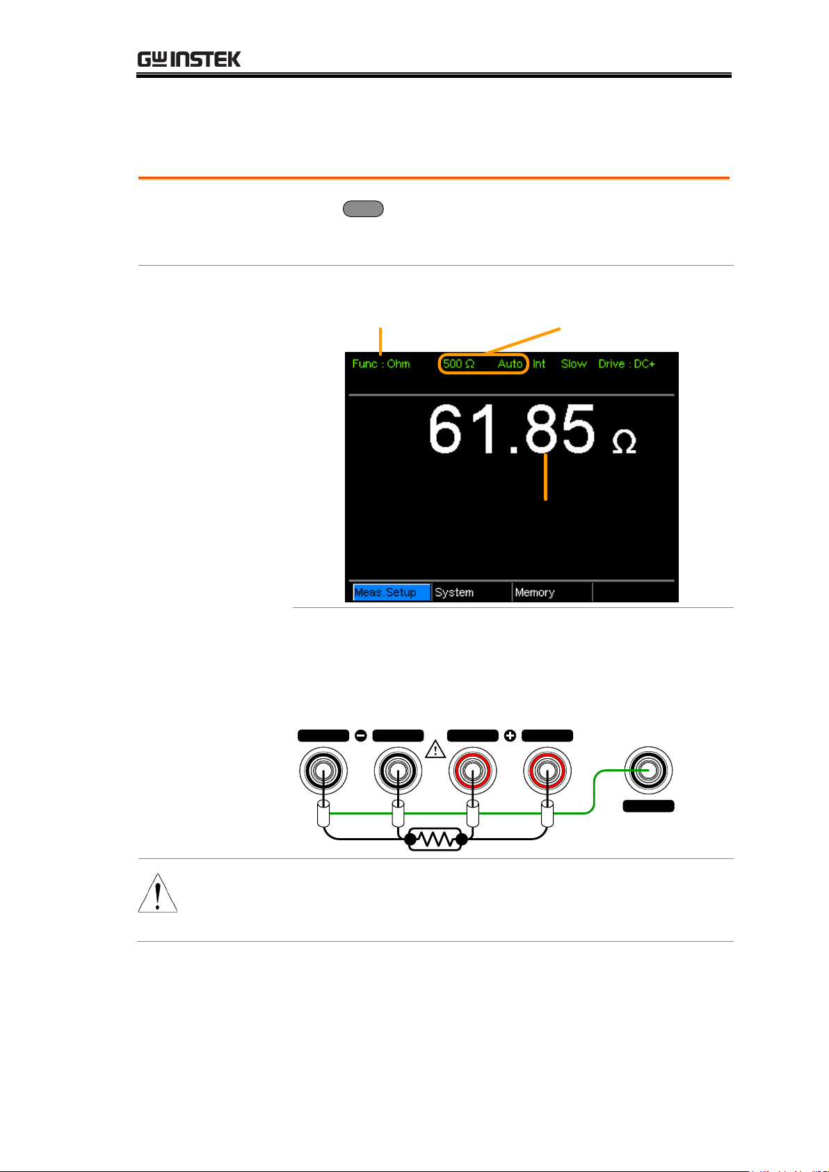
Resistance Measurement
1. Select the
Resistance
function.
Press
Ohm
to access the Resistance measurement
mode.
2. Resistance
mode display
appears.
Ohm measurement
function indicator
Ohm measurement
Resistance range
and mode
3. Connect the
test lead and
measure
4-wire resistance:
Use the SOURCE + and the SOURCE - terminal for
measurement, and the SENSE +, and SENSE - terminal
for sensing.
GUARD
SOURCE SENSE SENSE
SOURCE
shielding
Note
When switching between measurement ranges, please
allow a moment for the circuits to settle before
measuring.
MEASUREMENT
29
Page 30
Select the Resistance Range
Background
The resistance range can be used with normal resistance
measurement as well as the temperature compensation
function.
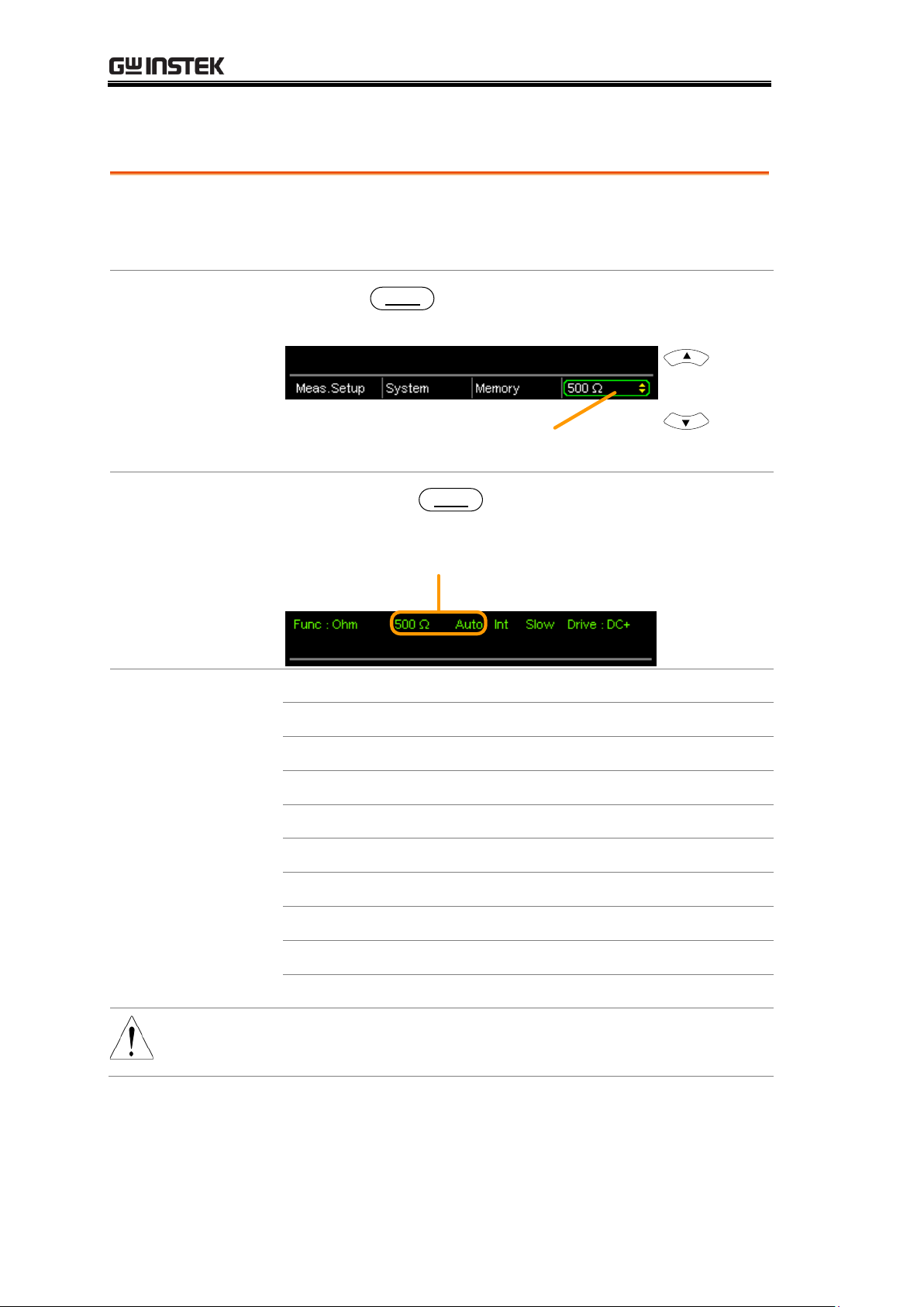
Manual
Press the
Range
key and use the up and down arrow
keys to manually select the resistance range.
Ohm range
Ohm measurement
Range select
indicator
Set range
Auto Range
Long press the
Range
key to turn on automatic
ranging.
Range, Auto range
Selection List
Range
Resolution
50mΩ
1uΩ
500mΩ
10uΩ
5Ω
100uΩ
50Ω
1mΩ
500Ω
10mΩ
5kΩ
100mΩ
50kΩ
1Ω
500kΩ
10Ω
5MΩ
100Ω
Note
For detailed specifications, please see the specifications
on page 152.
GOM-804 & GOM-805 User Manual
30
Page 31
Measuring Signal (Drive) Overview
Background
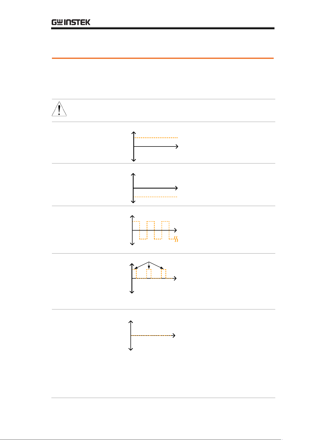
Resistance measurement has 5 different measuring signals
that can be applied to obtain a resistance measurement:
DC+, DC-, Pulse, PWM, Zero.
These 5 signals are described in below.
Note
The drive function is only applicable to the GOM-805.
The drive signal for the GOM-804 is fixed to DC+.
DC+
~ +6.5V
Open circuit
voltage
0V
V
t
Default drive
signal.
DC-
~ -6.5V
Open circuit
voltage
0V
V
t
Negative drive
signal.
Pulse
~-6.5V
0V
V
t
~+6.5V
50ms
50ms
This mode can be used to
eliminate the thermoelectric
EMF formed on the contact
between a test lead and a
DUT.
PWM
0V
V
t
~+6.5V
ON duty
This mode can be used to
avoid heating up the DUT
and thus avoid having the
measurement accuracy
compromised on
temperature-sensitive DUTs.
Zero
0V
V
t
In this mode, GOM-805
outputs no measuring signal
on the Source loop; therefore,
the Sense loop can be used as
a voltage meter which can
measure up to +/-10mV for
thermoelectric EMF
measurement. This function
is useful for measuring the
Vemf of thermocouple wires.
MEASUREMENT
31
Page 32
GOM-804 & GOM-805 User Manual
A note about Thermoelectric EMF
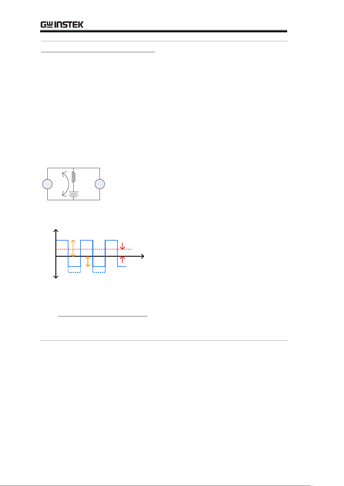
When making low resistance measurements, thermoelectric electromotive
force (Vemf) can affect measurement accuracy. Vemf is created at the junction
of two dissimilar metals, such as the contact point of a test lead and the pin
of a DUT. Vemf adds a small but measurable voltage to the measurement.
There are primarily two different methods to compensate for Vemf in low
resistance measurements: Offset Compensation and Vemf Cancelling. The
GOM-805 uses Vemf Cancelling with the pulse drive signal setting (see page
33).
The Pulse drive mode supplies a positive and a negative measurement current
source.
V
I
R
Vemf
This produces a positive and negative measurement voltage across the DUT,
which also includes the Vemf (V1+Vemf & V2+Vemf).
0V
t
Vemf
V1
V2
To cancel the Vemf, V2 is deducted from V1 and divided by 2 to get the
average measurement, as shown in the formula below:
2
)2()1( VemfVVemfV
Vx
Where Vx = measured voltage sans Vemf.
32
Page 33
Select Measuring Signal (Drive)
Background
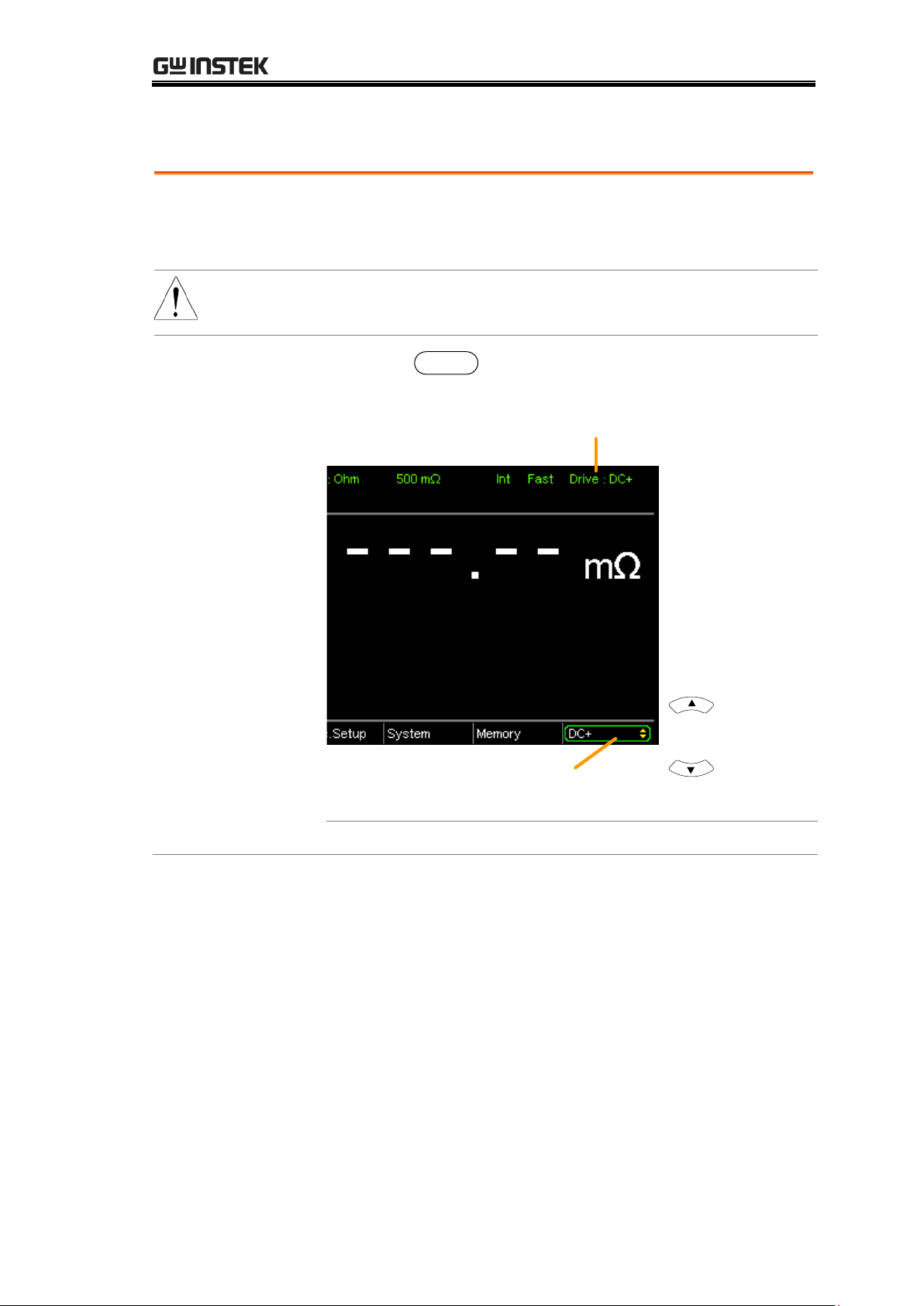
Resistance measurement has 5 different measuring signals
that can be applied to obtain a resistance measurement:
DC+, DC-, Pulse, PWM, Zero.
Note
The drive function is only applicable to the GOM-805.
The drive signal for the GOM-804 is fixed to DC+.
1. Select Drive
Press the
Drive
key and use the up and down arrow
keys to select a drive signal.
Drive mode
Drive selection
indicator
Set drive signal
Drive Range
DC+, DC-, Pulse, PWM, Zero
MEASUREMENT
33
Page 34
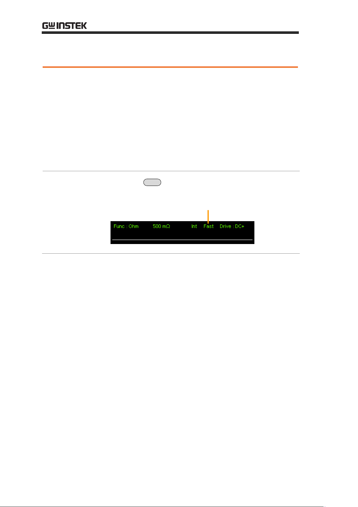
Select Measurement Rate
Background
The resistance measurement speed has 2 ranges: slow and
fast. Slow speed is the most accurate with 10
measurements/second. Fast speed has 60
measurements/second. Both have the same measurement
resolution.
The rate selection function is not applicable in Diode
measurement mode. When the PWM drive signal is used
or when the Scan function is activated, the only available
rate setting is fast.
1. Select Rate
Press the
Speed
key to toggle between the Slow and Fast
rates.
Measurement rate
GOM-804 & GOM-805 User Manual
34
Page 35
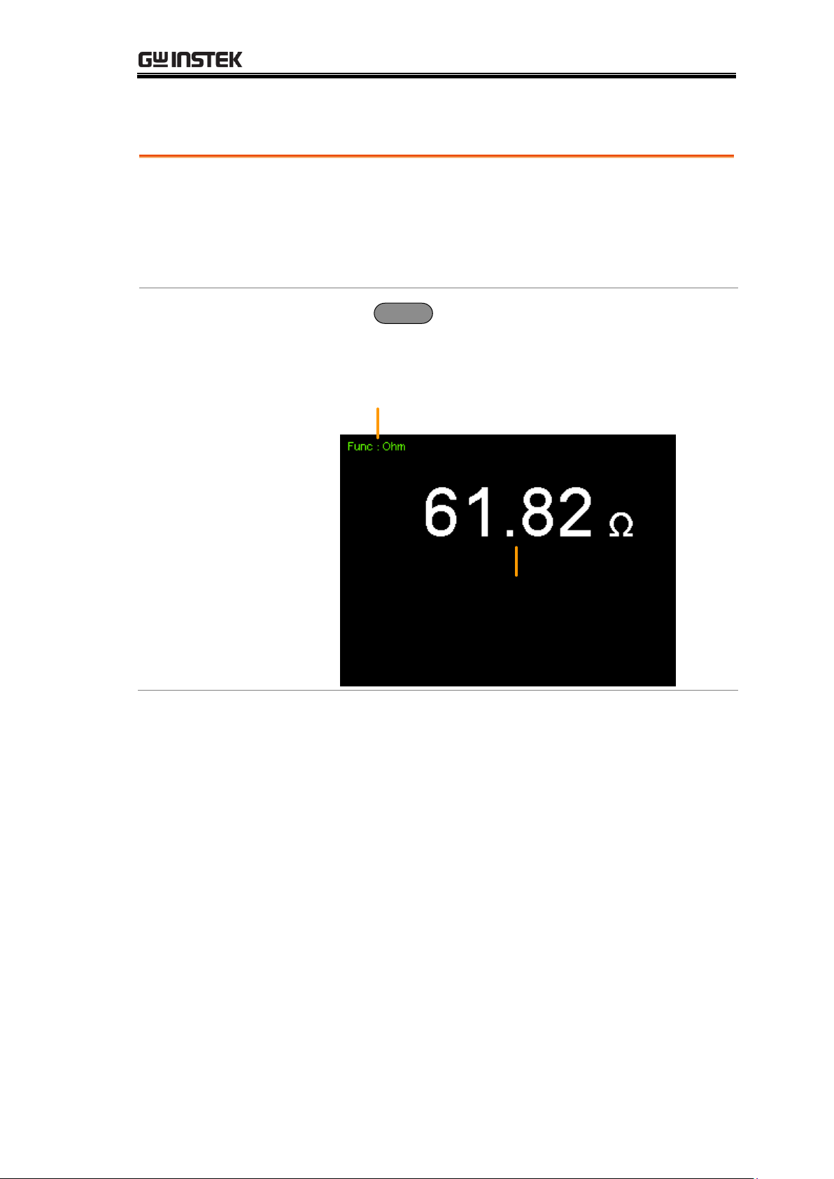
Display Mode
Background
The Display key can be used to toggle between the
normal and the simplified display mode. The simplified
display mode clears all text, menus and function
indicators from the screen except for the measurement
and measurement mode indicators.
1. Toggle Display
mode
Press the
Display
key to toggle the display between
normal and simplified. The display will change
accordingly.
Simplified
Display Mode
Example
Measurement
Measurement mode
MEASUREMENT
35
Page 36
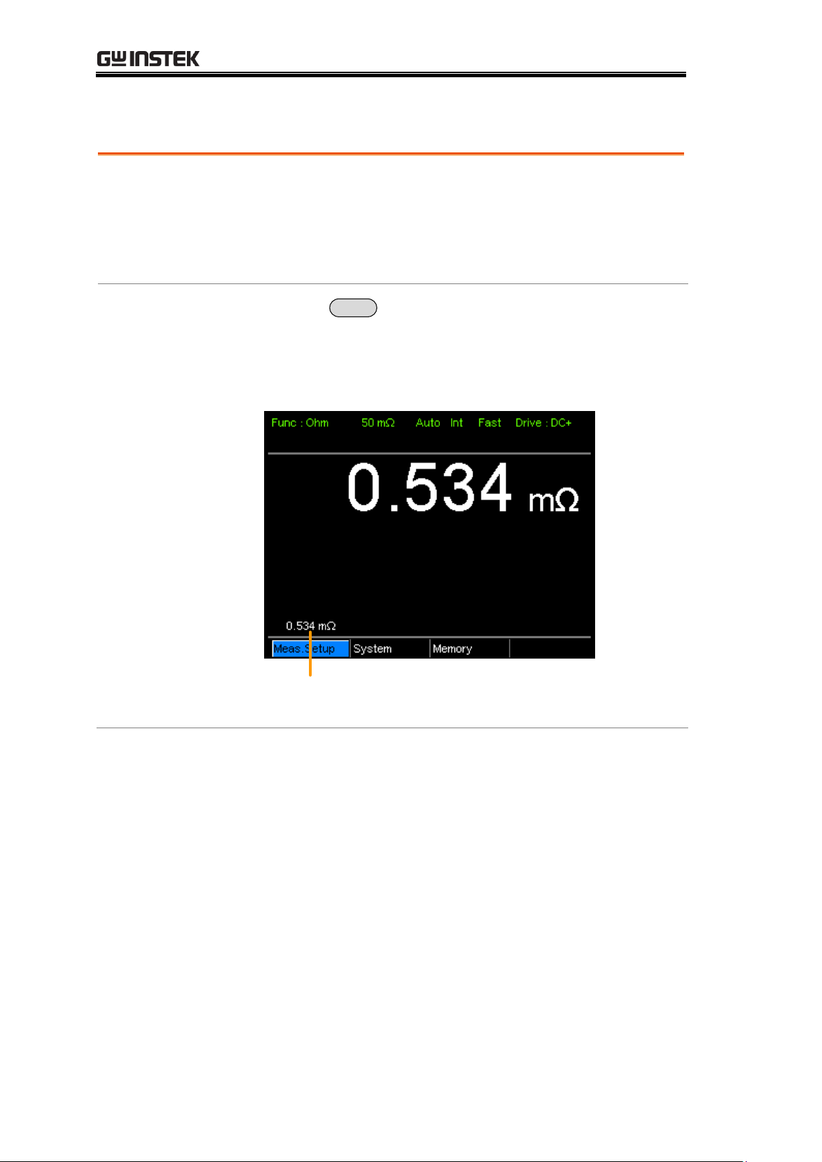
View Real-Time Measurement
Background
When measurements are smoothed using the averaging
function, the RT key can be used to view the real-time
results in addition to the averaged results.
See page 60 for Average configuration.
1. Toggle
Real-Time
display
Press the
RT
key to toggle the real-time display on
or off.
The real-time measurement will appear in the bottom
left-hand corner.
Real-time
measurement
GOM-804 & GOM-805 User Manual
36
Page 37
Dry-Circuit Measurement
Background
The Dry Circuit measurement function is used where the
maximum open-circuit voltage must be kept to a
minimum for applications such as measuring the contact
resistance of switches, relays and connectors. The
GOM-805 provides a maximum of up to 20mV in this
mode.
Note
Dry circuit testing is for switch and connector contact
resistance. Switch and connector contact resistance
measurement is in accordance with DIN IEC 512 and
ASTM B539 which requires that the open circuit voltage
of the measuring device should not exceed 20mV DC.
Voltage at such low levels avoids the breakdown of any
oxides that may be present on the contacts. In this mode
the open circuit measuring voltage is limited <20mV,
while modes like DC+ or pulse mode can have an open
circuit measuring voltage as high as 6.5V.
Dry Limitations
When the Dry Circuit measurement function is turned
on, the measurement range is reduced. See the
specifications for more details.
Range
Dry Mode
Rate
50mΩ
✘
500mΩ
✔
Slow/Fast
5Ω
✔
Slow/Fast
50Ω
✔
Slow/Fast
500Ω
✘
5kΩ
✘
50kΩ
✘
500kΩ
✘
5MΩ
✘
MEASUREMENT
37
Page 38
GOM-804 & GOM-805 User Manual
1. Toggle Dry
mode on or off
Press the
Dry
key to toggle the dry circuit
measurement mode on or off.
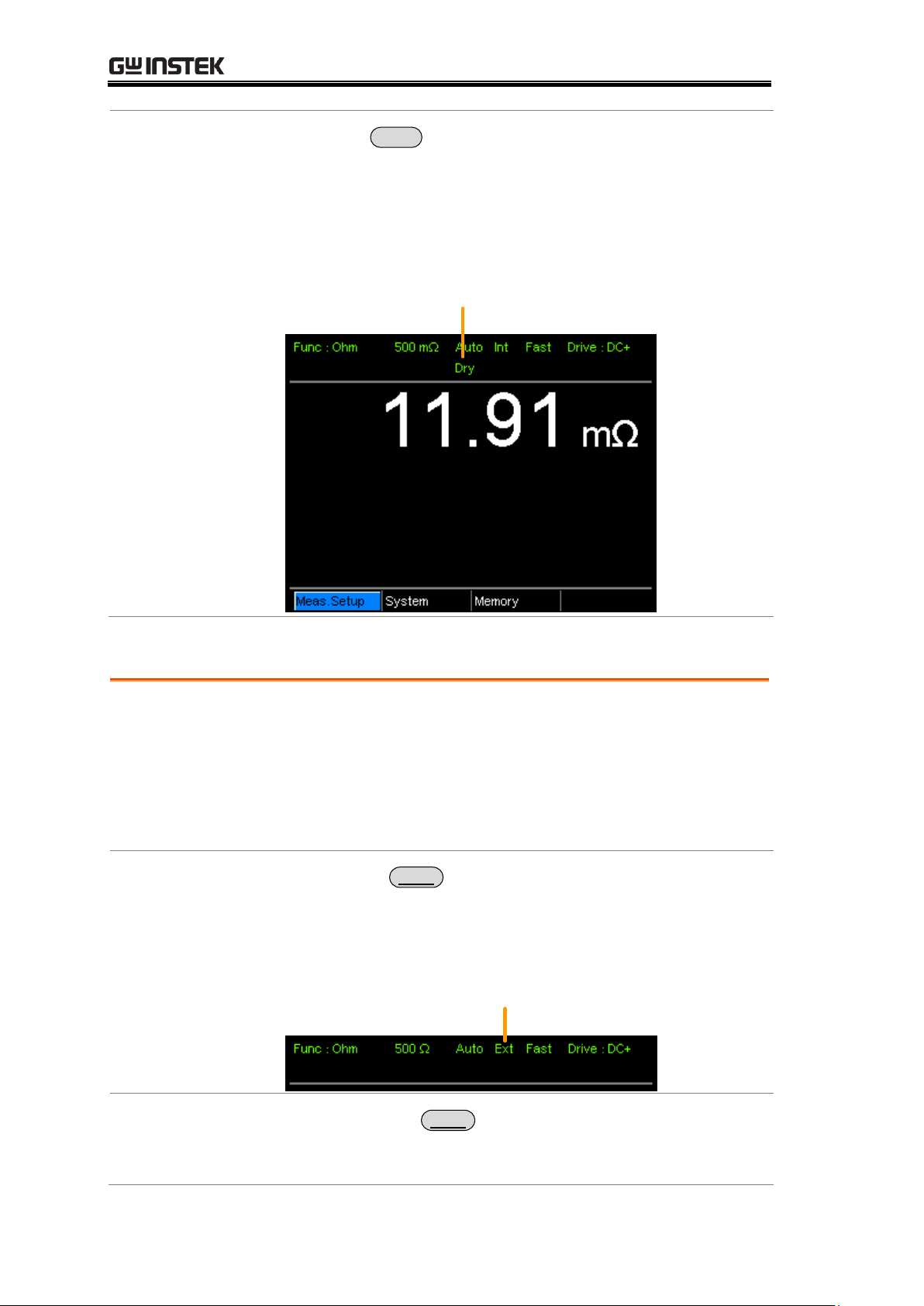
The DRY function indicator will appear in the middle of
the display when active.
Dry Circuit measurement
mode indicator
Background
The GOM-804/805 can use internal or manual triggering
for the Resistance, Temperature, Temperature
Compensation, Temperature Conversion, Binning,
Handler and Scan modes.
By default the GOM-804/805 is set to internal triggering
mode.
1. Select Manual
Trigger
Short press
Trigger
to switch to manual triggering mode.
The Ext indicator will be shown on the display
when the manual trigger is active.
Trigger source
2. Manually
Triggering
Measurements
Short press the
Trigger
key each time you want to start a
single measurement (when in the manual mode).
Using the Trigger Function
38
Page 39
MEASUREMENT
3. Internal
Triggering
Long press
Trigger
to return the triggering mode back to
internal mode.
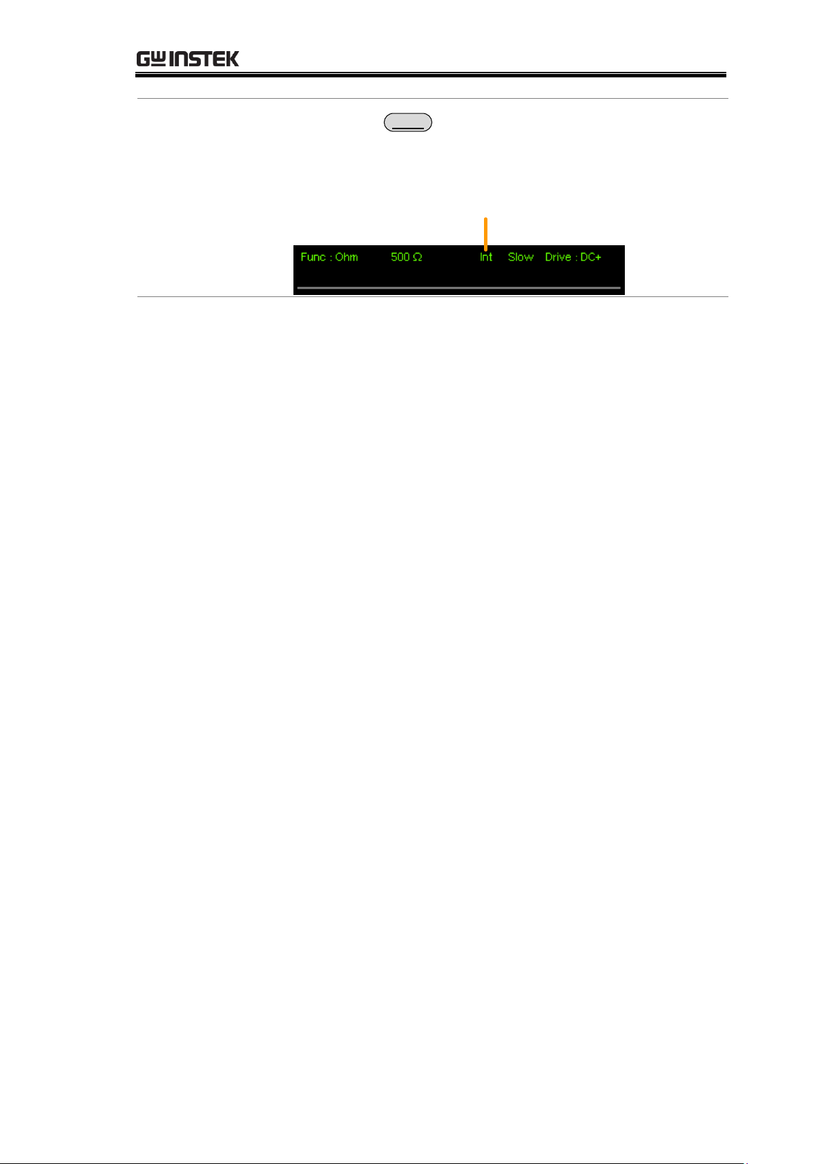
The Int indicator will be shown on the display.
Internal trigger source
39
Page 40
Diode Function
Background
The Diode function can be used to measure the forward
bias voltage of a diode under test.
1. Select the
Diode function.
Press
Diode
to access the Diode measurement mode.
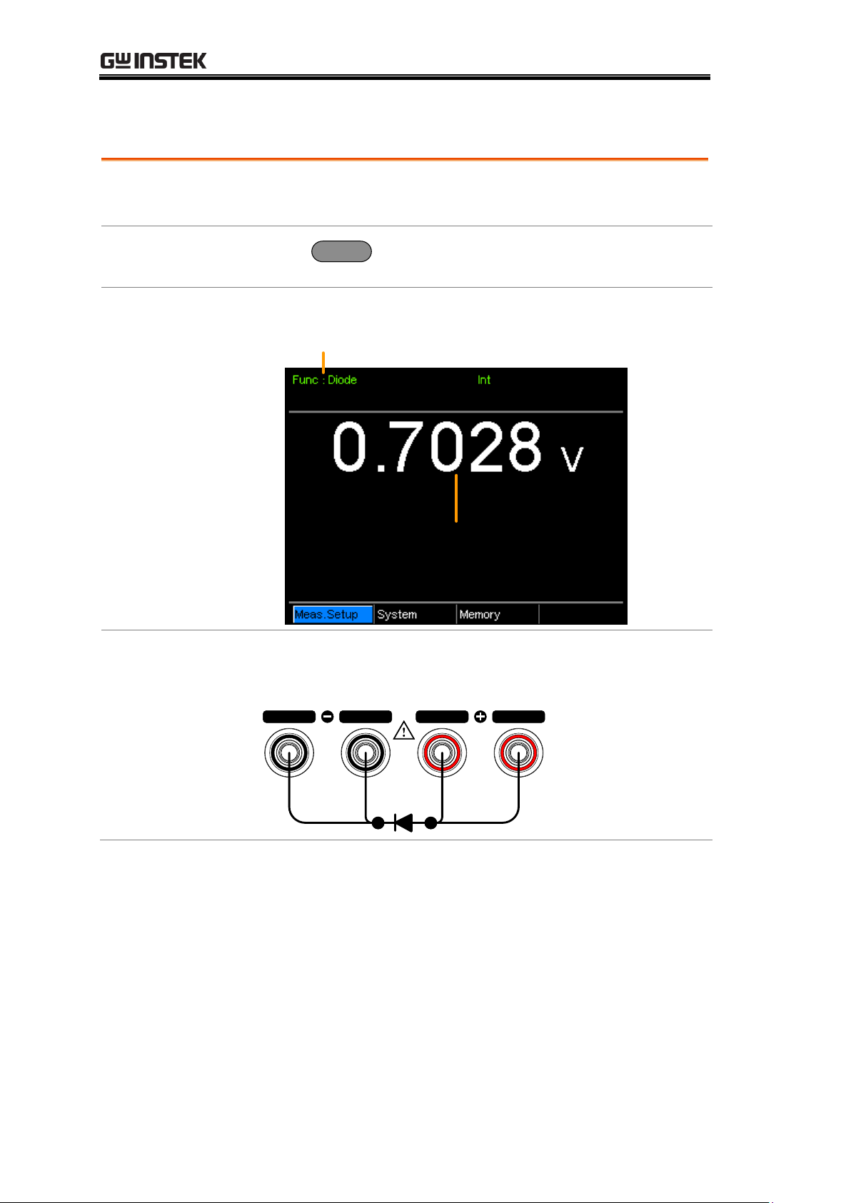
2. Diode mode
appears.
Diode function
indicator
Forward bias voltage
3. Connect the
test lead and
measure
Connect the Sense+, Source+ to the anode.
Connect the Sense-, Source- to the cathode.
SOURCE SENSE SENSE
SOURCE
GOM-804 & GOM-805 User Manual
40
Page 41
Compare Function
Background
The compare function compares a measured value to a
“Reference” value that has an upper (HI) and lower (LO)
limit. If the measured value is within the upper and lower
limit, then the measured value is judged as IN.
There are three compare modes that can be used to make
a judgment: ABS, △% and % modes.
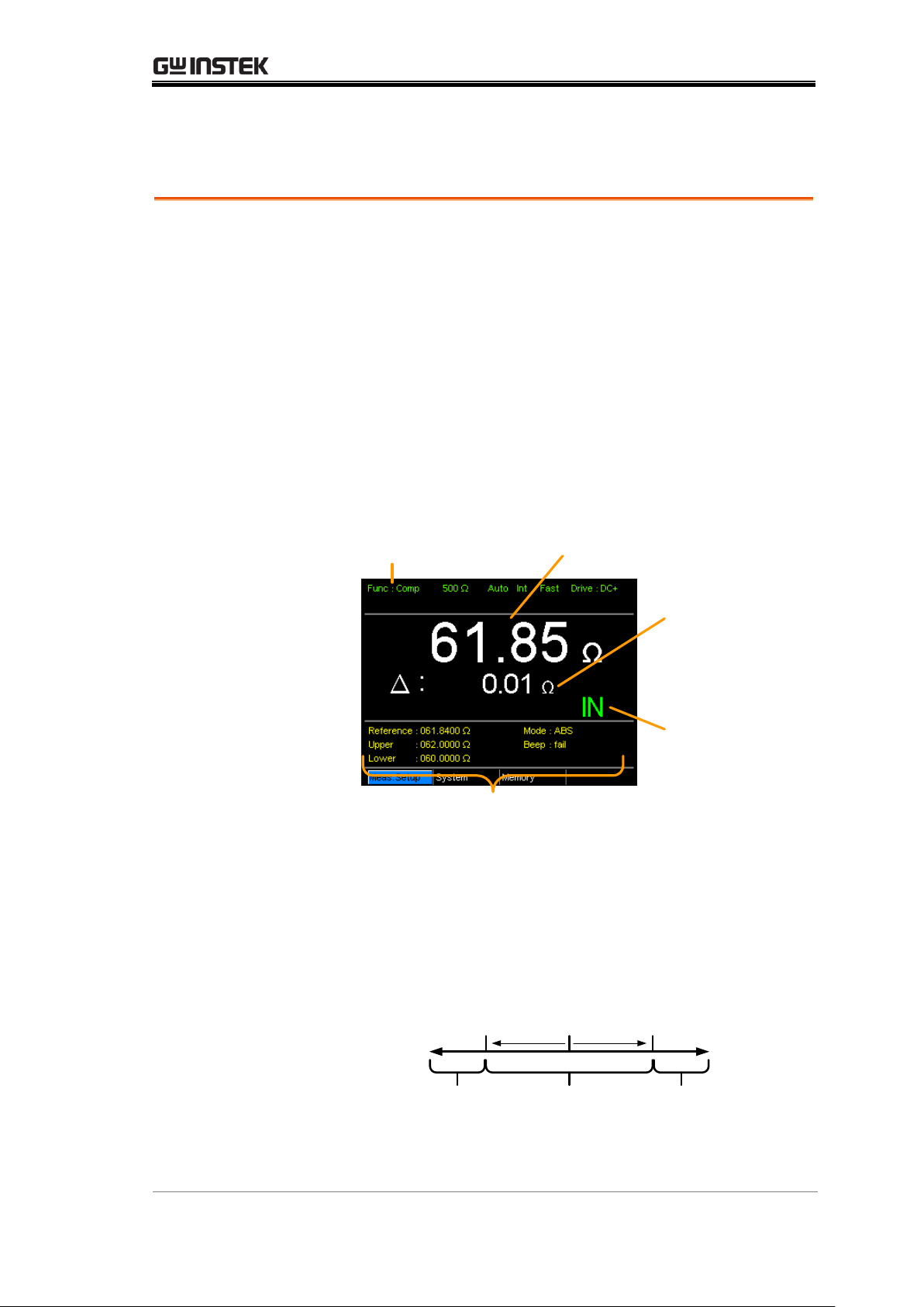
The ABS mode displays the absolute difference between
the measured and the reference value (shown as △) and
compares the measured value to the upper (HI) and
lower (LO) limit. The upper and lower limits are set as
absolute resistance values.
Compare function
indicator
Absolute
difference of
measured value
from Reference
value
Measured value
Reference, limits, compare
mode and beep mode
Pass/Fail
judgment
A measured value that falls within the upper and lower
limits is considered IN (pass), a value that falls below the
lower limits is considered LO, and a value that falls over
the upper limit is a HI.
Reference
value
Upper
limit
Lower
limit
IN HILO
[Note that the reference value in the ABS mode is only
for reference purposes and is not used to make a
judgment.]
MEASUREMENT
41
Page 42
GOM-804 & GOM-805 User Manual
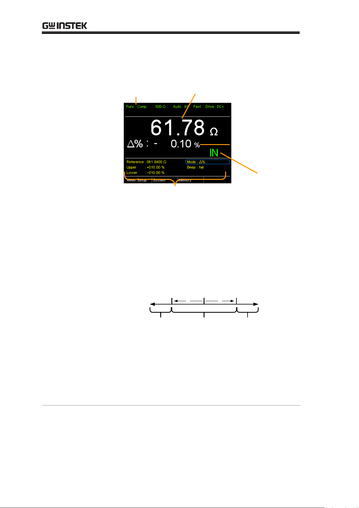
The △% compare function displays the deviation of the
measured value from the reference value as a percentage.
{ [(Measured Value-Reference)/Reference]%}.
Compare function
indicator
Deviation of the
measured value from
the reference value as
a percentage
Measured value
Reference, limits, compare
mode and beep mode
Pass/Fail judgment
The upper (HI) and low (LO) limits are set as a
percentage from the reference value. (Identical to the %
compare mode)
A measured value that falls within the upper and lower
limits is considered IN (pass), a value that falls below the
lower limits is considered LO, and a value that falls over
the upper limit is a HI.
Reference
value
Upper
limit
Lower
limit
IN HILO
%
%
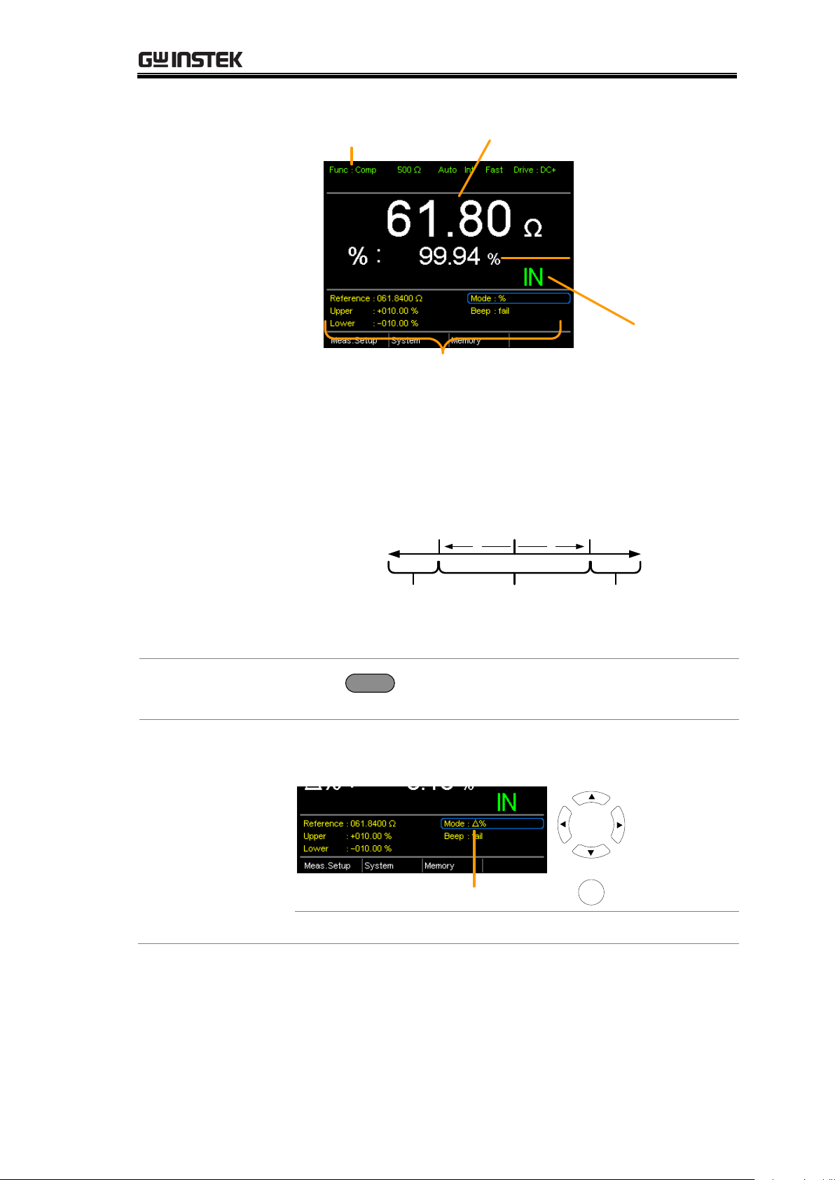
The % compare mode displays the measured value as a
percentage of the reference value [(Measured
Value/Reference Value)%].
The upper (HI) and low (LO) limits are set as a
percentage from the reference value. (Identical to the △
% compare mode)
42
Page 43
MEASUREMENT
Compare function
indicator
Measured value as a
percentage of the
reference value
Measured value
Reference, limits, compare
mode and beep mode
Pass/Fail judgment
A measured value that falls within the upper and lower
limits is considered IN (pass), a value that falls below the
lower limits is considered LO, and a value that falls over
the upper limit is a HI.
Reference
value
Upper
limit
Lower
limit
IN HILO
%
%
For all the compare modes, IN, HI or LO will be shown
on the display for each judgment.
1. Select the
compare function
Press
Compare
to access the compare mode, as shown
above.
2. Select the
compare mode
Use the arrow keys to navigate to the Mode setting. Press
the Enter key to toggle the compare mode.
Mode
Move
Toggle
Enter
Range
Abs,△ %, %
43
Page 44
GOM-804 & GOM-805 User Manual
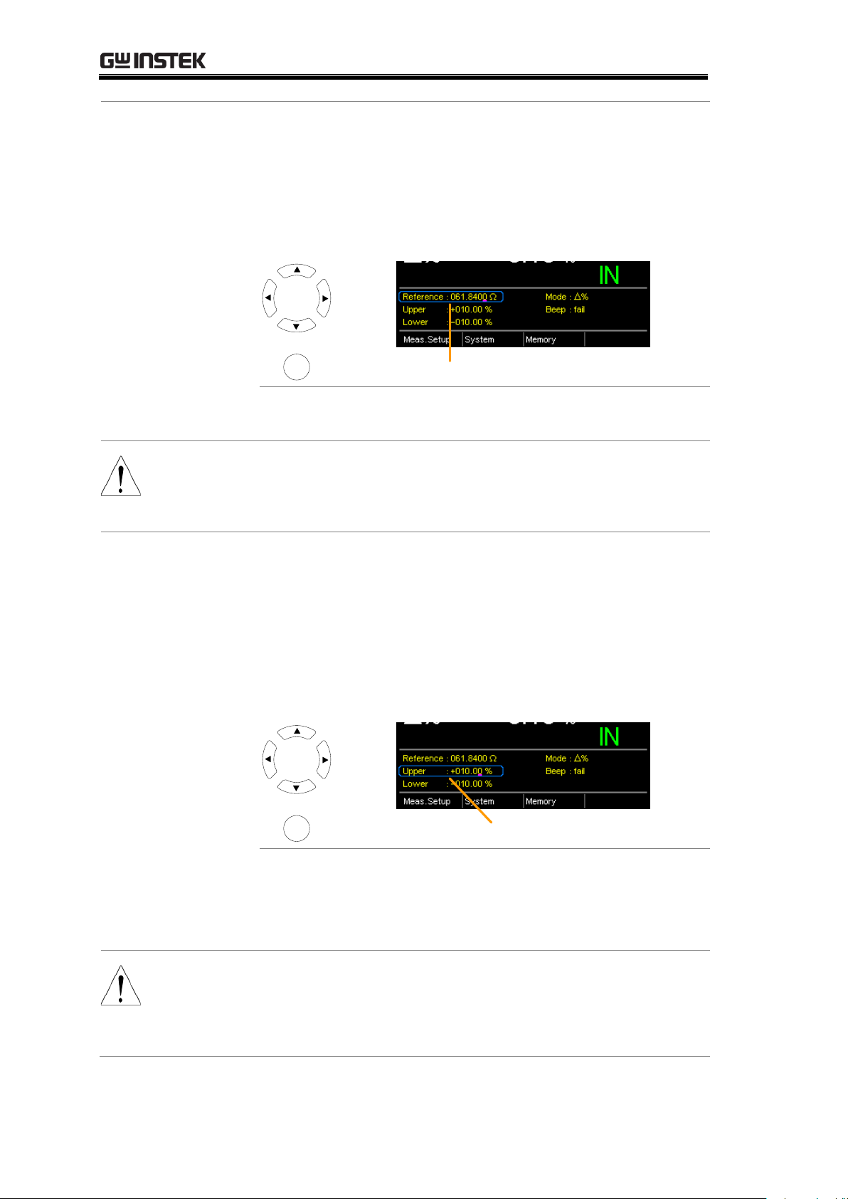
3. Reference
value setting
Use the arrow keys to navigate to the Reference setting
and press Enter.
Use the left and right arrow keys to select a digit. Use the
up and down arrow keys to edit the value of the selected
digit and the unit. Press Enter to confirm the setting.
Reference
Move
and edit
Select and
confirm
Enter
Range:
000.0001~ 999.9999
(mΩ/Ω/kΩ/MΩ)
Note
After setting the Reference value, the displayed △, % or
△% values will be changed to reflect the new Reference
value setting.
4. Upper & lower
limit setting
Use the arrow keys to navigate to the Upper or Lower
limit setting and press Enter.
Use the left and right arrow keys to select a digit. Use the
up and down arrow keys to edit the value of the selected
digit. Press Enter to confirm the setting.
Repeat for the other limit (Upper or Lower).
Upper, Lower reference
Move
and edit
Select and
confirm
Enter
Setting Range:
ABS mode: 000.0000~999.9999
(mΩ/Ω/kΩ/MΩ)
△% and % mode:
-999.99 ~ +999.99
Note
The upper limit must be higher than the lower limit. Not
setting the upper limit higher than the lower limit is not
allowed. Likewise the lower limit cannot be set higher
than the upper limit.
44
Page 45
MEASUREMENT
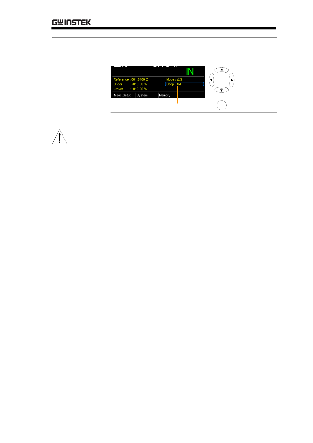
5. Beep setting
Use the arrow keys to navigate to the Beep setting.
Press Enter to toggle the beep setting.
Beep setting
Move
Toggle
Enter
Beep Setting:
Off, Pass, Fail
Note
The Beep setting can also be set from the
System>Utility>Beep>Compare menu.
45
Page 46
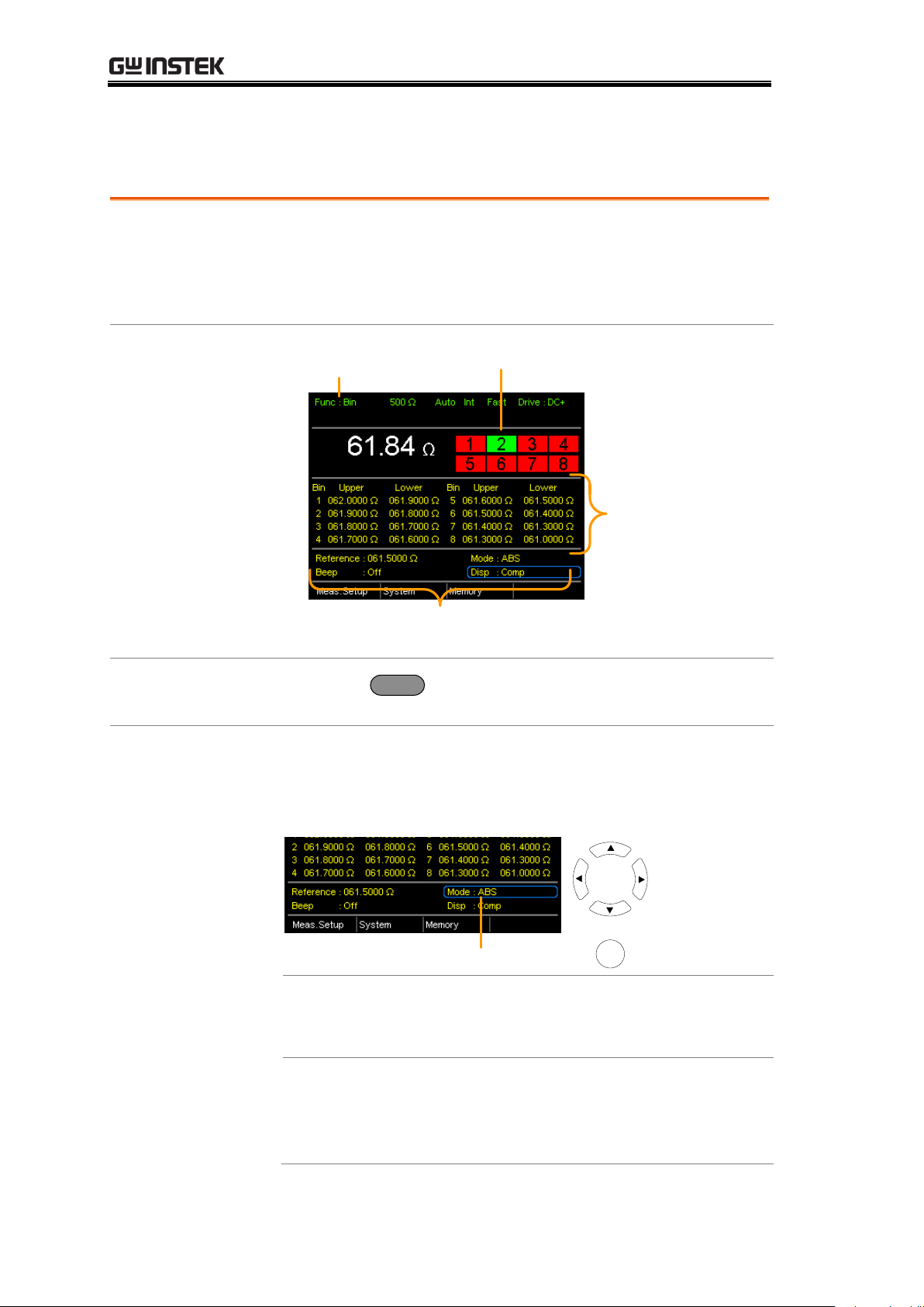
Binning Function
Background
The Binning function is used to grade DUTs into eight
different bins according to 8 sets of upper and lower
limits. Two compare modes can be used in this function,
ABS and △% modes.
Binning function
indicator
Upper and lower
limits for the 8
bins
Grading results
Reference, compare mode, beep
mode and display mode
1. Select the
Binning function
Press the
Binning
key to access this function.
2. Select the
compare mode
Use the arrow keys to go to the Mode setting.
Press Enter to toggle between ABS or △% compare
modes.
Mode setting
Move
Toggle
Enter
ABS Mode
The ABS mode allows you to set
the upper and lower limits of each
bin as absolute resistance values.
△ %
The Delta % mode allows you to
set the upper and lower limits of
each bin as percentage valu e from
the reference value.
GOM-804 & GOM-805 User Manual
46
Page 47
MEASUREMENT
Note
For further details on the ABS or △% compare modes,
see the description in the Compare section, page 41.
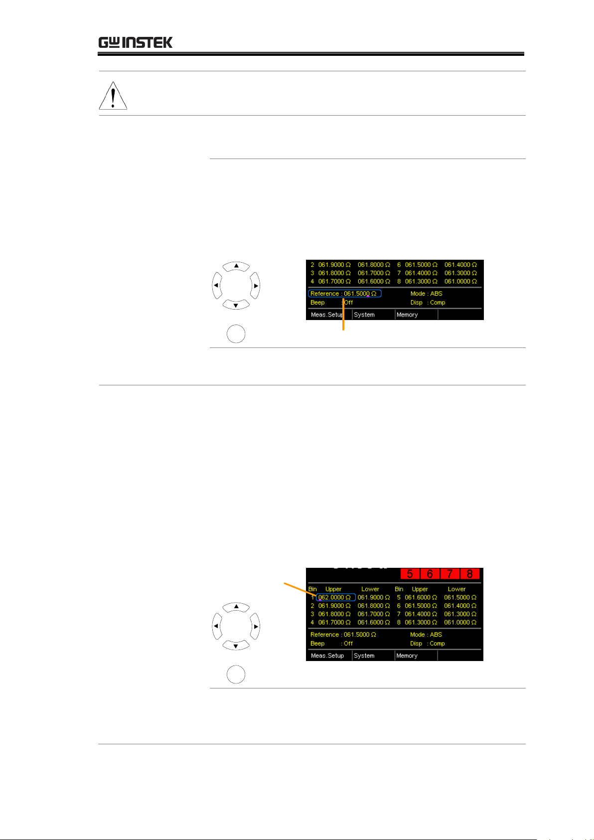
3. Reference
value setting
Although the 8 bins have their own upper and lower
limits, they still share a common reference value.
Use the arrow keys to go to the Reference setting and
press Enter.
Use the left and right arrow keys to select a digit. Use the
up and down arrow keys to edit the value of the selected
digit and the unit. Press Enter to confirm the setting.
Reference
Move
and edit
Select and
confirm
Enter
Range
000.0001~
999.9999(mΩ/Ω/kΩ/MΩ)
4. Upper & lower
limit settings
Use the arrow keys to go to the upper limit of the first
bin and press Enter.
Use the Left and Right arrow keys to select a digit. Use
the Up and Down arrow keys to edit the value of the
selected digit and unit. Press the Enter key to confirm the
setting.
Repeat for the lower setting.
Repeat for the remaining bins.
Upper, lower
reference
Move
and edit
Select and
confirm
Enter
Setting range
ABS mode: 000.0000~999.9999
(mΩ/Ω/kΩ/MΩ)
△% mode: -999.99 ~ +999.99
47
Page 48
GOM-804 & GOM-805 User Manual
Note
The upper limit must be higher than the lower limit. Not
setting the upper limit higher than the lower limit is not
allowed. Likewise the lower limit cannot be set higher
than the upper limit.
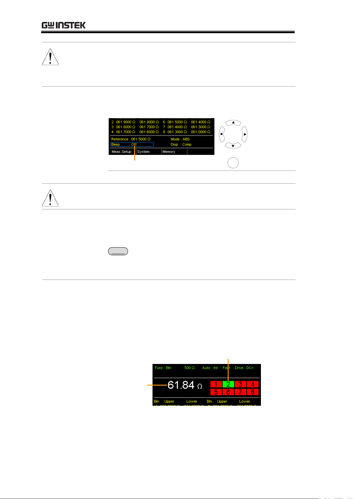
5. Beep setting
Use the arrow keys to navigate to the Beep setting.
Press Enter to toggle the beep setting.
Beep setting
Move
Toggle
Enter
Beep Setting:
Off, Pass, Fail
Note
The Beep setting can also be set from the
System>Utility>Beep>Binning menu.
6. To start
binning
The binning function starts automatically if you are in
internal trigger mode.
If you are using the manual triggering mode, press the
Trigger
button or apply a pulse on the trigger pin of the
Handler interface to start binning.
See page 38 to set the triggering modes.
7. Display the
binning results
There are two different display modes to view results.
The Comp (Compare) display mode is the default display
mode. This mode will display the currently measured
value and displays which of the bins (if any) the
measured value is graded as.
Measurement
Grading results:
Green = IN
Red = OUT
48
Page 49
MEASUREMENT
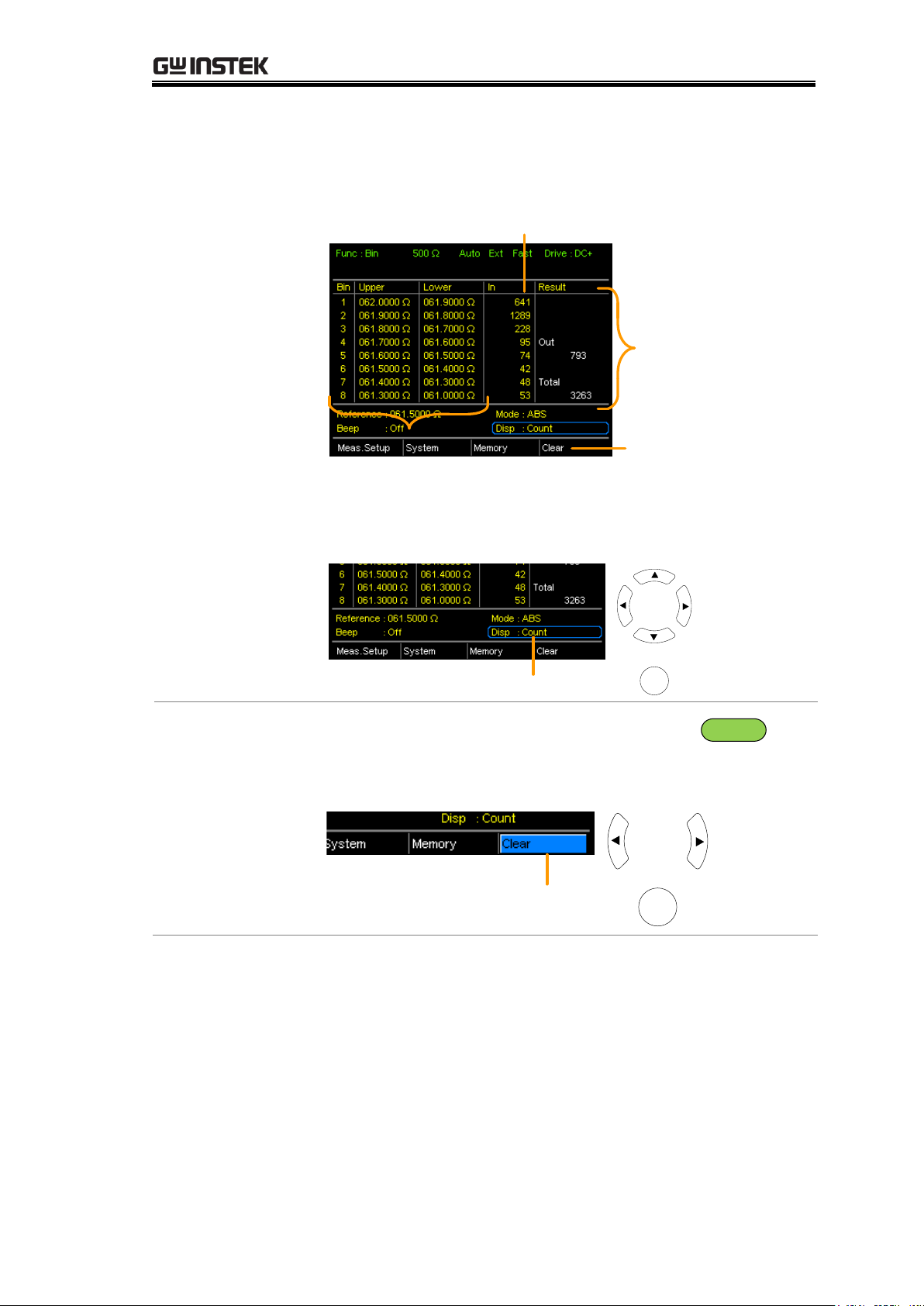
The Count display mode tabulates the results on the
right-hand side of the display and shows the bin settings
on the left.
Overall
results
Tabulated result
of each bin
Upper and lower limits of Bin 1~8
Clear
results
To toggle the display mode, go to the Disp setting and
press Enter.
Disp setting
Move
Toggle
Enter
8. How to clear
the result count
When in the Count display mode, press the
ESC
key.
Go to the Clear setting and press Enter. The accumulated
results will be cleared from the display.
Clear setting
Move
Clear results
Enter
49
Page 50
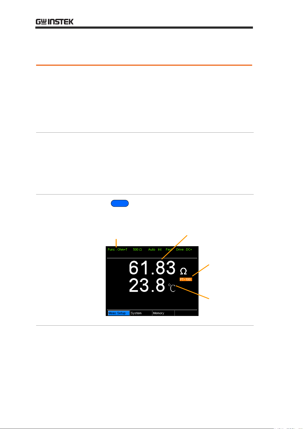
GOM-804 & GOM-805 User Manual
Background
The temperature measurement function uses the optional
PT-100 temperature probe. The measured temperature is
displayed on the display. For more information on the
optional PT-100 sensor, see the appendix on page 149.
There is only one range for the temperature function.
However the resistance measurement range can still be
changed when in the temperature function.
Note:
The temperature measurement function is used in
conjunction with the Ohm measurement function. The
two measurements share the same display, so the Ohm
readings stay on the display even after the temperature
measurement function is activated. Thus when the
Temperature function is selected, “Ohm+T” is shown as
the selected function.
1. Select the
Temperature
function
Press
TEMP
to enter the temperature measurement
function.
Temperature + Ohm
function indicator
(Ambient)
temperature
source
Resistance measurement
Ambient
temperature
The temperature is displayed on the Ohm display.
2. Select the
temperature
units
From the bottom menu, go to Meas. Setup>Temperature
Unit and select ºC or ºF.
See page 65 for setting details.
Temperature Measurement
50
Page 51
MEASUREMENT
3. Ambient
Temperature
The Ambient temperature setting should be turned off
when using the temperature function.
From the bottom menu go to Meas. Setup > Ambient
Temperature and turn the Ambient Temperature setting
off.
See page 66 for setting details.
4. Temperature
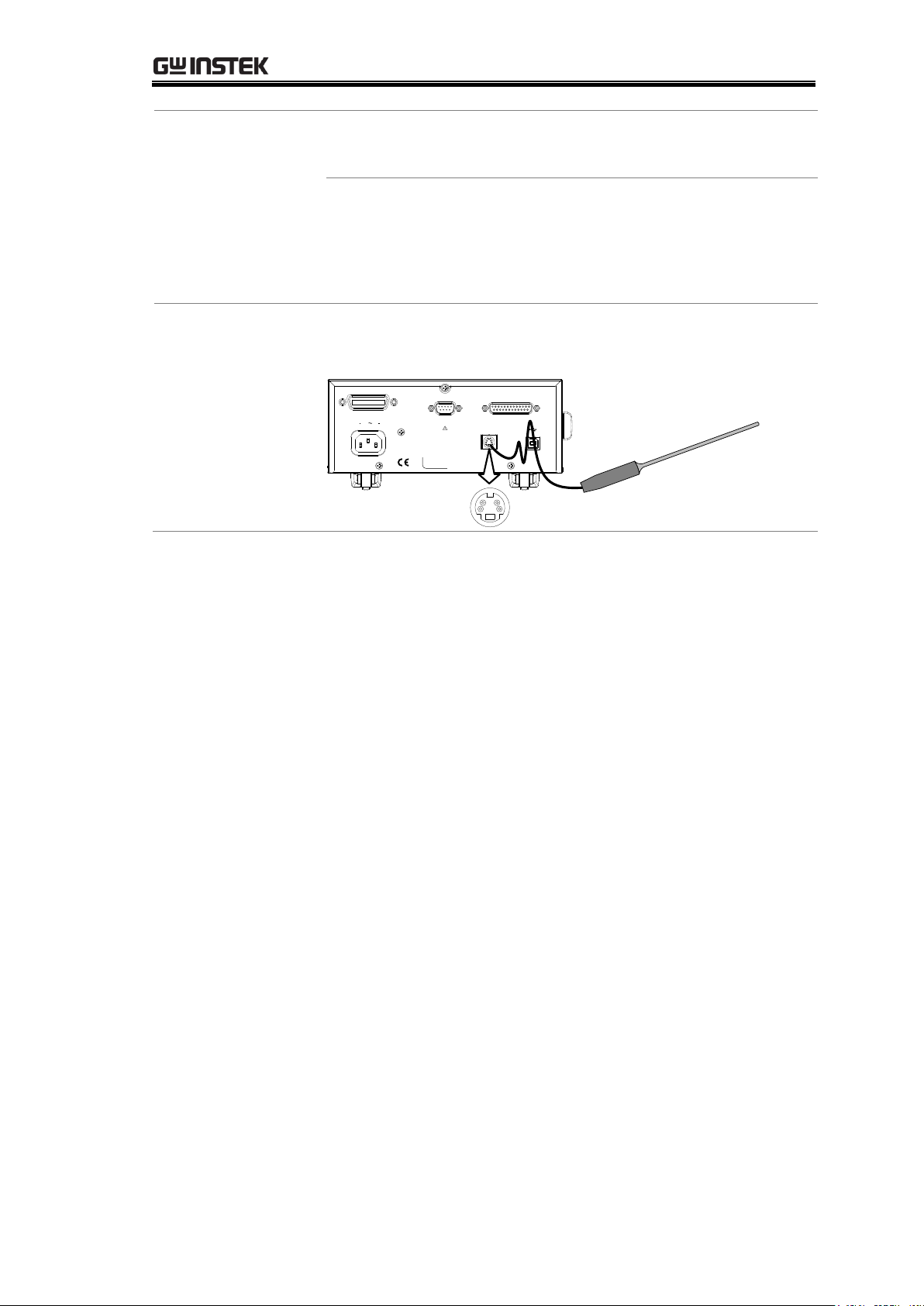
mode
connection
The temperature sensor uses the rear panel TC Sensor
port for input.
REMOVE INPUTS BEFORE OPENING.
TO AVOID SHOCK,
WARNING
RS232
SER.NO. LABEL
100 240V , 50 60Hz
25VA MAX
AC
HANDLER / SCAN / EXT I/O
TC SENSOR
GPIB
PT-100 temperature
sensor
51
Page 52
GOM-804 & GOM-805 User Manual
Background
If the resistance of a DUT at a particular temperature is
needed, the compensation function can be used. This
function can simulate the resistance of a DUT at a
desired temperature. If the ambient temperature and the
temperature coefficient of the DUT are known, it is
possible to determine the resistance of a DUT at any
temperature.
The Temperature Compensation works on the following
formula:
)(1 000t-tα
R
R
t
t
t
Where:
Rt = Measured resistance value (Ω)
Rt0 = Corrected resistance value (Ω)
T0 = Inferred absolute temperature
t0 = Corrected temperature (ºC)
t = Current ambient temperature (ºC)
αto = Temperature coefficient of resistance at the correct
temperature.
00 |
1
tT|
ato
.
Temperature Compensation
52
Page 53
MEASUREMENT
1. Select the
Temperature
Compensation
mode
Press
TC
to access the Temperature Compensation
function.
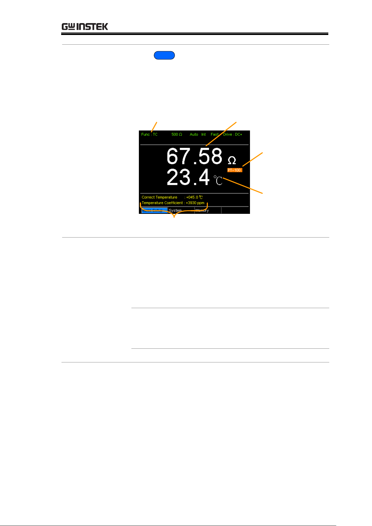
The temperature-compensated resistance measurement
will appear on the display.
Temperature
compensation
function indicator
Ambient
temperature
source
Extrapolated resistance
measurement at the desired
(“correct”) temperature
Correct Temperature,
Temperature Coefficient settings
Ambient
temperature
2. Ambient
Temperature
The ambient temperature can be either measured with
the PT-100 sensor or be set manually.
If using the PT-100 sensor the Ambient temperature
setting should be turned off. If the PT-100 probe is not
used, then the ambient temperature needs to be manually
set.
From the bottom menu, go to Meas. Setup > Ambient
Temperature and set the ambient temperature.
See page 66 for setting details.
Range
Off, -50.0 ºC ~ 399.9ºC
53
Page 54
GOM-804 & GOM-805 User Manual
3. Temperature
compensation
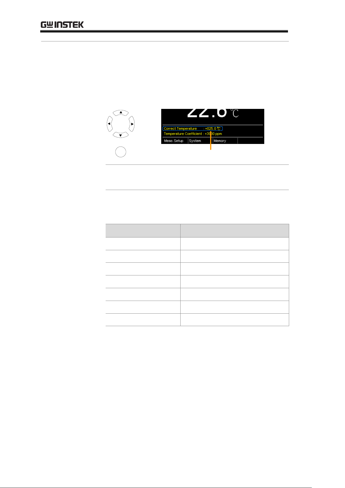
Use arrow keys to go to Correct Temperature or to
Temperature Coefficient and press Enter to select the
setting.
To edit the setting values use the left and right arrow keys
to select a digit and use the up and down arrow keys to
edit the digit. Press Enter to confirm the setting.
Correct temperature, temperature
coefficient settings
Move
and edit
Select and
confirm
Enter
Desired Temperature range
-50.0 ~ +399.9 ˚C
Temperature Coefficient range
-9999 ~ +9999 ppm
Below are the inferred zero resistance temperatures of
some common conductors:
Material
Inferred Absolute Temperatures
Silver
-243
Copper
-234.5
Gold
-274
Aluminium
-236
Tungsten
-204
Nickel
-147
Iron
-162
54
Page 55
MEASUREMENT
3. Temperature
compensation
connection
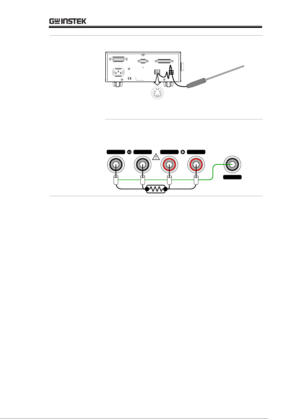
Sensor Connection:
REMOVE INPUTS BEFORE OPENING.
TO AVOID SHOCK,
WARNING
RS232
SER.NO. LABEL
100 240V , 50 60Hz
25VA MAX
AC
HANDLER / SCAN / EXT I/O
TC SENSOR
GPIB
PT-100 temperature
sensor
Note: If the sensor is not connected, then the Ambient
temperature needs to be manually set.
DUT connection:
4 wire Kelvin:
GUARD
SOURCE SENSE SENSE
SOURCE
shielding
55
Page 56
Background
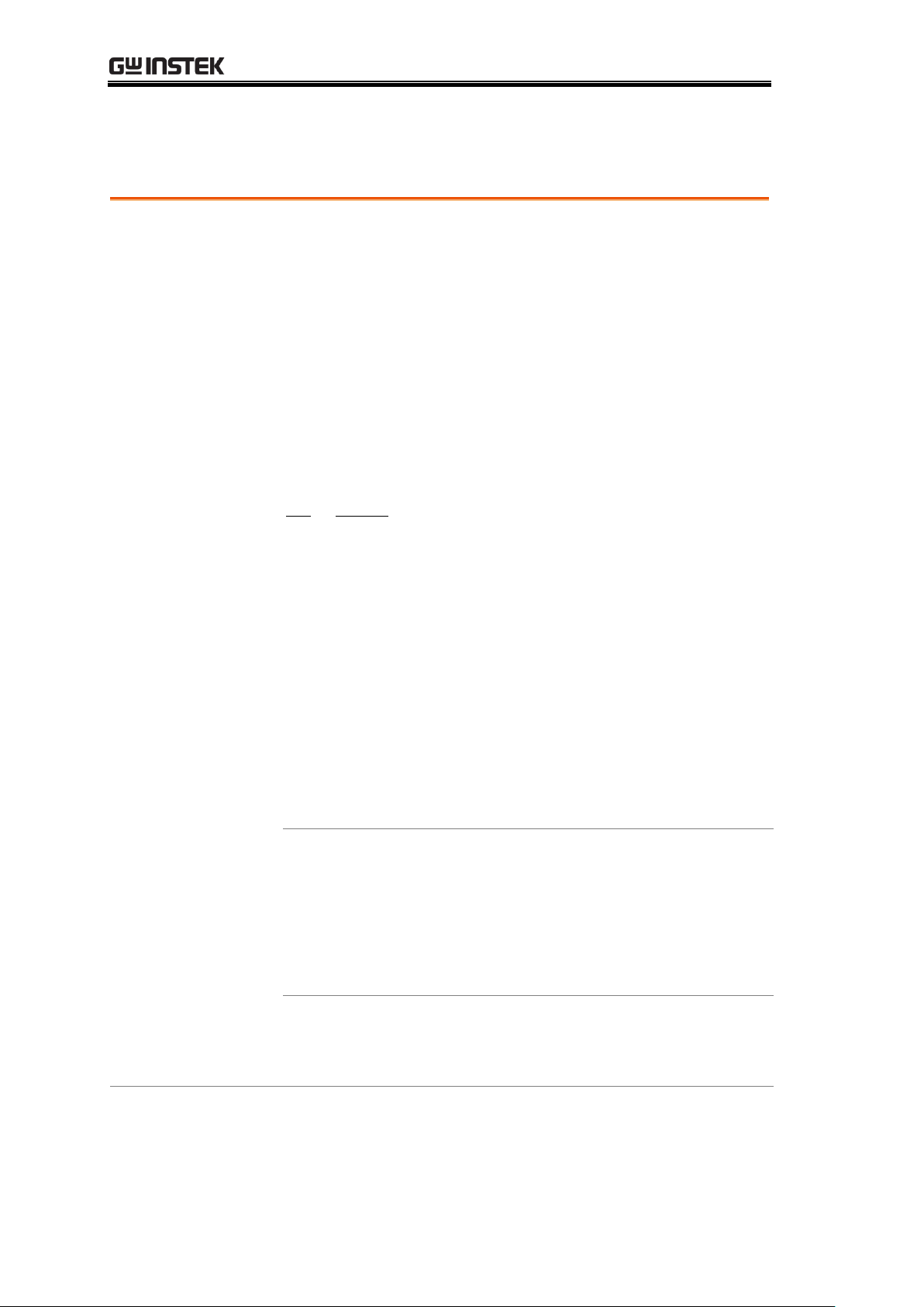
The Temperature Conversion function allows you to
determine the temperature change of a DUT at any given
resistance, if the initial temperature, the inferred zero
resistance temperature for the DUT and the initial
resistance of the DUT are known. The displayed result
can also be the extrapolated to calculate the final
temperature (T) or the extrapolated temperature
difference (△T)*.
Temperature Conversion function works on the following
formula:
10
20
1
2
tt
tt
R
R
Where:
R2 = resistance @ temperature t2
R1 = resistance @ temperature t1
t0 = inferred zero resistance temperature in ºC**
t1 = temperature at R
1
t2 =temperature at R2
The temperature conversion function is can be used to
determine the temperature of transformer windings,
electric motors, or other materials where it may not be
practical to embed a temperature sensor.
*(T) Final temperature = t2 = △T +T
A
(TA) Ambient temperature = Ambient temperature when
R2 is measured. TA can either by manually measured with
the PT-100 sensor or it can be manually set.
(△T) Extrapolated temperature difference = T - T
A
**“Constant” setting on the panel display is equivalent to
the absolute value of the inferred zero resistance
temperature.
GOM-804 & GOM-805 User Manual
Temperature Conversion
56
Page 57
MEASUREMENT
Common inferred
zero resistance
temperatures
Metallic conductors show increased resistivity when
temperature is increased, and likewise show reduced
resistivity when temperature is reduced. Inferred zero
resistance temperature is simply the inferred temperature
at which the material will have no resistance. This value is
derived from the temperature coefficient of the material.
Note: the inferred zero resistance temperature is an ideal
value, and not a real-world value.
Material
Inferred zero resistance temp. in ºC
Silver
-243
Copper
-234.5
Gold
-274
Aluminium
-236
Tungsten
-204
Nickel
-147
Iron
-162
1. Select the
Temperature
compensation
mode.
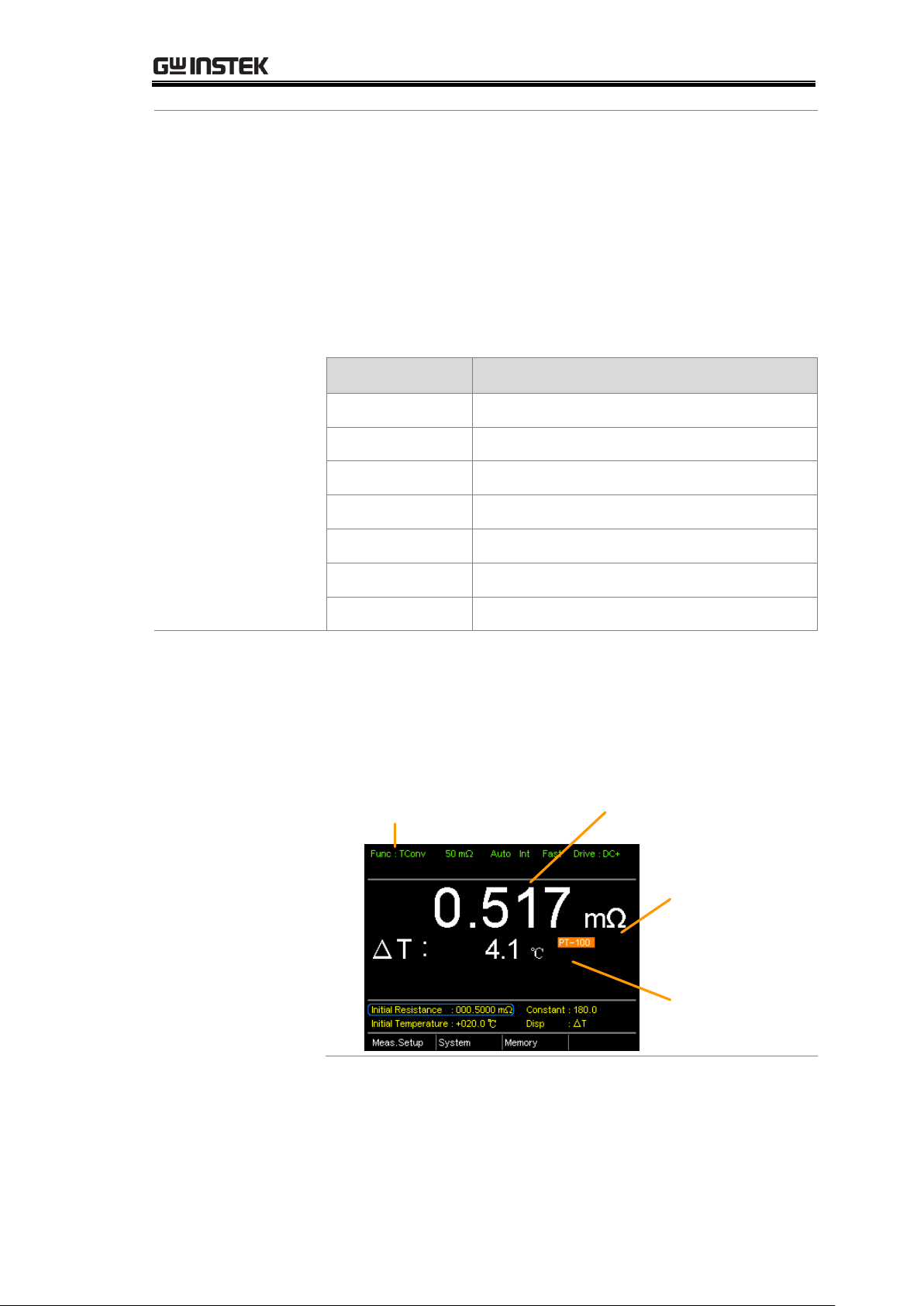
Press TCONV to access the temperature compensation
function.
The temperature-converted measurement will appear on
the display.
Temperature
conversion function
indicator
(Ambient)
temperature
source
Resistance measurement
Extrapolated
temperature
difference or final
temperature
57
Page 58
GOM-804 & GOM-805 User Manual
2. Initial
Resistance,
Initial
Temperature and
Constant settings
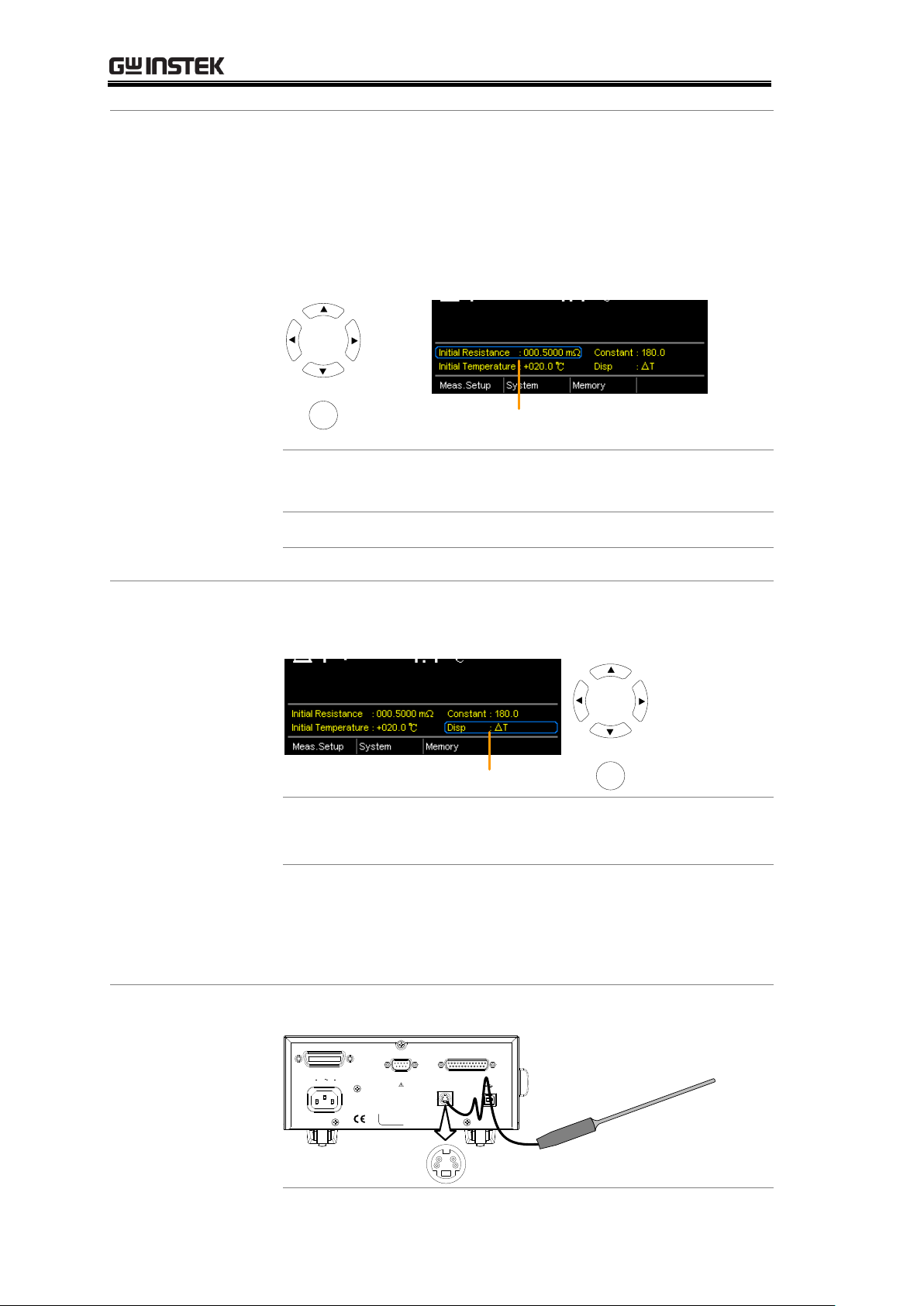
Use the arrows keys to go to Initial Resistance, Initial
Temperature or Constant (inferred initial resistance
temperature) and press Enter.
Use the left and right arrow keys to select a digit and use
the up and down arrow keys to edit the digit. Press Enter
to confirm the edit.
Initial Resistance, Initial Temperature
and Constant settings
Move
and edit
Select and
confirm
Enter
Initial Resistance
000.0001~999.9999 mΩ, Ω, kΩ,
MΩ
Initial Temperature
-50.0 ~ +399.9 ℃
Constant
000.0~999.9
3. Display mode
Use the arrow keys to go to Disp. Press Enter to toggle
between the T and △T modes.
Disp setting
Move
Toggle
Enter
T displays the extrapolated temperature at the measured
resistance of the DUT.
△T displays the difference from the extrapolated
temperature at the measured resistance of the DUT and
the ambient temperature. Please refer to page 56 for
further details.
3. Temperature
compensation
connection.
Sensor Connection:
REMOVE INPUTS BEFORE OPENING.
TO AVOID SHOCK,
WARNING
RS232
SER.NO. LABEL
100 240V , 50 60Hz
25VA MAX
AC
HANDLER / SCAN / EXT I/O
TC SENSOR
GPIB
PT-100 temperature
sensor
58
Page 59
MEASUREMENT
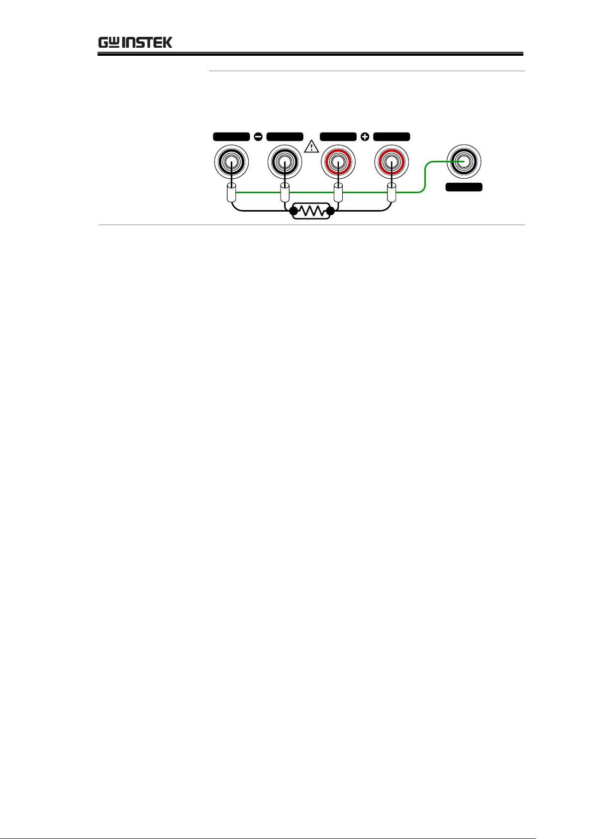
DUT connection
4 wire Kelvin:
GUARD
SOURCE SENSE SENSE
SOURCE
shielding
59
Page 60
GOM-804 & GOM-805 User Manual
Background
The following measurement settings are used to
configure the various measurement modes.
Background
The average function smoothes measurements using a
moving average. The average function sets the number of
samples used for the moving average; a higher number
results in smoother measurement results. The average
function is turned off by default.
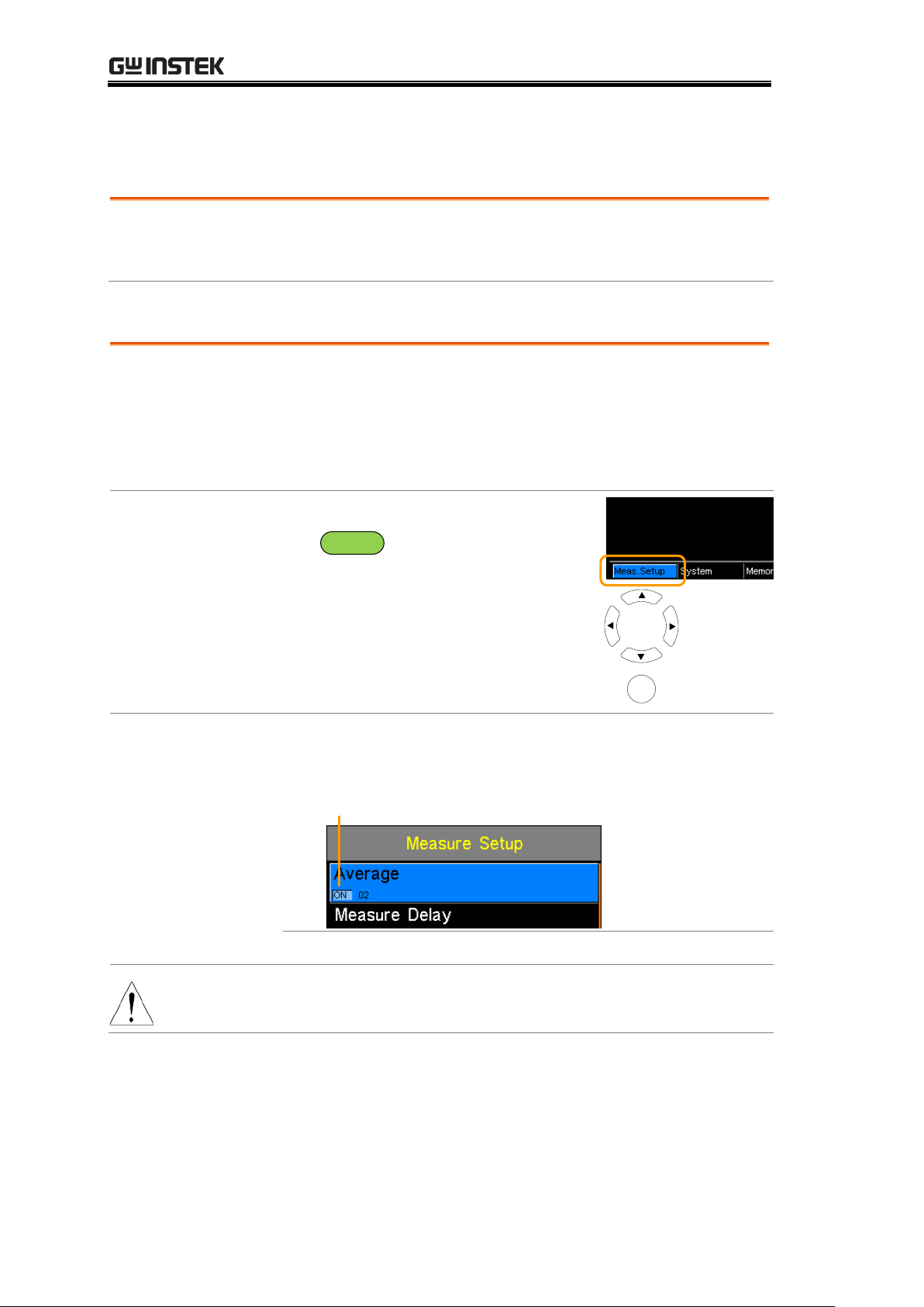
1. Select Average
setting
From one of the main screens, press
the
ESC
key so that the menu
system at the bottom of the display
has focus.
Go to Meas. Setup and press Enter.
Go to Average and press Enter.
Meas. Setup
menu icon
Move
Select menu
or setting
Enter
2. Average
setting appears
Use the arrow keys to turn Average on and set the
average number. Press Enter to confirm the setting.
Average settings
Average
OFF, ON: 2~10
Note
Pressing ESC before pressing ENTER will exit the Average
function settings.
Measurement Settings
Average Function
60
Page 61
Measure Delay
Background
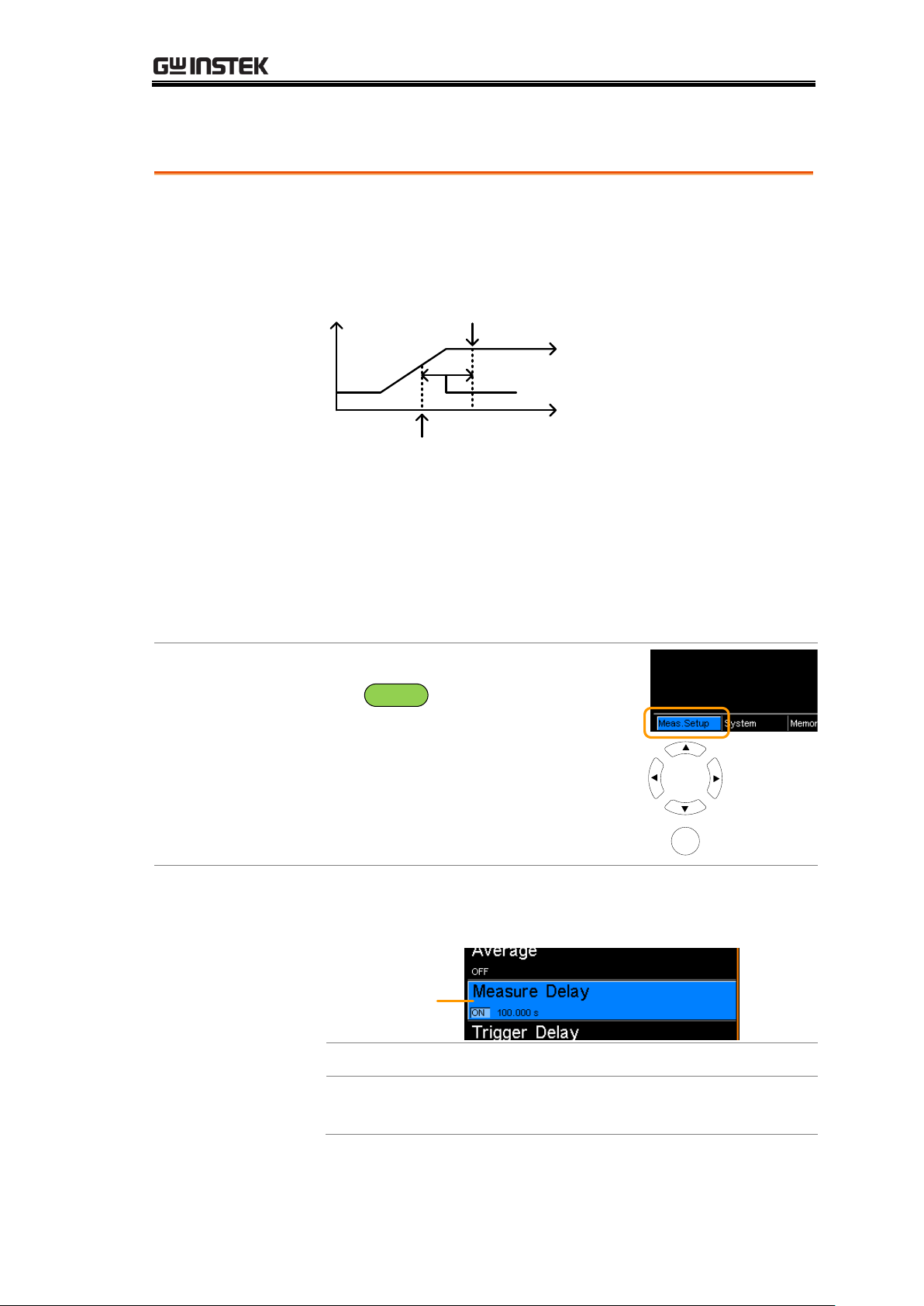
The Measure Delay setting inserts a delay time between
each measurement. Measure delay is turned off by
default.
Test signal
Default Measurement
start time
Measurement start with
Measure delay time
Measure delay time
The measure delay setting is useful for measuring
components that need some time to charge if the default
measurement start time is not adequate. An adequate
delay time allows the meter to avoid the effects of
transient disturbances that are usually seen when
measuring reactive DUTs with a current source.
1. Select
Measure Delay
setting
From one of the main screens, press
the
ESC
key so that the menu
system at the bottom of the display
has focus.
Go to Meas. Setup and press Enter.
Go to Measure Delay and press
Enter.
Meas. Setup
menu icon
Move
Select menu
or setting
Enter
2. Measure Delay
setting appears
Use the arrow keys to turn Measure Delay on and set the
delay time. Press Enter to confirm the setting.
Measure delay
setting
Measure Delay*
OFF, ON: 000.000 ~ 100.000s
* When the set value is > 0.1s, the resolution is 0.1s.
When the set value is < 0.1S, the resolution is 1mS.
MEASUREMENT
61
Page 62
GOM-804 & GOM-805 User Manual
Note
Pressing ESC before pressing ENTER will exit the Measure
Delay settings.
62
Page 63
Trigger Delay
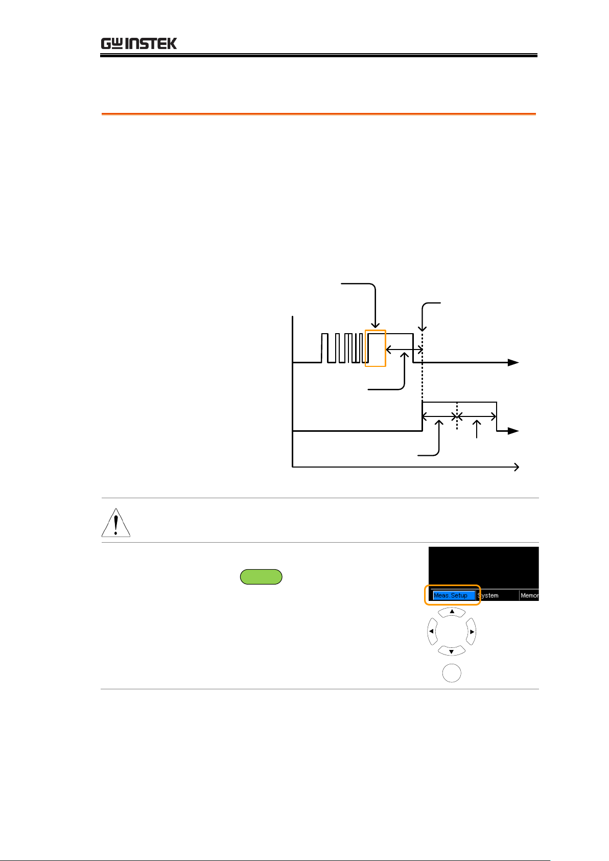
Background
The Trigger Delay setting adds a delay to when an
external trigger signal is recognized. Normally the
external trigger is recognized when there is no contact
bounce in the signal for a fixed length of time, this time
is known as the bounce monitoring window. This ensures
that the external trigger signal is stable before it is
recognized. The Trigger Delay time starts right after the
bounce monitoring window ends.
Start measurement
period
External
Trigger signal
Bounce monitoring
window
Trigger
delay time
Measurement
period
Measurement
process
Contact
bounce
Measurement
delay time
Measurement
time
The Trigger Delay setting is turned off by default.
Note
Pin 2 of the Handler/Scan/Ext I/O interface is used for
external triggering, See page 77 for pinout details.
1. Select Trigger
Delay setting
From one of the main screens, press
the
ESC
key so that the menu
system at the bottom of the display
has focus.
Go to Meas. Setup and press Enter.
Go to Trigger Delay and press
Enter.
Meas. Setup
menu icon
Move
Select menu
or setting
Enter
MEASUREMENT
63
Page 64
2. Trigger Delay
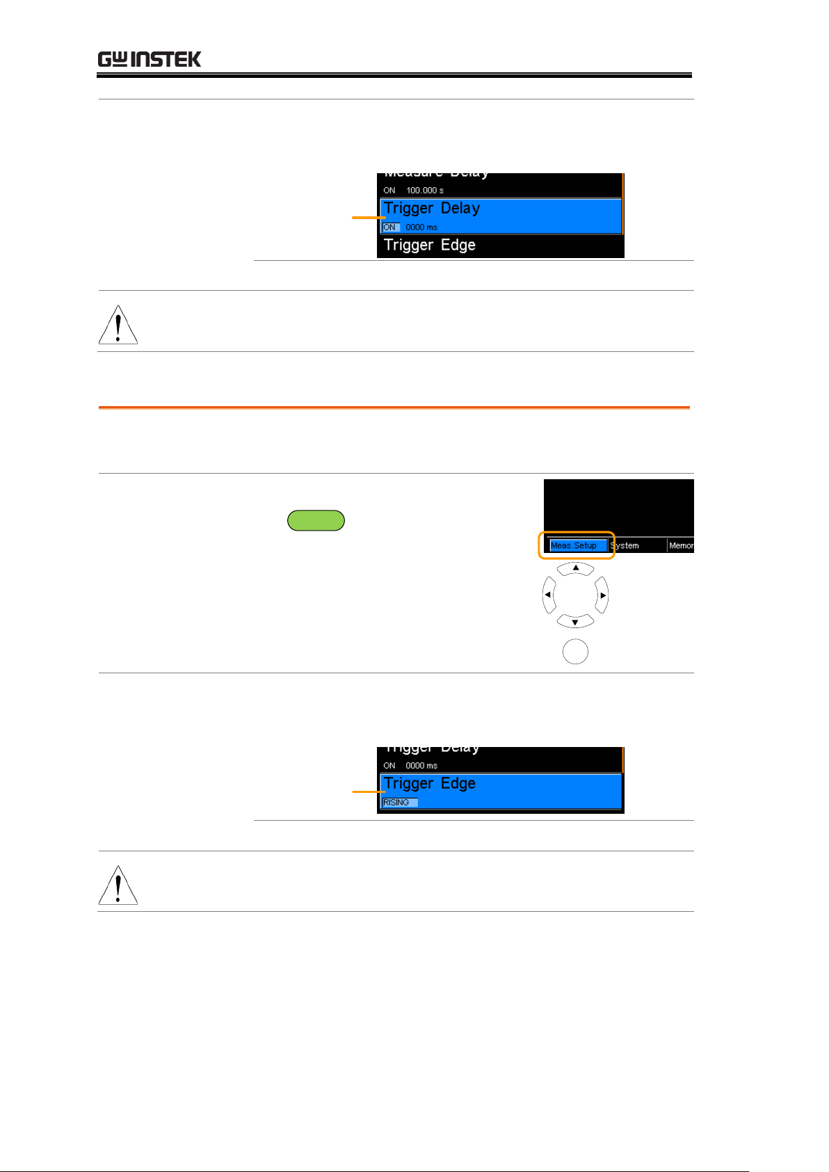
setting appears
Use the arrow keys to turn Trigger Delay on and set the
delay time. Press Enter to confirm the settings.
Trigger Delay
setting
Trigger Delay
OFF, ON: 0 ~ 1000ms
Note
Pressing ESC before pressing ENTER will exit the Trigger
Delay settings.
Trigger Edge
Background
The Trigger Edge setting sets the external trigger edge as
rising or falling. By default the trigger edge is set to rising.
1. Select Trigger
Edge setting
From one of the main screens, press
the
ESC
key so that the menu
system at the bottom of the display
has focus.
Go to Meas. Setup and press Enter.
Go to Trigger Edge and press Enter.
Meas. Setup
menu icon
Move
Select menu
or setting
Enter
2. Trigger Edge
setting appears
Use the arrow keys to set the Trigger Edge. Press Enter
to confirm the setting.
Trigger Edge
setting
Trigger Edge
Rising, Falling
Note
Pressing ESC before pressing ENTER will exit the Trigger
Edge settings.
GOM-804 & GOM-805 User Manual
64
Page 65
Temperature Unit
Background
Temperature units can be set to Fahrenheit or Celsius for
all temperature measurements.
1. Select
Temperature Unit
setting
From one of the main screens, press
the
ESC
key so that the menu
system at the bottom of the display
has focus.
Go to Meas. Setup and press Enter.
Go to Temperature Unit and press
Enter.
Meas. Setup
menu icon
Move
Select menu
or setting
Enter
2.Temperature
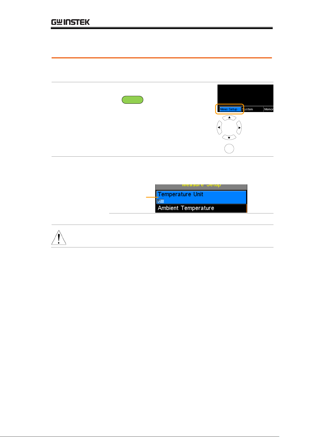
Unit setting
appears
Use the arrow keys to set the Temperature Unit. Press
Enter to confirm the setting.
Temperature
Unit
Temperature Unit
Fahrenheit, Celsius
Note
Pressing ESC before pressing ENTER will exit the
Temperature Unit setting.
MEASUREMENT
65
Page 66
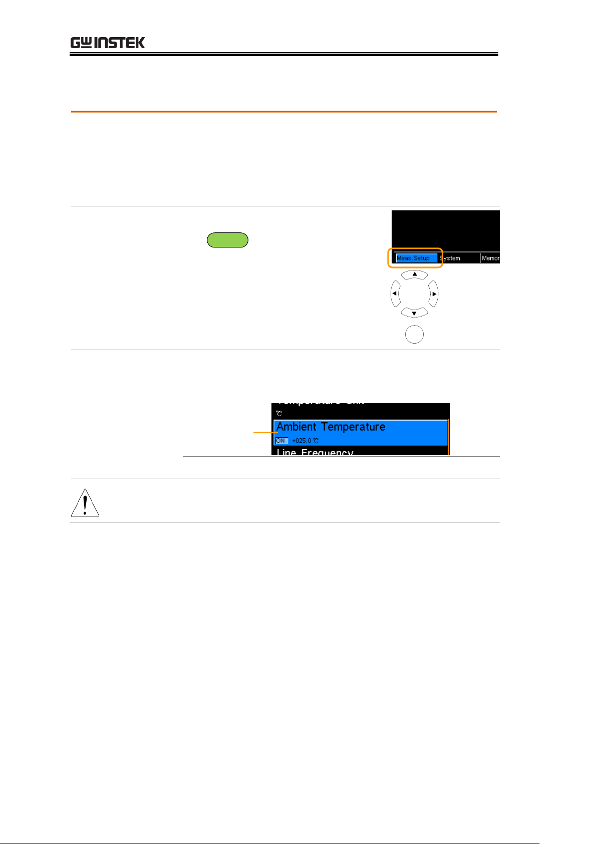
Ambient Temperature
Background
The Ambient Temperature setting is used to set the
ambient (room temperature) for the Temperature
Compensation or Temperature Conversion function in
the absence of the PT-100 temperature sensor. See page
52 and 56 respectively for details.
1. Select Ambient
Temperature
setting
From one of the main screens, press
the
ESC
key so that the menu
system at the bottom of the display
has focus.
Go to Meas. Setup and press Enter.
Go to Ambient Temperature and
press Enter.
Meas. Setup
menu icon
Move
Select menu
or setting
Enter
2.Ambient
Temperature
setting appears
Use the arrow keys to set the Ambient Temperature.
Press Enter to confirm the setting.
Ambient
Temperature
Ambient Temperature
Off, On: -50ºC ~ 399.9ºC
Note
Pressing ESC before pressing ENTER will exit the Ambient
Temperature setting.
GOM-804 & GOM-805 User Manual
66
Page 67
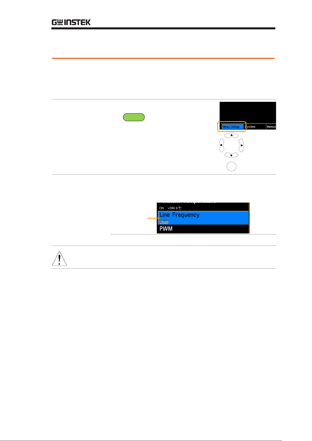
Line Frequency
Background
The Line Frequency setting selects the appropriate line
filter to reduce the influence of the AC line frequency on
the milliohm measurements. This setting is set to AUTO
by default.
1. Select Line
Frequency
setting
From one of the main screens, press
the
ESC
key so that the menu
system at the bottom of the display
has focus.
Go to Meas. Setup and press Enter.
Go to Line Frequency and press
Enter.
Meas. Setup
menu icon
Move
Select menu
or setting
Enter
2.Line Frequency
setting appears
Use the arrow keys to set the Line Frequency. Press Enter
to confirm the setting.
Line Frequency
Line Frequency
Auto, 50Hz, 60Hz
Note
Pressing ESC before pressing ENTER will exit the Line
Frequency setting.
MEASUREMENT
67
Page 68
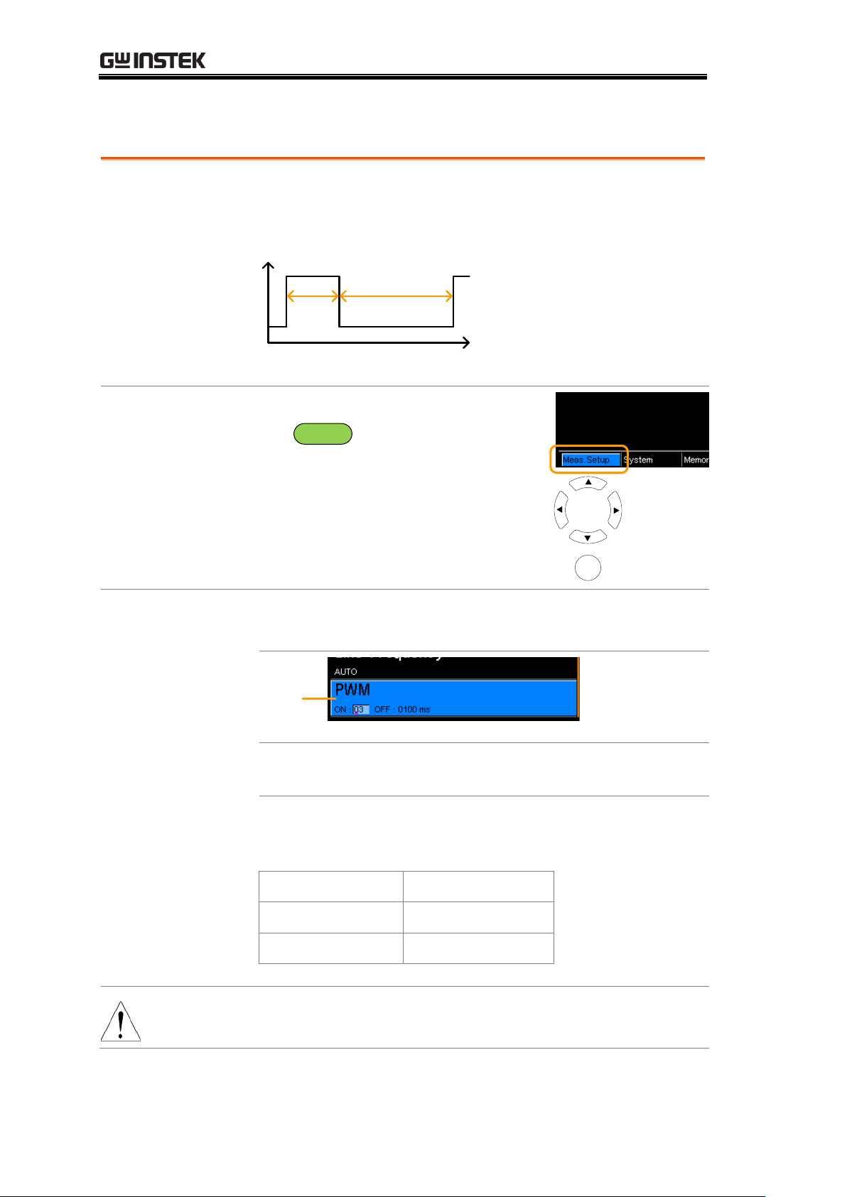
PWM Setting
Background
The PWM setting will set the duty of the PWM Drive
setting. The duty is set with ON and OFF times for the
waveform.
OFF time
ON
time
See page 31 for Drive setting details.
1. Select PWM
setting
From one of the main screens, press
the
ESC
key so that the menu
system at the bottom of the display
has focus.
Go to Meas. Setup and press Enter.
Go to PWM and press Enter.
Meas. Setup
menu icon
Move
Select menu
or setting
Enter
2.PWM setting
appears
Use the arrow keys to set the ON and OFF time for the
duty. Press Enter to confirm the setting.
PWM
ON
OFF
03 ~ 99 time units*
0100 ~ 9999 ms
*The ON time setting is set in “time units”, not
milliseconds. The amount of time in a time unit depends
on the line frequency settings (see page 67).
Line frequency
1 Time Unit
60Hz
16.6mS
50Hz
20mS
Note
Pressing ESC before pressing ENTER will exit the PWM
setting.
GOM-804 & GOM-805 User Manual
68
Page 69
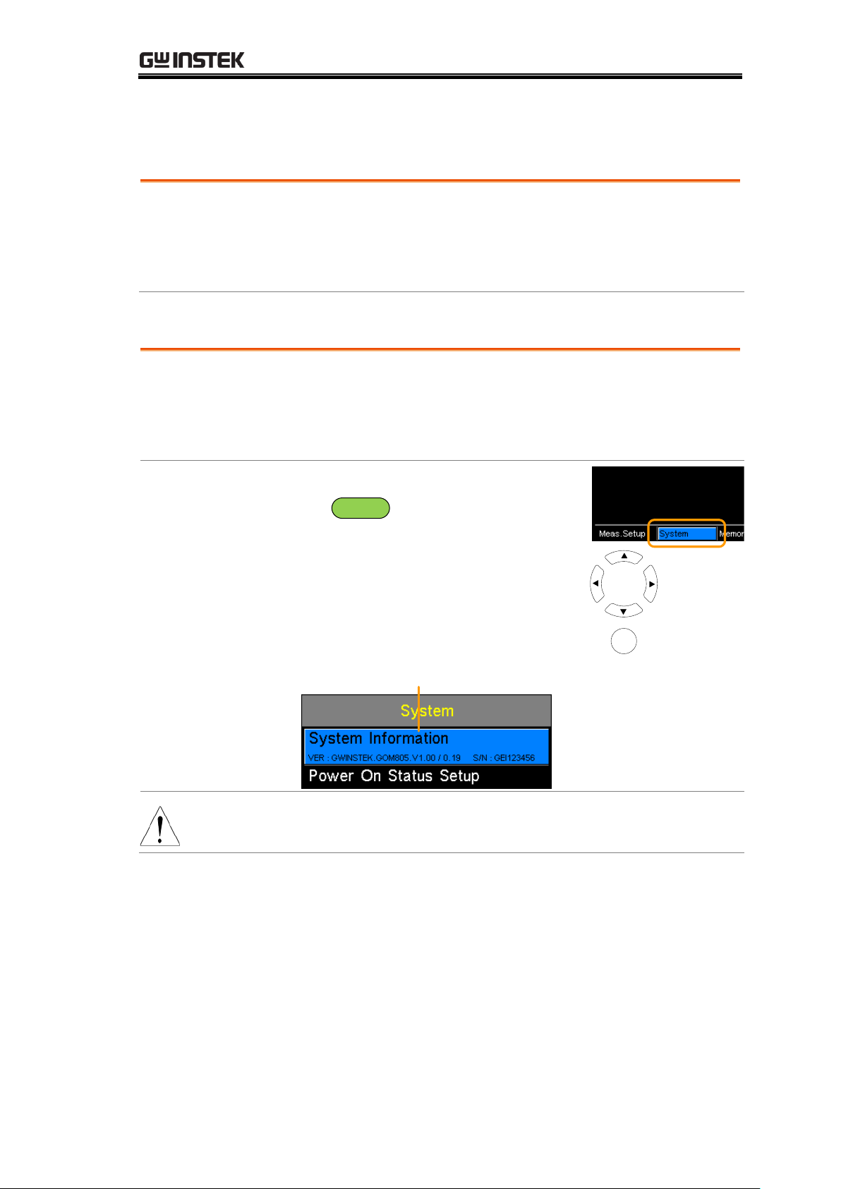
System Settings
Background
The System settings are used to view the system
information, set the power on state, the remote interface,
screen brightness, external interface and beep settings as
well as access the calibration menu.
Background
The System Information will show the manufacturer,
model, software version and serial number of the unit.
The system information is the equivalent of the return
string from the *idn? query (page 144).
1. View System
Information
From one of the main screens, press
the
ESC
key so that the menu
system at the bottom of the display
has focus.
Go to System and press Enter.
System information will be displayed
at the top of the System menu.
System
menu icon
Move
Select menu
or setting
Enter
System Information
Note
Pressing ESC will exit from the System menu.
System Information
MEASUREMENT
69
Page 70
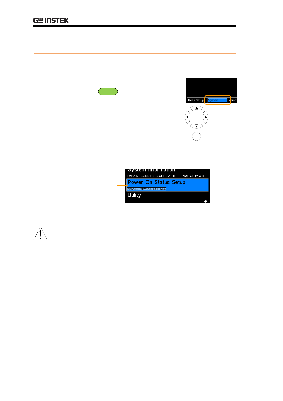
Power On Status Setup
Background
The Power On Status Setup allows you to either load the
previous settings or the default settings on startup.
1. Select Power
On Status
setting
From one of the main screens, press
the
ESC
key so that the menu
system at the bottom of the display
has focus.
Go to System and press Enter.
Go to Power On Status Setup and
press Enter.
System
menu icon
Move
Select menu
or setting
Enter
2. Power On
Status Setup
appears
Use the arrow keys to set Power ON Status Setup. Press
Enter to confirm the setting.
Power On
Status Setup
Power On Status
Recall Previous Settings,
Load Default
Note
Pressing ESC before pressing ENTER will exit the Power
On Status Setup.
GOM-804 & GOM-805 User Manual
70
Page 71
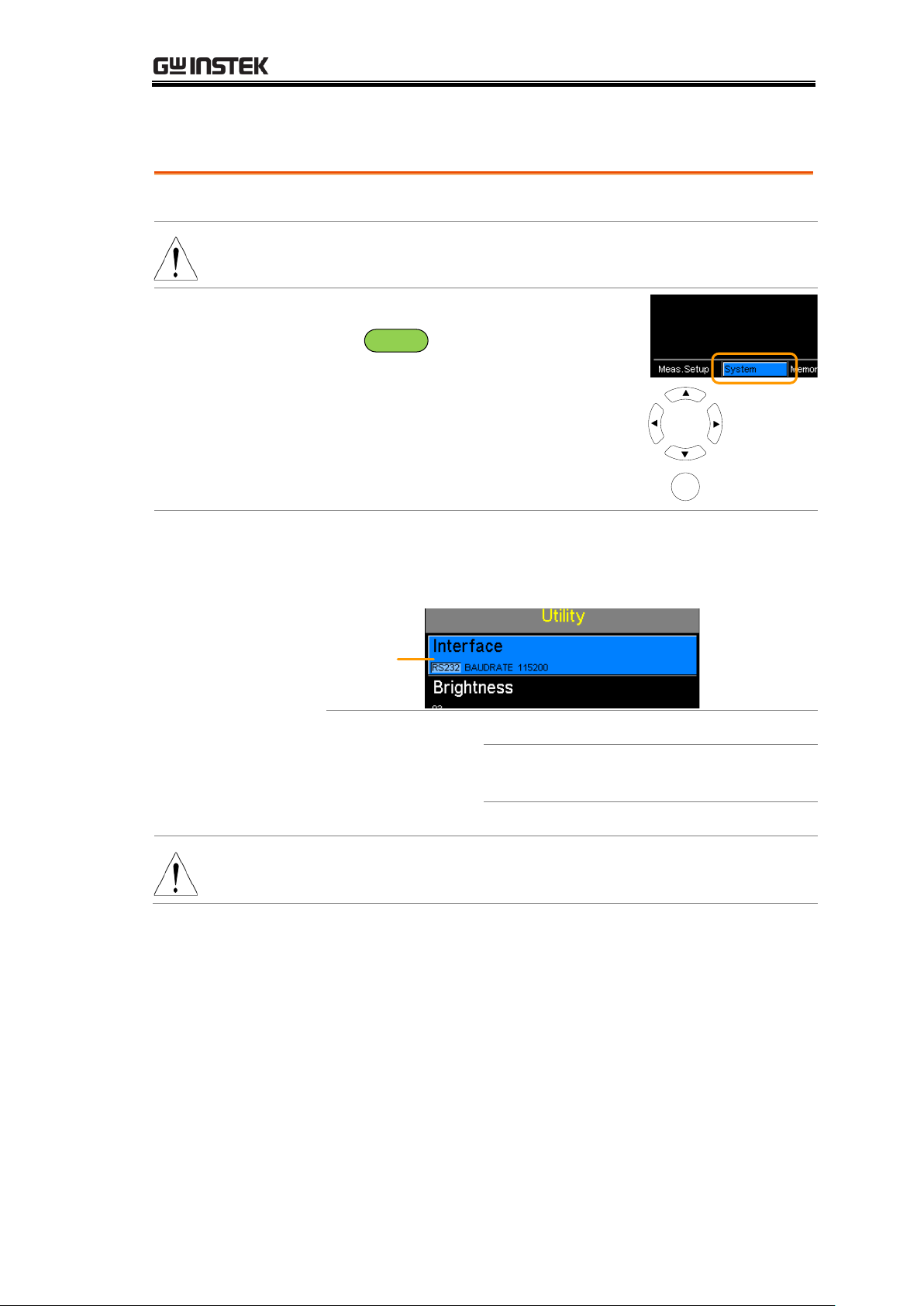
Interface
Background
The remote interface can be set to RS232, GPIB or USB.
Note
The GPIB interface is only available on the GOM-804G
and the GOM-805.
1. Select
Interface setting
From one of the main screens, press
the
ESC
key so that the menu
system at the bottom of the display
has focus.
Go to System and press Enter.
Go to Utility and press Enter.
Go to Interface and press Enter.
System
menu icon
Move
Select menu
or setting
Enter
2. Interface
setting appears
Use the arrow keys to choose an interface and to set the
baud rate (RS232) or primary address (GPIB). Press
Enter to confirm the setting.
Interface
GPIB, Primary Address (1 ~ 30)
RS232, Baud Rate (1200, 2400, 4800,
9600, 19200, 38400, 57600, 115200)
USB
Note
Pressing ESC before pressing ENTER will exit from the
Interface settings.
MEASUREMENT
71
Page 72
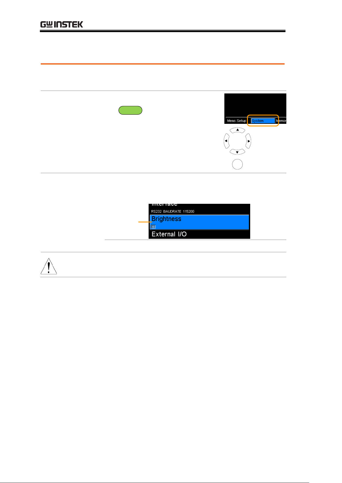
Brightness
Background
The Brightness setting sets the backlight brightness of
the TFT-LCD panel.
1. Select
Brightness
setting
From one of the main screens, press
the
ESC
key so that the menu
system at the bottom of the display
has focus.
Go to System and press Enter.
Go to Utility and press Enter.
Go to Brightness and press Enter.
System
menu icon
Move
Select menu
or setting
Enter
2. Brightness
setting appears
Use the arrow keys to set the brightness level. Press
Enter to confirm the setting.
Brightness
Brightness
01 (dim) ~ 05 (bright)
Note
Pressing ESC before pressing ENTER will exit from the
Brightness settings.
GOM-804 & GOM-805 User Manual
72
Page 73
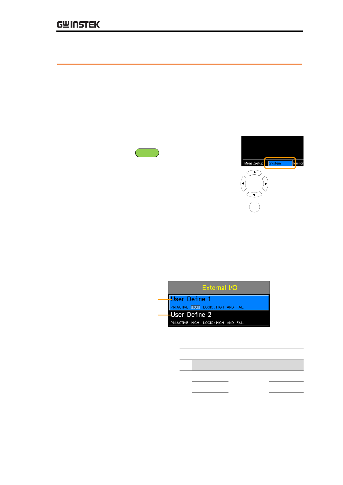
User Define Pins
Background
The External I/O User Define Pin settings set the logic
and the active level for the Define 1 and Define 2 pins on
the Handler/Scan/EXT I/O port on the rear panel. The
External I/O pins are used with the compare or bin
functions. The logic settings can be based on the pass,
fail, high, low or bin grade results of the selected
function.
1. Select External
I/O Setting
From one of the main screens, press
the
ESC
key so that the menu
system at the bottom of the display
has focus.
Go to System and press Enter.
Go to Utility and press Enter.
Go to External I/O and press
Enter.
System
menu icon
Move
Select menu
or setting
Enter
2. External I/O
Menu Appears
Use the arrow keys to choose either User Define 1 or
User Define 2 and press Enter.
Use the arrow keys to set the active level of the pin when
the logic conditions are true and to set the logic settings.
Press Enter to confirm the settings.
User Define 1
User Define 2
User Define 1/2:
Pin Active:
High, Low
Logic:
Operand1
Operator
Operand2
Fail
Logical OR,
Logical
AND,
OFF*
Fail
Pass
Pass
Low
Low
High
High
Bin O**
Bin O**
Bin 1 ~ 8
Bin 1 ~ 8
MEASUREMENT
73
Page 74
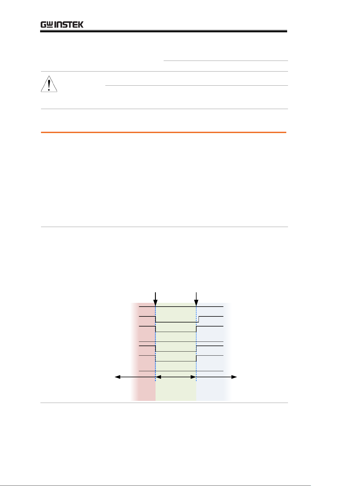
*The OFF operator sets the Logic as
true when Operand1 is true.
** Bin O is defined as outside bin 1~ 8.
Note
The Bin logic settings are not available for the GOM-804.
Pressing ESC before pressing ENTER will exit from the
selected External I/O setting.
Handler Mode
Background
The Handler Mode setting determines the behavior of
the result signals from the handler interface. There are
two settings, Clear and Hold. The Clear setting will clear
the results of the previous test before starting the
succeeding one and the Hold setting will keep the test
result of the previous test until the succeeding test has
completed.
The timing diagrams below are used as examples. All the
result signals in the examples are active high.
Clear example
Clear: All result signals (PASS, Fail, High and Low) are
cleared at the falling edge of EOT and the results from
the current test are output at the rising edge of the EOT
signal.
Previous
results
cleared
New
results
Trigger
Ready
EOT
Pass
Fail
High
Low
EOT falling
edge
EOT rising
edge
Previous
results
GOM-804 & GOM-805 User Manual
74
Page 75
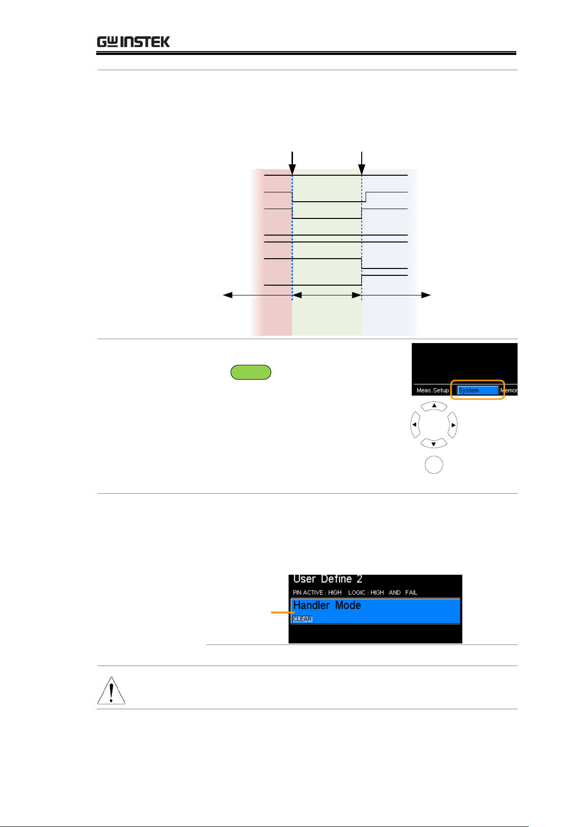
MEASUREMENT
Hold example
Hold: The results of the previous tests are held until the
current test has completed.
Previous results
held
New results
Trigger
Ready
EOT
Pass
Fail
High
Low
EOT falling
edge
EOT rising
edge
Previous
results
1. Select External
I/O setting
From one of the main screens, press
the
ESC
key so that the menu
system at the bottom of the display
has focus.
Go to System and press Enter.
Go to Utility and press Enter.
Go to External I/O and press
Enter.
System
menu icon
Move
Select menu
or setting
Enter
2. External I/O
menu appears
Use the arrow keys to choose Handler Mode and press
Enter.
Use the arrow keys to set the handler mode. Press Enter
to confirm the setting.
Handler Mode
Handler Mode
HOLD, CLEAR
Note
Pressing ESC before pressing ENTER will exit from the
Handler Mode setting.
75
Page 76
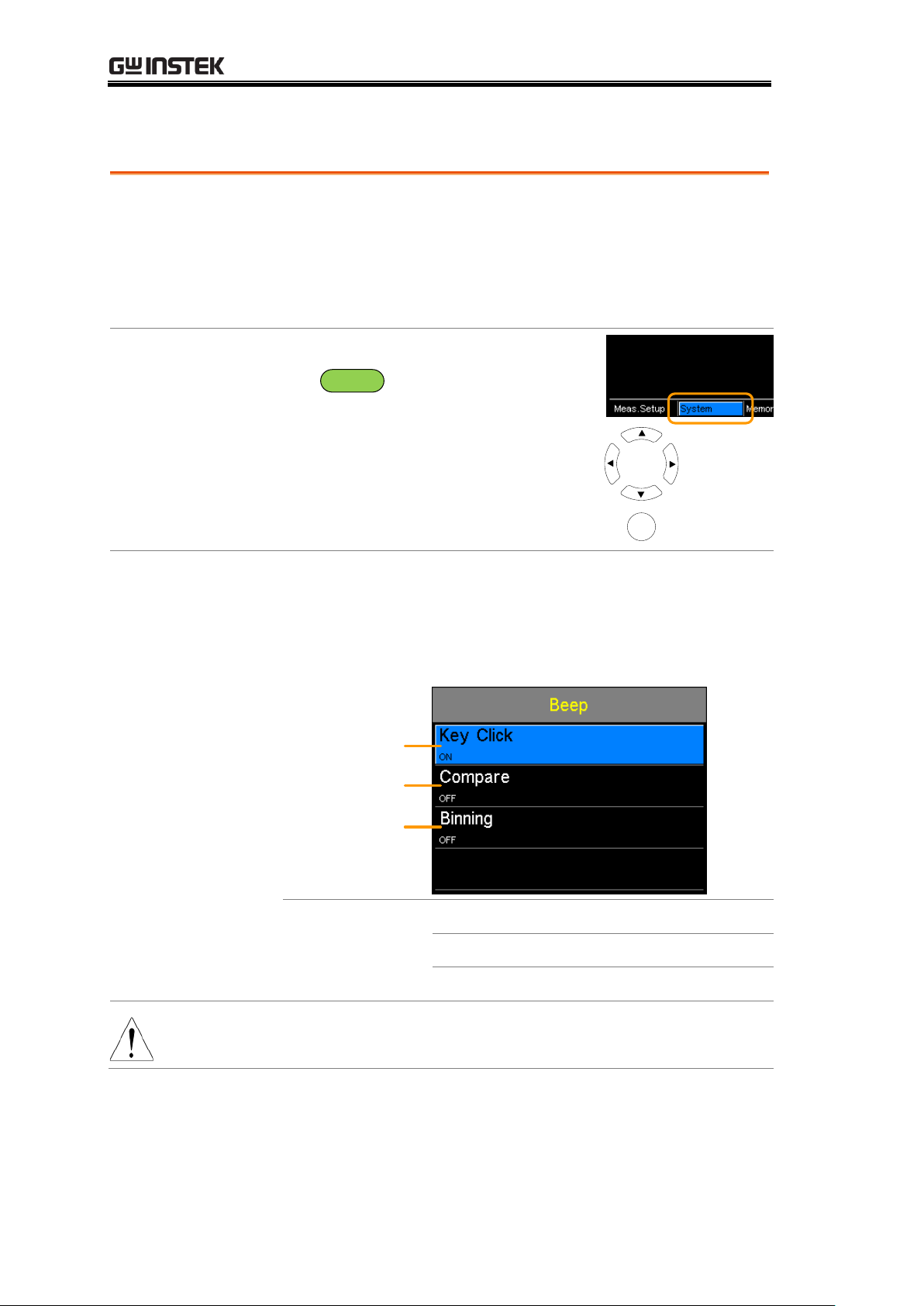
Beep
Background
The Beep setting will configure the beeper sound for the
key presses, the Compare function and the Binning
function.
For the Compare and Binning function the beep can be
configured to beep on a pass or fail judgment.
1. Select Beep
setting
From one of the main screens, press
the
ESC
key so that the menu
system at the bottom of the display
has focus.
Go to System and press Enter.
Go to Utility and press Enter.
Go to Beep and press Enter.
System
menu icon
Move
Select menu
or setting
Enter
2. Beep menu
appears
Use the arrow keys to choose a beep setting and press
Enter.
Use the arrow keys to set the selected setting and press
Enter to confirm.
Key Click Setting
Compare Setting
Binning Setting
Beep Settings:
Key Click
On, Off
Compare
Off. Pass, Fail
Binning
Off. Pass, Fail
Note
Pressing ESC before pressing ENTER will exit from the
selected Beep setting.
GOM-804 & GOM-805 User Manual
76
Page 77
HANDLER/SCAN INTERFACE
Handler
Handler Overview ................................................... 78
Pin Definitions for the Handler Interface ............... 80
Handler Interface for Binning and Compare
Functions ............................................................... 80
Scan
Scan Overview ........................................................ 82
Pin Definitions for the SCAN Interface ................... 83
Scan Interface ........................................................ 83
Scan Setup ............................................................. 84
Scan Output ........................................................... 88
GOM-802
Compatibility
GOM-802 Compatibility for Scan and Handler
Interfaces ............................................................... 89
GOM-805 to GOM-802 Handler/Scan Interface ..... 89
Remote Interface
Configure USB Interface ......................................... 90
Install USB Driver .................................................. 91
Configure RS-232 Interface ..................................... 92
Configure GPIB Interface ....................................... 93
RS232/USB Function Check ................................... 93
Using Realterm to Establish a Remote Connection
............................................................................... 94
GPIB Function ........................................................ 96
HANDLER/SCAN
INTERFACE
77
Page 78
Handler Overview
Background
The Handler interface is used to help grade components
based on the Compare or Binning function test results.
The appropriate pins on the handler interface are active
when the Compare or Binning function is used.
There are 17 TTL outputs and 1 TTL inputs. The
Handler interface is only applicable with the Binning
function or Compare measurement modes.
Note
Please see following pages for related functions and
settings:
Compare function: 41
Binning function: 46
Ext I/O settings: 73
Handler mode settings 74
Interface and pin
assignment
25-Pin D-SUB
(Female)
HANDLER / SCAN / EXT I/O
Pin assignment
TRIGGER
Starts the trigger for a single
measurement.
READY
High when the measurement has
finished. The instrument is ready for
the next trigger.
EOT
High when the AD conversion has
completed. The DUT is ready to be
changed.
BIN 1~8
High when the sorting result is in one
of the eight bin grades. Bin1~8 (pass).
BIN OUT
High when the sorting result is out of
all the eight bin grades (Bin1~8). The
status of this pin reflects either a HI or
LO result (fail).
LOW
High when the compare result is
deemed LO.
HIGH
High when the compare result is
deemed HI.
GOM-804 & GOM-805 User Manual
78
Page 79
HANDLER/SCAN INTERFACE
FAIL
High when the compare result is either
HI or LO (fail).
PASS
High when the compare result is IN
(pass).
For the full pin definition, please refer to the table listed below.
Note
The output current from all the pins and the VINT(+5V)
pin cannot exceed 60mA.
79
Page 80
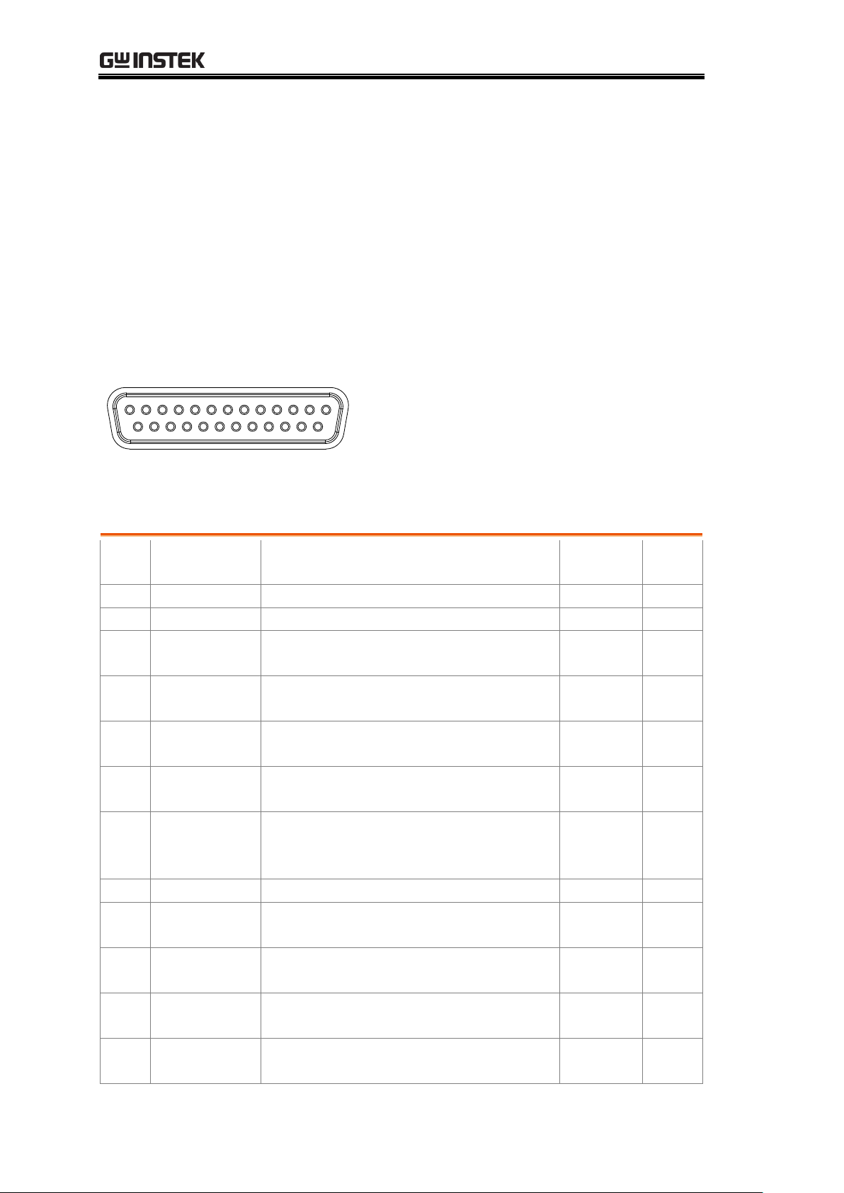
GOM-804 & GOM-805 User Manual
HANDLER / SCAN / EXT I/O
1
14
13
25
Pin
Name
Description
Active
modes
In/
Out
1, 17
Reserved
2
Trigger
Trigger for a single measurement.
All
In
3, 14,
18
GND
Ground.
4
Fail
High when the compare result is
either HI or LO (fail).
Compare
Out
5
High
High when the compare result is
deemed HI.
Compare
Out
6
Pass
High when the compare result is IN
(pass).
Compare
Out
7
EOT
High when the AD conversion has
completed. The DUT is ready to be
changed.
Ext
trigger
mode
Out
8
VINT
Internal DC Voltage +5V.
Out
9
Bin1
High when the binning sorting result
is within the bin1 setting range.
Binning
Out
10
Bin2
High when the binning sorting result
is within the bin2 setting range.
Binning
Out
11
Bin3
High when the binning sorting result
is within the bin3 setting range.
Binning
Out
12
Bin4
High when the binning sorting result
is within the bin4 setting range.
Binning
Out
Pin Definitions for the Handler
Interface
As this interface is used for the handler and scan functions, the interface
pinout depends on the function mode. The following pinout is only applicable
when using the Binning or Compare function.
Handler Interface for Binning and Compare Functions
80
Page 81
HANDLER/SCAN INTERFACE
13
Bin5
High when the binning sorting result
is within the bin5 setting range.
Binning
Out
15
Userdefine2
High or low when the user define2
logic conditions are met.
Compare,
Binning
Out
16
Userdefine1
High or low when the user define1
logic conditions are met.
Compare,
Binning
Out
19
VEXT
External DC Voltage, acceptable
range is +5V.
In
20
Ready
High when the measurement has
finished. The instrument is ready for
the next trigger.
Ext
trigger
mode
Out
21
Bin6
High when the binning sorting result
is within the bin6 setting range.
Binning
Out
22
Low
High when the compare result is
deemed LO.
Compare
Out
23
Bin7
High when the binning sorting result
is within the bin7 setting range.
Binning
Out
24
Bin8
High when the binning sorting result
is within the bin8 setting range.
Binning
Out
25
Bin Out
High when the binning sorting result
is out of all the bin setting ranges.
Binning
Out
For backwards compatibility with the GOM-802 handler interface, please see
page 89.
81
Page 82
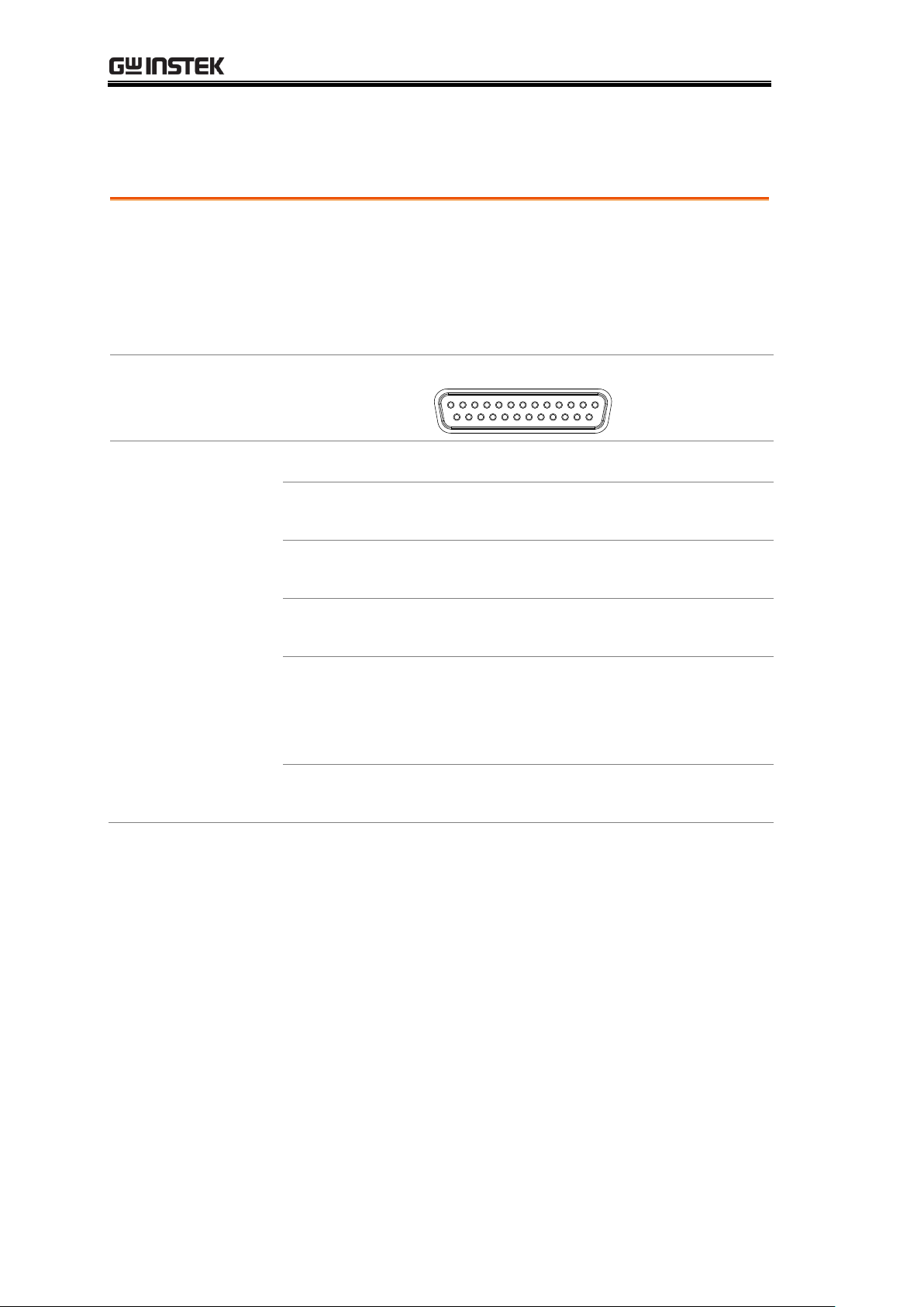
Scan Overview
Background
The Scan function is used to automatically bin groups of
up to 100 components. The associated pins in the handler
interface are active when the Scan function is activated.
There are a total of 6 outputs, 3 inputs as well as a GND
and power (+5V) pin.
Interface and pin
assignment
25Pin D-SHELL
(Female)
HANDLER / SCAN / EXT I/O
Pin Assignment
Relay
Controls the relay output.
Pass
Pass signal. Indicates the compare result
is IN(pass).
Low
Low signal. Indicates a LO compare
result.
High
High signal. Indicates a HI compare
result.
Clock
The clock signal will pulse high when
each group of output signals (Relay,
Pass, Low, High) are ready. There are up
to 100 groups of output signals
STRB
After all (100) output groups are ready,
the STRB signal will pulse high.
GOM-804 & GOM-805 User Manual
82
Page 83
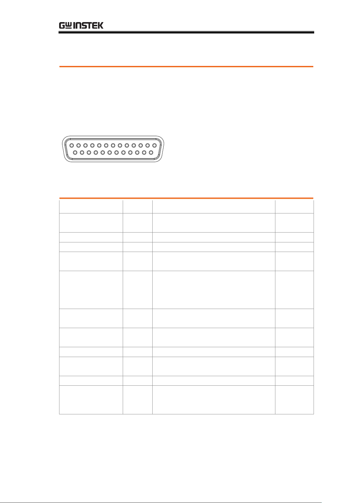
HANDLER/SCAN INTERFACE
HANDLER / SCAN / EXT I/O
1
14
13
25
Pin
Name
Description
In/Out
1,9-13,15-17,21,23
-25
Reserved
2
Trigger
Start for Scan measurement.
In
3,14,18
GND
Ground.
4
High
High signal. Indicates a HI compare
result.
Out
5
Clock
The clock signal will pulse high when
each group of output signals (Relay,
Pass, Low, High) are ready. There are
up to 100 groups of output signals.
Out
6
Low
Low signal. Indicates a LO compare
result.
Out
7
Pass
Pass signal. Indicates an IN compare
result (pass).
Out
8
VINT
Internal DC Voltage +5V.
Out
19
VEXT
External DC Voltage, acceptable
range is +5V.
In
20
Relay
Controls the relay output.
Out
22
STRB
After all (up to 100) output groups
are ready, the STRB signal will pulse
high.
Out
Pin Definitions for the SCAN Interface
As this interface is used for the handler and scan functions, the interface
pinout depends on the function mode. The following pinout is only applicable
when using the Scan function.
Scan Interface
For backwards compatibility with the GOM-802 scanner interface, please see
page 89.
83
Page 84
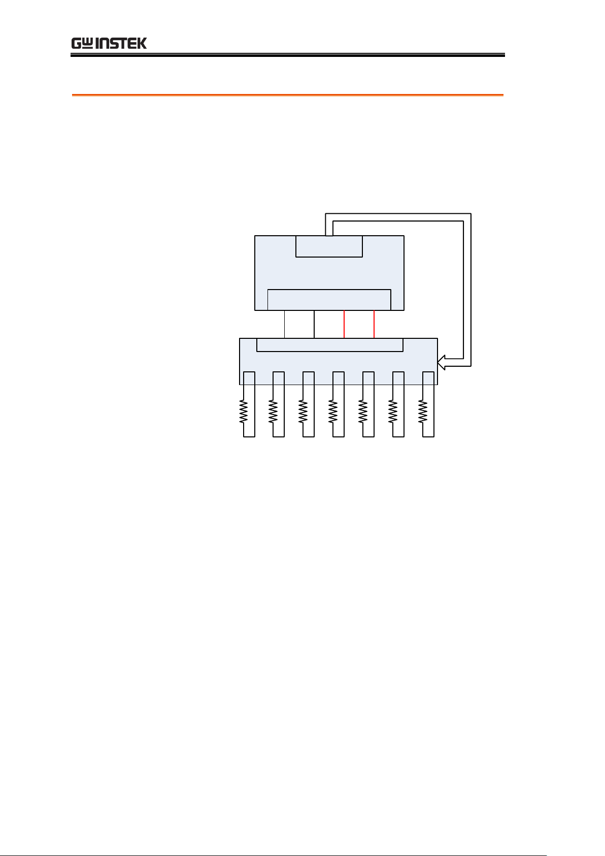
GOM-804 & GOM-805 User Manual
Background
The Scan function sequentially scans up to 100 channels
and grades the resistance of the DUT on each channel to
a reference value. An automated handler or test fixture is
required to interface the DUTs to the measurement
terminals and the scan interface that controls the timing
of each scan.
GOM-805
Scan I/O
Measurement terminals
Automated Handler/Test Fixture
1 2 3 4 5 6 NChannel
DUT 1~N
S+ Source+Source- S-
·····
Note: The automated handler/test fixture is
user-supplied. Please see your distributor for support and
technical details.
Grading of each DUT is essentially the same as the
compare function (page 41), the difference being the
Scan function will compare up to 100 DUTs sequentially,
whereas the Compare function will compare only one
DUT at a time.
The scan function compares a measured value to a
“Reference” value that has an upper (HI) and lower (LO)
limit. If the measured value is within the upper and lower
limit, then the measured value is judged as IN.
There are two modes that can be used to make a
judgment: ABS and △% modes.
The ABS mode compares the measured value to the
upper (HI) and lower (LO) limits. The upper and lower
limits are set as absolute resistance values.
The △% compare function compares the deviation of
Scan Setup
84
Page 85
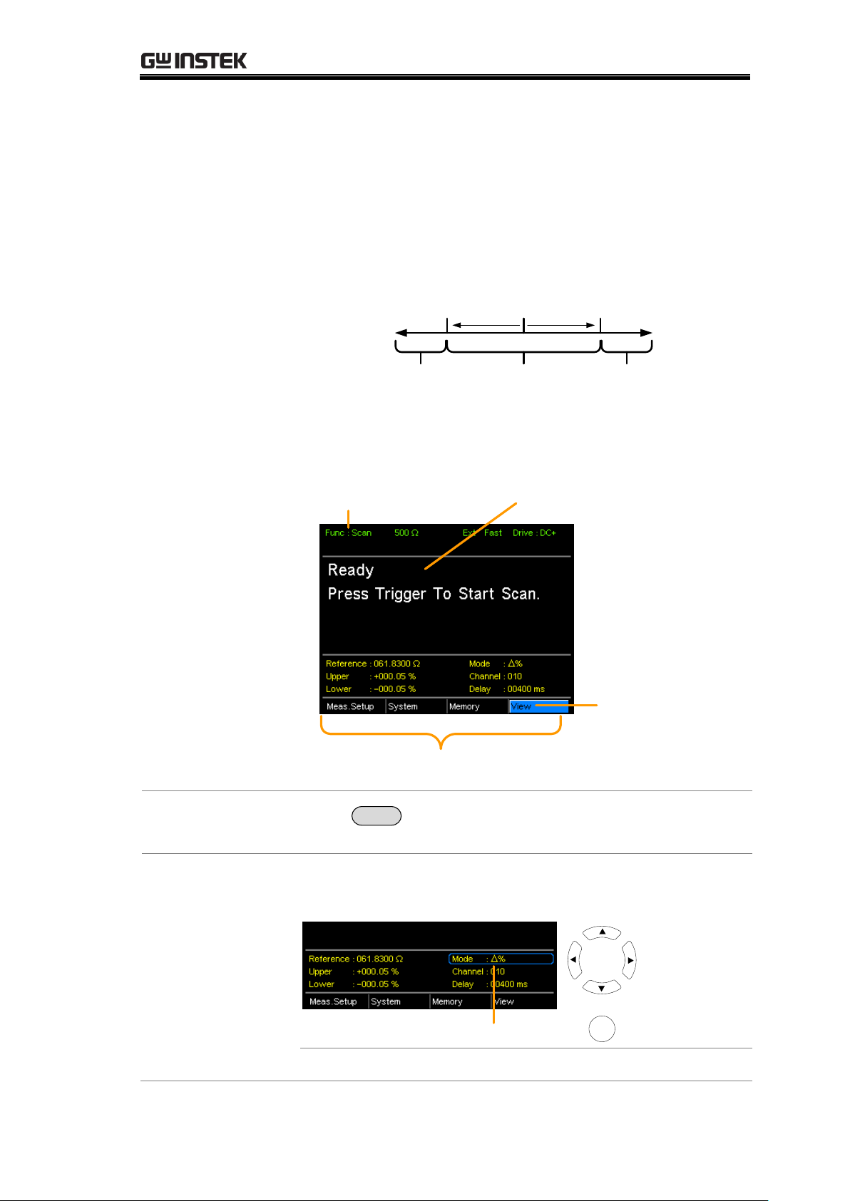
HANDLER/SCAN INTERFACE
the measured value from the reference value as a
percentage.
{ [(Measured Value-Reference)/Reference]%}.
A measured value that falls within the upper and lower
limits is considered IN (pass), a value that falls below the
lower limits is considered LO, and a value that falls over
the upper limit is a HI.
Reference
value
Upper
limit
Lower
limit
IN HILO
For both scan modes, the IN, HI or LO will be shown on
the display for each judgment (if the time between each
judgment is not too fast).
Display Overview
Scan function
indicator
Ready to start scan message
Reference, limits, scan mode, current
channel, measurement delay
Change
display view
1. Select the
Scan function
Press
Scan
Scan to access the scan mode, as shown
above.
2. Select the
compare mode
Use the arrow keys to navigate to the Mode setting. Press
the Enter key to toggle the compare mode.
Mode
Move
Toggle
Enter
Range
Abs, △ %
85
Page 86
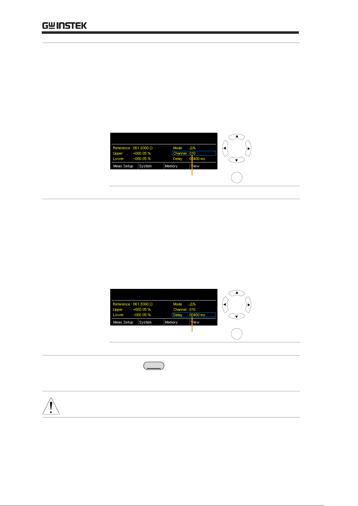
GOM-804 & GOM-805 User Manual
3. Channel
setting
The Channel setting sets the number of DUT channels
that are used.
Use the arrow keys to navigate to the Channel setting and
press Enter.
Use the left and right arrow keys to select a digit. Use the
up and down arrow keys to edit the value of the selected
digit. Press Enter to confirm the setting.
Channel setting
Move
and edit
Select and
confirm
Enter
Channel Range:
01 ~100
4. Delay setting
The Delay setting adds a pause between each channel
measurement.
The Use the arrow keys to navigate to the Delay setting
and press Enter.
Use the left and right arrow keys to select a digit. Use the
up and down arrow keys to edit the value of the selected
digit. Press Enter to confirm the setting.
Delay setting
Move
and edit
Select and
confirm
Enter
Delay Range:
400ms ~ 30000ms
5. Start the scan.
Press the
Trigger
key or input a pulse signal on the
Trigger pin of the SCAN interface port to start a scan
test.
Note
See page 64 to set the external trigger edge as a rising or
falling leading edge.
The results will be displayed on the screen as each test is
performed. The results will also be output through the
scan port until the scan has finished.
86
Page 87
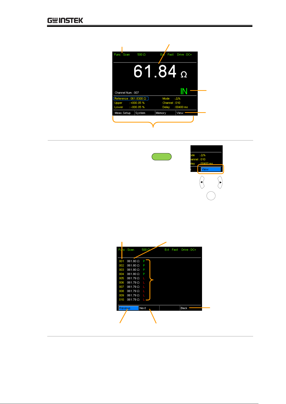
HANDLER/SCAN INTERFACE
Scan function
indicator
Pass/Fail
judgment
Measured value
Reference, limits, scan mode, current
channel, measurement delay
Change
display view
6. View Results
After the last SCAN test has
finished, press the
ESC
key
so that the menu system at the
bottom of the display has focus.
Go to View and press Enter to
view the results of each channel.
View display
results
Move
Select
Enter
Use the Previous and Next soft-keys to view each page.
Use the Back soft-key to return to the previous window.
Channel number
Pass/High/Low
(P/H/L)
judgment results
Previous
results page
Return to
the
previous
window
Measurement
results
Next results
page
87
Page 88
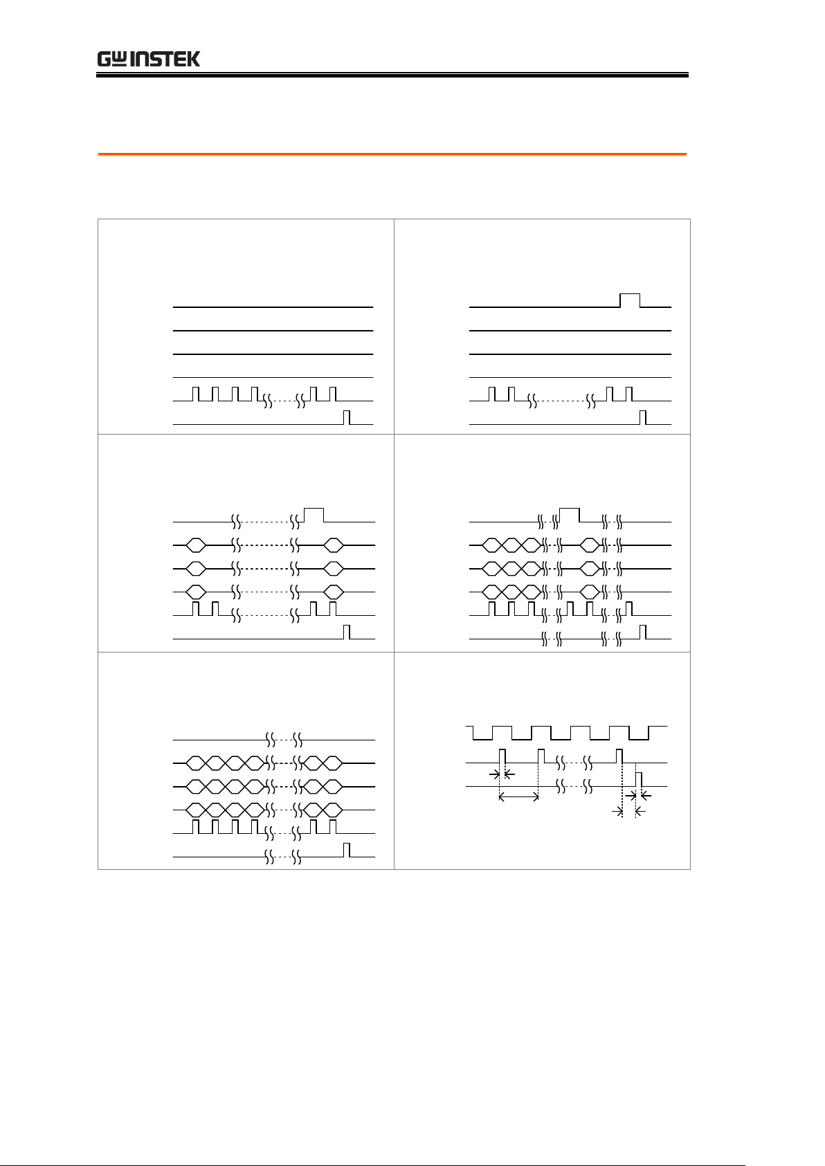
Scan Output
Background
The timing diagrams for the scan output under different
conditions are shown below.
Ready message displayed…
After the manual trigger key is
pressed….
Relay
Pass
Low
High
Clock
STRB
100 99 98 97 2 1
Relay
Pass
Low
High
Clock
STRB
100 99 2 1
Scan channel 1. Delay time has
elapsed.
Scan channel n. Delay time has
elapsed.
Relay
Pass
Low
High
Clock
STRB
100 99 2 1
Relay
Pass
Low
High
Clock
STRB
100 99 n+1 198
n
Scan Channel 100. Delay time has
elapsed.
Scan output signal timing.
Relay
Pass
Low
High
Clock
STRB
100 99 2 198 97
Data
Pass
STRB
20us
168us
38us
20us
GOM-804 & GOM-805 User Manual
88
Page 89
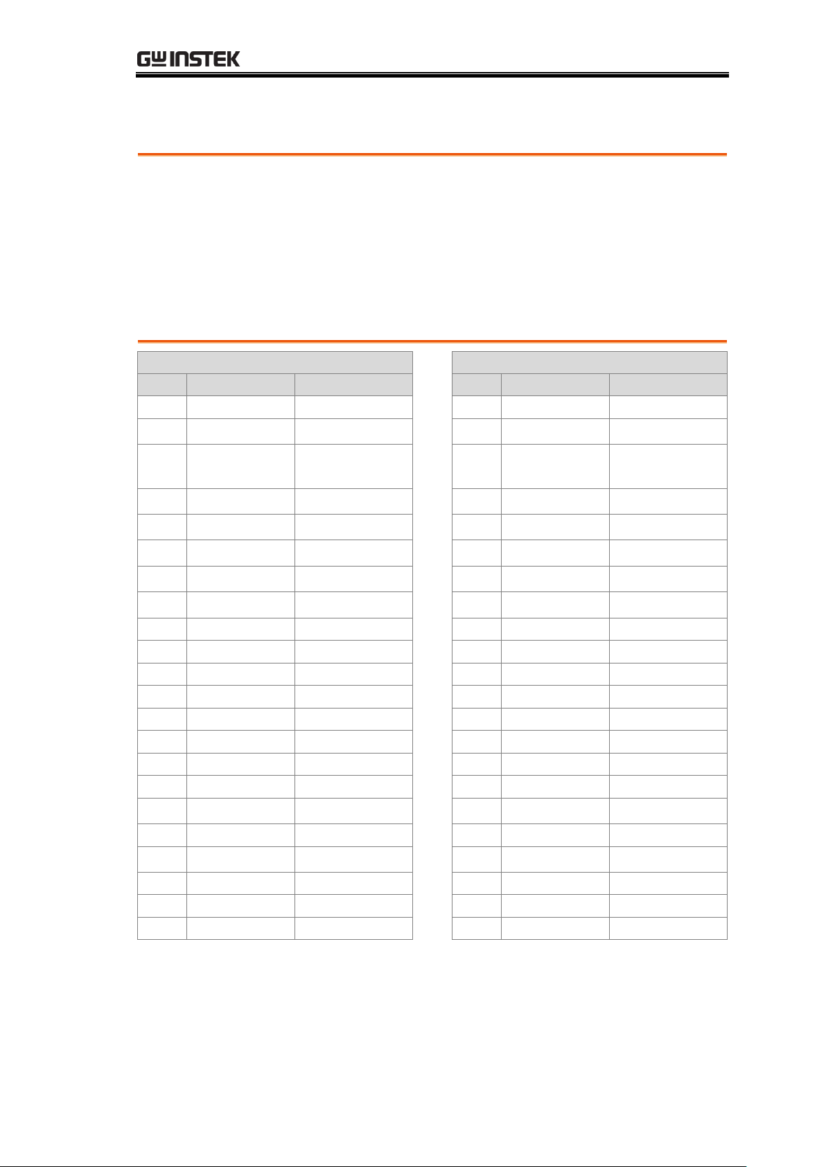
HANDLER/SCAN INTERFACE
GOM-805 Handler Interface
GOM-802 Handler Interface
Pin
Handler
Scan
Pin
Handler
Scan
1, 17
Reserved
Reserved
2
Trigger
Trigger
→
3
Start
NC
3, 14,
18
GND
GND
→
2
GND
GND
4
Fail
High
→
7
Fail
High
5
High
Clock
→
8
High
Clock
6
Pass
Low
→
6
Pass
Low
7
EOT
Pass
→
5
EOT
Pass
8
VINT
+5V
→
1
+5V
+5V
9
Bin1
10
Bin2
11
Bin3
12
Bin4
13
Bin5
15
Userdefine2
16
Userdefine1
19
VEXT
VEXT
20
Ready
Relay
→
4
Ready
Relay
21
Bin6
22
Low
STRB
→
9
Low
STRB
23
Bin7
24
Bin8
25
Bin Out
GOM-802 Compatibility for Scan and Handler Interfaces
As the handler interface on GOM-802 is a 9-pin D-sub and the GOM-805 is a
25-pin D-sub, the GOM-805 handler interface cannot be used with existing
GOM-802 ATE equipment or environments without modification.
For backwards compatibility with the GOM-802 handler interface, please refer
to the chart below:
GOM-805 to GOM-802 Handler/Scan Interface
89
Page 90
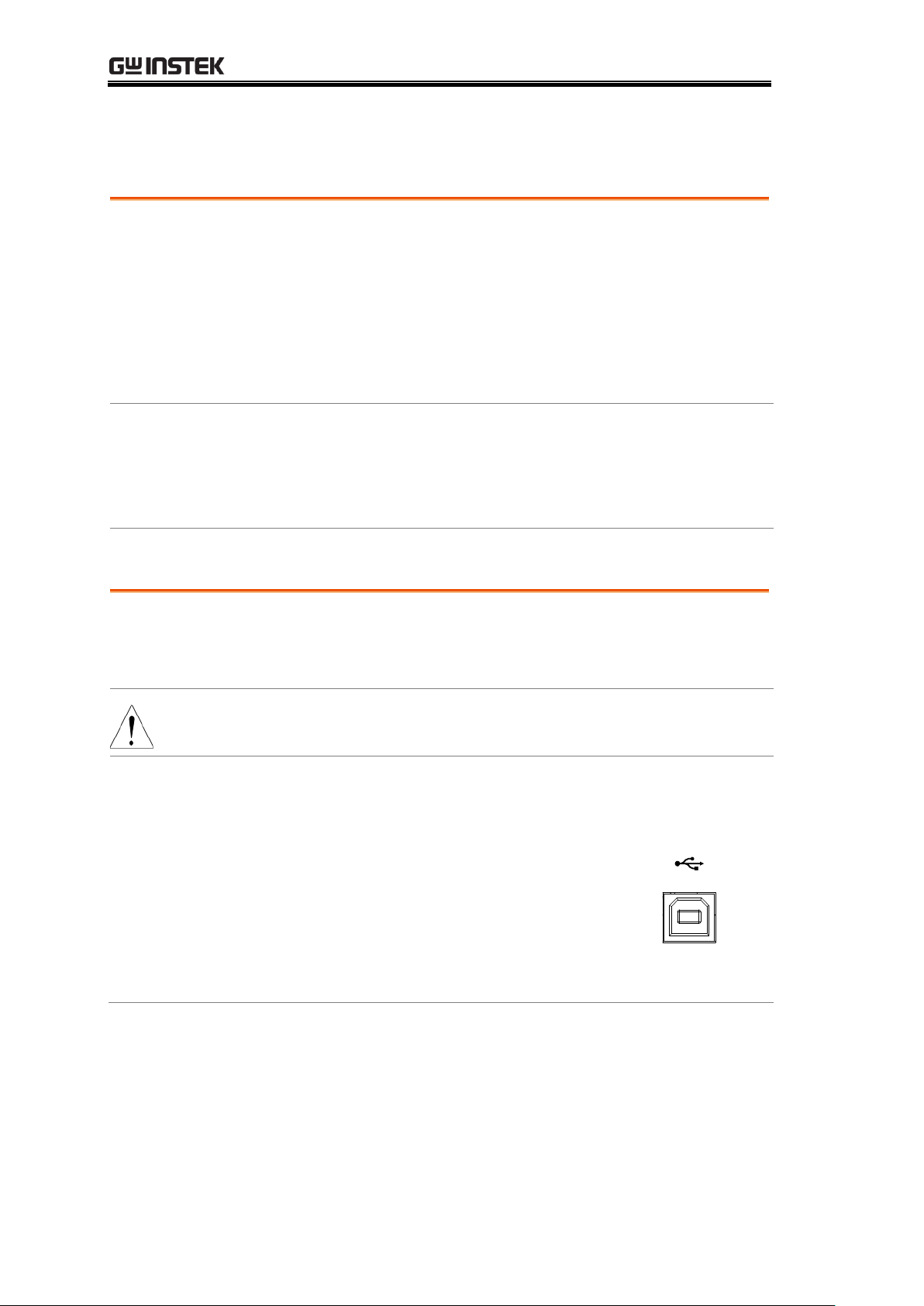
Configure Interface
Overview
The RS-232 and USB interfaces are standard for all
models, however the GPIB interface is only applicable
for the GOM-804G and GOM-805. The remote control
interfaces allow the GOM-804/805 to be programmed
for automatic testing.
For more information on remote control programming,
please see the Command Overview chapter on page 102.
Interface
USB
USB HOST
RS-232
DB-9 male port
GPIB
24 pin female GPIB port (GOM-804G,
GOM-805 only)
Background
The Type B USB port on the rear panel is used for
remote control. This interface creates a virtual COM port
when connected to a PC.
Note
The USB interface requires the USB driver to be
installed. See page 91 to install the USB driver.
1. Connect and
configure to
USB.
Configure the interface to USB in
System>Utility>Interface menu.
Page 71
Connect the Type A-B USB cable to the
rear panel USB B port on the
GOM-804/805.
Connect the other end to the Type A port
on the PC.
GOM-804 & GOM-805 User Manual
Configure USB Interface
90
Page 91
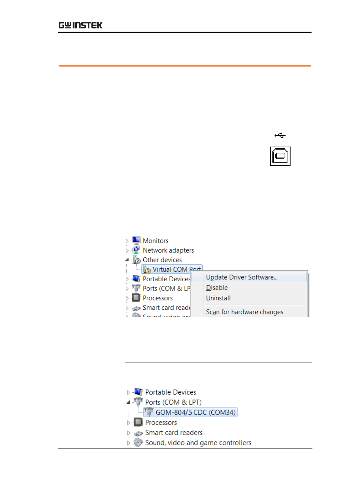
Install USB Driver
Background
The USB driver needs to be installed when using the USB
port for remote control. The USB interface creates a
virtual COM port when connected to a PC.
1. Select the USB
driver.
Configure the interface to USB in
System>Utility>Interface menu.
Page 71
Connect the Type A-B USB cable to the
rear panel USB B port on the
GOM-804/805. Connect the other end to
the Type A port on the PC.
Go to the Windows Device Manager.
For Windows 7 go to:
Start Menu > Control Panel > Hardware and Sound >
Device Manager
The GOM-804/805 will appear as an unknown Virtual
Com Port under “Other Devices”.
Right-click Other Devices and select “Update Driver
Software”.
Select “Browse my computer for driver software” and
select the driver on the User Manual CD.
The GOM-805 and the COM port that it is assigned to
will now appear in under the Ports (COM & LPT) node.
HANDLER/SCAN INTERFACE
91
Page 92
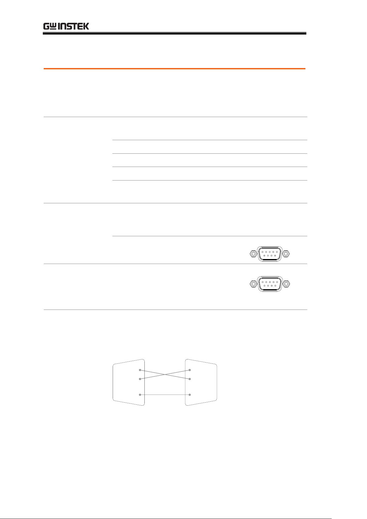
Configure RS-232 Interface
Background
The GOM-804/805 can also use an RS-232C connection
for remote control. When connecting to a PC ensure the
correct baud rate, parity, data bits, stop bit and data
control settings are used.
Settings
Baud rate
1200, 2400, 4800, 9600, 19200, 38400,
57600, 115200
Parity
None
Data bits
8
Stop bit
1
Data flow
control
None
1. Select the
RS-232 baud rate
Configure the interface to RS232 and
set the baud rate in
System>Utility>Interface menu.
Page 71
Connect the RS-232C cable to the rear
panel RS232 port.
RS232
RS-232 pin
assignment
Pin 2: RxD
Pin 3: TxD
Pin 5: GND
Pin 1, 4, 6 ~ 9: No Connection
195
6
PC – GOM
RS-232C
connection
The RS232C connection uses a Null-modem connection,
in which transmit (TxD) and receive (RxD) lines are
cross-linked.
GOM PC
TxD
RxD
GND
Pin2
Pin3
Pin5
TxD
RxD
GND
Pin2
Pin3
Pin5
GOM-804 & GOM-805 User Manual
92
Page 93
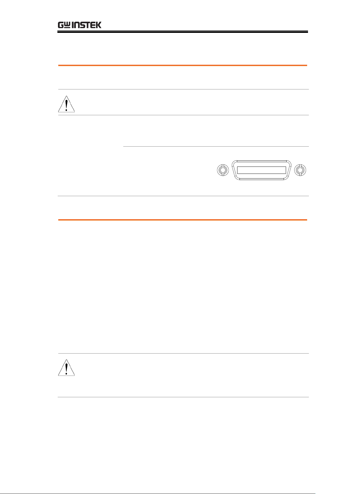
Configure GPIB Interface
Background
The GPIB interface is SCPI-1994, IEEE488.1 and
IEEE488.2 compliant.
Note
The GPIB interface is only available on the GOM-804G
and GOM-805.
1. Select the
GPIB address
Configure the interface to GPIB and set
the GPIB address in
System>Utility>Interface menu.
Page 71
Connect one end of the
GPIB cable to the computer
and the other end to the
GPIB port on the
GOM-805.
GPIB
Operation
Invoke a terminal application such as Realterm.
For RS-232, set the COM port, baud rate, stop bit, data
bit and parity accordingly.
To check the COM settings in Windows, see the Device
Manager. For example, in WinXP go to the Control panel
→ System → Hardware tab.
Run this query from the terminal.
*idn?
This should return the Manufacturer, Model number, and
Firmware version.
GWINSTEK,GOM805,GXXXXXXXX,V1.00
Note
If you are not familiar with using a terminal application
to send/receive remote commands from the serial port or
via a USB connection, please page 94 (Using Realterm to
Establish a Remote Connection) for more information.
HANDLER/SCAN INTERFACE
RS232/USB Function Check
93
Page 94
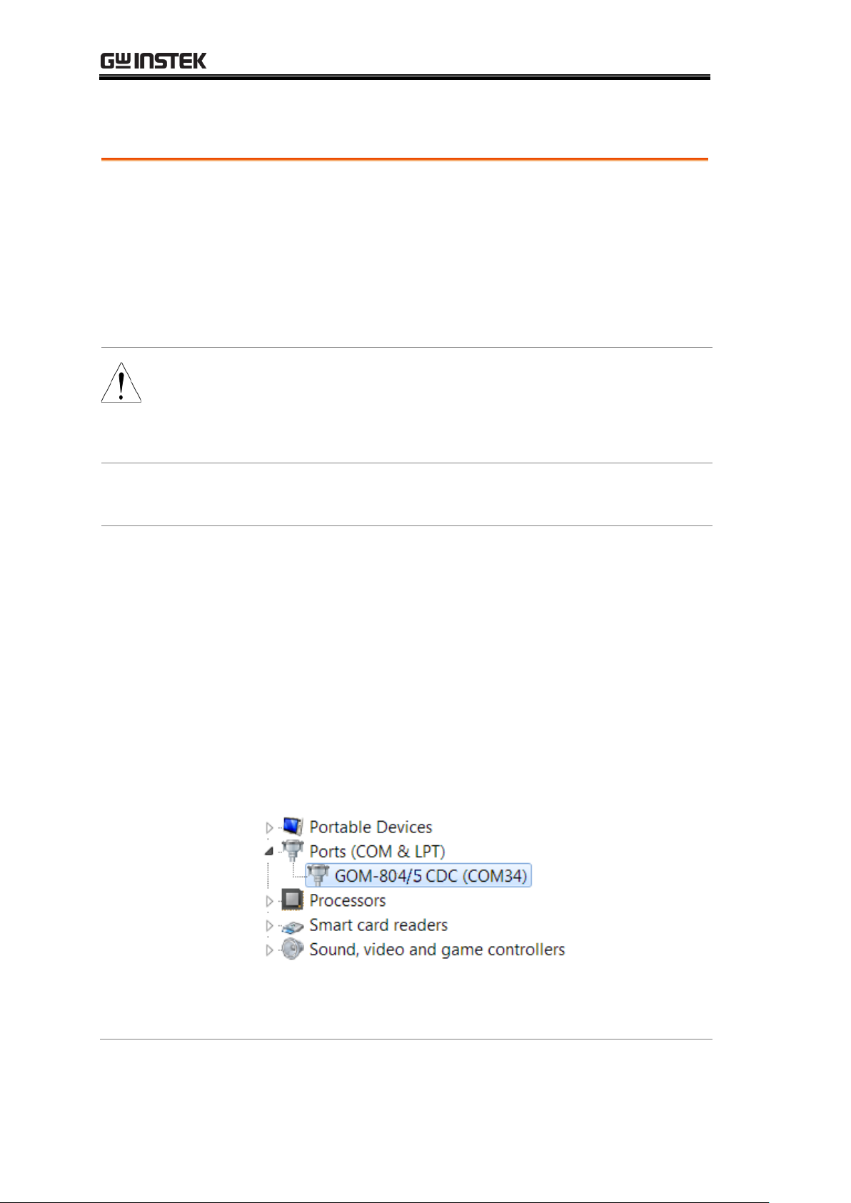
GOM-804 & GOM-805 User Manual
Background
Realterm is a terminal program that can be used to
communicate with a device attached to the serial port of
a PC or via an emulated serial port via USB.
The following instructions apply to version 2.0.0.70.
Even though Realterm is used as an example to establish
a remote connection, any terminal program can be used
that has similar functionality.
Note
Realterm can be downloaded on Sourceforge.net free of
charge.
For more information please see
http://realterm.sourceforge.net/
1. Install
Realterm
Download Realterm and install according to the
instructions on the Realterm website.
2. Configure
connection
Connect the GOM-804/805 via USB (page 90) or via
RS232 (page 92).
If using RS232, make note of the configured baud rate.
Go to the Windows device manager and find the COM
port number for the connection.
For example in Windows 7, go to the Start menu >
Control Panel > Hardware and Sound > Device Manager
Double click the Ports icon to reveal the connected serial
port devices and the COM port for each connected
device.
If using USB, the baud rate, stop bit and parity settings
can be viewed by right-clicking connected device and
selecting the Properties option.
Using Realterm to Establish a Remote Connection
94
Page 95
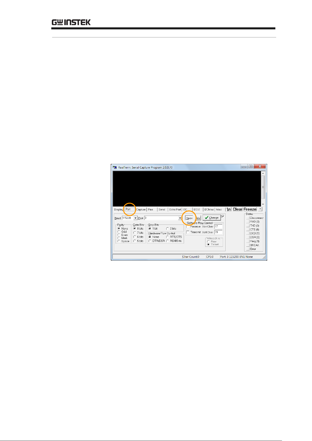
HANDLER/SCAN INTERFACE
2. Run Realterm
Start Realterm on the PC as an administrator.
Click:
Start menu>All Programs>RealTerm>realterm
Tip: to run as an administrator, you can right click the
Realterm icon in the Windows Start menu and select the
Run as Administrator option.
After Realterm has started, click on the Port tab.
Enter the Baud, Parity, Data bits, Stop bits and Port
number configuration for the connection.
The Hardware Flow Control and Software Flow Control
options can be left at the default settings.
Press Open to connect to the GOM-804/805.
95
Page 96
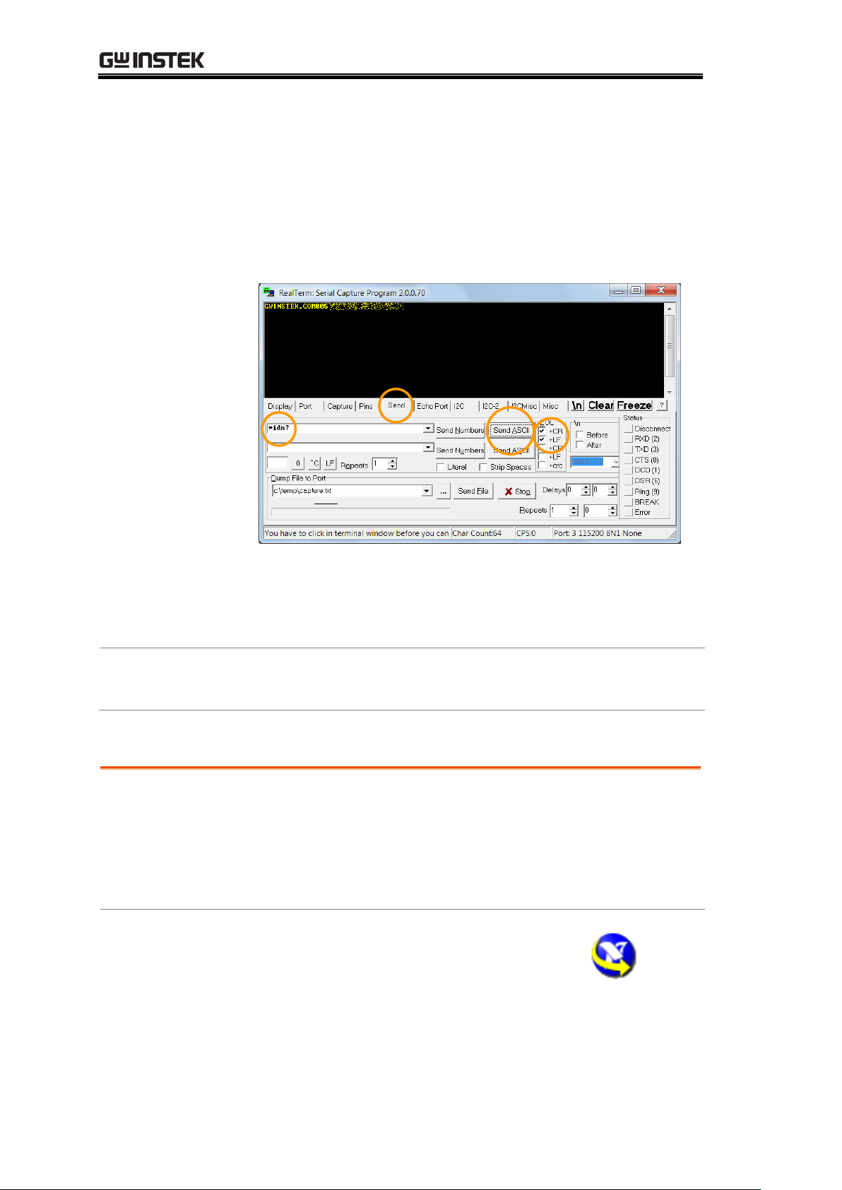
GOM-804 & GOM-805 User Manual
3. Test remote
command
Click on the Send tab.
In the EOL configuration, check on the +CR and +LF
check boxes.
Enter the query:
*idn?
Click on Send ASCII.
The terminal display will return the following:
GWINSTEK,GOM805,GXXXXXXXX,V1.00
(manufacturer, model, serial number, version)
4. Errors or
Problems
If Realterm fails to connect to the GOM-804/805, please
check all the cables and settings and try again.
Background
Please use the National Instruments Measurement &
Automation Controller software to confirm GPIB/LAN
functionality.
See the National Instrument website, http://www.ni.com
for details.
1. Operation
Start the NI Measurement and
Automation Explorer (MAX) program.
Using Windows, press:
GPIB Function
96
Page 97
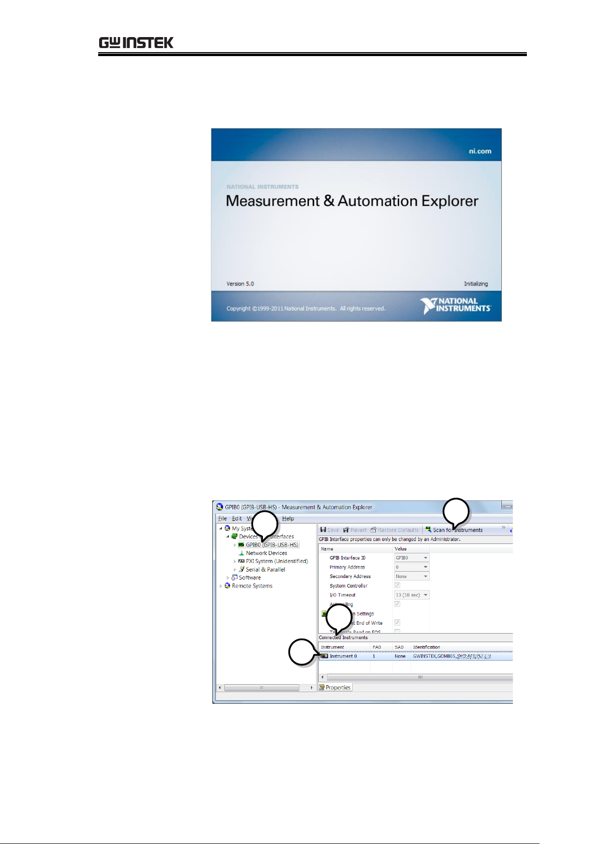
HANDLER/SCAN INTERFACE
Start>All Programs>National
Instruments>Measurement & Automation
Step a.
From the Configuration panel access;
My System>Devices and Interfaces>GPIB0
Step b.
Press the Scan for Instruments button.
Step c.
In the Connected Instruments panel the GOM-804/805
should be detected as Instrument 0 with the address the
same as that configured on the unit.
Step d.
Double click the Instrument 0 icon.
a
b
c
d
Step e.
Click on the Attributes tab at the bottom.
Step f.
Click on Communicate with Instrument.
97
Page 98
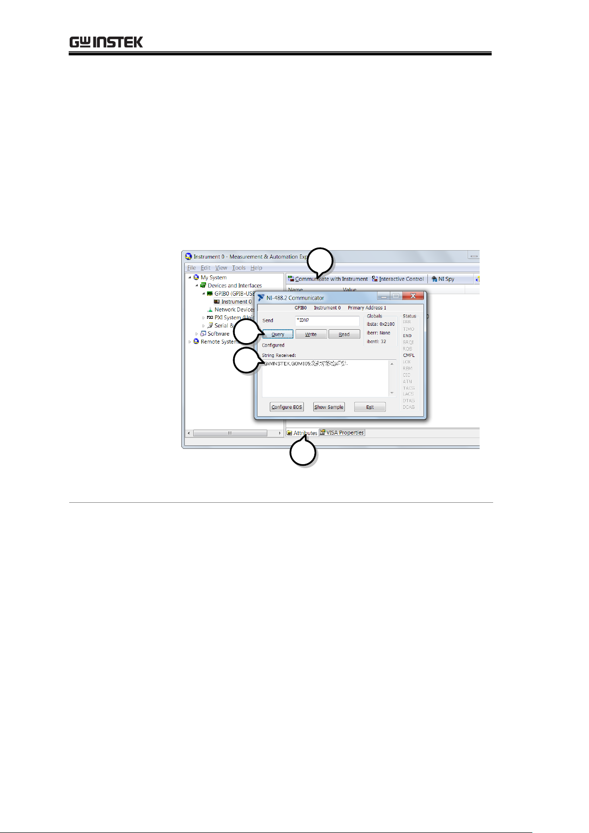
GOM-804 & GOM-805 User Manual
Step g.
In the NI-488.2 Communicator window, ensure *IND? is
written in the Send String: text box.
Click on the Query button to send the *IDN? query to
the instrument.
Step h.
The String Received text box will display the query
return:
GWINSTEK,GOM805,GXXXXXXXX,V1.00
(manufacturer, model, serial number, version)
f
g
h
e
The function check is complete.
98
Page 99
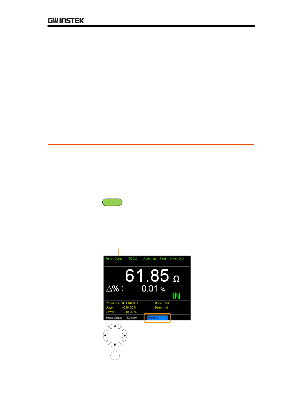
SAVE/RECALL
Background
The save function saves the current function as well the
settings related to that function.
There are 20 memory slots that can be used to save and
recall settings on the GOM-804/805.
1. Enter the
Memory menu
When you are in the desired function mode, press the
ESC
key (if necessary) to so that the menu system at
the bottom of the display has focus.
Use the arrow keys to navigate to the Memory setting
and press Enter.
Move
Select menu
or setting
Enter
Memory setting
Function mode
SAVE/RECALL
The settings for all the major functions can be saved and recalled from 20
memory slots.
Settings can saved/recalled for the following functions:
Ohm, Compare, Binning, TC, TCONV, TEMP, Scan, Diode.
Save/Recall Settings
99
Page 100
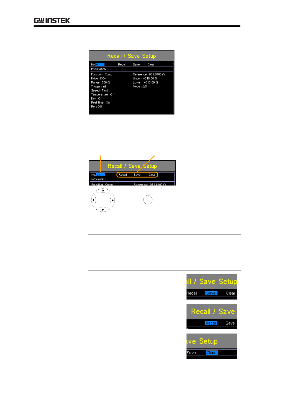
GOM-804 & GOM-805 User Manual
The Recall/Save Setup menu will appear.
2. Save/
Recall/Clear
Memory
The No. setting should be already highlighted when
entering the Recall/Save Setup menu. If not, use the
Left/Right arrow keys to highlight the No. setting.
No. setting
Recall, Save, Clear settings
Move
and edit
Select and
confirm
Enter
Use the up and down arrow keys to select a memory
space.
Range
01~20
*If a memory space has been used before , the
settings for that memory slot will also be shown
on the display.
To Save:
Use the arrow keys to go to Save
and press Enter.
To Recall:
Use the arrow keys to go to Recall
and press Enter.
To Clear:
Use the arrow keys to go to Clear
and press Enter.
100
 Loading...