

Page 1
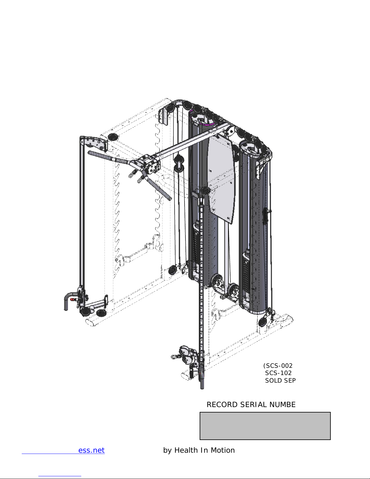
SCS-202
INSPIRE
SMITH CAGE SYSTEM OPTION-2
ASSEMBLY AND OPERATION MANUAL
SCS-102 SMITH BAR
SOLD SEPARATELY)
RECORD SERIAL NUMBER HERE
(SCS-002 SMITH CAGE,
www.inspirefitness.net by Health In Motion 11-15-14
Page 2

CONGRATULATIONS… You’ve just taken the first step to a healthier and
stronger body. This Smith Cage System by Inspire Fitness offers the key to
unlocking your body’s potential. Regular strength training has been shown
to deliver a host of benefits includ ing: incr eased musc le tone, decreased
body fat, improved energy levels, a reductio n in stress, and improved
cardiac output. Once again, congratulations, you are on your way to
improving your self image, overall health, and quality of life.
BEFORE ASSEMBLING SMITH CAGE SYSTEM
CAUTION:
Two people are required t o assemble the Smith Cage System to
ensure that parts do not fall that could result in injury to the persons
assembling the gym.
IMPORTANT: Read this entire manual before attempting to build or u se
this equipment. This manual contains step by step instructions for proper
assembly.
Use the parts list included in this manual to verify that all parts are
accounted for before assembly. If any parts are missing, contact the retailer
of this Smith Cage System for replacement parts. Or, call Inspire Fitness
at 877-738-1729.
Make sure that adequate room has been cleared before attempting to build
your Smith Cage System. A rubber mat is recommended for use under
your Smith Cage System to protect wood flooring or carpeting from damage
during assembly and usage.
This Smith Cage System is intended for indoor use only. In addition,
garages and screened in porches are not recommended due to high
humidity or dust. Rust could form on certain parts, including gu ide rods, in
a humid environment resulting in impaired function.
Service of your Smith Cage System should only be performed by an
authorized Inspire Fitness retailer. Service performed by anyone else can
result in loss of warranty. If you need help finding an authorized retailer,
please contact us directly:
Inspire Fitness
4945 East Hunter Avenue
Anaheim, CA 92807
Ph: 877-738-1729
Fx: 714-738-1728
www.inspirefitness.net
Page 3

TABLE OF CONTENTS
Section Description……………………………………………………. Page
Important Safety Instructions………………………………………. 1
Tools Required………………………………………………………………… 1
Parts & Hardware List……………………………………………………. 2
Cable Chart ……………………………………………………………………. 3
Assembly Instructions……………………………………………………. 4
Cable Adjustment ………………………………………………………….. 26
Exploded View ……………………………………………………………….. 27
Decal Reference ………… …… …… ………… …… …… …… ………… …. . 28
Decal Placement …………………………………………………………… 29
Accessories, Options, Training Tips………………….…………… 30
General Maintenance Information…….…………………………… 31
Maintenance Schedule…….……………………………………………… 32
Limited Warranty…… …… …… ………… …… …… …… ………… …… …. . 33
Page 4

IMPORTANT SAFETY INSTRUCTIONS
Please read this entire manual and familiarize yourself with all decals and
warnings before using this Smith Cage System.
• WARNING! It is necessary to i n spect this Smith Cage System regularly
to maintain safety and proper function. Please use the maintenance
schedule included towards the back of this manual. Immediately replace
any and all defective or worn parts. Pay special attention to moving parts
and connections to accessories. See General Maintenance section for
complete details.
• Use this Smith Cage System for its intended purpose as described in this
Operation Manual or the exercise chart. Do not use attachments not
recommended by the manufact u rer.
• Make sure bystanders are at least 5 feet away from the
Smith Cage System while it is in use.
• Keep children off the Smith Cage System at all times.
• Keep the Smith Cage System away from walls and clear of any
obstructions and furniture.
• Stop immediately if you exper i ence shortness of breath, pain, or dizziness
during your workout. Inspire Fitness stron gly recommends consulting your
doctor before starting an exercise program.
TOOLS REQUIRED FOR ASSEMBLY
• Metric socket set (including 13mm, 16mm, 17mm, 18mm, and 19mm
sockets)
• Metric Wrenches – 13mm, 16mm, 17mm, 18mm, 19mm
• Metric Tape Measure
• Rubber Mallet
• Adjustable Wrench
• 3mm, 4mm, 5m m, and 6mm Hex Wrenches
Page 1
Page 5

PARTS AND HARDWARE
PAGE 2
Rev111514
Item
Parts Description SCS-002 Box
Qty
Evs p/n
Item
Hardware in SCS-002 Box
Qty
Evs p/n
1 M ain Upright 4 1 Bolt, M8 x 20 4
2 Base Beam, Left 1 2 Bolt, M10 x 25 (Blue dot) 2
3 Base Beam, Right 1 3 Bolt, M10 x 25 16
4 Weight Stack M ount 1 4 Bolt, M10 x 100 (Blue dot) 4
5 Base Beam Bracket 2 5 Bolt, M10 x 105 12
6 Top Beam, Right 1 6 Bolt, M10 x 110 8
7 Top Beam, Left 1 7 Bolt, M10 x 125 4
8 Pull -Up Cross Brace 1
9 Rear Cross Brace 1 7 M8 Washer 4
10 Weight Racks 4 8 M 10 Washer 70
11 Plastic End Cap 8
12 Safety Bars 2 9 M 10 Locknut 32
13 Touch-up Paint 1
Item
Parts Description SCS-202 Box
Qty
Evs p/n
Item
Hardware in SCS-202 Box
Qty
Evs p/n
1 Right Top Cable Column Mount 1 1 Bolt, M 6 x 12 (Button Head) 6
2 Left Top Cable Column Mount 1 2 Bolt, M6 x 35 (Button Head) 6
3 Top Weight Stack Mount 1 3 Bolt, M8 x 25 2
4 Lat Attachment 1 4 Bolt, M10 x 25 2
5 Lat Attach Bracket, Upper 1 5 Bolt, M10 x 35 2
6 Lat Attach Bracket, Lower 1 6 Bolt, M10 x 45 5
7 Pull Up Bar 1 7 Bolt, M10 x50 2
8 Shroud Plate Spacer 2 8 Bolt, M10 x 55 (Blue dot) 2
9 Shroud Plate Assembly 2 9 Bolt, M10 x 60 (Button Head) 2
10 Shroud M ount Plate 2 10 Bolt, M10 x 60 (Blue dot) 4
11 Shroud M ount Bracket 4 11 Bolt, M10 x 60 4
12 Guide Rod 4 12 Bolt, M10 x 70 2
13 Rubber Donut 4 13 Bolt, M10 x 95 (Button Head) 1
14 Weight Stack Riser 4 14 Bolt, M10 x 95 4
15 Selector Stem / Top Weight 2 15 Bolt, M10 x 100 2
16 Top Weight Pulley Assy. 2 16 Bolt, M10 x 105 1
17 Weight Stack Shroud Mount 2 17 Bolt, M10 x 155 2
18 Row Pulley Mount 1 18 Bolt, M12 x 25 1
19 Lower Right Cable Column Mount 1 19 Bolt, M12 x 30 2
20 Lower Left Cable Column Mount 1
21 Pulley, 3 1/2" Diameter 8 20 M6 Flat Washer 6
22 Floating Pulley Assembly 2 21 M8 Flat Washer 4
23 Floating Pulley Assy w/ Guide Bushing 2 22 M10 Flat Washer 56
24 Cable Column 2 23 M12 Flat Washer 4
25 Cable Column Slider 2
26 Cable Anchor Plate 2 24 M6 Flat Head Nut 6
27 Upper Cable 2 25 M6 Locknut 6
28 Row Cable 2 26 M8 Locknut 2
29 Lower Cable (“U” End) 2 27 M10 Locknut 28
30 Guide Cable 2 28 M12 Locknut 2
31 Exercise Placard 1
32 D handle / Ab Strap 2 29 1/2” Step Spacer 6
33 Ankle Strap 1 30 Cable Ball 6
34 4 Ring “D” Handle 2 31 “U” Bracket Cable End 6
35 Pull-Up Assist Assy. 1 32 Spring Clip 6
36 Guide Rod Lube 2 33 Weight Pin 2
37 Touch-up Paint 2 34 Shroud Plate Connector Pin 12
35 4 mm Hex Key 1
36 5 mm Hex Key 2
37 6 mm Hex Key 1
Page 6

CABLE CHART
UPPER CABLE
GM698-500-002
LOWER CABLE
GM698-500-001
ROW CABLE
GM698-500-003
GUIDE CABLE
GM698-500-004
Qty: 2
Qty: 2
Qty: 2
Qty: 2
Page 3
Page 7
ASSEMBLY INSTRUCTIONS
Page 4
Page 8
Step 1
2 – M10 x 25 Hex Bolts (B lue Dot)
4 - M10 x 125 Hex Bolts
10 – M10 Flat Washers
4 – M10 Locknuts
Right Base Beam
Weight Stack Mount
Cable Anchor Plate
Left Base Beam
Base Beam Bracket
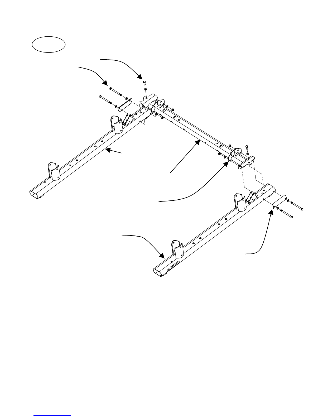
Step 1: Attach the Right Base Beam, Left Base Beam,
Weight Stack Mount, two Cable Anchor Pl a tes,
And two Base Beam Brackets using:
Four (M10 Locknuts)
Note: “(Blue Dot)” means there is a blue dot of thread locking compound on the bolt
thread.
(Finger Tighten Only)
Page 5
Two (M10 x 25 Hex Bolts (Blue Dot)
Four (M10 x 125 Hex Bolts)
Ten (M10 Flat Washers)
Page 9
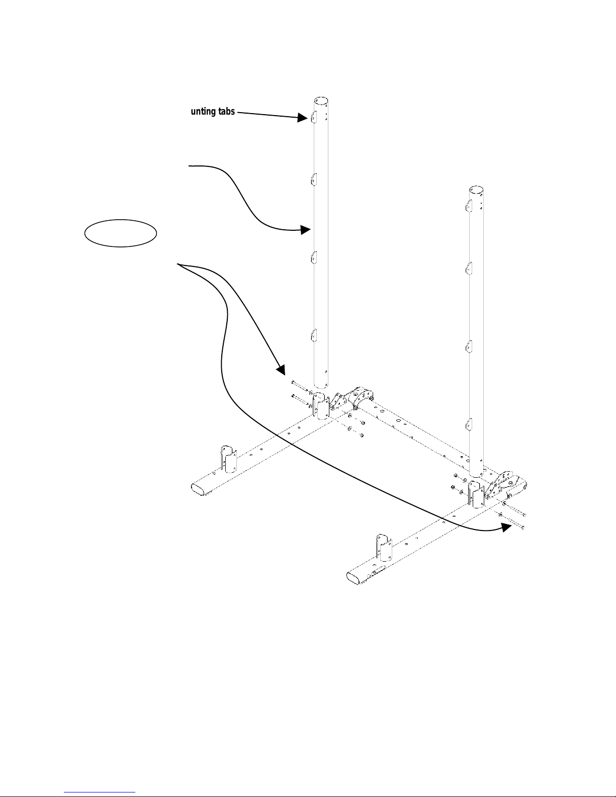
Weight Rack mounting tabs
Main Upright
Step 2
4 – M10 x 105 Hex Bolts
8 – M10 Flat Washers
4 – M10 Locknuts
Step 2: Attach two Main Uprights to the rear of the Left and Right Four (M10 x 105 Hex Bolts)
Right Base Beams (orient all Uprights with the four Weight
Rack mounting tabs toward the middle of the machine
and near the top) using:
(Finger Tighten Only)
Page 6
Eight (M10 Flat Washers)
Four (M10 Locknuts)
Page 10
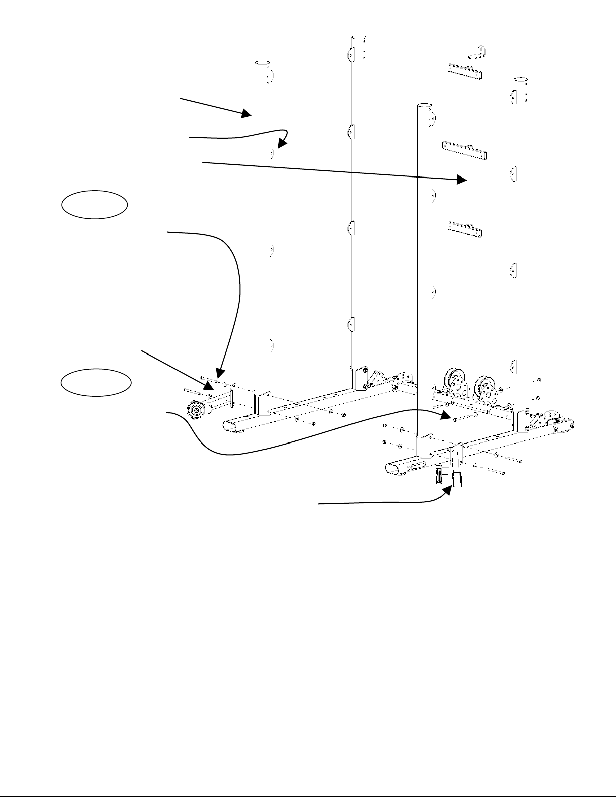
Main Upright
Weight Rack mounting tabs
Row Pulley Mount
Step 3
4 - M10 x 110Hex Bolts
8 - M10 Flat Washers
4 – M10 Locknuts
Lower Right Cable Column Mount
Step 4
2 – M10 x 100 Hex Bolts
4 – M10 Flat Washers
2 – M10 Locknuts
Lower Left Cable Column Mount
Step 3: Attach the two front Main Uprights, Lower Right Cable Four (M10 x 110 Hex Bolt s)
Column Mount, and Lower Left Cable Column Mount to Eight (M10 Flat Washers)
the Left and Right Base Beams using: Four (M10 Locknuts)
(Orient all Uprights with the four Weight Rack mounting tabs
toward the middle of the machine and near the top as sho wn )
Note: Finger Tighten Only
Step 4: Attach the Row Pulley Mount to the Weight Stack Mount Two (M10 x 100 Hex Bolts)
using: Four (M10 Flat Washers)
Two (M10 Locknuts)
(Finger Tighten Only)
Page 7
Page 11
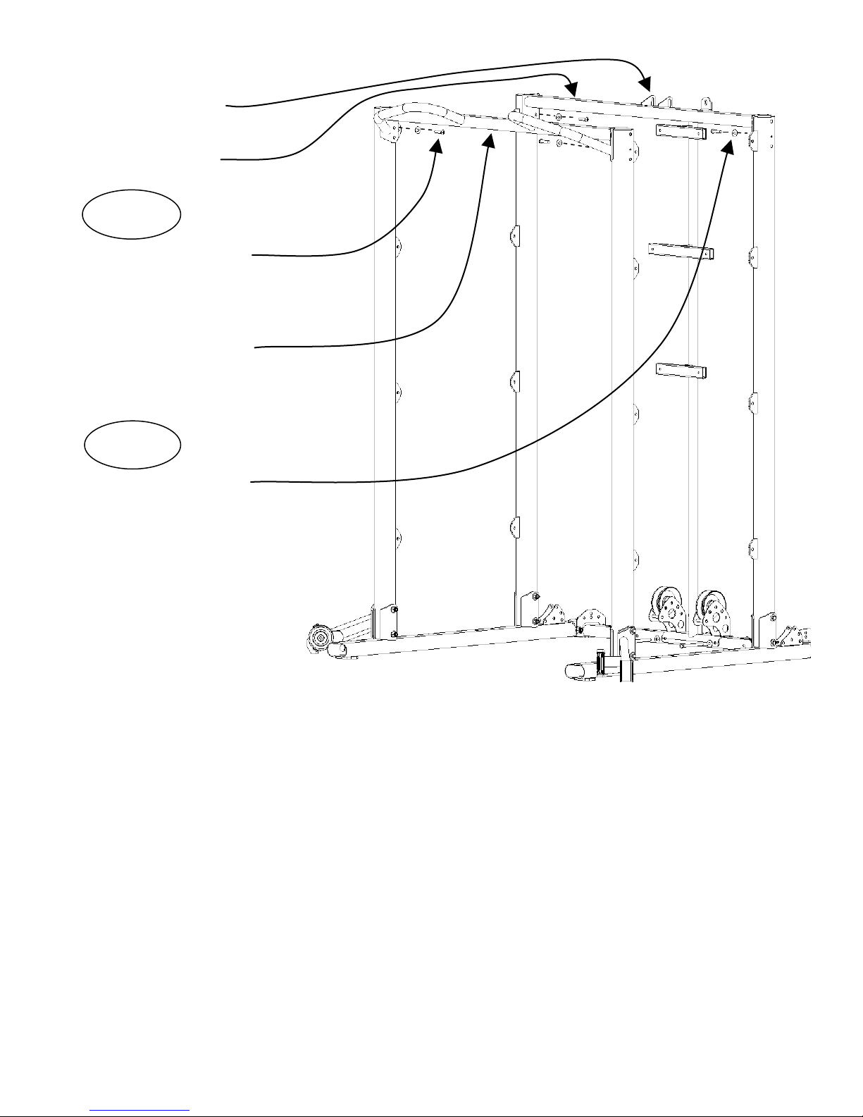
Note: Two tabs to rear
Rear Cross Brace
Step 5
2 - M8 x 20 Hex Bolts
2 - M10 Flat Washers
Pull-Up Bar Cross Brace
Step 6
2 - M8 x 20 Hex Bolts
2 - M8 Flat Washers
Step 5: Attach the Pull-Up Cross Brace to top of front Two (M8 x 20 Hex Bolts)
Main Uprights using: Two (M8 Flat Washers)
(Finger Tighten Only)
Step 6: Attach the Rear Cross Brace to the top of Two (M8 x 20 Hex Bolts)
the rear Main Uprights using: Two (M8 Flat Washers)
Assure the two tabs in the center of the Rear Cross Brace are facing towards the back of the
machine.
(Finger Tighten Only)
Page 8
Page 12

Right Top Beam
Left Top Beam
Top Weight
Top Right Cable Column Mount
Step 7
2 - M10 x 100 Hex Bolts (Blue Dot)
2 - M10 x 110 Hex Bolts
6 - M10 Flat Washers
2 - M10 Locknuts Top Left Cable Column Mount
Step 8
Stack Mount
2 - M10 x 100 Hex Bolts (Blue Dot)
2 - M10 x 110 Hex Bolts
6 - M10 Flat Washers
2 - M10 Locknuts
Step 9
1 - M12 x 25 Hex Bolt
1 - M10 x 45 Hex Bolt
2 - M10 Flat Washers
1 - M10 Locknut
Step7: Attach the Left Top Beam and Top Left Cable Column Mount Two (M10 x 100 Hex Bolts
to the left Main Uprights AND the Right Top Beam and Top with Blue Dot)
Right Cable Column Mount to the Right Main Uprights using: Two (M10 x 110 H ex Bolts)
Six (M10 Flat Washers)
(Finger Tighten Only) Two (M10 Locknuts)
Step 8: Attach the Top Weight Stack Mount to the Rear Main Two (M10 x 100 Hex Bolts
Uprights using: with Blue Dot)
Two (M10 x 110 Hex Bolts)
Six (M10 Flat Washers)
(Finger Tighten Only) Two (M10 Locknuts)
Step 9: Install the M12 x 25 hex bolt in the top of the One (M12 x 25 Hex Bolt)
Row Pulley Mount and adjust it to it’s minimum height. One (M10 x 45 Hex Bolt)
Attach the Top Weight Stack Mount to the Row Pulley Two (M10 Flat Washers)
Mount with the M10 x 45 hex bolt. Insert this bolt from One (M10 Locknuts)
front to go out the back, using:
(Wrench Tighten Steps 1 - 9)
Page 9
Page 13

Lat Attach Bracket,
Upper and Lower
Rear Cross Brace
Lat Attachment
3 ½” Dia. Pulleys
Step 10
2 - M10 x 155 Hex Bolts
1 - M10 x 105 Hex Bolt
6 - M10 Flat Washers
3 - M10 Locknuts
Step 10: Assure the M12 Hex Bolt from STEP 9 is installed in the top of the Row Pulley Mount and
adjusted to the minimum height. Attach the Lat Attachment and two 3 ½” diameter pulleys to
the top of the Weight Stack Mount and Rear Cross Brace using:
Two (M10 x 155 Hex Bolts)
One (M10 x 105 Hex Bolt)
Six (M10 Flat Washers)
Three (M10 Locknuts)
2 - M10 x 60 Button Head Bolts
2 - M10 x 25 Hex Bolts
8 - M10 Flat Washers
4 – M10 Locknuts
Now install two Brackets supporting the Lat Attachment to Pull Up Cross Brace with the Button Head
Bolts, pointing up through the Pull Up Cross Brace. Use M10 x 60 Button Head Bolts with the locknut
on top of the Lat Attachment. Use the M10 x 25 Hex Bolts to secure the height adjustment of the
brackets together using: Two (M10 x 60 Button Head Bolts)
Two (M10 x 25 Hex Bolts)
Eight (M10 Flat Washers)
Four (M10 Locknuts)
(Wrench Tighten Now)
Note: Adju st the M12 x 25 Hex Bolt in the top of the Row Pulley Mount up
to support the load of the Lat Attachment.
Page 10
Page 14

Step 10: Lat Attachment, Low Profile Option
For a lower profile machine, remove the two
Brackets and bolt the Lat Attachment directly One (M10 x 95 Button Head Bolt)
to the Pull-Up Cross Brace with one M10 x 95 Two (M10 Flat Washers)
Button Head Bolt, pointing up through it using: One (M10 Locknuts)
(Wrench Tighten Now)
Step 11
2 - M8 x 25 Hex Bolts
4 – M8 flat Washers
2 – M8 Locknuts
2 - M12 x 30 Hex Bolts
4 - M12 Flat Washers
2 - M12 Locknuts
Pull Up Bar
Step 11: Attach the Pull-Up Bar to the Lat Attachment using: Two (M12 x 30 Hex Bolts)
Four (M12 Flat Washers)
Two (M12 Locknuts)
Two (M8 x 25 Hex Bolts)
Four (M8 Flat Washers)
Two (M8 Locknuts)
(Wrench Tighten Now)
Page 11
Page 15

Weight Stack
Guide Rods
Shroud Plate Spacers
Shroud Mount Plates
NOTE: The back side of the Shroud
Mount Plate has only one hole.
Step 12
4 - M10 x 60 Hex Bolts, Blue Dot
4 - M10 x 95 Hex Bolts
12 - M10 Flat Washers
4 - M10 Locknuts
Mount
Step 12: Attach four Guide Rods to the Weight Stack Four (M10 x 95 Hex Bolts)
Mount using: Eight (M10 Flat Washers)
Four (M10 Locknuts)
(Wrench Tighten Now)
Attach two Shroud Plate Spacers and two Shroud Mount Four (M10 x 60 Hex Bolts
Plates to the Weight Stack Mount using: with Blue Dot)
Four (M10 Flat Washers)
NOTE: Be sure smooth flat side of plate is on top and
the single hole is to t he back of the machine.
(Finger Tighten Only)
Page 12
Page 16

Step 13
Selector Stem/Top Weight Assembly
Front of Weight Plate has recessed area for
Weight Plate Number Stickers
Weight Plate
Bottom of weight plate has three feet
Top Weight Pulley and M12 Jam Nut
Rubber Donuts
Weight Stack Risers
Shroud Plates
NOTE: Before beginning Step 13: If optional 200 lb. heavy stack is being assembled, eliminate the
Weight Stack Risers. This space will be taken up by 5 extra Weight Plates.
Step 13: Slide Weight Stack Risers down the Guide Rods and onto the Shroud Plates. Next, slide the
Rubber Donuts down the Guide Rods until sitting on the Weight Stack Risers. Slide each Weight
Plate down the Guide Rods until all 15 Weight Plates (20 Plates for heavy stack) are resting on
the Rubber Donuts. Be sure that all Weight Plates are facing toward front of the machine. F ront
Of Weight Plate is indicated by recessed area for weight stack numbers. Next, slide Selector
Stem/Top Weight Assembly down the Guide Rods and onto Weight Stack.
Repeat with the second Weight Stack.
Attach the Top Weight Pulley Assemblies and Jam Nuts on the Selector Stems, verifying that bolts
are threaded completely into the Selector Stems with Locknuts on the Pulleys bolts facing towards
front of the gym using:
Two (M12 Jam Nuts)
(Wrench Tighten Jam Nuts)
IMPORTANT! Top Weight Pulley Assemblies must be fully threaded into the Weight Stack
Selector Stems with the Jam Nuts tightened securely before use. Failure to do so may
cause the Pulley A s semblies to come loose from weights and can cause injury.
Page 13
Page 17

Weight Stack Shroud Mounts
Step 14
4 - M10 x 45 Hex Bolts
8 - M10 Flat Washers
4 - M10 Locknuts
Step 14: Install the two Weight Stack Shroud Mounts. One at a time, Four (M10 x 45 Hex Bolts)
position the Weight Stack Shroud Mounts at the top of the Eight (M10 Flat Washers)
Guide Rod pairs. Slide these down the Guide Rods and Four (M10 Locknuts)
secure in position using:
(Wrench Tighten Steps 12 And 14 Now)
Page 14
Page 18

Right Cable
Right Top Cable Column Mount Left Top Cable Column Mount
Step 15
4 - M10 x 60 Hex Bolts
8 - M10 Flat Washers
4 - M10 Locknuts
Left Cable Column Slider
Cable Column Tubes
Column Slider
Lower Right Cable Column Mount Lower Left Cable Column Mount
Step 15: Identify one of the Cable Column Tube’s upper end,
end with the slotted holes). Assemble the Right Cable
Pop-pin aligns with the holes in the tube. Attach the Right Two (M10 x 60 Hex Bolts)
Cable Column Tube Assembly to the Right Upper and Lower Four (M10 Flat Washers)
Cable Column Mounts us ing: Two (M10 Locknuts)
Repeat the procedure for the Left Cable Column Assembly Two (M10 x 60 Hex Bolts)
Using: Four (M10 Flat Washers)
Two (M10 Locknuts)
Column Slider onto the Cable Column Tube. Make sure the
(the
NOTE: Make sure all four bolts are installed from the front to the back as shown.
(Wrench Tighten All Previous Steps Now)
Page 15
Page 19

Pulley #2
Pulley #1
Pulley #4
Pulley #7
Cable End
Cable Column
Slider Assy.
Upper Cable inside Left Top
Beam tube
Pulleys #8 and #9
Floating Pulley Assy.
Pulley #10
Pulleys #5 and #6
Step 16
1 - Upper Cable
1 - 3 ½” Dia. Pulley
1 - M10 x 70 Hex Bolt
2 - 1/2” Step Spacers
Upper Cable inside tube
1 - M10 Locknut
Pulley #3
Start Upper Cable here
Floating Pulley Assy.
Cable En d Detail
1 - Plastic Ball
1 - “U” Bracket
1 - Spring Clip
1 - M6 x 20 Button Head Bolt
1 - M6 Flat Head Nut
Step 16: Select one of the Upper Cables. Position the Left Cable Column Slider Assembly at a comfortable
working height. Slide the retainer “O” Ring up the cable about 3 inches from the cable end for
installation (this allows the cables to feed through their routings easier). Remove one Jam Nut from
the cable bolt and insert the cable bolt, threaded end down, through the bracket on the Cable Column
Slider Assembly. Return the Jam Nut to the cable bolt (below the bracket) to secure it on the Left
Cable Column Slider Assembly. Continue feeding the cable up around Pulley #1, into and through the
Left Top Beam, going out at the rear. Make sure you route the cable to the correct side of all cable
guides and pins. Failure to route the cable properly will result in damage to the cable. Now route the
cable over Pulley #3 and down through the Floating Pulley with Guide Bushing, Pulley #4. Make sure
the Guide Bushing is facing towards the rear of the m achine. Route the cable up over Pulley #5 and
Pulley #6 and down to the Weight Stack Top Pulley #7. Route the cable up over Pulleys #8 and #9
and then down through the second Floating Pulley #10. Complete the cable ro uting going up over
Pulley #11 at the rear of the Lat Attachment and forward out through the Swivel Pulley Assembly at
the front of the Lat Attachment. Attach Cable End by placing one Plastic Ball on the end of the cable,
next slide the end of the cable into the slot of the Cable “U” Bracket. Attach the Spring Clip to the “U”
Bracket using a M6 x 20 Button Head Bolt and M6 Flat Head Nut. Slide the retainer “O” Ring tight
against the Plastic Ball. Final ly, ins tall Pulley #2 in the Top Beam per abo ve detail using:
One (M10 x 70 Hex Bolt) One (Plastic Ball)
Two (1/2” Step Spacers) One (“U” Bracket)
One (M10 Locknut) One (Spring Clip)
One (M6 x 20 Button Head Bolt)
One (M6 Flat Head Nut)
(Wrench Tighten Now)
Floating Pulley Assy. with
Guide Bushing
Page 16
Page 20

Pulley #3
Pulley #2
Floating Pulley Assy. with
Guide Bushing
Start cable here
Cable Column
Slider Assy.
Pulley #4
Cable inside tube
Pulleys #5 and #6
Pulleys #8 and #9
Pulley #7
Floating Pulley Assy.
Pulley #10
Cable End
Pulley #1
Pulley #11
Step 17
1 - Upper Cable
1 - 3 ½” Dia. Pulley
1 - M10 x 70 Hex Bolt
2 - 1/2” Step Spacers
1 - M10 Locknut
Cable End detail
1 - Plastic Ball
1 - “U” Bracket
1 - Spring Clip
1 - M6 x 20 Button Head Bolt
1 - M6 Flat Head Nut
Step 17: Install the Upper Cable on the right side of the machine. Repeat the installat ion sequence in
Step 16, but this time on the right side of the machine using:
One (Upper Cable) One (Plastic Ball)
One (3 ½” Dia. Pulley) One (“U” Bracket)
One (M10 x 70 Hex Bolt) One (Spring Clip)
Two (1/2” Step Spacers) One (M6 x 20 Button Head Bolt)
One (M10 Locknut) One (M6 Flat Head Nut)
(Wrench Tighten Now)
Page 17
Page 21

M10 x 55 Hex Bolt (Blue Dot)
1/2” Step Spacer
Lower Cable inside tube
M10 x 50 Hex Bolt
M10 x 35 Hex Bolt
Cable Anchor Plate
Lower Cable “U” Bracket
and Anchor Plate
Floating Pulley Assy.
with Guide Bushing
Front Pulley
Cable Column Mount Pulley
Step 18
1 - Lower Cable
1 - M10 x 35 Hex Bolt
1 - M10 x 50 Hex Bolt
1 - M10 x 55 Hex Bolt (Blue Dot)
4 - M10 Flat Washers
2 - M10 Locknut
1 - 1/2” Step Spacer
1 - Plastic Ball
1 - “U” Bracket
1 - Spring Clip
1 - M6 x 20 Button Head Bolt
1 - M6 Flat Head Nut
Step 18: Select a Lower Cable (with “U” Bracket). Lay it out assuring it is not kinked. Attach the “U”
Bracket to the Cable Anchor Plate upper center hole. Route the cable up through the Floating Pulley
Assembly with Guide Bushing, then down around the rear pulley position and into the Base Beam. Push
the cable forward through the Base Beam past the front pulley position. Route the cable out through
the smaller hole and up around
pulley and
seated in their grooves. Route the cable up the Cable Column and between the Dual Pulleys on the
Cable Column Slider. To secure the Cable End, pla ce one Plastic Ball onto the end of the cable. Next
slide the cable end into the slot of the Cabl e End “U” Bracket. Finally, attach the Spring Clip to the “U”
Bracket using the M6 x 20 Button Head Bolt and M6 Flat Head Nut. Slide the retainer “O” Ring tight
against the Plastic Ball to complete using:
One (M10 x 35 Hex Bolt) One (Plastic Ball)
One (M10 x 50 Hex Bolt) One (“U” Bracket)
One (M10 x 55 Bolt (Blue Dot) One (Spring Clip)
Four (M10 Flat Washers) One (M6 x 20 Button Head Bolt)
Two (M10 Locknuts) One (M6 Flat Head Nut)
One (1/2” Step Spacer)
the lower cable retainer tab only. Install the front and rear Pulleys assuring that the cable is
(Wrench Tighten Now)
the Lower Cable Column Mount Pulley, capturing the cable between the
Page 18
Page 22

Start cable here,
Cable Anchor
Floating Pulley Assy
With Guide Bushing
Front Pulley
Cable End Detail
M10 x 35 Hex Bolt
M10 x 50 Hex Bolt
M10 x 55 Hex Bolt
1/2" Step Spacer
Step 19
1 - Lower Cable
1 - M10 x 35 Hex Bolt
1 - M10 x 50 Hex Bolt
1 - M10 x 55 Hex Bolt (Blue Dot)
4 - M10 Flat Washers
2 - M10 Locknuts
1 - 1/2” Step Spacer
1 - P lastic Ball
1 - “U” Bracket
1 - Spring Clip
1 - M6 x 20 Button Head Bolt
1 - M6 Flat Head Nut
Cable inside tube
Step 19: Repeat instructions from Step 18 to install the right side Lower Cable.
One (M10 x 35 Hex Bolt) One (Plastic Ball)
One (M10 x 50 Hex Bolt) One (“U” Bracket)
One (M10 x 55 Bolt (Blue Dot) One (Spring Clip)
Four (M10 Flat Washers) One (M6 x 20 Button Head Bolt)
Two (M10 Locknuts) One (M6 Lock Nut)
One (1/2” Step Spacer)
(Wrench Tighten Now)
“U” Bracket and
Page 19
Page 23

Floating Pulley Assy.
Cable End Detail
Row Pulley Mount
Left Row Cable
Step 20
1 – Row Cable
1 - Plastic Ball
1 - “U” Bracket
1 - Spring Clip
1 - M6 x 20 Button Head Bolt
1 - M6 Flat Head Nut
Start Left Row Cable here
Step 20: Select the two Row Cables and lay them out straight assuring they are not kinked. Remove one
Jam Nut from the cable end bolt. Insert the bolt into the bracket at the bottom of the Row Pulley
Mount. Reattach the Jam nut. Route the cable up through the Floating Pulley Assembly and back
down around the back side of the Wide Pulley and out the front at the bottom of the Row Pulley
Mount. Be sure the cable goes between the Wide Pulley and cable retainer pin. Complete the
cable end by sliding a Plastic Ball onto the end of the cable. Next slide the cable end into the side
of the Cable “U” Bracket. Finally, attach the Spring Clip to the “U” Bracket using a M6 x 20 Button
Head Bolt and M6 Flat Head Nut. Slide the retainer “O” Ring tight against the Plastic Ball to
complete using:
One (Row Cable)
One (Plastic Ball)
One (“ U” Br ac k e t)
One (Spring Clip)
One (M6 x 20 Button Head Bolt)
One (M6 Flat Head Nut)
(Wrench Tighten Now)
Page 20
Page 24

Cable End Detail
Step 21
1 - Row Cable
1 - Plastic Ball
1 - “U” Bracket
1 - Spring Clip
1 - M6 x 20 Button Head Bolt
1 - M6 Flat Head Nut
Row Pulley Mount
Right Row Cable
Row Cable End
Step 21: Repeat all of Step 20 on the right side of the gym using:
One (Row Cable)
One (Plastic Ball)
One (Spring Clip)
One (“U” Bracket)
One (M6 x 20 Button Head Bolt)
One (M6 Flat Head Nut)
(Wrench Tighten Now)
Start Right Row Cable Here
Page 21
Page 25

Bushing in Floating
Pulley Assembly
Hook on bottom of Top
Weight Stack Mount
Base Beam
Guide Cable
Step 22
Attach Guide Cables
Step 22: Feed the small end of the Guide Cable up through the bushing in the Floating Pulley Assembly
and attach the end to the hook on the bottom of the Top Weight Stack Mount. Insert the bolt
end into the threaded hole in the Base Beam. Tighten the bolt so the Guide Cable is taught, but
do not over tighten. Tighten the jam nut.
Repeat this process for the Guide Cable on the other side of the machine.
Page 22
Page 26

Step 23
16 - M10 x 25 Hex Bolts
32 - M10 Flat Washers
16 - M10 Locknuts
Step 23: Attach the four Weight Rack Plates onto the outer sides of the mounting tabs on the
Main Uprights with the “Hooks” pointing up using:
Sixteen (M10 x 25 Hex Bolts)
Thirty Two (M10 Flat Washers)
Sixteen (M10 Locknuts)
(Wrench Tighten Now)
Page 23
Page 27

Exercise Placard
Row Pulley Mount
Step 24
6 - M6 x 35 Button Head Bolts
6 - M6 Flat Washers
6 - M6 Locknuts
Step 25
6 - End Caps
Step 24: Attach the Exercise Placard to the Row Pulley Mount using:
Six (M6 x 35 Button Head Bolts)
Six (M6 Flat Washers)
Six (M6 Locknuts)
Note: Place the washers under the nuts only. No washers under the head of the button head bolts.
(Wrench Tighten Now)
Step 25: Install End Caps in the front of the Top and Base Beams, and the rear of the Base Beams.
Page 24
Page 28

While sliding the Shroud Bracket
the back of the shroud
Shroud Bracket
Lower Shroud
Mount Plate
Shroud Plate Connector Pins
Shroud Tightening Knobs
Shroud Plate Connector
Pins
Upper Shroud
Mount Plate
Step 26
into the pocket of the Fabric
Shroud, align the hole in the
bracket with square opening in
Step 26:
Slide a Shroud Bracket into the pocket at each end of a Fabric Shroud so the hole in the back of the
bracket aligns with the square opening in the shroud. For a clean look, the seam or fabric overlap
should be facing inward.
Slide the upper end of the Fabric Shroud, with Shroud Bracke t inserted, over the upper Shroud Mount
Plate. Secure the shroud to the plate with three Shroud Plate Connector Pins.
Slide the lower end of the Fabric Shroud, with Shroud Bracket inserted, over the lower Shroud Mount
Plate. Secure the shroud to the plate with three Shroud Plate Connector Pins.
Turn the Shroud Tightening Knobs to tighten the Fabric Shroud and remove any possible wrinkles.
Repeat this process for the second Fabric Shroud.
Page 25
Page 29

Step 27
Step27: Initially adjus t the four cable bolts to 1” between the top of the bolt and the
bracket it is attached too and Wrench Tighten the Jam Nuts.
Start with one Cable and adjust the slack out. Then do the same with
the other three Cables. Assure the cables routing is clear and in the
grooves of all pulleys.
There has to be a minimum of one Bolt thread showing below
the Nuts after adjustment.
At this point it is necessary to seat the ca b les. Start by
verifying that cables are centered in the grooves of all
pulleys and clear of all guides and potential obstructions.
Shake Down, select a weight that you can comfortably
handle. Perform a standard ex ercise and hold the first
repetition. Now, lightly bounce the weights up and down
several times. This will seat the cables into the pulleys
and prepare the Smith Cage System for final adjustments.
Readjust the cables with the Cable Bolts to remove any Cable Clevis
new slack. If after readjusting the cables there is still
excess slack, you can adjust more slack out by moving
the clevis on the end of the Lower Cables to the lower
hole in the Cable Anchor.
Lower Hole
If after adjusting cable length(s) as noted above and the cable
appears to be too short, remove the Top Weight Pulley, screw out
the “U” bracket one to two full turns, then retighten the Jam N ut ,
and re-attach the pulley. Make sure the Locknut on the Pulley bolt
is facing toward the back of the cage.
Page 26
Page 30

EXPLODED VIEW
Exploded View not available at this time.
Please contact customer service at 1-877-738-1728 for assistance
or a copy.
Page 27
Page 31

Weight
DECAL REFERENCE
877-738-1729
;
PAGE 28
Number
Stickers
8,870,718.
Page 32

DECAL PLACEMEN T
Serial
“NOTICE”
“WARNING”
“DANGER”
“INSPIRE”
Patent
Label
Number
Label
Label
Label
on both sides
of safety tiers
Label
Page 29
Label
Page 33

ACCESSORIES
• 4 Ring “D” Handles – two pieces
• Ankle Strap – one piece
• “D” Handle / Ab Strap – two pieces
• Pull-up Assist Strap – one piece
Smith Cage System OPTIONS
• SCS-102 (SMITH MACHINE OPTION)
• Two Heavy Stacks (50lbs. each)
• Ab Crunch Bar
Training Tips
CONSULT A PHYSICIAN BEFORE STARTING ANY EXERCISE PROGRAM
1. Always warm up before you start weight training. T h is h elps get
your muscles warm and prevents injury. You can warm up with light
cardio or by doing a light set of each exercise before going to heavier
weights.
2. Control the weight. Always work with a weight that you can handle
through a full range of motion. Slow and steady movements are
recommended.
3. Breathe. Don’t hold your breath during your set. Holding your
breath builds internal pressure which increases your chance for broken
blood vessels, as well as a hernia.
4. Sit up straight. Pay attention to your posture and keep everything
straight. Engage your abs in every movement to keep balanced and
protect your spine.
Page 30
Page 34

GENERAL MAINTENANCE INFORMATION
• Periodically inspect the cables for splitting, cracking or fraying. Also,
watch for bulging or flat areas in the cable.
• Immediately replace cables at the first signs of damage or wear. Never
use equipment with damaged or worn cables.
• Cables naturally stretch over time, so check cable slack periodically and
adjust cable tension as needed.
• Regularly inspect product for loose hardware.
• Do not use or store equipment outdoors.
• Inspect spring clips, swivels, handles and weight stack pin for wear or
damage. If wear or damage exists, replace immediately.
• Locate and familiarize yourself with all warning decals on the equipment.
• Replace damaged or worn uphols tery immediately.
• Periodically wipe down guide rods with a dry cloth and re-apply a thin
coat of a teflon-based lubricant.
Page 31
Page 35

MAINTENANCE SCHEDULE
Inspect: Links, Pull Pins,
Weight Stack Pins
Clean and Lubricate:
based lubricant
ROUTINE
Spring Clips, Swivels,
Clean: Upholstery
Inspect: Cables and
their Fittings
Inspect: Tautness of all
Shrouds
Inspect: Accessory Bars
and Handles
Inspect: All Decals
HOME
MAINTENANCE
WEEKLY
WEEKLY
WEEKLY
WEEKLY
3 MONTHS
3 MONTHS
ENTRY DATE
Inspect: All Nuts and
Bolts. Tighten if Needed
Inspect: Anti-Skid
surfaces
Guide Rods with a Teflon
Lubricate: Seat Sleeves
and all Plastic Slides
Clean and Wax: All
Glossy Finishes
Replace: Cables, Belts
and Connecting Parts
3 MONTHS
3 MONTHS
3 MONTHS
3 MONTHS
YEARLY
2 YEARS
Page 32
Page 36

Warranty.
Page 33
This Warranty a p plie s to Inspire Strength p r oducts manufactured or distributed by Health In Motion LLC.
CONSUMER USE: LIGHT-COMMERCI A L U SE:
LIMITED LIFETIME FRAME: LIMITED LIFETIME FRAME:
Includes Frame and Welds Includes Frame and Welds
LIMITED LIFETIME PARTS: 10 YEAR PARTS:
Includes Upholstery, Hardware, etc. Includes Upholstery, Hardware, etc.
LIMITED LIFETIME MOVING PAR T S: 10 YEAR MOVING PARTS:
Includes Pulleys, Cables, etc. Includes Pulleys, Cables, etc.
PLEASE NOTE THAT NOT ALL INSPIR E PRO DUCTS ARE MADE F O R LIGHT-COMMERCIAL USE
Refer to your Owner’s Manual or consult with y ou fitness product dealer to establish if a Product is made for lightcommercial use or not. Using a non-commercial product in a commercial setting can result in s er ious injury or death!
Health In Motion w a r rants that the Product you have purcha s ed for light-commerc ia l, personal, family or household
use from Health In Motion LLC or from an authorized Health I n Motion reseller is f ree from defects in m a terials or
workmanship under nor mal us e during the warranty period. You r s a les r ec eipt, showing the date of purc has e of the
Product, is you r proof of the date of purchase. This warran ty extends only to you, the original pur c haser. It is not
transferable to anyone w ho subsequently purchases the P roduct from you. It excludes expenda ble pa r ts such as paint
and finish. This Warranty becomes VALID ONLY if the Produ c t is assembled / installed according to th e instructions /
directions included with the Product.
Replacement and repair of parts.
During the warranty period Health In Motion will, at no add itional charge, re pa ir or replace the Prod uct if it becomes
defective, malfunctions, or other wise fails to conform with this Warr an ty under normal light-commercial, personal,
family, or hou s ehold use. In repairing the product Health In Motion may replace defective parts with, at the option of
Health In Motion, s erviceable used parts that are equivalent to new parts in performance, or new parts. All exchanged
parts and Produc ts replaced under this warranty will become the property of Health In Motion. H ealth In Motion
reserves the righ t to c hange manuf a cturers and or specifica tion of any part to c over any existing warranty.
Service procedures.
To obtain warran ty parts, you must r eturn the parts to Health I n Motion or an authorized Health In Motion retailer in
its original container (or equivalent). You must pre-pay any shipping charges, taxes, or any other charges associated
with transportation of the Produc t. In addition, you are r esponsible for insuring any Product shipped or returned. Y ou
assume the risk of loss during shipment. You must present Health In Motion with proof-of-purchase documents
(including the date of purchase, Model, and Serial Number ) . Any evidence of alteration, eras ing or forgery of proof of-purchase doc uments will be caus e to void this Warranty. Register your warranty online v is it www.inspirefitness.net
Conditions and Exceptions.
This Warranty doe s not extend to any Pr od uct not purchased f r om Health In Motion LLC or from an authorized He a lth
In Motion reseller. This Warra nty does not extend to any Produ c t th a t h a s been da m a ged or r endered defective; (a)
as a result of accident, misuse, or abuse; (b) by the use of parts not manufactured or sold by Health In Motion; (c) by
modification of the Product; (d) as a result of service b y anyone other th an Health In Motion, or an au thorized Health
In Motion warranty service provider; (e) product that has not been proper ly maintained (follow m aintenance schedule
found on produc t). Should any product submitted for Warra nty service be found to be ineligible, an estimate of repair
cost will be furnished and th e r epa ir will be made if requested by you upon Health In Motion receipt of payment or
acceptable arrangement of payment.
Disclaimer
EXCEPT AS EXPRESSLY SET FORTH IN THIS WARRANTY HEALTH IN MOTION MAKES NO OTHER WARRANTIES;
EXPRESSED OR IMPLIED INCLUDING ANY IMPLIED WARRANTIES OF MERCHANTABILITY AND FITNESS FOR A
PARTICULAR PURPOSE. HEALTH IN MOTION EXPRESSLY DISCLAIMS ALL WARRANTIES NOT STATED IN THIS
WARRANTY. ANY IMPLIED WARRANTIES THAT MAY BE IMPOSED BY LAW ARE LIMITED TO THE TERMS OF THIS
WARRANTY. NEITHER HEALTH IN MOTION NOR ANY OF ITS AFFILIATES SHALL BE RESPONSIBLE FOR INCIDENTAL
OR CONSEQUENTIAL DAMAGES. HEALTH IN MOTION IS NOT RESPOSIBLE FOR THE REPAIR OR REPLACEMENT OF
ANY PARTS THAT HEALTH IN MOTION DETERMINES HAVE BEEN SUBJECTED AFTER THE DATE OF MANUFACTURE TO
ALTERATION, NEGLECT, ABUSE, MISUSE, NORMAL WEAR & TEAR, ACCIDENT, DAMAGE DURING TRANSIT OR
INSTALLATION, FIRE, FLOOD, OR ANY ACT OF GOD. SOME STATES DO NOT ALLOW LIMITATIONS ON HOW LONG AN
IMPLIED WARRANTY LASTS OR THE EXCLUSION OR LIMITATION OF INCIDENTAL OR CONSEQUENTIAL DAMAGES, SO
THE ABOVE LIMITATIONS OR EXCLUSION MAY NOT APPLY TO YOU. This Warranty gives you specific legal rights and
you may also hav e other rights that may vary from state to state. This is the only expr e s s warranty applica b le to
Health In Motion’s “Inspire” bra nded strength produc ts . Health In Motion n e ither assumes nor au thorizes anyone to
assume for it any other express warranty.
 Loading...