

Page 1
Inspire Home Automation
www.inspirehomeautomation.co.uk
contact@inspirehomeautomation.co.uk
01202 798390
1
NS1002 Installation Guide Rev 1.4
WARNING Electricity is dangerous. Before commencing work, ensure that you read and understand these instructions and isolate
the relevant circuit. This product should only be installed by a qualified electrician or heating engineer and should be installed
in accordance to BS 7671 (IEE Wiring Regulations), or to another equivalent standard.
CAUTION: High Voltage Wires
The NS1002 series is designed to control a typical domestic central heating system. The Relay module
can switch two independent channels. This would usually be the Central Heating and the Hot Water.
The central heating channel is switched on and off in response to commands from the supplied Wireless
Thermostat.
The Hot Water channel is switched on and off at the programmed time intervals that the user sets.
Whats in the box
Introduction
1 x Assembled Room Thermostat consisting of
1 x Room Thermostat
1 x Wall Mount
1 x Assembled Relay Module consisting of
1 x Control Board
1 x Wall Mount
1 X Front Cover
1 x Gateway
1 x Network Cable
1 x Power Supply
1 x Thermostat screw pack
1 x Relay Module Screw Pack
2 x Batteries
Gateway Room Thermostat
Relay Module
Relay Module
Screw Pack
Thermostat
Screw Pack
Batteries Network CablePower Supply
Page 2

2
Inspire Home Automation
www.inspirehomeautomation.co.uk
contact@inspirehomeautomation.co.uk
01202 798390
Radio Signal
Specifications
Relay Module
Power Supply: 230V~ 50...60Hz, 2.5W (Max)
Switch Type: 2 x SPDT
Switch Rating: 3 Amps Total load on all Channels
Radio Frequency: 2.4 GHz
Dimensions: 160 x 100 x 18 mm (35mm including recessed wallmount)
Room Thermostat
Thermostat Power Supply: 2x AA batteries
Controllable Temperature Range: 10 – 30°C
Frost Protection: Programmable from 0.5 - 30°C
Radio Frequency: 2.4 GHz
Dimensions: 119 x 88 x 22 mm
Gateway
Power input: 5V 1A
Internet Connection: Wired Ethernet Cable
Radio Frequency: 2.4 GHz
Dimensions: 94 x 79 x 24 mm
Consideration for location of your new system components and the affects that this may have on the radio
signal is extremely important. The signal will travel between units in a straight line and will degrade both
with distance and (much more importantly) objects that it has to pass through.
The Relay Module needs to connect to the Wireless Internet Gateway
The Thermostat needs to connect to EITHER the Wireless Internet Gateway OR the Relay Module (It will
automatically select the best signal path)
Every house is different and this is NOT a gaurantee, but as a guide, the units should be able to
communicate with each other through two single skin brick or stud walls.
If the above is not possible, then you may need to consider adding our repeater(s) into the system, or
moving one or more of the system components.
Also, the radio can be adversely affected by large metal objects such as your boiler, radiators and mirrors.
For best performance, ensure that your units are placed at least 1 metre away from such objects.
Page 3
3
Inspire Home Automation
www.inspirehomeautomation.co.uk
contact@inspirehomeautomation.co.uk
01202 798390
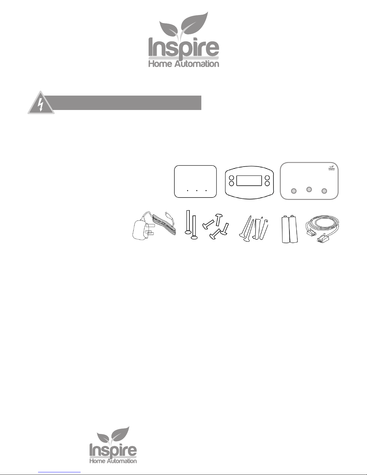
The above image shows the path that the signal will travel to communicate between the 3 units.
This is an example of badly positioned items for the following reasons.
The Relay Module is position under the boiler
The signal between the Relay Module and Gateway needs to travel through three walls, a
staircase and various kitchen objects, including Units, Oven and Fridge.
Kitchen
Boiler
Relay
Module
Gateway
Thermostat
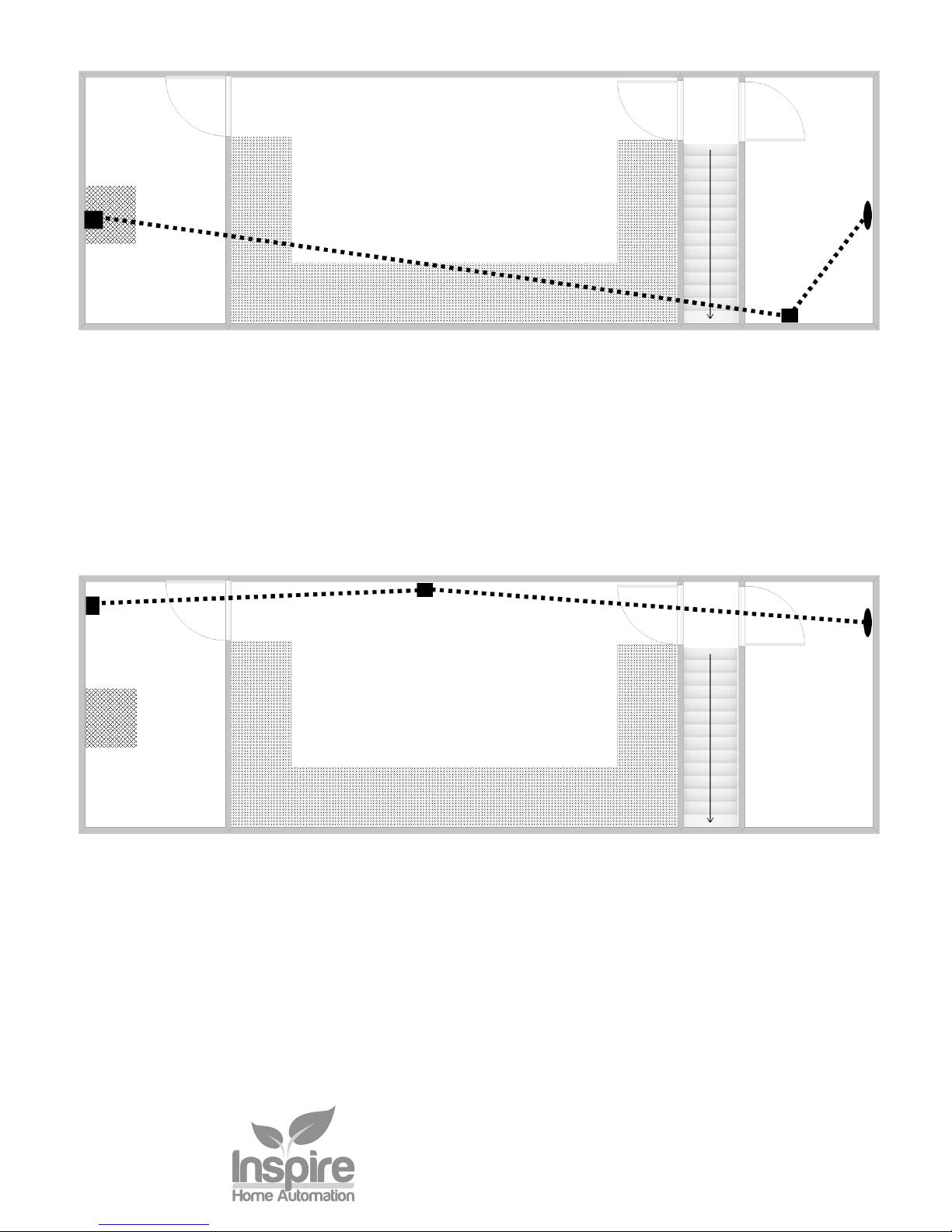
With a few simple changes we have vastly improved the signal.
The Relay Module is positioned away from metal objects.
The Gateway is positioned centrally between the Thermostat and Relay Module.
The Room Thermostat has been positioned to avoid the staircase.
Kitchen
Boiler
Relay
Module
Gateway
Thermostat
Good Positioning
Bad Positioning
Page 4

4
Inspire Home Automation
www.inspirehomeautomation.co.uk
contact@inspirehomeautomation.co.uk
01202 798390
Green Green or
Flashing
Yellow
Green or
Yellow
Plug the Gateway into a spare ethernet port on the router using the supplied cable, then plug the supplied
power adapter into the back of the gateway and plug into a spare power outlet. Allow 30 seconds for the
Gateway to power up. You should see a Green Power Light and a Flashing Amber or Green centre light.
The Radio light may be Amber or Green, depending on whether other units are switched on.
If the Middle light is not on, then the device does not have a valid connection to our Web Servers. Try the
following.
• Move our device to a different port. Some routers only have a single 10Mbps port. Try all the ports,
especially port 1 and port 4.
• Do you have a valid internet connection? Check by plugging in another device.
• Unplug both the Router and the Gateway. Wait 30 seconds, then plug the router back in. Wait 2
minutes, then plug our Gateway back in.
Installation - Gateway
Page 5

Inspire Home Automation
www.inspirehomeautomation.co.uk
contact@inspirehomeautomation.co.uk
01202 798390
5
Tools Required (Not supplied)
Philips screwdriver
Flat blade screwdriver
Long nosed pliers
BS4662 back box
Isolate the existing supply, then remove the existing Programmer (if fitted). Make a careful note of all
wiring locations of the existing programmer before removing any wires. The Relay Module will replace
most existing programmers on the market.
Remove the front cover from the Relay Module, this should easily lift of the unit. If the unit has been
‘clicked’ in place, then grip the recessed part of the rear and pull the chrome part of the front cover off.
Pull out the control panel from the wall mount by placing two fingers
on either side whilst holding the wall mount and pulling apart.
Then secure the wall mount onto the single or double gang back box using the two M3 screws provided.
If you are not using an existing back box then you will either need to
sink a backbox into the wall, or use an external back box. You can
find these in all good hardware stores.
This unit is designed for fixed wiring only. Wire the unit up following the appropriate circuit schematic
for your heating system type, ensuring that all wires are securely held and that no bare copper is visible
outside the connector block. For ease of wiring, we recommend 1mm2 cable, although 1.5mm2 can also
be used. All wiring should conform to the current IEEE wiring regulations. When replacing an existing
programmer, the wiring conversion table, on the back cover, may be of assistance.
All diagrams are in schematic form and earths have been omitted on the drawings for clarity. The NS1002
is a class 2 device and does not require an earth. Ensure that you do not break earth continuity to the
rest of the circuit. You may need to join the existing earth leads together using a terminal strip. Ensure
that the circuit is protected by a 3 amp fuse.
If you are replacing an existing Wired Thermostat with our Wireless Thermostat.
The Wired Thermostat should be removed from the circuit and the Thermostat wiring made safe by
disconnecting the wiring and bridging the connections if required. Depending on your existing system, the
wired Thermostat may be wired back to either your programmer, the wiring centre / junction box, a zone
valve or the boiler itself.
Installation - Relay Module
Page 6

Inspire Home Automation
www.inspirehomeautomation.co.uk
contact@inspirehomeautomation.co.uk
01202 798390
6
fig. 1
fig. 2
Y Plan
S Plan
Combi Boiler
fig. 3 fig. 4
Single Zone Two Zone
Programmer Programmer
Programmer
Programmer
Wiring Diagrams
For guidance please refer to the wiring diagrams below, and/or the Wiring Conversions on the last page.
After the wiring has been completed, Push the control board assembly
into place and secure using the 4 screws. Before putting on the front
cover, we suggest that you test the unit for correct operation.
Page 7

7
Inspire Home Automation
www.inspirehomeautomation.co.uk
contact@inspirehomeautomation.co.uk
01202 798390
Remove the two securing screws on the bottom edge of the thermostat and lift the thermostat off the wall
mount.
The wall mount is supplied with fixings suitable for a solid wall. If you are fixing to another type of wall,
then different fixings may need to be obtained.
Using the wall mount as a template, mark the location of the two holes on the wall. For reference, the two
holes are 75.5 mm apart.
Drill suitable holes (6mm diameter for the wall plugs supplied), insert wall plugs and screw the wall mount
to the wall.
WARNING be aware of any buried cables before drilling.
Install two AA Alkaline batteries (Supplied) into the back of the room thermostat, and ensure that the
display is illuminated.
It is easiest to start the two securing screws off before placing it on the wall, however do ensure that
these screws do not protrude inside the room thermostat.
Carefully locate the room thermostat over the wall mount. The room thermostat should slide over the wall
mount with little effort. If it does not, do not force it, but check the following then try again
° Securing screws do not protrude into the thermostat
° Wall mount screws are the correct size
Hold the room thermostat in place and lightly tighten the screws underneath to secure the unit – these
screws only need the lightest of pressure and must not be over tightened
Installation - Thermostat
Page 8

Inspire Home Automation
www.inspirehomeautomation.co.uk
contact@inspirehomeautomation.co.uk
01202 798390
8
You should have the following.
If there is no RF link displayed on the Thermostat, and it was switched on before the Gateway, it may
take up to 10 minutes to link up. To avoid waiting, ensure the Gateway is plugged in, then reset the
Thermostat by pressing and holding all four buttons for 5 seconds. The unit should reset and connect
within 30 seconds.
Testing the Hot Water
HW. The light should be out. Press the HW button twice to switch it on.
It will light green and the unit will call for heat on the HW circuit. Check that the boiler has fired up and
any zone valves have moved to their appropriate positions. Press the button again to turn the channel off.
Testing the Central Heating
The CH light should be green. On the Thermostat, repeatedly press the ‘S’ key to cycle between the
modes until ‘ON’ is displayed. Then press and hold the ‘+’ key to raise the target temperature several
degrees above the room temperature. eg 25 degrees. The CH light on the Relay module should start
to flash Green. Check that the boiler has fired up and any zone valves have moved to their appropriate
positions. Press the ‘S’ key again on the Thermostat to switch it off.
Once you have ascertained that the unit is functioning correctly, push the front cover over the Relay
Module until it clips into place. Finally remove the protective film from the cover.
Please leave this installation manual with the user.
Testing the system
Green GreenFlashing
Amber or
Green
RF Symbol
Green or
Flashing
Green
Green
Page 9

Inspire Home Automation
www.inspirehomeautomation.co.uk
contact@inspirehomeautomation.co.uk
01202 798390
9
Pairing
Your units were all pre paired before they left the factory. If they do not connect up correctly, and you
have waited for at least 10 minutes, the most likely reason is radio range, see the section on ‘Radio
Signal’ above.
In the unlikely event that you need to pair the units to each other then:
To Pair the Programmer to the Internet Gateway.
• Press the pairing button on the back of the gateway, (The RF light will flash amber)
Press the pairing button twice on the programmer.
To Pair the Thermostat to the Internet Gateway.
• Press the pairing button on the back of the gateway, (The RF light will flash amber)
• Press and hold the M & S keys on the Thermostat for 5 seconds, the RF symbol, bottom left
should start to flash.
To Pair the Thermostat to the programmer (Only possible after both Thermostat and programmer are
connected to the Internet Gateway)
• Press the pairing button on the programmer, this will make all three lights flash. Then press the
appropriate button (CH) to pair the central heating channel to a thermostat, this will start the light
flashing,
• Press and hold the ‘S’ and ‘-’ keys on the Room Thermostat until the RF indicator in the lower left
hand corner starts to flash.
Page 10

Inspire Home Automation
www.inspirehomeautomation.co.uk
contact@inspirehomeautomation.co.uk
01202 798390
10
Wiring Conversions
Table 1
NS1002 Neutral Live HW
OFF
HW ONCH
OFF
CH ONComments
N L 1 2 3 4
DANFOSS RANDALL FP975 N L 3 1 6 4 Only if Terminals L,2,5
are Linked
DANFOSS RANDALL FP715Si N L 1 3 2 4
DANFOSS RANDALL 4033 7 6 5 4 3 2
HORSTMANN 425 DIADEM,
TIAGRA
N L 3 1 6 4 Only if Terminals L,2,5
are Linked
HORSTMANN 425 CORONET N L 6 4 Only if Terminals L,2,5
are Linked
HORSTMANN CHANNELPLUS XL
SERIES 2
N L 3 1 6 4 Only if Terminals L,2,5
are Linked
HONEYWELL ST669 N L 7 6 4 3
HONEYWELL ST6300, ST6400 N L 1 3 2 4
HONEYWELL ST900A, ST900C N L 1 3 2 4
INVENSYS LIFESTYLE LP241,
LP522, LP722
N L 1 3 2 4
POTTERTON EP2000, EP3000 N L 1 3 2 4
RANDALL 702 N L 4 3 2 1
SALUS EP200 N L 1 3 2 4
SMITHS IND. CENTROLLER 1000 N L 1 3 2 4
SWITCHMASTER 800, 805, 900,
9000, 9001
N L 4 3 2 1
Please note: if there is no cable in the above position, then leave this position blank on the relay module.
 Loading...