

Inspire NS1002-1CH Installation Manual
Inspire Home Automation
www.inspirehomeautomation.co.uk
contact@inspirehomeautomation.co.uk
01202 798390
1
NS1002-1ch Installation Guide Rev 1.0
WARNING Electricity is dangerous. Before commencing work, ensure that you read and understand these instructions and isolate
the relevant circuit. This product should only be installed by a qualified electrician or heating engineer and should be installed
in accordance to BS 7671 (IEE Wiring Regulations), or to another equivalent standard.
CAUTION: High Voltage Wires
The NS1002-1ch series is designed to control a typical Combi Boiler setup. It can switch a single output
channel. The central heating channel is switched on and off in response to commands from the supplied
Wireless Thermostat.
The Hot Water channel is not used.
Whats in the box
Introduction
1 x Assembled Room Thermostat consisting of
1 x Room Thermostat
1 x Wall Mount
1 x Assembled Relay Module consisting of
1 x Control Board
1 x Wall Mount
1 X Front Cover
1 x Gateway
1 x Network Cable
1 x Power Supply
1 x Thermostat screw pack
1 x Relay Module Screw Pack
2 x Batteries
Gateway Room Thermostat
Relay Module
Relay Module
Screw Pack
Thermostat
Screw Pack
Batteries Network CablePower Supply

2
Inspire Home Automation
www.inspirehomeautomation.co.uk
contact@inspirehomeautomation.co.uk
01202 798390
Radio Signal
Specifications
Relay Module
Power Supply: 230V~ 50...60Hz, 2.5W (Max)
Switch Type: 1 x SPST
Switch Rating: 3 Amps
Radio Frequency: 2.4 GHz
Dimensions: 160 x 100 x 18 mm (35mm including recessed wallmount)
Room Thermostat
Thermostat Power Supply: 2x AA batteries
Controllable Temperature Range: 10 – 30°C
Frost Protection: Programmable from 0.5 - 30°C
Radio Frequency: 2.4 GHz
Dimensions: 119 x 88 x 22 mm
Gateway
Power input: 5V 1A
Internet Connection: Wired Ethernet Cable
Radio Frequency: 2.4 GHz
Dimensions: 94 x 79 x 24 mm
Consideration for location of your new system components and the affects that this may have on the radio
signal is extremely important. The signal will travel between units in a straight line and will degrade both
with distance and (much more importantly) objects that it has to pass through.
The Relay Module needs to connect to the Wireless Internet Gateway
The Thermostat needs to connect to EITHER the Wireless Internet Gateway OR the Relay Module (It will
automatically select the best signal path)
Every house is different and this is NOT a gaurantee, but as a guide, the units should be able to
communicate with each other through two single skin brick or stud walls.
If the above is not possible, then you may need to consider adding our repeater(s) into the system, or
moving one or more of the system components.
Also, the radio can be adversely affected by large metal objects such as your boiler, radiators and mirrors.
For best performance, ensure that your units are placed at least 1 metre away from such objects.
3
Inspire Home Automation
www.inspirehomeautomation.co.uk
contact@inspirehomeautomation.co.uk
01202 798390
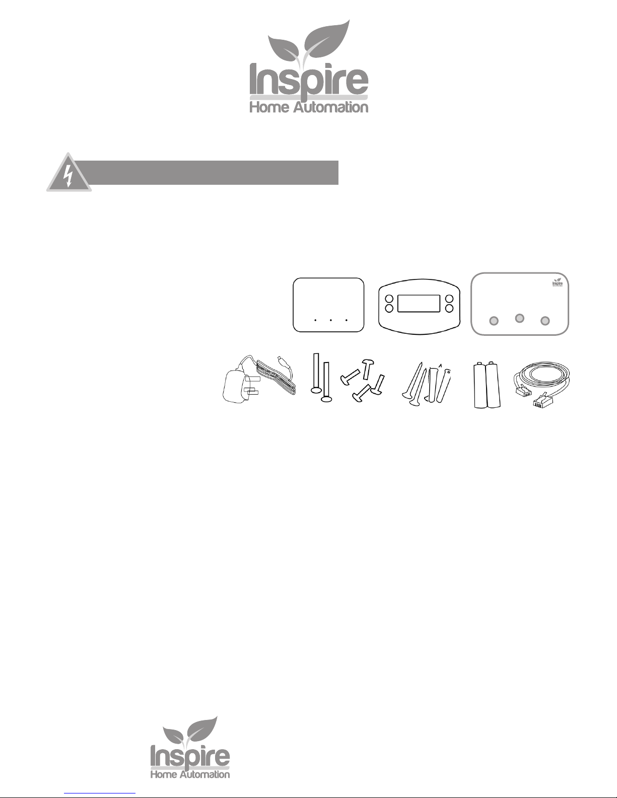
The above image shows the path that the signal will travel to communicate between the 3 units.
This is an example of badly positioned items for the following reasons.
The Relay Module is position under the boiler
The signal between the Relay Module and Gateway needs to travel through three walls, a
staircase and various kitchen objects, including Units, Oven and Fridge.
Kitchen
Boiler
Relay
Module
Gateway
Thermostat
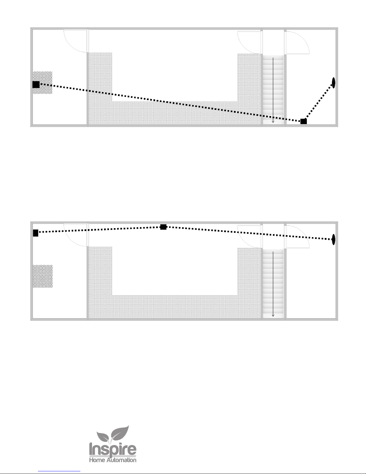
With a few simple changes we have vastly improved the signal.
The Relay Module is positioned away from metal objects.
The Gateway is positioned centrally between the Thermostat and Relay Module.
The Room Thermostat has been positioned to avoid the staircase.
Kitchen
Boiler
Relay
Module
Gateway
Thermostat
Good Positioning
Bad Positioning
 Loading...