

Inspire NS1001 Plus, NS1001 LV Plus Zones, NS1001 HL Zones, NS1001 LV Plus, NS1001 HL Installation & Manuals
...Page 1
2
INSTALLATION & MANUALS
NS1001 Plus
NS1001 LV Plus
NS1001 HL
NS1001 Plus Zones
NS1001 LV Plus Zones
NS1001 HL Zones
Page 2

Inspire Home Automation
www.insiprehomeautomation.co.uk
Installation & User manual
1
Contents
What’s in the box 2
Your Thermostat 3
Your Gateway 4
Setup 4
Pairing and Connecting 4
Status Lights 5
Test your Inspire Thermostat 6
Test the connection 6
Activation 7
Activation code 7
Unit Codes 7
Installing your Thermostat 8
Before you start 8
Preferred place for your Inspire Thermostat. 9
Removal of your old Thermostat 10
Install the wall mount 10
Prepare you new Inspire Thermostat 10
Wiring your Inspire Thermostat 11
Install the Thermostat 12
Using your new Thermostat 12
Basic Functions 13
Adjusting the Temperature 13
Off 13
P1 (Profile 1) 13
P2 (Profile 2) 13
On 13
Menu 13
Setting the clock 14
Boost Mode 14
Program advance 14
Installing additional Thermostats 15
Specification 15
Troubleshooting 16
EC Declaration of Conformity 18
Page 3

2
Inside the box you will find the following
1 x Assembled Room Thermostat consisting of
1 x Room Thermostat
1 x Wall Mount
1 x Wiring Cover
1 x Internet Gateway
1 x Network Cable
1 x Power Supply
2 x AA Batteries
2 x Screws
2 x Wall Plugs
What’s in the box
Inspire Home Automation
www.insiprehomeautomation.co.uk
Installation & User manual 2
Page 4

3
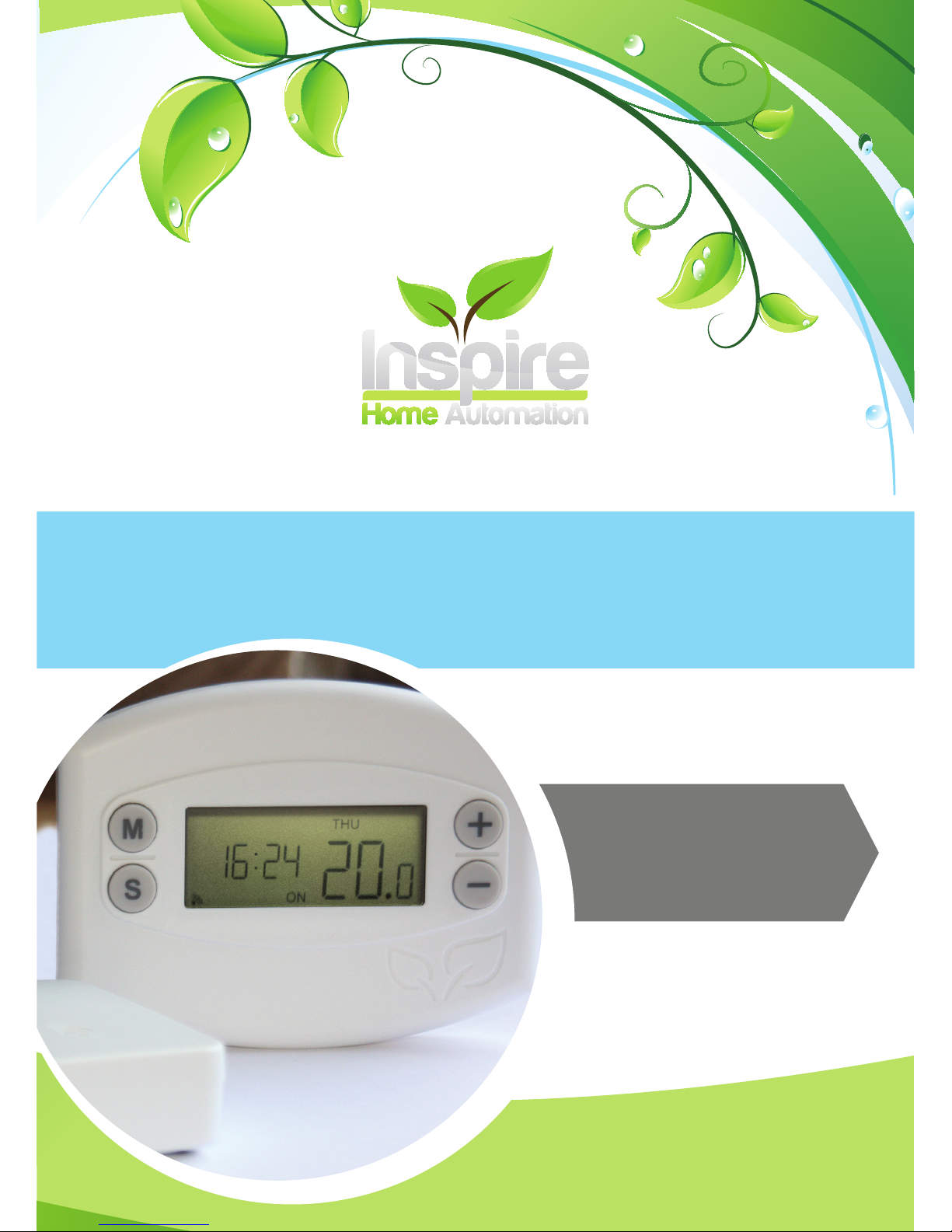
Your Thermostat
Installation & User manual
www.insiprehomeautomation.co.uk
Inspire Home Automation
3
Day
Time
Menu
Select
RF Link
Function
Temperature
Adjustment Keys
Low Battery
Time
Current Time / Program Times.
Current Function
The current selected function.
RF Link
This icon is displayed when the Room Thermostat has a connection to the Internet Gateway.
Low Battery
If this icon displays then it is time to replace the batteries.
Menu / Advance
Enter the programming menu or activate program advance. (PLUS unit only)
Select / Boost
Multipurpose, changes function and cycles menu options. Activates the Boost
function. (PLUS unit only)
Adjustment Keys
Multipurpose, these are used to adjust the desired temperature and
program times.
Day
Current Day / Program Days.
Temperature
Current room temperature / Set temperature.
Page 5

4
Your gateway box connects your Room Thermostat to the Internet. This box should be
left powered on and connected to your router via an Ethernet cable at all times.
Your Room Thermostat will still function without a gateway box, however you will not
be able to control it from our website or from the smartphone app.
Your Gateway
Installation & User manual
www.insiprehomeautomation.co.uk
Inspire Home Automation
4
Internet Gateway
Plug in the supplied power cable and connect to your router via the network cable.
Pairing and Connecting
This is the process by which the Room Thermostat and the Gateway are programmed
to recognise each other. Your new Room Thermostat should already be paired to
your gateway at the factory, so they should automatically recognise each other and
connect.
Power up the gateway and wait until the Power Light is green. Then power up the
Room Thermostat. Within a few seconds, the connection should be established,
confirmed by the Radio symbol on the Room Thermostat and the RF Light on the
Gateway switching to green.
If the gateway was switched on after the Room Thermostat, then it may take up to 10
minutes to establish the connection. If you do not wish to wait this long, reset
the Room Thermostat by pressing and holding all four buttons for 5 seconds.
Upon reset, the connection should be made within a few seconds.
Setup
Page 6
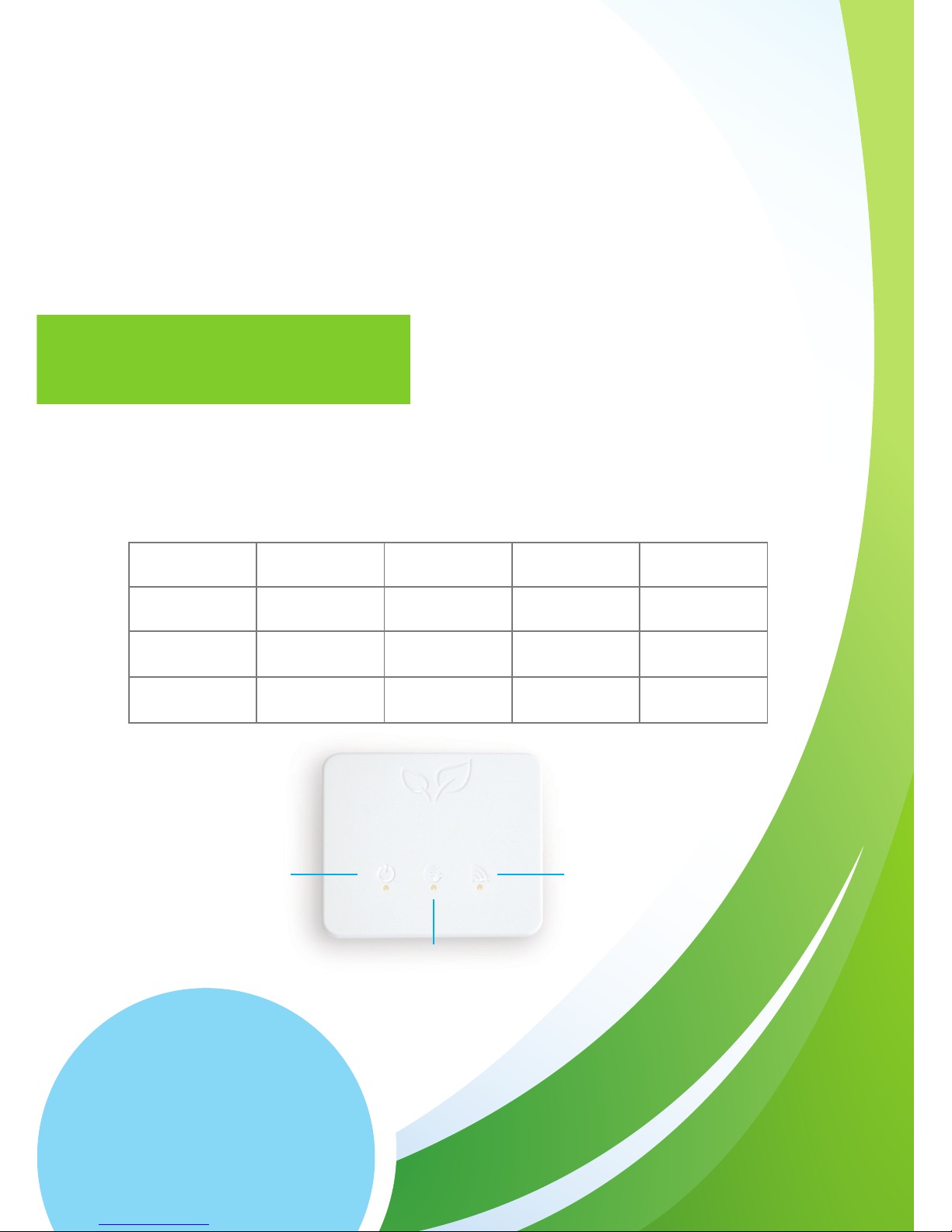
Your Gateway box has multiple status lights for your reference. There are 3
multipurpose lights on your gateway, the Power light on the left, Internet light in the
middle and RF light on the right.
If you have received a replacement unit, an additional unit to create a
Multizone setup, or they will not connect, they will need to be paired.
Switch on both units, wait for the Internet Gateway Power light to go
green, then press the Pairing Button on the back of the Gateway.
The RF Link light will begin to flash Amber.
Next press and hold ‘M’ and ‘S’ simultaneously on the Room thermostat for 5
seconds. This will make a connection icon, located in the bottom left hand corner,
flash. This icon will stay on permanently once a connection has been established.
Power
Internet
RF
Status Lights
Off Flashing amber Amber Green
Power light
No power Initialising Ready
Internet light
No connection Unregistered
Establishing
Connection
Connection
Established
RF Light
No device paired Pairing
Thermostat not
connected
Connection
Established
5
Inspire Home Automation
www.insiprehomeautomation.co.uk
Installation & User manual
Page 7

6
Inspire Home Automation
www.insiprehomeautomation.co.uk
Installation & User manual
Test your Inspire Thermostat
We test all of our products before they leave the factory so let’s make sure it’s arrived
in the same way it left us.
1. Ensure wall mount is still present in the Thermostat.
2. Insert the batteries and check the screen illuminates.
3. Press and hold and raise the temperature to 30 degrees.
4. Press and cycle through the functions until the Thermostat reads ‘ON’. You
should hear the relay ‘click’ on.
5. Press again so ‘OFF’ is displayed, you should hear the relay ‘click’ off.
6. Remove the batteries.
Test the connection
Before you install your new Inspire Thermostat on the wall we recommend you test
the connection between the Thermostat and the Gateway box.
1. Unpack the power supply and plug in the Gateway.
2. Use the supplied Ethernet cable and plug it into the back of the Gateway, connect
the other end to your router.
3. For optimal performance, ensure that your Gateway box is placed minimum 1m
from your router. Do not place the Gateway box on top of your router.
4. Wait until the power light (left hand light) is solid green.
5. Insert your batteries into the Thermostat and place minimum of 1m away from
your Gateway box.
6. Leave the Gateway box and Thermostat to establish a connection. Once
connected the right hand light on the Gateway box will turn green and the RF
Indicator on the Thermostat will show in lower left hand corner.
N.B If your Thermostat was switched on before your Gateway then it could
take up to 10 minutes to connect.
If this an additional Thermostat to add to an existing Inspire
Home Automation system, then you will need to pair the
Thermostat to the Gateway. Please see section on pairing.
Page 8

7
Inspire Home Automation
www.insiprehomeautomation.co.uk
Installation & User manual
Whilst your Gateway box and Thermostat are establishing a connection use this time
to create your online account. We recommend activating your new Thermostat in the
same property as installation.
Visit www.inspirehomeautomation.co.uk/client click the ‘Register’ link and set up your
online account. You will then be asked to validate your account through your email.
Once you have validated your email you will be asked to enter an activation code.
Activation
Once you have activated your online account you will need to
add a device to your account.
If your computer or phone is connected to the same network as
your Gateway box then this should be automatically detected.
If not then you will need to enter a registration code online. You
need to get the this code from your Thermostat.
1. Start by checking your Gateway is in ‘Activation mode’. The
outside two lights will be green and the middle light will be
flashing.
2. Make sure your Thermostat has the symbol in the lower
left corner of the screen.
3. Press and hold and for 5 seconds, 7 dashes will be
displayed, followed by an activation code.
4. Enter this code into the website.
Please note: This activation code is only valid for 1 hour. If it is left longer
you will need to obtain another code from the Thermostat.
Activation code
If the code did not show please try the following:
• Ensure the Gateway box lights are displayed as described above.
• Re-start the process by unplugging your Gateway box, remove
your Thermostat batteries, leave for 5 minutes. Insert the
power cable back into the Gateway and wait for the left hand
power light to become solid green. Insert the batteries into the
Thermostat, leave for 5 minutes and try accessing your activation
code again.
Unit Codes
If you purchased the Landlord
or Holiday Let Model, you
should have been emailed an
activation code to unlock the
extra functionality. Click the
‘Setup’ tab, then scroll down to
‘Unit Codes’ Copy and paste your
activation code here to unlock the
extra features.
If you have purchased a Zoned
Landlord / Holiday Let system,
you should have received a code
for each Thermostat. You will
need to enter one code for each
Thermostat. To switch
Thermostats, click the number in
the top right of web page, then
select a different unit from the
drop down list.
7
Page 9

8
Inspire Home Automation
www.insiprehomeautomation.co.uk
Installation & User manual
Warning Electricity is dangerous. Before commencing work, ensure that you read
and understand the these instructions and isolate the relevant circuits. If in any doubt
whatsoever, do not continue with installation and consult a qualified electrician or
heating engineer.
This unit must be installed in accordance to BS 7671 (IEE Wiring Regulations), or to
another equivalent standard.
Installing your Thermostat
Do I need to install my Inspire Thermostat somewhere new?
We find that most Thermostats are located in rooms that have limited use. The
position of these Thermostats mean the temperature could be warmer or colder than
the homeowners feel. If you need to move your existing Thermostat, contact a trained
electrician to carry out the work before installation or consider our Wireless option.
Before you start
CAUTION: High Voltage Wires
Page 10

9
Inspire Home Automation
www.insiprehomeautomation.co.uk
Installation & User manual
Location is important.
Your Inspire Thermostat needs to communicate efficiently with the Gateway box for
best performance. Radio range is approximately 40 metres in open air, however, this
signal will degrade rapidly for each object that it has to pass through.
• We recommend installing your Inspire Thermostat in a room that is used often.
This will give you an accurate temperature reading and make heating your home
more effective.
• Position - To get the optimum readings place your Inspire Thermostat correctly
using the following:
The homes construction and arrangement may affect the communication so consideration is
needed.
° Place your Inspire Thermostat so you can easily access and read the on screen
display.
° Install on an interior wall.
° Make sure your Thermostat is away from any drafts.
° Install 1.2m - 1.5m from the floor.
° Do not place behind doors or any other objects.
° Place away from radiators.
° Place away from large mirrors
° Do not install in a Kitchen
° There must not be a Thermostatic Radiator Valve (TRV) in the room where the
Thermostat is installed. If there is one present the TRV head should be
removed by unscrewing it from the valve body.
Preferred place for your Inspire Thermostat.
Page 11

10
Inspire Home Automation
www.insiprehomeautomation.co.uk
Installation & User manual
The wall mount comes supplied with fixings for a solid wall. If you are installing on
another type of wall then alternative fixings may be needed. If you are using different
screws, ensure they are pan or round head so when sitting flush they do not protrude
from the Thermostat.
Warning be aware of hidden wires and pipes before drilling.
1. Using the wall mount as a template, position the mount as described in the
‘preferred place for your Thermostat’ section.
2. Insure the wall mount is level and mark the location of the two holes on the
wall. For reference the holes are 75.5mm apart.
3. Drill suitable holes with a 6mm drill bit (for supplied wall plugs) and
insert the wall plugs.
4. Screw the wall mount into place.
Prepare you new Inspire Thermostat
Install the wall mount
1. Ensure that your electrical supply is isolated or switched off.
2. Remove your old thermostat ensuring you make a note of which wires go to which
connections. Please note: the wire colours may not be standard.
3. Tape the wires together to stop them from falling back into the wall and continue
to remove your old Thermostat.
1. Remove the two securing screws from the
bottom edge of the Thermostat and lift the
Thermostat off the wall mount.
2. Remove the Wiring cover from the wall mount
by removing the two securing screws.
Remove screws
Removal of your old Thermostat
Page 12

11
Inspire Home Automation
www.insiprehomeautomation.co.uk
Installation & User manual
Wiring your Inspire Thermostat
Your new Thermostat is a two wire Thermostat. It requires only the Live (L) and the
Switched Live (SL) wire. It does not matter which wire is connected to which terminal.
Note: Great care must be taken to ensure that your room thermostat is wired correctly. Incorrect
wiring can be dangerous and could result in a blown fuse and / or a damaged room thermostat.
Inspire Home Automation will not accept any liability whatsoever for damage caused to your central
heating system and/or electrical system as a result of the incorrect wiring of the thermostat. Also
damage to the thermostat due to incorrect wiring is not covered by your guarantee.
If you are in any doubt whatsoever about the wiring, we strongly recommend that you consult
a qualified electrician or heating engineer.
1. Identify the Live and Switched Live wires.
2. Make all wires that are not used for this installation safe.
3. Prepare the two wires to be connected by striping 5mm off the wire ends.
4. Connect the Live and Switched Live wires to your Inspire Thermostat and tighten
the connector screws.
5. Check the wires are secured in your Thermostat by gently tugging on them. If they
stay in place they are secure.
6. Make sure no bare wire is out of the connector block. If bare wire is showing
remove the wire and cut a small part of the bare wire off. Re-insert and connect
the wire.
7. Fit and screw the wiring cover to the wall mount using the supplied screws.
Important
• Ensure you do not breach the earth continuity of the
circuit.
• Ensure the circuit is protected by a 3 amp fuse.
CAUTION: High Voltage Wires
Page 13

12
Inspire Home Automation
www.insiprehomeautomation.co.uk
Installation & User manual
Install the Thermostat
Using your new Thermostat
Now that your wall mount and wiring is complete, it is time to finish the installation by
mounting your thermostat.
1. Install the supplied batteries into the back of your Thermostat and check the
screen illuminates.
2. Start the securing screws off before placing it onto the wall. This will make it
easier to install. Be sure the screws do not protrude into the Thermostat.
3. Carefully slide your thermostat over the wall mount taking care not to damage
the spring pins at the back. Do not force the Thermostat at this stage, if the
Thermostat does not slide easily check the following:
° Securing screws do not protrude into the Thermostat.
° The wiring cover is correctly installed.
° Wall mount screws are the correct size.
4. Secure the Thermostat by holding in place and lightly tighten the screws
underneath to secure the unit. Do not over tighten.
If you have previously followed the instructions to activate your account then you have
finished installation and your Inspire Thermostat will be ready to use.
1. Make sure your Gateway box is connected and switched on.
2. Using your online account or through the mobile app. Test your thermostat
by setting the preferred temperature and turning your heating to ‘ON’.
3. Your Thermostat should respond within 10-20 seconds.
Congratulations! You’re all done.
If you have not yet activated your account please
see the ‘Activation’ part of this guide.
Page 14

13
Inspire Home Automation
www.insiprehomeautomation.co.uk
Installation & User manual
Adjusting the Temperature
Use the and buttons to set the desired room temperature.
Pressing the key will cycle through the following program functions:
Off
Your heating will be switched off.
P1 (Profile 1)
Your heating will follow the temperature profile
The default is:
15 Degrees between 00:00 and 06:00
20 Degrees between 06:00 and 08.30
17 Degrees between 08:30 and 17:00
22 Degrees between 17:00 and 22:30
15 Degrees between 22:30 and 00:00
P2 (Profile 2)
Your heating will follow the temperature profile
The default is:
16 Degrees between 00:00 and 07:00
20 Degrees between 07:00 and 23.00
16 Degrees between 23:00 and 00:00
On
Your heating will be switched on.
Menu
The Menu button is used to set the clock. However, if you have an Internet
connection this will be done automatically. If you are outside of the
United Kingdom then you can specify your time zone on the ‘Setup’
page within your online account.
Basic Functions
Adjustments &
temperature control
Cycle through functions
Access Menu
Page 15

14
Inspire Home Automation
www.insiprehomeautomation.co.uk
Installation & User manual
Functions continued. . .
Press the button to enter the menu, pressing again will cycle through the
following options (If program advance is enabled, you will need to hold down the
key for 3 seconds to enter the menu.)
To exit the menu press the and buttons simultaneously.
Setting the clock
To set the clock manually Press then use the and keys to set the hours
then press this will take you to the minutes and then the days which are set in a
similar way.
Boost Mode
This is used if you would like to switch your heating on for a set period of time. To use
this feature you need to activate it on our website in the ‘Setup’ section within your
account.
Once activated, the boost function is enabled by pressing and holding the button
for 3 seconds. The ‘ON’ will flash to show that boost is currently active, and it will
switch your heating on for the programmed length of time, at the programmed Boost
Temperature (If set.) After this time has expired, the Thermostat will return to the
previous state.
Program advance
This is used if you would like to ‘jump’ your thermostat to the next profile
temperature. To use this feature you need to activate it on our website in the ‘Setup’
section within your account.
Press the key to ‘jump’ to the next Temperature in your schedule. It will only
have an effect if the Thermostat is in profile mode (P1 or P2).
Pressing the key a 2nd time will cancel the program advance and the
unit will revert back to the set temperature.
Page 16

15
Inspire Home Automation
www.insiprehomeautomation.co.uk
Installation & User manual
If you would like to add additional Thermostats to your account then install the
thermostat as described in the installation guide and then go to your account, select
‘Setup’, scroll down to the additional units section and click ‘Add Device’.
You can also name your units within this section.
Room Thermostat
Thermostat Power Supply 2x AA batteries
Output 2 wire Volt-Free Switch
Switch Rating (Max) 240v ac, 5A.
Controllable Temperature Range 10 – 30C
Frost Protection 5C
Radio Frequency 2.4 GHz
Dimensions 119 x 88 x 22 mm
Gateway
Power input 5V 1A
Internet Connection Wired Ethernet Cable
Radio Frequency 2.4 GHz
Dimensions 94 x 79 x 24 mm
Installing additional Thermostats
Specification
Page 17

16
Inspire Home Automation
www.insiprehomeautomation.co.uk
Installation & User manual
Problem Solution
The Room
Thermostat display is
blank.
Is the unit in power saving mode? (Set via the setup tab on the website)
Pressing a key will bring the display back on for the set period of time.
Unit Malfunction. Reset the unit by pressing and holding all four buttons for 5
seconds.
Batteries exhausted. Replace the batteries.
Battery polarity wrong. Replace batteries noting the correct battery orientation
(Both batteries have positive towards the top of the Room Thermostat)
The Thermostat
Display occasionally
dims.
Incorrect batteries installed. Your Room Thermostat should only be used with
Alkaline batteries. Please note that so called “Heavy Duty” batteries are not
alkaline batteries. Also, NiMH or NiCad rechargeable batteries are not suitable
either.
The room thermostat
does not switch the
central heating
on/off.
Is the thermostat calling for heat? Ensure “ON” is displayed and press the “+”
button to make sure that the temperature set point is higher than the current
room temperature.
Battery very low. If the battery symbol is flashing on the display, the batteries may
be too low to function correctly. Replace the batteries.
Does the relay click on? Ensure the set temperature is higher than the room
temperature, then switch the function to “ON” You should hear an audible click as
the Room Thermostat switches on. Did you hear the click? Yes – The thermostat
is working correctly.
With reference to the installation manual, check the wiring is
secure underneath the wiring cover. Also if your boiler has a
programmer, ensure that the central heating is switched to “ON” If this does not
solve the problem, then the fault may lay in the wiring or the boiler. Contact a
heating engineer.
No – Possible faulty connection between the Room Thermostat and the Wall
Mount. Ensure that screws used are correct, see Installation section. Ensure
that the pads on the wall mount are free grease and fingermarks. Replace the
Thermostat and try to switch on again.
My room thermostat
will not pair, or
repeatedly loses
connection to the
gateway
This is usually caused by interference or distance between the two units.
The connection can be improved by trying the following.
Both units contain a radio aerial. Ensure that there are no metal objects near the
unit.
Do not place the unit on the floor.
Note that your internet router will also most likely contain a radio transmitter
(WiFi) Therefore ensure that your Gateway and internet router are separated.
Move the Gateway closer to your Room Thermostat. This can normally be
achieved by using Home Plugs or a longer network cable.
Troubleshooting
Page 18

17
Inspire Home Automation
www.insiprehomeautomation.co.uk
Installation & User manual
Problem Solution
I cannot connect to
my Thermostat from
my phone / website.
Check the status lights on the gateway box. All three should be green. If the Room
Thermostat or the gateway box has only just been switched on, it can take a few
minutes after all lights go to green, before the website or mobile app will allow a
successful login. If the lights are not all green, then this indicates a problem.
All three lights out: No Power. Ensure power adapter is fully inserted into the
socket and the socket is switched on. Ensure the dc power plug is fully inserted
into the back of the gateway. Does the socket have power? Check by plugging in
another device.
Power light Amber: This should only happen for a short period at power up.
Wait 30 seconds and this light should now be green. If it is not, try resetting the
gateway by removing power, wait 30 seconds, then apply power. This should now
initialise correctly.
Internet Light Amber: Establishing connection with the server. This should shortly
change to green. If there is no Room Thermostat connected, the internet light will
periodically change to Amber, then back to green.
Internet Light out: No connection to the server. This is usually indicative that the
gateway does not have a valid internet connection. Check that the network cable
is securely connected between the gateway and your internet router. Check that
the router/modem is switched on and
connected to your phone line / Internet connection point. Can other devices
such as your pc connect to the internet using a wired cable? Try using all of the
available ports on the rear of the router. (Note BT Homehubs will only work with
some ports)
Internet Light flashing Amber: This is indicative that your gateway Is not
registered with our website. This could also be caused if the Room Thermostat
was inadvertently put into registration mode. Follow the steps in the section
“Registering your Room Thermostat” above to register your system.
RF Link light out: No pairing information. Refer to section “Pairing and
Connecting” to pair your Room Thermostat with your Gateway.
RF Link Light Amber: No connection to the Room Thermostat. Check that the
Room Thermostat is powered up, the low battery indicator is not flashing, and
that the RF Link on the Thermostat is displayed. Check the “My Thermostat will
not pair or repeatedly loses connection” above for information on how to improve
this.
Troubleshooting continued. . .
Page 19

18
Inspire Home Automation
www.insiprehomeautomation.co.uk
Installation & User manual
EC Declaration of Conformity
EC Declaration of Conformity
in accordance with EN ISO 17050-1:2004
We Inspire Home Automation Limited
of 13 Barrow Way, Bournemouth, Dorset, BH8 0HZ
In accordance with the following Directives:
2006/95/EC The Low Voltage Directive
2004/108/EC The Electromagnetic Compatibility Directive
Hereby declare that:
Equipment Internet Room Thermostat
Model number NS1001 (All Variants)
Is in conformity with the applicable requirements of the following documents
Ref. No. Title Edition/date
BS EN 61000-6-1 Electromagnetic compatibility (EMC). Generic 2007
standards. Immunity for residential, commercial
and light-industrial environments
BS EN 60730-1 Automatic electrical controls for household and 2011
similar use. General requirements
I hereby declare that the equipment named above has been designed to comply with the
relevant sections of the above referenced specifications. The unit complies with all
applicable Essential Requirements of the Directives.
Signed:
Name: Gavin Smith
Position: Technical Director
Location: Bournemouth
On: 15 October 2012
 Loading...