

Page 1
M5.2 ASSEMBLY &
OPERATION MANUAL
RECORD SERIAL NUMBER HERE
www.inspirefitness.net by Health In Motion LLC Mar. 2015
Page 2

CONGRATULATIONS…
You’ve just taken the first step to a healthier
and stronger body. This mu lt i-gym by Inspire offers the key to unl ocking
your body’s potential. Regular strength training on a multi-gym has been
shown to deliver a host of benefits including: increased muscle tone,
decreased body fat, improved energy levels, a reduction in stress, and
improved cardiac output. Once again, congratulations, you are on your way
to improving your se lf image, overall health, and quality of life.
BEFORE ASSEMBLING YOUR HOME GYM
IMPORTANT: Read this entire manual before attempting to build or use
this machine. This manual contains step by step instructions for proper
assembly.
Use the parts list included in this manual to verify that all parts are
accounted for before assembly. If any parts are missing, contact the retailer
of this multi-gym for replacement parts. Or, call Inspire at 877-738-1729.
Make sure that adequate room has been cleared before attempting to build
your multi-gym. A rubber mat is recommended for use under your
multi-gym to protect wood flooring or carpeting from damage during
assembly and usage.
This multi-gym is intended for indoor use only. Rust can form on certain
parts including guide rods in a humid environment, resulting in impaired
function.
Service of your multi-gym should only be preformed by an authorized
Inspire retailer. Service preformed by anyone else can result in loss of
warranty. If you need help fin ding an authorized retailer, please contact us
directly:
Inspire Fitness
255 Airport Circle
Suite 101
Corona, CA 92880
Ph: 877-738-1729
Fx: 714-738-1728
www.inspirefitness.net
Page 3

TABLE OF CONTENTS
Section Description……………………………………………………. Page
Important Safety Instructions………………………………………. 1
Tools Required………………………………………………………………… 1
Parts & Hardware List……………………………………………………. 2
Cable Chart ……………………………………………………………………. 3
Assembly Instructions……………………………………………………. 4-23
Decal Reference……………………………………………………………… 24-25
Decal Placement……………………………………………………………… 26
Accessories……………………………………………………………………… 27
General Maintenance Information…….…………………………… 28
Maintenance Schedule…….……………………………………………… 29
Limited Warranty………………………… ………… …… …… ………… …. . 30
Page 4

IMPORTANT SAFETY INSTRUCTIONS
Please read this entire manual and familiarize yourself with all decals and
warnings before using this multi-gym.
• WARNING! It is necessary to inspect this multi-gym regularly to
maintain safety and proper function. Please use the maintenance schedule
included towards the back of this manual. Immediately replace a n y and all
defective or worn parts. Pay special attention to moving parts such as the
cables and pulleys and connections t o accessories. See General
Maintenance section for complete details.
• Use this multi-gym for its intended purpose as described in this Operation
Manual or the exercise chart. Do not use attachments not recommended by
the manufacturer.
• Do not hang from press arm. The press arm is not designed to
support human weight.
• Make sure bystanders are at least 5 feet away from the multi-gym while
it is in use.
• Keep children off the multi-gym at all times.
• Keep the multi-gym away from walls and clear of any obstructions and
furniture.
• Stop immediately if you exper i ence shortness of breath, pain, or dizziness
during your workout. Inspire strongly recommends consulting y ou r
doctor before starting an exercise program.
TOOLS REQUIRED FOR ASSEMBLY
• Metric socket set (including 16mm, 17mm, 18mm, and 19mm sockets)
• Metric 16mm, 17mm, 18mm, and 19mm wrenches
• 4mm, 5mm, and 6mm Hex Keys (supplied in the hardware packs)
• Adjustable wrench
• Tape Measure
• Rubber Mallet
PAGE 1
Page 5

Item
Parts Description Qty
EVS p/n
Item
Parts Description Qty EVS p/n
1 Main Frame, Lat Station 1 57 4 1/2" Pulley 2
2 Main Upright, Press Arm 1 58 Small Pulley, Leg Extension 2
3 Lat Seat Frame 1 59 3 1/2" Pulley 25
4 Seat Base Frame 1 60 Press Arm Exercise Placard 1
5 Preacher Curl Stem 1 61 Cable Ball 4
6 Foot Rest Assembly 1 62 "U" Bracket Cable End 4
7 Seat Stem Assembly 1 63 Floating Pulley Bracket 1
8 Back Pad Mount 1 64 Press Arm Cover Pl ate 1
9 Upper Shroud Mount Bracket 2 65 Lat Exercise Placard 1
10 Double D Low Row Handle Mount 1 66 Press Arm Bearing Assembly 2
11 Lower Pulley M ount 1 67 Rubber Donut 4
12 Press Arm Mount 1 68 Placard Hanger Bracket Assy 4
13 Press Arm Assembly 1 69 Large Plastic Washer 4
14 Back Pad Support Frame 1 70 Weight Plate 40
15 Leg Extension Assembly 1 71 Adjustment Bumper 1
16 Double D Low Row Handle 1 72 Cable Adapter 2
17 Revolving Aluminum Lat Bar 1 73 Corner Bracket 1
18 Revolving Aluminum Curl Bar 1 74 Flat Head Nut, M6 4
19 Calf Block Attachment Arm 1 75 Button Head Bolt, M6*15 4
20 Floating Pulley Bracket Assembly 1 76 Weight Pin Lanyard Assembly 2
21 Adjustable Stop 2 77 Top Weight/Selector Stem Assembly 2
22 Top Beam Plate, Press Arm 2 78 Spring Clip 4
23 Top Beam Plate, Lat Station 2 79 Flat Washer, M8 8
24 Pulley Bracket 1 80 Washer, Φ25.4*Φ10*2 14
25 Barrel Spacer, 1" long 1 81 Locknut, M8 4
26 Lower Guide Rod Mount 2 82 End Cap, Black Plastic 2
27 Cam Plate 1 83 Flat Head Bolt, M10*25 6
28 Floating Pulley Plate 4 84 Button Head Bolt, M5*12 1
29 Swivel Pulley Assy, Lat Station 1 85 Hex Nut, M12 2
30 Calf Raise Block 1 86 Flat Washer, M10 157
31 Shroud Plate Assembly 2 87 Flat Washer, M12 7
32 Shroud Plate 2 88 Curved Washer, M10 4
33 Shroud Bracket 4 89 Thin Locknut, M12, h=8mm 1
34 Preacher Curl Pad 1 90 Locknut, M10 76
35 Seat Pad 3 91 Locknut, M12 3
36 Small Covered Foam Roller 2 92 Button Head Bolt, M8*25 4
37 Thigh Pad 2 93 Hexagon Bolt, M10*100 7
38 Large Covered Foam Roller 4 94 Hexagon Bolt, M10*45 22
39 Covered Foam Roller with tube insert 2 95 Button Head Bolt, M10*20 2
40 Press Arm Lower Cable 1 96 Hexagon Bolt, M10*50 4
41 Leg Extension Cable 1 97 Hexagon Bolt, M10*95 12
42 Press Arm Middle Cable 1 98 Hexagon Bolt, M12*95 2
43 Press Arm Upper Cable 1 99 Hexagon Bolt, M 12*110 1
44 Lat Lower Cable 1 100 Hexagon Bolt, M10*105 3
45 Lat Upper Cable 1 101 Hexagon Bolt, M10*110 1
46 Step Spacer, 1" long 10 102 Hexagon Bolt, M10*70 13
47 Step Spacer, 15mm long 2 103 Flat Head Bolt, M10*70 2
48 Leg Extension Cam Assembly 1 104 Hexagon Bolt, M10*60 4
49 Plastic Spacer Tube 2 105 Hexagon Bolt, M10*35 4
50 Aluminum Endcap 6 106 Hexagon Bolt, M10*20 15
51 Guide Rod 4 107 Hexagon Bolt, M12*150 1
52 Shroud Plate Spacer 2 108 Hexagon Bolt, M10*25 6
53 Shroud Plate Connector Pin 12 109 Flat Head Screw, M6 4
54 Fabric Shroud 2 110 Hex Key Wrench, 6mm 1
55 D Handle Strap 2 111 Hex Key Wrench, 5mm 2
56 Flat washer, M5 1 112 Hex Key Wrench, 4mm 1
113 Thin Locknut, M10,h=8mm 4
Parts & Hardware List
Rev030915
Page 2
Page 6
rev030215
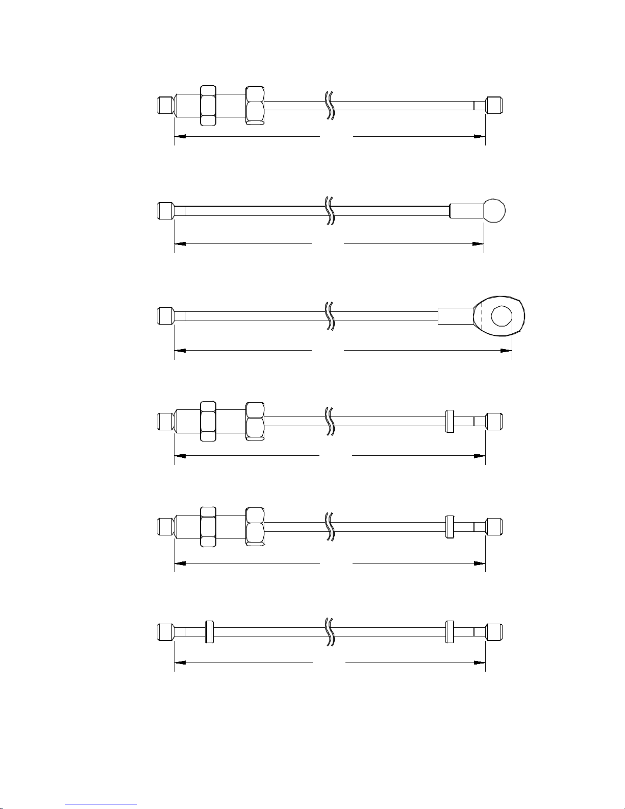
M5 CABLE CHART
Press Arm Upper Cable p/ n G M 870-500-004
Leg Extensi on C able p/n G M 870-500-002
Press Arm Middle Cable p/n GM870-500-003
Lat Upper Cable p/n G M 870-500-006
Cable lengt hs could change at any t im e w it hout not ice.
Lat Lower Cable p/n G M 870-500-005
Cable lengt hs are in m il l im et ers and for reference only.
Press Arm Lower Cable p/ n G M 870-500-001
2681
3386
1905
1885
3576
2886
PAGE 3
Page 7
ASSEMBLY INSTRUCTIONS
PAGE 4
Page 8
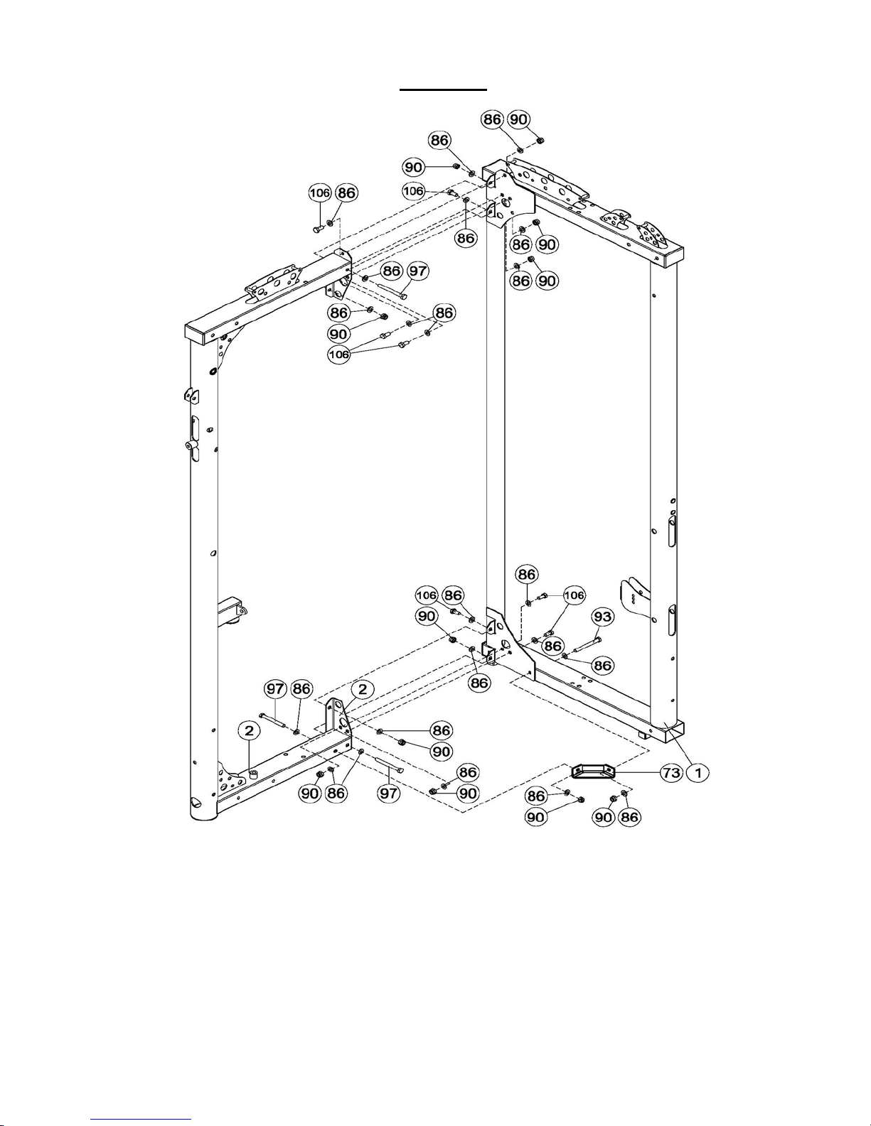
STEP 1
This step requires tw o people to be completed safely
A) Place the Main Frame (1) and the Main Upright (2) as shown and attach them using the
M10*95 bolts (97) and M10*20 bolts (106).
B) Attach the Corner Bracket (73) to the two frames using a M10*95 bolt (97) and M10*100
bolt (93).
Tighten all the hardware at this time.
PAGE 5
Page 9
Calf Block Attachment Arm Flange
A
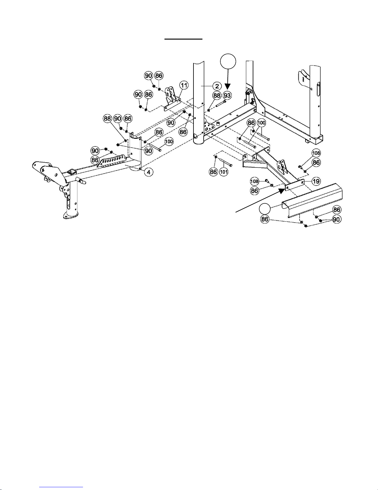
STEP 2
30
Do not tighten any hardware in Step 2 until specifically instructed.
A) Using the M10*100 bolt (93) attach the Seat Base Frame (4) to the Main
Upright (2).
B) Insert the M10*105 bolt (100) above the M10*100 bolt (93) in Step 2A.
C) Attach the Calf Raise Block (30) to the Calf Block Attachment Arm (19) using the M10*25
bolts (108). The flange on the Calf Block Attachment Arm should be positioned on the
inside of the Calf Rai se Block.
D) Attach the Calf Block Attachment Arm (19) and the Lower Pulley Mount (11) to the Main
Upright using the two M10*105 bolts (100) and the M10*110 bolt (101). The slotted
holes in the Calf Raise Block Attachment Arm and Calf Raise Block are to allow up and
down adjustment to ensure the gym is level.
E) Tighten the hardware now by starting with bolt 93 (arrow A). Then tighten the Calf Block
Attachment Arm (19) to the Main Upright (2). Then tighten the Calf Raise Block (30) to
the Calf Raise Block Attachment Arm (19). Tighten all the remaining hardware in
Steps A-D at this time.
PAGE 6
Page 10
1
82
36
102
86
97
90
86
82
36
90
86
102
86
86
86
90
97
86
90
3
6
88
21
STEP 3
A) Attach the Foot Rest Assembly (6) to the Lat Seat Frame (3) using the two M10*70 bolts
(102).
B) Attach the Lat Seat Frame (3) to the Main Frame (1) using two M10*95 bolts (97), four
M10 Flat Washers (86), and two M10 Locknuts (90).
C) Attach the Foot Rest Assembly (6) to the Main Frame (1) using the two M10*95 bolts (97)
with the Curved Washers (88) placed against the round tube upright on the Main Frame.
D) Adjust the Adjustable Stop (21) until it contacts the floor and tighten the Jam Nut.
E) Slide the two Small Covered Foam Rollers (36) onto the Foot Re st and secure wit h the two
black plastic End Caps (82).
Tighten all the hardware in Steps A-D at this time.
PAGE 7
Page 11

Seat Base Frame
4
STEP 4
Selector Plate
A) Attach the bottom of the Back Pad Support Frame (14) to the Selector Plate on the Seat
Base Frame (4).
B) Attach the Back Pad Support Frame (14) to the Main Upright (2) using the M12*110
bolt (99). Tighten this bolt now but ensure that the Back Pad Support Frame can move
easily.
C) Attach the Back Pad Mount (8) to the Back Pad Support Frame (14) using the
M12*95 bolt (98). Tighten this bolt now but ensure that the Back Pad Mount (8)
moves easily.
D) Install the Large Covered Foam Rollers (38) onto the Back Pad Mount. Ensure that the
Large Plastic Washers (69) are plac ed on the Foam Roller tube first then the pad (38),
Aluminum End Cap (50) and then secure this with the M10*25 flat head screws (83).
Tighten now.
PAGE 8
Page 12

STEP 5
95
95
A) Attach the Top Beam Plates (22) to the Main Upright (2) using the two M10*100 bolts
(93) and the smaller M10*20 bolts (106). Only screw in the smaller M10*20 bolts by a
couple of threads to allow the Top Beam Plates to move when inserting the Press Arm
Mount (12).
B) Carefully hang the Press Arm Mount (12) from the Top Beam Plates.
C) Slide the Press Arm Bearing Assemblies (66) onto the shaft of the Press Arm Mount and
attach to the Top Beam Plates using the four M10*20 bolts (106) with the eight smaller
M10 washers (86).
D) Install the two M10*20 button head bolts (95) with the large M10 washers (80) to the
center of the Press Arm Bearing Assemblies.
PAGE 9
Page 13

Pulley 1
86
90
90
92
59
86
92
23
81
94
79
1
79
93
79
86
86
29
23
STEP 6
A) Install the 3.5” Pulley 1 (59) at the top of the Main Frame (1) using the M10*45 bolt (94).
Tighten this bolt now.
B) Install the Top Beam Plates (23), with the Inspire logo to the outside, to the Main Frame
using three of the M10*100 bolts (93). The lower bolt should be inserted into the lower
or back hole at the bottom of the Top Beam Plates. (The upper or forward hole is used for
C) Attach Swivel Pulley (29) to Top Beam Plates (23) using four M8*25 Button Head Bolts
Note: Use the hex key to hold the Button Head Bolts tight while tightening the locknuts.
Tighten all bolts now.
less pre-stretch or for clearance under a lower ceiling.)
(92), eight M8 flat washers (79), and four M8 Locknuts (81).
PAGE 10
Page 14

86
90
86
86
77
70
104
67
105
86
52
113
86
105
102
90
90
102
86
26
2
76
113
31
32
86
51
Front of Weight Plate has a recessed area
for the Weight Plate Number Stickers
Bottom of Weight Plate has three feet
Two holes facing forward
STEP 7
A) Begin by placing the Lower Guide Rod Mount (26) on the Main Upright (2) as shown with
the flanges for bolt (105) towards the front of the gym. Attach the mount using two
M10*70 bolts (102). Tighten the bolts now.
B) Attach the Guide Rods (51) to the Lower Guide Rod Moun t (26) using two M10*35 bolts
(105). Install one bolt from the front and one bolt from the back as shown above. Tighten
the bolts now. Do not allow the Guide Rods to bend the mounting bracket while performing
the next steps.
C) Pl ace the Shroud Plate Spacer (52) on top of the Lower Guide Rod Mount (26). Next p lace
the Shroud Plate (32) on top of the Shroud Plate Spacer (52) and attach with two M10*60
bolts (104). Make sure the two holes in the face of the Shroud Plate face forward. Do not
tighten now.
D) Slide the Rubber Donuts (67) and 20 Weight Plates (70) onto the Guide Rods.
E) Slide the Top Weight/Selector Stem (77) onto the Guide Rods.
F) Now place the Shroud Plate Assembly (31) on the Guide Rods and bolt it to the top of the
Main Upright using two of the M10*70 bolts (102). Tighten this hardware, and Step C
hardware, now. Ensure that all the hardware is tight.
H) Attach the Weight Pin Lanyard Assembly (76) to the end of the Selector Stem sticking out
of the Top Weight Assembly (77). Tighten the two setscrews securely.
PAGE 11
Page 15

113
70
77
51
76
102
86
31
90
86
90
86
1
67
104
86
32
52
86
26
105
113
90
86
102
105
86
86
STEP 8
Repeat the Step 7 instructions to complete Step 8 with the weight stack angled towards the
center of the gym as shown. If installing the LP3 Leg Press, then angle the weight stack towards
the outside of the gym.
PAGE 12
Page 16

Pulley 3
Pulley 4
Pulley 5
Pulley 6
Pulley 8
Pulley 9
Pulley 7
Pulley
10
Press Arm Upper Cable
p/n 870-500-004
STEP 9
Attach pulleys 3 and 4 to the Main Upright (2) as shown with the M10*45 bolts (94). Pulley 5 is
assembled with the Floating Pulley Plates (28) and M10*45 bolts as shown. Pulley 6 is
assembled in the corner of the Main Upright between the Top Beam Plates (22) with the M10*45
bolt as shown. Pulleys 7 and 8 are installed inside the 3” round tube of the Main Upright. Pulley
7 is above Pulley 8 and they are installed with the 1” Step Spacers (46) as shown on both sides
of the tube. Pulleys 9 and 10 are attached to the Press Arm Mount (12) as shown with the
M10*70 bolts (103). Tighten all pulley hardware now.
To route the Upper Cable (43), start by laying it out on the floor to completely unwind it. Then
fully insert the threaded end into the Top Plate of the Weight Stack. With the other end, run the
cable up and over Pulleys 3 and 4 and then down and around Pulley 5 before going back up to
Pulley 6 in the corner of the gym. After routing over Pulley 6 run the cable down through the 3”
tube and around the bottom of Pulley 8 then to the bottom of Pulley 9 in the Press Arm Mount.
Continue back through the 3” round tube to run the cable around the bottom of Pulley 7. Head
back out of the 3” round tube to the bottom of Pulley 10 in th e Press Arm Mount. Go around
Pulley 10 and secure the cable end to the bracket at the top of the 3” round tube as shown using
the M10*45 bolt and the Cable End (55) with Bushing (56) and tighten the hardware.
PAGE 13
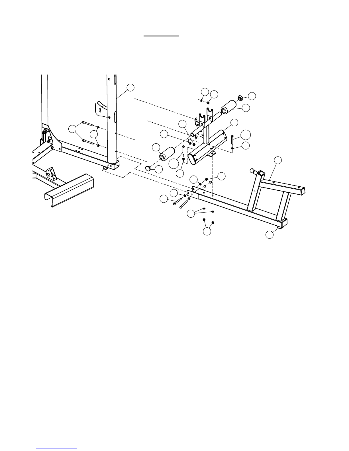
Page 17

Leg Extension
Pulley 11
Pulley 12
Pulley 13
The cable must go over
Lar g e bal l end
STEP 10
89
98
Cable
p/n 870-500-002
this plate or it will be
damaged.
A) Install Pulley 11 and 13 using the M10* 45 bolts (94). Install Pulley 12 using the M10*95
bolt (97) and two 1” Step Spacers (46) as shown in the drawing. Tighten the hardware at
this time.
B) On the Leg Extension Cam Assem b ly (48), remove the four f lat head screws (109) and the
chrome Cam Plate (27). Insert the large ball end of the Leg Extension Cable (41) into the
recessed area and reinstall the chrome Cam Plate with the four screws. Tighten the
screws. Then feed the other cable end between the two small pulleys (58), over the
metal plate and down to Pulley 11 as shown in the enlarged drawing. Run the cable
behind Pulley 11 then down and under Pulley12 and then to the back of the gym. Be sure
the cable goes between Pulley 12 and the cable retainer rod welded inside the tube. You
will finish routing it after Step C.
C) Now insert the Leg Extension Cam Assembly (48) into the Leg Extension Assembly (15)
with the selector number “5” at the top. Now while holding them together, place them
between the two plates of the Seat Base Frame (4) and assemble using the M12*95 bolt
(98), flat washer (87), and thin locknut (89). Tighten this bolt but do not over tighten as
the Leg Extension must be able to rotate freely.
D) Now continue routing the cable by running it through the bottom of the Main Upright (2)
and under Pulley 13. You will finish installing this cable in Step 11A.
PAGE 14
Page 18

Pulley 14
Pulley 15
Pulley 16
Eyelet end
of Cable
STEP 11
Floating Pulley
bottom
Cable Adapter
Press Arm Middle Cable
72
41
20
p/n 870-500-003
Bracket Assembly
has a plate on the
A) Insert the end of the Leg Extension Cable (41), from Step 10, into the Floating Pulley
Bracket Assembly (20) as shown in the circle diagram, slide on the Cable Adapter (72),
seat it in the pulley bracket and install Pulley 14 with M10*45 bolt (94).
B) Now with Press Arm Middle Cable (42), take the end with the eyelet and bolt it to the Main
Frame with M10*25 bolt (108) and tighten the hardware now. Then route the cable under
Pulley 14 through the Floating Pulley Bracket (20) and up the other side of the square
post. The Floating Pulley Bracket and Pulley 14 should now be positioned directly under
the post where the cable end is attached.
C) Attach Pulley 15 to the Floating Pulley Plates (28) with one M10*45 bolt and run the cable
over the top of the pulley and back down towards Pulley 16 (59). At Pulley 16, you will
first need to finish the cable end as in Step A above and then install the pulley into the
Floating Pulley Bracket (63) with one M10*45 bolt.
Tighten all hardware in this Steps A, B, and C above.
PAGE 15
Page 19

Pulley 17
Press Arm Lower Cable
STEP 12
Pulley 18
Pulley 16
78
p/n 870-500-001
A) Install Pulleys 17 and 18 with M10*45 bolts (94) and tighten the hardware.
B) Begin routing the Lower Cable (40) by screwing the threaded end half way into the frame,
near Pulley 17, as shown and tighten the Jam Nut. Then route cable up and around Pulley
16, down around the bottom of Pulley 17 and then under Pulley 18.
C) Remove the hardware from the “U” Bracket (62). Assemble the cable end by sliding one
black Cable Ball (61) on the end of the cable just up to the little R ubber Donut then slide
the cable end into the side of the “U” Bracket. Bolt the Spring Clip (78) to the “U” Bracket
with the hardware. Retighten the “U” Bracket hardware now. Slide the Rubber Donut and
Cable Ball tightly against the “U” Bracket.
PAGE 16
Page 20

Lat Upper Cable
Pulley 22
Pulley 20
Pulley 21
Pulley 23
Pulley 1
Pulley 2
Pulley 24
94
28
90
86
28
59
90
86
86
108
25
86
102
94
86
24
77
STEP 13
Pulley 19
`
p/n 870-500-006
A) Install the Pulley Bracket (24) to the back side of the gym under Pulley 22 with M10*25 bolt (108).
This bolt is installed in the threaded inser t located below Pulley 22 on the back side.
B) Install Pulley 19, 20, 22 and 23 at the top of the Main Frame (1) with the M10*45 bolts (94). Pulley
21 is installed directly below Pulley 22 on the back side of the gym. It is attached to Pulley Bracket
(24) and the gym with the M10*70 bolt (102) and the 1” Barrel Spacer (25) between the pulley and
the Main Frame as shown at the top of the picture.
C) To route the Lat Upper Cable (45), first unwind it by stretching it out on the floor. Then fully screw
the threaded end into the Top Weight Assembly (77) of the weight stack and tighten the Jam Nut.
Route the cable up and around both Pulley 19 and 20 as shown. Be sure to route the cable between
the cable retainer rods and the Pulleys or cable damage will occur.
(NOTE: If you installing an LP3 to the M5.2, go to page 15 in the L P3 manual at this time.)
Continue by routing the cable down and around Pulle y 21 then up and around Pulley 2 2. From there
run the cable over the top of the gym, over Pulleys 20 and 19, then down and around Pulley 23
before running it down to the back side of Pulley 24 . Pulley 24 is assembled with two Floating Pulley
Plates (28) and the M10*45 bolt (94). Run the cable around Pulley 24, then up and over Pulley 1
and 2. Make sure that the cable is routed through the curved opening in the pulley b racket and
between Pulley 2 and the cable retainer pin or the cable will be damaged. Finish the cable end the
same way it was finished in Step 12.
Tighten the hardware for Pulleys 19, 20, 21, 22, 23 and 24 at this time. Also ensure that the
hardware for the Pulley Bracket (24) is tight at the top of the gym.
PAGE 17
Page 21

Pulley 25
Pulley 26
Pulley 27
Pulley 28
Lat Lower Cable
75
78
78
STEP 14
p/n 870-500-005
A) Install 4.5” Pulleys 25 and 28 (57) in the 3” round tube of the Main Frame as shown with
the 1” Step Spacers (46) and M10*95 bolts (97). Install Pulley 26 in the Floating Pulley
Plates (28) with M10*45 bolt (94). Install Pulley 27 in the upper hole in the bracket on
the back side of the 3” round tube of the Main Frame with M10*45 bolt (94).
B) To route the Lat Lower Cable (44), first unwind it by stretching it out on the floor.
Assemble the cable end as in Step 12. This will help to keep the cable from following
through the gym as it is routed. Begin routing with the other end of the cable by running
it under Pulley 25, up and around the front of Pulley 26 in the Pulley Plates (28), down to
the backside of Pulley 27 then under Pulley 28 and out like shown in the diagram.
C) Finish the last Cable End as in the step above.
Make sure that the hardware for Pulleys 25, 26, 27 and 28 are properly tightened.
PAGE 18
Page 22

STEP 15
35
A) Insert the Seat Stem Assembly (7) into the Seat Base Frame (4) as shown. Pull the pop pin out to
allow the seat to lower to a normal height. Then attach the Seat Pad (35) to the Seat Stem
Assembly using the two M10*50 bolts (96) and two M10 Washers (86). Tighten these bolts now
but do not over tighten them or damage can occur. Slide the Thigh Pads (37) onto the Seat Stem
as shown.
B) Install the large Covered Foam Rollers with Tube Inserts (39) onto the lower arms of the Leg
Extension Assembly (15) as shown. Ensure that the Tube Inserts are facing inwards. Secure the
Rollers with the Aluminum Endcaps (50) and the M10* Flat Head Screws (83). Tighten the screws
at this time with the 6mm Hex Key supplied. Next install the other Large Covered Foam Rollers
(38) on to the upper arms of the Leg Extension Assembly by first sliding on the plastic Spacer
Tubes (49), Large Plastic Washers (69) and Rollers (38) on to the arms and secure with the
Aluminum End Caps (50) and M10 Flat Hea d Scre ws (83). Tighten the screws at this time with the
6mm Hex Key.
PAGE 19
Page 23

3
STEP 16
35
35
A) Attach the Seat Pad (35) to the Back Pad Mount (8) using two M10*50 bolts (96) and two
M10 Washers (86). Tighten these bolts now but do not over tighten them or damage can
occur.
B) Attach the Seat Pad (35) to the Lat Seat Frame (3) using the two M10*70 bolts (102) and
two M10 Washers (86). Tighten these bolts but do not over tighten or damage can occur.
C) Attach the Preacher Curl Pad (34) to the Preacher Curl Stem (5) using the two M10*25
bolts (108) and two M10 Washers (86) as shown. Tighten the hardware but do not over
tighten.
PAGE 20
Page 24

64
16
91
13
55
17
87
107
18
10
87
106
8656
84
STEP 17
12
A) Attach the Press Arm Assembly(13) to the Press Arm Moun t (12) using the M12*150 bolt
B) Attach the Double “D” Low Row Handle Mount (10) to the Main Frame Lat (1) using
C) Attach the Curl Bar (18) to the bottom end of the Lat Lower Cable (44) using one Spring
D) Attach two “D” Handle Straps (55) to Press Arm Lower Cable (40) using one Spring Clip.
E) Attach the Lat Bar (17) to the Lat Upper Cable (45) using one Spring Clip.
(107) and wrench tighten now, but make sure the Press Arm can move freely. Attach the
Press Arm Cover Plate (64) to the Press Arm Mount and secure with the M5*12 screw (84)
and the M5 washer (56).
Tighten the screw now.
M10*20 bolts (106) and M10 Washers (86). Attach the Double “D” Low Row Handle (16)
to the upper end of the Lat Lower Cable (44) with the Spring Clip (78).
Clip.
PAGE 21
Page 25

32
53
31
54
53
STEP 18
Shroud Tightening Knobs
While sliding the Shroud Bracket into
33
To install the Fabric Shrouds (54), start by inserting the Shroud Brackets (33) into the pockets
in the Fabric at the top and bottom of the Shroud. For a clean look, the seam or fabric overlap
should be facing inward.
Slide the upper end of the Fabric Shroud, with Shroud Bracket (33) inserted, over the upper
Shroud Plate Assembly (31). Secure the Shroud to the Plate with three Shroud Plate connector
Pins (53).
Slide the lower end of the Fabric Shroud, with Shroud Bracket (33) inserted, over the bottom
Shroud Plate (3 2). Secure the Shroud to the Plate with three Shroud Plate connector Pins (53).
Turn the Shroud Tightening Knobs to tighten the Fabric Shroud and remove any possible
wrinkles.
Repeat this process for the other Shroud.
PAGE 22
the pocket of the Fabric Shroud, align
the rear hole in the Bracket with the
square opening in the rear of the
Shroud.
Page 26

68
60 65
68
STEP 19
A) Attach the front half of the Placard Hanger Brackets (68) to the Lat Exercise
Placard (65) using the two M6*12 Button Head Bolts and two M6 Locknuts.
B) Attach Exercise Placard to Main Frame Upright Tube using the back half of the
Placard Hanger Brackets, four M6*15 Button Head Bolts and four M6 Locknuts.
Do not get the shorter M6*12 mixed with the longer M6*15 bolts. This will cause
assembly pro blems.
C) Repeat Steps A and B for the Press Arm Exercise Placard (60).
DO NOT OVER TIGHTEN THE BOLTS.
PAGE 23
Page 27

877-738-1729
;
DECAL REFERENCE
8,870,718.
PAGE 24
Page 28

DECAL REFERENCE
PAGE 25
Page 29

Back Pad Adjustment
Back Pad Tilt Label
Globe Logo Label
“Inspire M5”
“Do Not Hang From
“WARNING” Label on side
“WARNING,
flats (60 x 40)
Serial number
label (40 x 30)
“Patent” Label
label (50 x 30)
“NOTICE” Label on
Weight # labels
(18 x 25)
“Inspire” logo on both
DECAL PLACEMEN T
(50mm) Round
below logo
label (50 x 38)
Press Arm” below
M5 label (50mm)
Round
of upright. (40 x 170)
PINCH POINTS”
on top of base
tube between LE
sides of the top beam
(127mm x 38mm)
side of upright
(40 x 170)
(1 – 21),
included with
manual. Silver
#’s on black
background.
Label (235 x 20)
(150 x 70)
PAGE 26
placed just below
the “Warning”
Page 30

ACCESSORIES
• Exercise Placards
• Revolving Lat Bar
• Revolving EZ Curl Bar
• Double D Low Row Handle
• D Strap Handles
MULTI-GYM OPTIONS
• Colored Shroud
• Leg Press
• Ab Crunch Bar
Training Tips
CONSULT A PHYSICIAN BEFORE STARTING ANY EXERCISE PROGRAM
1. Always warm up before you start weight training. T h is h elps get
your muscles warm and prevents injury. You can warm up with light
cardio or by doing a light set of each exercise before going to heavier
weights.
2. Control the weight. Always work with a weight that you can handle
through a full range of motion. Slow and steady movements are
recommended.
3. Breathe. Don’t hold your breath during your set. Holding your
breath builds internal pressure which increases your change for broken
blood vessels, as well as a hernia.
4. Sit up straight. Pay attention to your posture and keep everything
straight. Engage your abs in every movement to keep balanced and
protect your spine.
PAGE 27
Page 31

GENERAL MAINTENANCE INFORMATION
• Periodically inspect the cables for splitting, cracking or fraying. Also,
watch for bulging or flat areas on the cable.
• Immediately replace cables at the first signs of damage or wear. Never
use equipment with damaged or worn cables.
• Cables naturally stretch over time, so check cable slack periodically and
adjust cable tension as needed.
• Regularly inspect product for loose hardware.
• Do not use or store equipment outdoors.
• Inspect snap links, swivels, handles, straps, and weight stack pins for
wear or damage. If wear or damage exists, replace immediately.
• Locate and familiarize yourself with all warning decals on the multi-gym.
• Replace damaged or worn upholstery immediately.
• Periodically wipe down guid e r ods with a dry cloth and re-apply a thin coat
of a teflon-based lubricant.
PAGE 28
Page 32

MAINTENANCE SCHEDULE
Inspect: Links, Pull Pins,
Weight Stack Pins
Clean and Lubricate:
based lubricant
ROUTINE
Spring Clips, Swivels,
Clean: Upholstery
Inspect: Cables and
their Fittings
Inspect: Tautness of all
Shrouds
Inspect: Accessory Bars
and Handles
Inspect: All Decals
HOME
MAINTENANCE
WEEKLY
WEEKLY
WEEKLY
WEEKLY
3 MONTHS
3 MONTHS
ENTRY DATE
Inspect: All Nuts and
Bolts. Tighten if Needed
Inspect: Anti-Skid
surfaces
Guide Rods with a Teflon
Lubricate: Seat Sleeves
and all Plastic Slides
Clean and Wax: All
Glossy Finishes
Replace: Cables, Belts
and Connecting Parts
3 MONTHS
3 MONTHS
3 MONTHS
3 MONTHS
YEARLY
2 YEARS
PAGE 29
Page 33

Warranty.
PAGE 30
This Warranty a p plie s to Inspire Strength p r oducts manufactured or distributed by Health In Motion LLC.
CONSUMER USE: LIGHT-COMMERCIAL U SE :
LIMITED LIFETIME FRAME: LIMITED LIFETIME FRAME:
Includes Frame and Welds Includes Frame and Welds
LIMITED LIFETIME PARTS: 10 YEAR PARTS:
Includes Upholstery, Hardware, etc. Includes Upholstery, Hardware, etc.
LIMITED LIFETIME MOVING PAR T S: 10 YEAR MOVING P ARTS:
Includes Pulleys, Cables, etc. Includes Pulleys, Cables, etc.
PLEASE NOTE THAT NOT ALL INSPIR E PRO DUCTS ARE MADE F O R LIGHT-COMMERCIAL USE
Refer to your Owner’s Manual or consult with y ou fitness product dealer to establish if a Product is made for lightcommercial use or not. Using a non-commercial product in a commercial setting can result in s er ious injury or death!
Health In Motion w a r rants that the Product you have purcha s ed for light-commerc ia l, personal, family or household
use from Health In Motion LLC or from an authorized Health I n Motion reseller is f ree from defects in m a terials or
workmanship under nor mal us e during the warranty period. You r s a les r ec eipt, showing the date of purc has e of the
Product, is you r proof of the date of purchase. This warran ty extends only to you, the original pur c haser. It is not
transferable to anyone w ho subsequently purchases the P roduct from you. It excludes expenda ble pa r ts such as paint
and finish. This Warranty becomes VALID ONLY if the Produ c t is assembled / installed according to th e instructions /
directions included with the Product.
Replacement and repair of parts.
During the warranty period Health In Motion will, at no add itional charge, re pa ir or replace the Prod uct if it becomes
defective, malfunctions, or other wise fails to conform with this Warr an ty under normal light-commercial, personal,
family, or hou s ehold use. In repairing the product Health In Motion may replace defective parts with, at the option of
Health In Motion, s erviceable used parts that are equivalent to new parts in performance, or new parts. All exchanged
parts and Produc ts replaced under this warranty will become the property of Health In Motion. H ealth In Motion
reserves the righ t to c hange manuf a cturers and or specifica tion of any part to c over any existing warranty.
Service procedures.
To obtain warran ty parts, you must r eturn the parts to Health I n Motion or an authorized Health In Motion retailer in
its original container (or equivalent). You must pre-pay any shipping charges, taxes, or any other charges associated
with transportation of the Produc t. In addition, you are r esponsible for insuring any Product shipped or returned. Y ou
assume the risk of loss during shipment. You must present Health In Motion with proof-of-purchase documents
(including the date of purchase, Model, and Serial Number ) . Any evidence of alteration, eras ing or forgery of proof of-purchase doc uments will be caus e to void this Warranty. Register your warranty online v is it www.inspirefitness.net
Conditions and Exceptions.
This Warranty doe s not extend to any Pr od uct not purchased f r om Health In Motion LLC or from an authorized He a lth
In Motion reseller. This Warra nty does not extend to any Produ c t th a t h a s been da m a ged or r endered defective; (a)
as a result of accident, misuse, or abuse; (b) by the use of parts not manufactured or sold by Health In Motion; (c) by
modification of the Product; (d) as a result of service b y anyone other th an Health In Motion, or an au thorized Health
In Motion warranty service provider; (e) product that has not been proper ly maintained (follow m aintenance schedule
found on produc t). Should any product submitted for Warra nty service be found to be ineligible, an estimate of repair
cost will be furnished and th e r epa ir will be made if requested by you upon Health In Motion receipt of payment or
acceptable arrangement of payment.
Disclaimer
EXCEPT AS EXPRESSLY SET FORTH IN THIS WARRANTY HEALTH IN MOTION MAKES NO OTHER WARRANTIES;
EXPRESSED OR IMPLIED INCLUDING ANY IMPLIED WARRANTIES OF MERCHANTABILITY AND FITNESS FOR A
PARTICULAR PURPOSE. HEALTH IN MOTION EXPRESSLY DISCLAIMS ALL WARRANTIES NOT STATED IN THIS
WARRANTY. ANY IMPLIED WARRANTIES THAT MAY BE IMPOSED BY LAW ARE LIMITED TO THE TERMS OF THIS
WARRANTY. NEITHER HEALTH IN MOTION NOR ANY OF ITS AFFILIATES SHALL BE RESPONSIBLE FOR INCIDENTAL
OR CONSEQUENTIAL DAMAGES. HEALTH IN MOTION IS NOT RESPOSIBLE FOR THE REPAIR OR REPLACEMENT OF
ANY PARTS THAT HEALTH IN MOTION DETERMINES HAVE BEEN SUBJECTED AFTER THE DATE OF MANUFACTURE TO
ALTERATION, NEGLECT, ABUSE, MISUSE, NORMAL WEAR & TEAR, ACCIDENT, DAMAGE DURING TRANSIT OR
INSTALLATION, FIRE, FLOOD, OR ANY ACT OF GOD. SOME STATES DO NOT ALLOW LIMITATIONS ON HOW LONG AN
IMPLIED WARRANTY LASTS OR THE EXCLUSION OR LIMITATION OF INCIDENTAL OR CONSEQUENTIAL DAMAGES, SO
THE ABOVE LIMITATIONS OR EXCLUSION MAY NOT APPLY TO YOU. This Warranty gives you specific legal rights and
you may also hav e other rights that may vary from state to state. This is the only expr e s s warranty applica b le to
Health In Motion’s “Inspire” bra nded strength produc ts . Health In Motion n e ither assumes nor au thorizes anyone to
assume for it any other express warranty.
 Loading...