

Page 1

ASSEMBLY & OPERATION MANUAL
RECORD SERIAL NUMBER HERE
by Health In Motion LLC
Nov. 2014www.inspirefitness.net
Page 2

CONGRATULATIONS… You’ve just taken the first step to a healthier
and stronger body. This home gym by Inspire Fitness offers the key to
unlocking your body’s potential. Regular strength training on a home gym
has been shown to deliver a host of benefits including: increased muscle
tone, decreased body fat, improved energy levels, a reducti on in stress, and
improved cardiac output. Once again, congratulations, you are on your way
to improving your self image, overall health and quality of life.
BEFORE ASSEMBLING YOUR HOME GYM
CAUTION: Two people are required to complete steps 1-4 to ensure that
the frame does not fall resulting in injury to the person assembling the
gym.
IMPORTANT: Read this entire manual before attempting to build or use
this machine. This manual contains step by step instructions for proper
assembly.
Use the parts list included in this manual to verify that all parts are
accounted for before assembly. If any parts are missing, contact the retailer
of this home gym for replacement parts. Or, call Inspire Fitness at
714-738-1729.
Make sure that adequate room has been cleared before attempting to build
your home gym. A rubber mat is recommended for use under your home
gym to protect wood flooring or carpeting from damage during assembly
and usage.
This home gym is intended for indoor use only. In addition, garages and
screened in porches are not recommended due to high humidity or dust.
Certain parts including guide rods can form rust in a humid environment,
resulting in impaired function.
Service of your home gym should only be preformed by an authorized
Inspire Fitness retailer. Service preformed by anyone else can result in loss
of warranty. If you need help finding an authorized retailer, please contact
us directly:
Inspire Fitness
4945 E. Hunter Ave.
Anaheim, CA 92807
Ph: 714-738-1729
Fx: 714-738-1728
www.inspirefitness.net
Page 3

TABLE OF CONTENTS
Section Description……………………………………………………. Page
Important Safety Instructions………………………………………. 1
Parts List…………………………………………………………………………. 2
Assembly Instructions……………………………………………………. 4
Decal Reference……………………………………………………………… 22
Decal Placement……………………………………………………………… 24
Accessories……………………………………………………………………… 25
General Maintenance Information…….…………………………… 26
Maintenance Schedule…….……………………………………………… 27
Limited Warranty…………………………………………………………….. 28
Page 4

IMPORTANT SAFETY INSTRUCTIONS
Please read this entire manual and familiarize yourself with all decals and
warnings before using this home gym.
• WARNING! It is necessary to inspect this home gym regularly to
maintain safety and proper function. Please use the maintenance schedule
included towards the back of this manual. Immediately replace any and all
defective or worn parts. Pay special attention to moving parts such as the
cables and pulleys and connections to accessories. See General
Maintenance section for complete details.
• Use this home gym for its intended purpose as described in this Operation
Manual or the exercise chart. Do not use attachments not recommended by
the manufacturer.
• Make sure bystanders are at least 5 feet away from the home gym while
it is in use.
• Keep children off the home gym at all times.
• Keep the home gym away from walls and clear of any obstructions and
furniture.
• Stop immediately if you experience shortness of breath, pain, or dizziness
during your workout. Inspire Fitness strongly recommends consulting your
doctor before starting an exercise program.
TOOLS REQUIRED FOR ASSEMBLY
• Standard socket set (including 13mm, 16mm & 17mm sockets)
• 13mm wrench
• 16mm wrench
• 17mm wrench
• 19mm wrench
• Tape Measure
• Rubber Mallet
• Adjustable wrench
• 5mm Allen wrench – supplied
• 6mm Allen wrench – supplied
Page 1
Page 5

PARTS & HARDWARE LIST
Item Part NO. Parts Description Qty Item Part NO. Parts Description Qty
1 GM875-100-001PZ Main Base 1 44 0111-010-208 Bolt, M10 x 20mm L 8
2 GM872-300-005 Bottom Shroud Plate 1 45 0111-010-258 Bolt, M10 x 25mm L 2
3 GM695-381-001 Guide Rod 2 46 0111-010-403 Bolt, M10 x 40mm L 2
4 GM692-501-003PZ Selector Stem / Top Weight 1 47 0111-010-458 Bolt, M10 x 45mm L 2
5 W5 Weight Plate 20 48 0111-010-508 Bolt, M10 x 50mm L 4
6 GM692-881-003 Rubber Donut 2 49 0111-010-558 Bolt, M10 x 55mm L 2
7 GM692-380-001 Weight Stack Riser 2 50 0111-010-758 Bolt, M10 x 75mm L 2
8 GM692-500-002PZ Adjustable Pulley 1 51 0111-010-858 Bolt, M10 x 85mm L 4
9 0110-412-02 Hex Flange Nut 1 52 0111-010-908 Bolt, M10 x 90mm L 2
10 GM692-500-004PZ Weight Selector Pin 1 53 0111-110-058 Bolt, M10 x 110mm L 2
11 GM875-230-001PZ Main Upright 1 54 0111-010-125 Bolt, M10 x 125mm L 2
12 GM875-110-001 Rear Base 1 55 0111-010-218 Bolt, M10 x 205mm L 4
13 GM875-280-001 Base Brace, L 1 56 0113-210-258 Bolt, M10 x 25mm L (Flat Head) 7
14 GM875-290-001 Base Brace, R 1 57 0113-210-758 Bolt, M10 x 75mm L (Button Head) 1
15 GM875-200-001PZ Upright Support 2 58 0113-208-258 Bolt, M8 x 25mm L (Button Head) 8
16 GM875-240-001PZ Top Beam Assembly 1
17 GM875-340-001 Top Shroud Plate 1 60 GM695-561-015 Bolt, M12 x 65mm L 6
18 GM875-210-001 Center Upright Brace 1 61 0116-012-008 M12 Flat Washer 6
19 GM875-220-001 Upper Swivel Pulley Bracket 2 62 0116-010-008 M10 Flat Washer 70
20 GM875-260-001PZ Center Pulley Assembly 1 63 0116-008-028 M8 Flat Washer 16
21 GM875-270-001PZ Rear Upper Pulley Assembly 1 64 0110-712-008 M12 Lock Nut 6
22 GM695-320-012PZ Swivel Pulley 6 65 0110-710-008 M10 Lock Nut 29
23 GM875-300-001PZ Seat Frame 1 66 0110-708-028 M8 Lock Nut 8
24 GM875-320-001PZ Linkage Bar 3 67 0113-710-458 Bolt, M10 x 45mm L 2
25 GM875-330-001PZ Linkage Bar, Pin 1 68 0111-010-018A M10 x 100mm L 2
26 GM875-310-001 Back Pad Mount 1 69 0110-010-108 M10 Lock Nut 2
27 GM875-400-001 Seat Pad 1 70 6mm Wrench 1
28 GM875-400-002 Back Pad 1
29 SHC2 Shroud 1
30 GM660-820-001 Short D-Handle 4
31 GM875-351-001PZ Floating Pulley Assembly 2
32 GM872-381-005 Shroud Bracket 2
33 GM872-561-004 T Pins 6
34 GM880-101-016 Cable "U" Bracket 6
35 0200-070-082 Spring Clip 6
36 0113-206-138A M6 x 12 Button Head Bolt 6
37 GM880-201-032 M6 T-Nut 6
38 GM851-881-009 Plastic Ball 6
39 GM875-500-001 Upper Cable Assembly 1
40 GM875-500-002 Lower Cable Assembly 2
41 GM692-880-001 3 1/2" Pulley 2
42 GM870-880-001 4 1/2" Pulley 2
43 Multi "D" Ring Handle 2
Page 2
Page 6

CABLE CHART
LP3 MAIN CABLE
GM872-500-005
UPPER CABLE (5,920mm)
GM875-500-001
LP3-M5 CABLE
GM872-500-006
MIDDLE CABLE (4,670mm)
GM875-500-002
Page 3
Page 7
2-M10x50 Hex Bolts
4-M10 Flat Washers
2-M10 Lock Nuts
42
11
2-M10x40 Hex Bolts
2-M10 Flat Washers
1
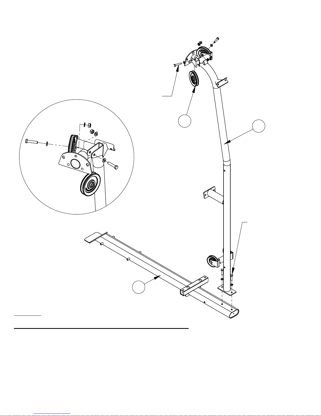
Step 1
DO NOT TIGHTEN ANY HARDWARE IN THIS STEP
Attach the Main Upright (11) to the Main Base (1) using 2- M10x40 Hex bolts (46) and A
2- M10 Washers (62).
Attach 2- 4-1/2” Pulleys (42) to the Main Upright (11) using 2- M10x50 Hex bolts B
(48), 4- M10 Washers (62), and 2- M10 Lock Nuts (65).
PAGE 4
Page 8
12
1-M10x75 Hex Bolts
2-M10 Flat Washers
1-M10 Lock Nut
11
Step 2
DO NOT TIGHTEN ANY HARDWARE IN THIS STEP
Attach the Rear Base (12) to the Main Upright (11) using 1- M10x75 Hex bolts (50), A
2- M10 Washers (62), and 1- M10 Lock Nuts (65).
PAGE 5
Page 9
30
13
14
2-M10x110 Hex Bolts
4-M10 Flat Washers
2-M10 Lock Nut
12
13
Step 3
DO NOT TIGHTEN ANY HARDWARE IN THIS STEP
Attach the Left Base Brace (13) and Right Base Brace (14) using a M10x125 Hex Bolt A
(54), 2- M10 Washers (62), and 1- M10 Lock Nut (65).
Attach a 3-1/2” Pulley (41) to both sides of the Rear Base (12) using 2- M10x110 Hex B
bolts (53), 4- M10 Washers (62), and 2- M10 Lock Nuts (65).
31
1-M10x125 Hex Bolts
2-M10 Flat Washers
1-M10 Lock Nut
PAGE 6
Page 10
8-M10x20 Hex Bolts
8-M10 Flat Washers
12
15
15
Step 4
DO NOT TIGHTEN ANY HARDWARE IN THIS STEP
Insert the Upright Supports (15) to the Rear Base (12) using 8- M10x20 Hex bolts A
(44) and 8- M10 Washers (62).
PAGE 7
Page 11

4-M10x85 Hex Bolts
8-M10 Flat Washers
4-M10 Lock Nuts
1-M10x75 Hex Bolts
2-M10 Flat Washers
1-M10 Lock Nut
11
15
18
Step 5
DO NOT TIGHTEN ANY HARDWARE IN THIS STEP
Attach the Center Upright Brace (18) to the Main Upright (11) using 1- M10x75 A
Hex bolts (50), 2- M10 Washers (62), and 1- M10 Lock Nuts (65). Then attach
the Center Upright Brace (18) to the Upright Supports (15) using 4- M10x85 Hex
bolts (51), 8- M10 Washers (62), and 4- M10 Lock Nuts (65).
PAGE 8
Page 12

3
2-M10x55 Hex Bolts
4-M10 Flat Washers
2-M10 Lock Nuts
2
1
Step 6
DO NOT TIGHTEN ANY HARDWARE IN THIS STEP
2-M10x45 Socket Head Screw
4-M10 Flat Washers
2-M10 Lock Nuts
Attach Guide Rods (3) to the Main Base (1) using 2- M10x45 Sock Head Screws A
(XX), 4- M10 Washers (62), and 2- M10 Lock Nuts (65).
Slide the Bottom Shroud Plate (2) onto the Guide Rods (3) and use 2- M10x55 B
Hex bolts (49), 4- M10 Washers (62), and 2- M10 Lock Nuts (65) to secure the
shroud plate.
NOTE: Verify that the 2 pin holes at the front of the Bottom Shroud Plate (2) are
facing the front of the machine and that the single hole is facing the back of the unit.
PAGE 9
Page 13

17
8
9
4
5
3
6
7
10
Step 7
DO NOT TIGHTEN ANY HARDWARE IN THIS STEP
Slide the Weight Stack Risers (7), Rubber Donuts (6), and 15 Weight Plates (5) onto A
the Guide Rods (3). Make sure the weight sticker cut out is facing the front of the
machine. If a 200 lb stack will be used then the Weight Stack Risers (7) must be
removed.
Screw the Top Weight Pulley Bracket Assembly (8) onto the Selector Stem at the Top B
Weight (4). Thread all the way down but do not tighten yet. Slide the Top Weight
Assembly (4) onto the Guide Rods (3) so the 3-1/2” pulley is positioned between the
two Guide Rods (3).
Insert a Weight Pin (10) into the stack.C
Attach weight stack stickers.D
NOTE: Verify that the 2 pin holes at the front of the Top Shroud Plate (17) are facing the
front of the machine and that the single hole is facing the back of the unit.
PAGE 10
Page 14

19
8-M8x25 Hex Bolts
16-M8 Flat Washers
8-M8 Lock Nuts
15
15
Step 8
DO NOT TIGHTEN ANY HARDWARE IN THIS STEP
Attach the Upper Swivel Pulley Bracket (19) to the Upright Supports (15) using 8- A
M8x25 Button Head Bolts (58), 16- M8 Washers (63), and 8- M8 Lock Nuts (66).
NOTE: It may be necessary to tighten some of the bolts in order to install the rest of the
bolts. If any bolts are tightened down they must be loosened before proceeding to the
next step.
PAGE 11
Page 15

3-M8x25 Flat-Head Bolts
3-M8 Flat Washers
3-M8 Lock Nuts
16
11
19
1-M10x75 Button Head Bolt
1-M10 Flat Washer
Step 9
DO NOT TIGHTEN ANY HARDWARE IN THIS STEP
Attach the Top Beam Assembly (16) to the Upper Swivel Pulley Bracket (19) using a A
M10x75 Button Head Bolt (57) and a M10 Flat Washer (62).
Slip in the Top Beam Assembly (16) onto the Main Upright (11) using 3- M10x25 Flat B
Head Bolts (56), 6- M10 Washers (62), and 3- M10 Lock Nuts (65). The Flat Head
Bolts (56) must be inserted from back of the unit to the front.
Bolt the top of the Guide Rods (3) to the Main Upright (11) and Top Beam C
Assembly(16) using 2- M10x45 Hex bolts (47), 4- M10 Washers (62), and 2- M10
Lock Nuts (65).
PAGE 12
Page 16

20
21
2-M10x50 Hex Bolts
4-M10 Flat Washers
2-M10 Lock Nuts
11
2-M10x25 Hex Bolts
4-M10 Flat Washers
2-M10 Lock Nuts
Step 10
Attach the Rear Upper Pulley Assembly (21) to the Main Upright (11) using 2- A
M10x50 Hex Bolts (48), 4- M10 Washers (62), and 2- M10 Lock Nuts (65).
Attach the Center Pulley Assembly (20) to the Main Upright (11) using 2- B
M10x25 Hex bolts (45), 4- M10 Washers (62), and 2- M10 Lock Nuts (65).
Tighten all hardware from steps 1-10 now.
PAGE 13
Page 17

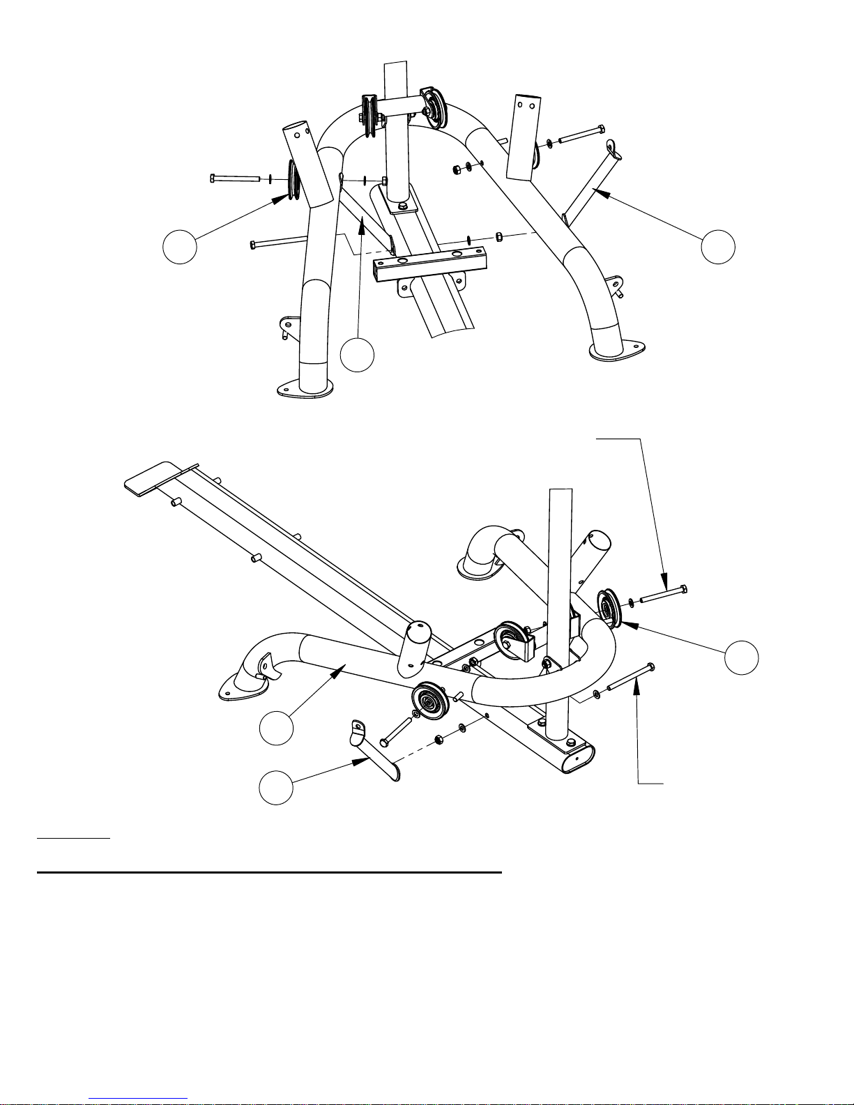
22
18
22
12
22
Step 11
Attach 2 Swivel Pulleys (22) to the Upper Swivel Pulley Bracket (19) using 2- A
M12x65 Hex bolts (60), 1- M12 Washers (61), and 2- M12 Lock Nuts (64).
Attach 2 Swivel Pulleys (22) to the Center Upright Base (18) using 2- M12x65 B
Hex bolts (60), 1- M12 Washers (61), and 2- M12 Lock Nuts (64).
Attach 2 Swivel Pulleys (22) to the Rear Base (12) using 2- M12x65 Hex bolts C
(60), 1- M12 Washers (61), and 2- M12 Lock Nuts (64).
NOTE: The M12 bolts must be installed in the direction shown in the above
drawing such that the head of the bolt faces the back of the unit.
Tighten hardware now.
PAGE 14
Page 18

25
23
24
1
4-M10x205 Hex Bolts
8-M10 Flat Washers
4-M10 Lock Nuts
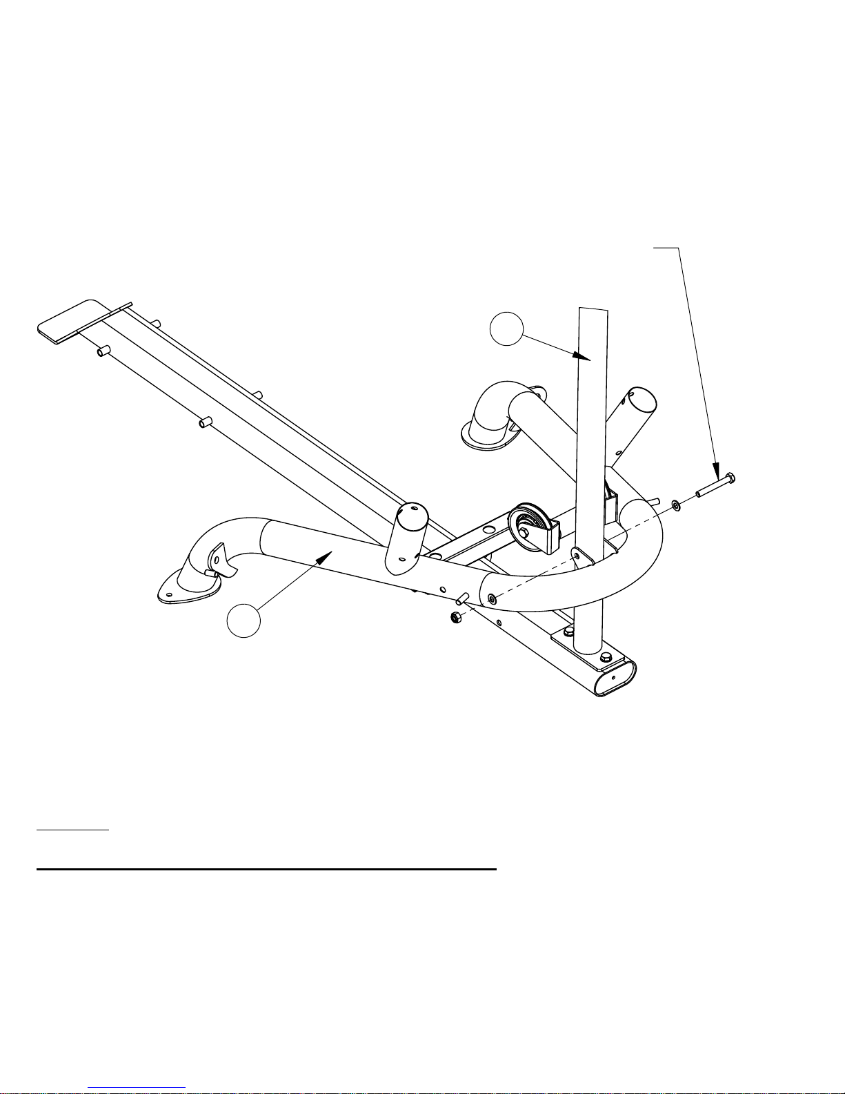
Step 12
Attach Pinned Linkage Bar (25) to the front, left side of the Main Base (1) using 1- A
M10x205 Hex bolts (55) and 1- M10 Washers (62).
Attach 3 Linkage Bars (24) to the Main Base (1) using 1- M10x205 Hex bolt (55), 3- B
M10 Washers (62), and 3- M10 Lock Nuts (65).
Attach the Seat Frame (23) to the Linkages (24, 25) using 2- M10x205 Hex bolts C
(55), 4- M10 Washers (62), and 2- M10 Lock Nuts (65).
Tighten all 4 screws securely then loosen the nuts by ½ a turn. If the seat is binding and
too difficult to adjust then it may be necessary to loosen the nuts more. However, the bolts
must not be too loose.
PAGE 15
Page 19

1-M10x125 Hex Bolts
2-M10 Flat Washers
1-M10 Lock Nuts
23 26
Step 13
Attach the Back Pad Mount (26) to the Seat Frame (23) using 1- M10x125 Hex bolt A
(54), 2- M10 Washers (62), and 1- M10 Lock Nut (65).
Do not over tighten the hardware in this step.
PAGE 16
Page 20

27
23
28
26
4-M10x25
Flat Head Screws
2-M10x90 Hex Bolts
2-M10 Flat Washers
Step 14
Attach the Seat Pad (27) to the Seat Frame (23) using 2- M10x90 Hex bolts (52) and A
2- M10 Washers (62).
Attach the Back Pad (28) to the Back Pad Mount (26) using 4- M10x25 Flat Head Bolts B
(56).
Tighten hardware now.
PAGE 17
Page 21

2-Plastic Balls
2-Cable "U" Brackets
2-M6x12 Button Head Bolts
2-M6 T-Nuts
2-Spring Clips
22
Upper Cable
31
11
8
Step 15
Route the Upper Cable starting from the top Swivel Pulley (22). Follow the picture A
shown above.
After the cable is routed through the Adjustable Pulley (8), it should be routed B
exactlythe same as the picture but on the opposite side of the machine.
PAGE 18
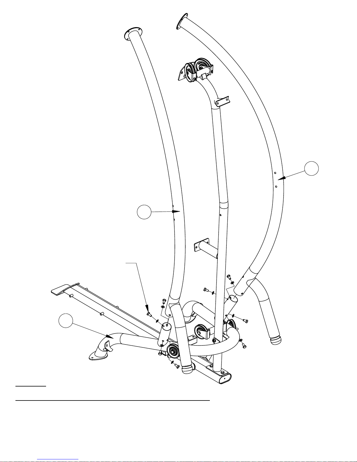
Page 22

31
18
11
4-Plastic Balls
4-Cable "U" Brackets
4-M6x12 Button Head Bolts
4-M6 T-Nuts
4-Spring Clips
22
20
12
PAGE 19
Page 23

32
2-M10x100
Hex Bolts
33
2917
Step 17
Slide the C shaped Shroud Bracket into the pocket at one end of Shroud. (Pocket A
seam should face the inside). Work the shroud around the bracket until the
opening in the back of the shroud lines up with the hole on the back of the bracket.
Repeat this on the opposite end of the shroud.
Now position the shroud assembly around the upper and lower Shroud Mount Plates B
by working around the guide rods and stack. Align the holes at the top and bottom
brackets with the holes in the plates and insert T-Pins (33) in each hole (3 on top and
3 on bottom).
Secure the Top Shroud Plate (17) using the 2-M10x100 Shroud Tensioning Bolts on C
the Top Beam Assembly (16). Stretch the shroud tight by threading the bolts at the
top. Work between the 2 bolts to adjust each side evenly.
PAGE 20
Page 24

30
30
43
Step 18
Attach the D-Handle Straps (30, 43) to the cable ends with Spring Clips (67).A
PAGE 21
Page 25

DECAL REFERENCE
Page 22
Page 26

DECAL REFERENCE
Page 23
Page 27

(
)
(
)
(
)
DECAL PLACEMENT
“Inspire M1”
below logo
label (45 x 33)
Weight # labels
(1 – 21),
included with
manual. Silver
#’s on black
background. (18
x 25)
“DANGER, THIS PRODUCT
NOT DESIGNED FOR
COMMERCIAL USE” on
base in front (80 x 40)
“WARNING”
Label on side
of upright.
40 x 170
“NOTICE”
Label on side
of upright,
under
warning label.
(40 x 170)
“WARNING, PINCH
POINTS” on top of
seat frame & in front
of weights. (40 x 25)
Page 24
Serial # label
40 x 30
“Patent” Label
placed just above
the “Notice” label
50 x 30
Page 28

HOME GYM OPTIONS (Sold Separately)
• Heavy Stack (50lbs)
• Revolving Lat Bar
• Revolving EZ Curl Bar
• Ankle Strap
Training Tips
CONSULT A PHYSICIAN BEFORE STARTING ANY EXERCISE PROGRAM
1. Always warm up before you start weight training. This helps get
your muscles warm and prevents injury. You can warm up with light
cardio or by doing a light set of each exercise before going to heavier
weights.
2. Control the weight. Always work with a weight that you can handle
through a full range of motion. Slow and steady movements are
recommended.
3. Breathe. Don’t hold your breath during your set. Holding your
breath builds internal pressure which increases your change for broken
blood vessels, as well as a hernia.
4. Sit up straight. Pay attention to your posture and keep everything
straight. Engage your abs in every movement to keep balanced and
protect your spine.
Page 25
Page 29

GENERAL MAINTENANCE INFORMATION
Warning: DO NOT place styrofoam or printed materials on the
orthopedic seat pads. Over time, these may stick to the pads and
mar the surface.
Do not leave items sitting on the orthopedic seat pads, these pads
have a special density that takes shape to objects and small objects
will leave imprints in the surface that may take time to come out.
• Periodically inspect the cables for splitting, cracking or fraying. Also,
watch for bulging or flat areas in the cable.
• Immediately replace cables at the first signs of damage or wear. Never
use equipment with damaged or worn cables.
• Cables naturally stretch over time, so check cable slack periodically and
adjust cable tension as needed. See Step 55 to adjust cable tension.
• Regularly inspect product for loose hardware.
• Do not use or store equipment outdoors.
• Inspect snap links, swivels, handles and weight stack pin for wear or
damage. If wear or damage exists, replace immediately.
• Locate and familiarize yourself with all warning decals on the home gym.
• Replace damaged or worn upholstery immediately.
• Periodically wipe down guide rods with a dry cloth and re-apply a thin coat
of a teflon-based lubricant.
Page 26
Page 30

MAINTENANCE SCHEDULE
ROUTINE
Inspect: Links, Pull Pins,
Spring Clips, Swivels,
Weight Stack Pins
Clean: Upholstery
Inspect: Cables and
their Fittings
Inspect: Tautness of all
Shrouds
Inspect: Accessory Bars
and Handles
Inspect: All Decals
HOME
MAINTENANCE
WEEKLY
WEEKLY
WEEKLY
WEEKLY
3 MONTHS
3 MONTHS
ENTRY DATE
Inspect: All Nuts and
Bolts. Tighten if Needed
Inspect: Anti-Skid
surfaces
Clean and Lubricate:
Guide Rods with a Teflon
based lubricant
Lubricate: Seat Sleeves
and all Plastic Slides
Clean and Wax: All
Glossy Finishes
Replace: Cables, Belts
and Connecting Parts
3 MONTHS
3 MONTHS
3 MONTHS
3 MONTHS
YEARLY
2 YEARS
Page 27
Page 31

LIMITED WARRANTY
In-Home Lifetime Warranty.
This Warranty applies only in the United States to Inspire Strength products manufactured or distributed by Health In
Motion LLC. The warranty period to the original purchaser is lifetime of the original purchaser.
Health In Motion warrants that the Product you have purchased for non-commercial, personal, family or household
use from Health In Motion LLC or from an authorized Health In Motion reseller is free from defects in materials or
workmanship under normal use during the warranty period. Your sales receipt, showing the date of purchase of the
Product, is your proof of the date of purchase. This warranty extends only to you, the original purchaser. It is not
transferable to anyone who subsequently purchases the Product from you. It excludes expendable parts such as paint
and finish. This Warranty becomes VALID ONLY if the Product is assembled / installed according to the instructions /
directions included with the Product.
Replacement and repair of parts.
During the warranty period Health In Motion will at no additional charge, repair or replace the Product if it becomes
defective, malfunctions, or otherwise fails to conform with this Warranty under normal non-commercial, personal,
family, or household use. In repairing the product Health In Motion may replace defective parts with, at the option of
Health In Motion, serviceable used parts that are equivalent to new parts in performance, or new parts. All exchanged
parts and Products replaced under this warranty will become the property of Health In Motion. Health In Motion
reserves the right to change manufacturers and or specification of any part to cover any existing warranty.
Service procedures.
To obtain warranty parts, you must return the parts to Health In Motion or an authorized Health In Motion retailer in
its original container (or equivalent). You must pre-pay any shipping charges, taxes, or any other charges associated
with transportation of the Product. In addition, you are responsible for insuring any Product shipped or returned. You
assume the risk of loss during shipment. You must present Health In Motion with proof-of-purchase documents
(including the date of purchase, Model, and Serial Number). Any evidence of alteration, erasing or forgery of proof of-purchase documents will be cause to void this Warranty.
Conditions and Exceptions.
This Warranty does not extend to any Product not purchased from Health In Motion LLC or from an authorized Health
In Motion reseller. This Warranty does not extend to any Product that has been damaged or rendered defective; (a)
as a result of accident, misuse, or abuse; (b) by the use of parts not manufactured or sold by Health In Motion; (c) by
modification of the Product; (d) as a result of service by anyone other than Health In Motion, or an authorized Health
In Motion warranty service provider; (e) product that has not been properly maintained (follow maintenance schedule
found on product). Should any product submitted for Warranty service be found to be ineligible, an estimate of repair
cost will be furnished and the repair will be made if requested by you upon Health In Motion receipt of payment or
acceptable arrangement of payment.
Disclaimer
EXCEPT AS EXPRESSLY SET FORTH IN THIS WARRANTY HEALTH IN MOTION MAKES NO OTHER WARRANTIES;
EXPRESSED OR IMPLIED INCLUDING ANY IMPLIED WARRANTIES OF MERCHANTABILITY AND FITNESS FOR A
PARTICULAR PURPOSE. HEALTH IN MOTION EXPRESSLY DISCLAIMS ALL WARRANTIES NOT STATED IN THIS
WARRANTY. ANY IMPLIED WARRANTIES THAT MAY BE IMPOSED BY LAW ARE LIMITED TO THE TERMS OF THIS
WARRANTY. NEITHER HEALTH IN MOTION NOR ANY OF ITS AFFILIATES SHALL BE RESPONSIBLE FOR INCIDENTAL
OR CONSEQUENTIAL DAMAGES. HEALTH IN MOTION IS NOT RESPOSIBLE FOR THE REPAIR OR REPLACEMENT OF
ANY PARTS THAT HEALTH IN MOTION DETERMINES HAVE BEEN SUBJECTED AFTER THE DATE OF MANUFACTURE TO
ALTERATION, NEGLECT, ABUSE, MISUSE, NORMAL WEAR & TEAR, ACCIDENT, DAMAGE DURING TRANSIT OR
INSTALLATION, FIRE, FLOOD, OR ANY ACT OF GOD. SOME STATES DO NOT ALLOW LIMITATIONS ON HOW LONG AN
IMPLIED WARRANTY LASTS OR THE EXCLUSION OR LIMITATION OF INCIDENTAL OR CONSEQUENTIAL DAMAGES, SO
THE ABOVE LIMITATIONS OR EXCLUSION MAY NOT APPLY TO YOU. This Warranty gives you specific legal rights and
you may also have other rights that may vary from state to state. This is the only express warranty applicable to
Health In Motion’s “Inspire” branded strength products. Health In Motion neither assumes nor authorizes anyone to
assume for it any other express warranty.
Page 28
 Loading...