

Page 1
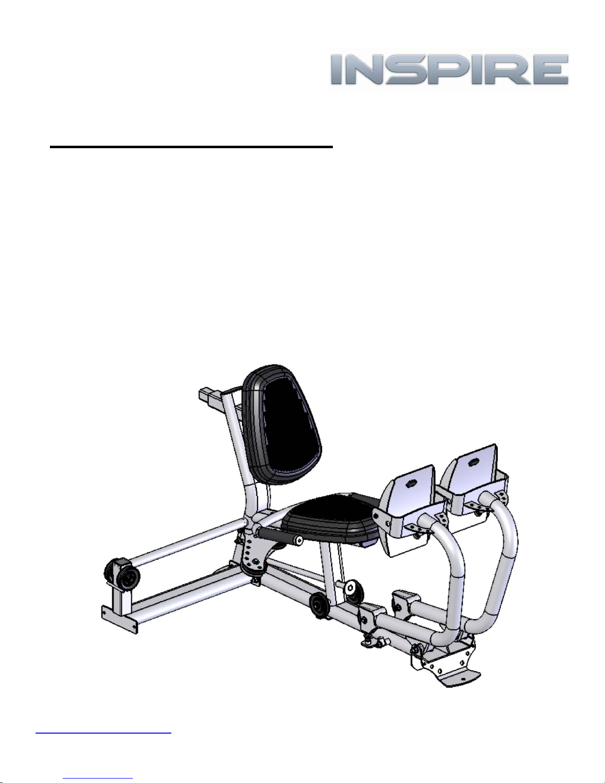
LP2-M5 Attachment Kit
Use this addendum to attach the LP2 to the M5 mach i ne.
Verify all parts and hardware in this kit using this
addendum.
Verify all parts and hardware for the LP2 base unit using
the Owner’s Manual in the LP2 box.
www.inspirefitness.net by Health In Motion LLC Mar 2012
Page 2

Th e foll owi ng parts are in th e LP2-M5 At t achm ent K i t box
Item
Parts Description Qty
Qty
Rec'd
Item Hardware Description Qty
Qty
Rec'd
1 Attachment Arm 1 1 Bolt, M10*45 2
2 3 1/2" Pulley 3 2 Bolt, M10*95 1
3 Floating Pulley Plates 2 3 Bolt, M10*105 1
4 LP2-M5 Cable 1 4 Bolt, M10*115 1
5 Bolt, M10*120 1
6 Bolt, M10*125 2
7 Flat Washer, M10 12
8 Lock Nut, M10 6
PART S & HARDWARE LIST
Th e parts an d hardware l i st for t he LP2 base un i t is in t he LP2 Owner's
Manual.
NOTE: Parts and hardware in this LP2-M5 Attachment Kit
box are Metric sizes and cannot be mixed with the
American size parts and hardware in the LP2 box.
Page 1
Page 3
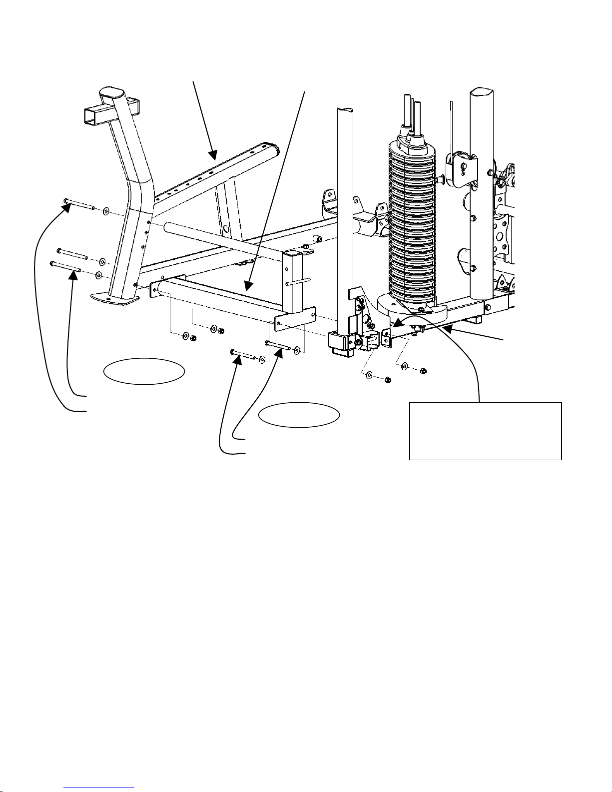
Main Frame
Leg Press Base
Attachment Arm
Before attaching Attachment Arm,
STEP 1
STEP 2
2 – M10 x 125 Hex Bolts
1 – M10 x 120 Hex Bolt
5 – M10 Flat Washers
2 – M10 Lock Nuts 1 – M10 x 105 Hex Bolt
1 – M10 x 95 Hex Bolt
4 – M10 Flat Washers
2 – M10 Lock Nuts
Step 1: Remove the M10 x 100 Hex Bolt connecting the
Corner Bracket to the Main Frame.
Attach Attachment Arm to Main Frame using: One (M10 x 105 Hex Bolt)
(Finger Tighten Only) Four (M10 Flat Washers)
Two (M10 Lock Nuts)
Step 2: Attach Leg Press Base to Attach ment Arm using: Two (M10 x 125 Hex Bolts)
One (M10 x 1 2 0 Hex Bolt)
Five (M10 Flat Washers)
(Wrench Tighten Bolts in Steps 1 & 2 Now) Two (M10 Lock Nuts)
Note: Hardware in Steps 1 & 2 are metric size and cannot be mixed with the other
hardware in the L P2 .
Page 2
remove this M10 x 100 Hex Bolt
connecting the Corner Bracket to
the Main Frame
One (M10 x 95 Hex Bolt)
Page 4

STEP 3
STEP 4
Press Arms
`
Leg Press Base
Dual Pulley Mount
Short end of tube
faces outward
1 – 1/2” x 10 ¾” Hex Bolt 2 – 5” Hex Bolts
2 – 1/2” Flat Washers 4 – 3/8” Flat Washers
1 – 1/2” Lock Nut 2 – 3/8” Lock Nuts
Caution: Press arms are unstable until the
cables are attached. It is recommended to
lay the press arms forward onto a protective
surface until the cables are installed.
Step 3: Attach Dual Pulley Mount to Leg Press Base using:
Two (3/8” x 5” Hex Bolts)
Four (3/8” Flat Washers)
Step 4: Attach Press Arms to Leg Press Base using:
One (1/2” x 10 ¾” Hex Bolt)
Two (1/2” Flat Washers)
One (1/2” Lock Nut)
Note: Leg Press Arms angle outward from Leg Press Frame,
short end of tube faces outward.
(Wrench Tighten Bolts) Two (3/8” Lock Nuts)
(Wrench Tighten Bolts, Assembly Should Move Freely.)
Page 3
Page 5

Leg Press Base
Press Arms
Attachment Arm
STEP 8
STEP 6
STEP 5
Pulley-7 & 8
STEP 7
Pulley-5 & 6
Pulley-1 & 2
Pulley-3 & 4
2 – 3 ½” Pulleys
1 – M10 x 115 Hex Bolt
2 – M10 Flat Washers
1 – M10 Lock Nut
2 – 3 ½” Pulleys
2 – 2” Hex Bolts
4 – 3/8” Flat Washers
2 – 3/8” Lock Nuts
2 – 3 ½” Pulleys 2 – 3 ½” Pulleys
2 – 2” Hex Bolts 2 –1 ¾” Hex Bolts
4 – 3/8” Flat Washers 2 – 3/8” Flat Washers
2 – 3/8” Lock Nuts
Step 5: Attach Pulleys 1 & 2 to Press Arms using: Two (3 ½” Pulleys)
Two (3/8” x 2” Hex Bo l ts)
Four (3/8” Flat Washers)
(Wrench Tighten Bolts) Two (3/8” Lock Nuts)
Step 6: Attach Pulleys 3 & 4 to Leg Press Base using: Two (3 ½” Pulleys)
(Wrench Tighten Bolts) Two (3/8” Flat Washers)
Two (3/8” x 1 ¾” Hex Bolts)
Step 7: Attach Pulleys 5 & 6 to Dual Pulley Mount using: Two (3 ½” Pulleys)
Two (3/ 8” x 2” Hex Bolts)
Four (3/8” Fla t W ashers)
Step 8: Attach Pulleys 7 & 8 to Attachment Arm using: Two (3 ½” Pulley)
(Wrench Tighten Bolts) Two (3/8” Lock Nuts)
One (M10 x 115 Hex Bolt)
Two (M10 Flat Washers)
NOTE: Hardware and Pulleys in Step 8 are metric size and cannot be mixed with the
other Hardware or Pulleys.
(Wrench Tighten Bolts) One (M10 Lock Nut)
Page 4
Page 6

Cable End with
Bushing
Pulley 1
Pulley 3
Pulley 5
Pulley 7
Pulley 8
Pulley 6
Pulley 9
Pulley 4
Pulley 2
STEP 9
STEP 11
STEP 10
Leg Press Base
Previously installed 3 ½” Pulley
And Lat Upper Cable
Remove these items from machine.
in Step 10.
Save Washers and Lock Nut for use
2 – M10 x 45 Hex Bolts
4 – M10 Flat Washers
2 – M10 Lock Nuts
1 – 8” Hex Bolt
2 – 3/8” Small OD
Washers
1 – 3/8” Lock Nut
Step 9: Remove the two Bolts, three Washers, one Lock Nut, Mounting Bracket, and Barrel
Spacer from the Upper Pulley on the M5. Save the Washers and Lock Nut for use in
Step 10. Leave the Lat Upper Cable wrapped around this pulley.
Step 10: Attach the previously installed 3 ½” Pulley and Two (M10 x 45 Hex Bolts)
Pulley 9 to two Floating Pulley Plates using: F o ur (M10 Flat Washers)
Two ( M10 Lock Nuts)
Step 11: Attach one Cable End with Bushing to one end of the cable as shown. Attach the Cable
End, Bushing, and 3/8” Washer to the Leg Press Base with the 8” Hex Bolt. Run the
other end of the cable around Pulleys 1, 3, 5, 7, 9, 8, 6, 4, and 2. Attach the other
Cable End with Bushing to this end of the cable and attach to the 8” bolt with one 3/8”
Washer and 3/8” Lock Nut.
Note: Hardware in Steps 9 & 10 are metric sizes. Do not mix hardware from Steps 9 &
10 with Hardware in Step 11.
Page 5
Page 7

Attach Seat & Handle to
Seat Base
Leg Press Base
Seat Base
STEP 14
STEP 12
STEP 13
Handles
Seat Pad
Seat Pad
Back Pad Stem
Attach Seat & Handle
STEP 15
2 – 1” Hex Bolts
2 – 3/8” Flat Washers
2 – 2 ½” Hex Bolts
4 – 3/8” Flat Washers
2 – 3/8” Lock Nuts
these sets of holes for
more pre-Stretch
2 – 2 ½” Hex Bolts
2 – 3/8” Flat Washers
Step 12: Attach Handles to Leg Press Base using: Two (3/8” x 2 ½” Hex Bolts)
Four (3/8” Flat Washers)
(W re nch T ighte n Bo lts ) Two (3/8” Lock Nuts)
Step 13: Attach Seat Base to Back Pad Stem using: Two (3/8” x 1” Hex Bolts)
(Wrench Tighten Bolts) Two (3/8” Flat Washers)
Step 14: Attach Seat Base to Leg Press Base using: Two (3/8” x 2 ½ ” Hex Bolts)
(Wrench Tighten B ol ts ) Two (3/8” Flat Washers)
Step 15: Install the Seat Pads into the Seat Bases by working the edges of the pads into the
to these sets of holes
for more leg room
groove around the Seat Bases. Do no t use s harp o bjects during installation of
the pads.
Page 6
Page 8

Foot Plates
3/8” Barrel
Rubber Bumper Pads
STEP 17
STEP 18
Press Arms
STEP 16
4 – 3/8” Bar r el Spacers
4 – 1” Button Head Bolts
4 – 3/8” Small OD Washers
4 – 3/8” Thin Lock Nuts
Spacer
Step 16: Install Two Adjustable Bumpers.
Step 17: Attach Foot Plates to Press Arms with Rubb er
Bumper Pads towards top as shown using: Four (3/8” Barrel Spacers)
Four (3/8” x 1” Button Head Bolts)
Install Bolts, Washers, and 3/8” Bushings Four (3/8” Small OD Washers)
first, and tighten the Bolts. Next, attach Four (3/8” Thin Lock Nuts)
the Thin Lock Nuts and tighten.
(Tighten Bolts with 6mm Allen Wrench)
Step 18: Foot Plate Stop Adjustment:
To adjust Foot Plate Stop angle, loosen jam nut, screw in or out the Adjustable
Bumper, and retighten the Jam Nut.
Page 7
Page 9

Adjustable Bumpers
Press Arms
STEP 19
Store Locking
Rod here
Step 19: To connect both Press Arms together, slide Locking Rod thru both Press Arm
Brackets and tighten Adjustable Bumpers against Locking Rod to secure
Locking Rod in place.
Store Locking Rod in Leg Press Base as shown when not in use.
Page 8
 Loading...