

Inspire LEG PRESS OPTION Assembly & Operation Manual
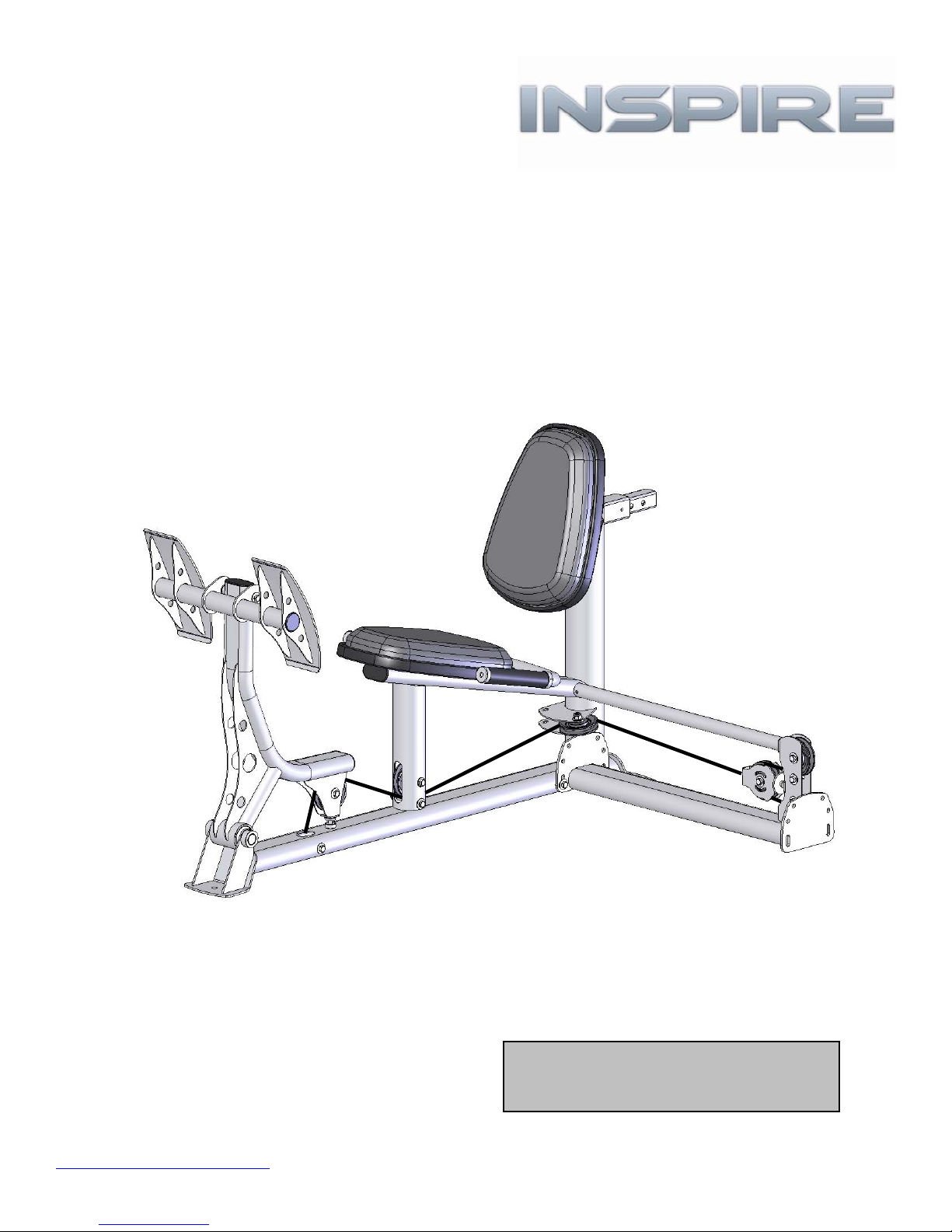
ASSEMBLY & OPERATION MANUAL
LEG PRESS OPTION
RECORD SERIAL NUMBER HERE
www.inspirefitness.net by Health In Motion LLC Sept. 2006

TABLE OF CONTENTS
Section Description………………………………………………….. Page
Instructions………………………………………………………………….. 1
Tools Requires……………………………………………………………… 1
Parts & Hardware List………………………………………………….. 2
Hardware Sizing Chart ………………………………………………… 3
Assembly Instructions (M1 & M2)……………………………….. 4-10
Assembly Instructions (M3)………….…………………………….. 11-16
Decal Reference……………………………………………………………. 17
Decal Placement…………………………………………………………… 18
General Maintenance Information…….………………………… 19
Maintenance Schedule…….………………………………………….. 20
Limited Warranty.………………………….……………………………. 21

BEFORE ASSEMBLING YOUR LEG PRESS
IMPORTANT: Read this entire manual before attempting to build or use
your leg press. This manual contains step by step instructions for proper
assembly.
Use the parts list included in this manual to verify that all parts are
accounted for before assembly. If any parts are missing, contact the retailer
of this home gym for replacement parts. Or, call Inspire at 714-738-1729
Service of your home gym should only be preformed by an authorized
INSPIRE retailer. Service preformed by anyone else can result in loss of
warranty. Use only Inspire replacement parts on this machine. The use of
any other brand of parts can also result in a loss of warranty. If you need
help finding an authorized retailer, please contact us directly:
Inspire Fitness
637 S. State College Blvd.
Fullerton, CA 92831
Ph: 714-738-1729
Fx: 714-738-1728
www.inspirefitness.net
TOOLS REQUIRED FOR ASSEMBLY
• Standard socket set (including 9/16” and 1/2” sockets)
• 9/16” wrench
• Adjustable wrench
• Tape Measure
• Rubber Mallet
PAGE 1

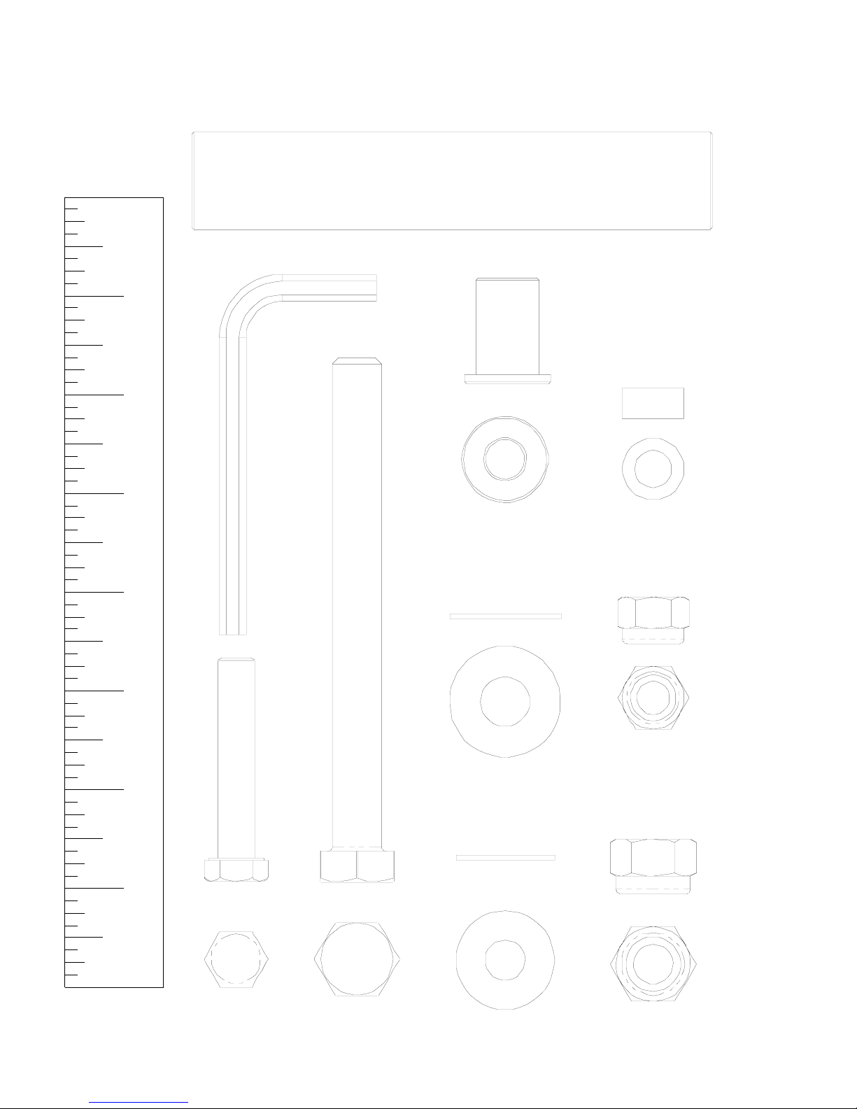
PARTS & HARDWARE LIST
Item Parts Description Qty
1 Leg Press Base 1 1 Bolt, 3/8-16 x 1" L 2
2 Press Arm 1 2 Bolt, 3/8-16 x 2" L 6
3 Foot Plate 1 3 Bolt, 3/8-16 x 2 1/4" L 2
4 Handles 1 4 Bolt, 3/8-16 x 2 1/2" L 2
5 Attachment Arm 1 5 Bolt, 3/8-16 x 3 3/4" L 3
6 Back Pad Stem 1 6 Bolt, 3/8-16 x 4 1/4" L 3
7 Floating Pulley Bracket Assembly 1 7 Bolt, 3/8-16 x 4 3/4" L 1
8 Orthopedic Pads 2 8 Bolt, 3/8-16 x 5" L 3
9 LP1 Cable 1 9 Bolt, 1/2-13 x 5" L 1
10 Seat Base 2
11 3 1/2" Pulley 5 10 3/8" Washer 29
11 1/2" Washer 2
12 3/8-16 Locknut 13
13 1/2-13 Locknut 1
14 Step Spacer, 1" Long 2
15 Barrel Spacer, 5/16” Long 1
16 Cable Adapter 1
17 Pivot Shaft 1
18 4 mm Wrench 1
NOTE: There May Be Extra Parts Left Over Depending On Which Machine
You Attach the LP1 Too.
Qty
Rec'd
PAGE 2
Item Hardware Description Qty
Qty
Rec'd
HARDWARE SIZING CHART
Pi vot S ha ft
1" 2" 3" 4" 5" 6" 7"
3/8" DIA. Bolt Allen Wrench
1/2" DIA. Bolt
1/2" Locknut 3/8" Locknut 5/16" Barrel Spacer
3/8" Washer 1/2" Washer Step Spacer
ACTUAL PARTS MAY BE SMALLER OR LARGER THAN SHOWN
PAGE 3
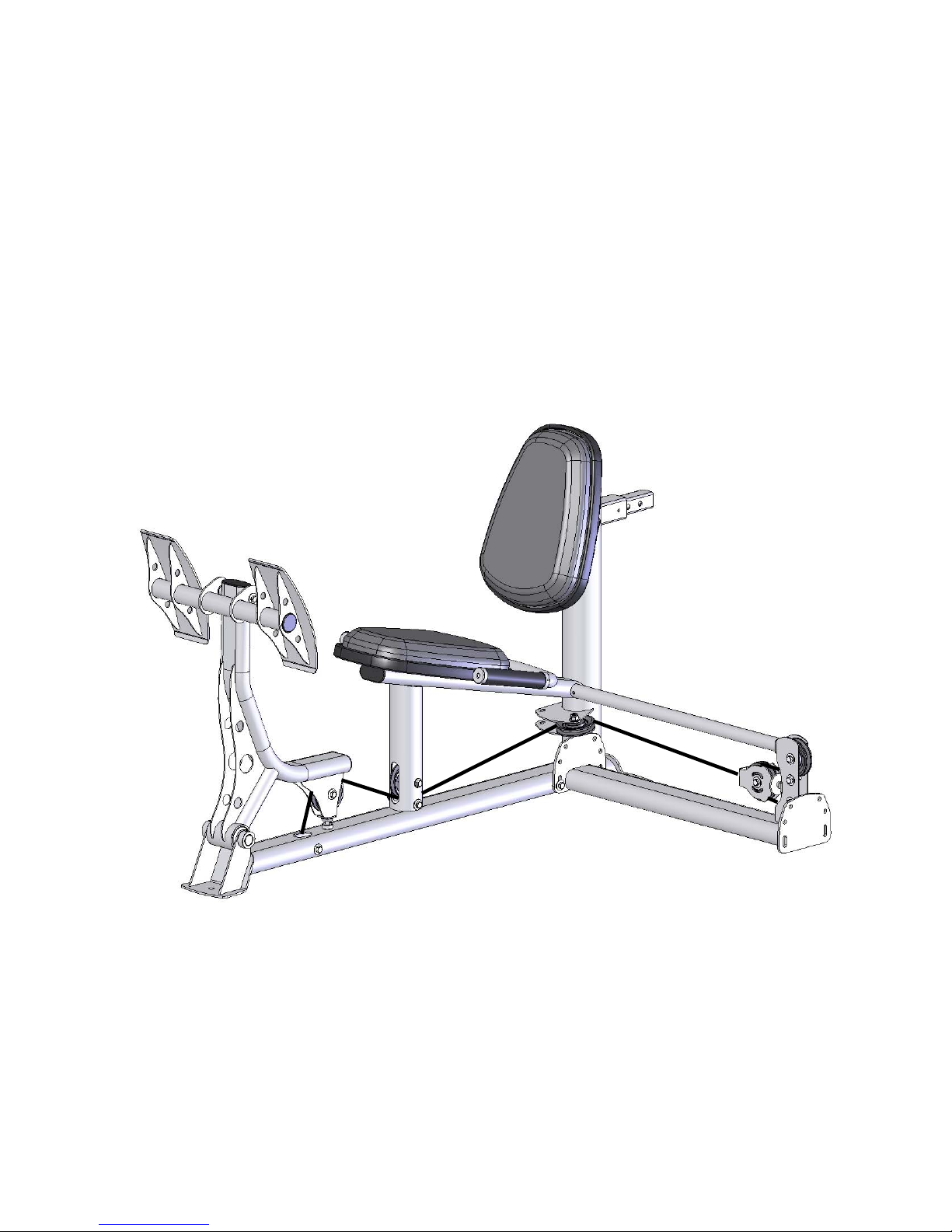
ASSEMBLY INSTRUCTIONS
PAGE 4
Assembly Procedure for Attaching Leg Press to M1 & M2
Go directly to page 11 if attaching Leg Press to M3
NOTE: The Leg Press may be attached to either side of the machine.
The pictures show only one side
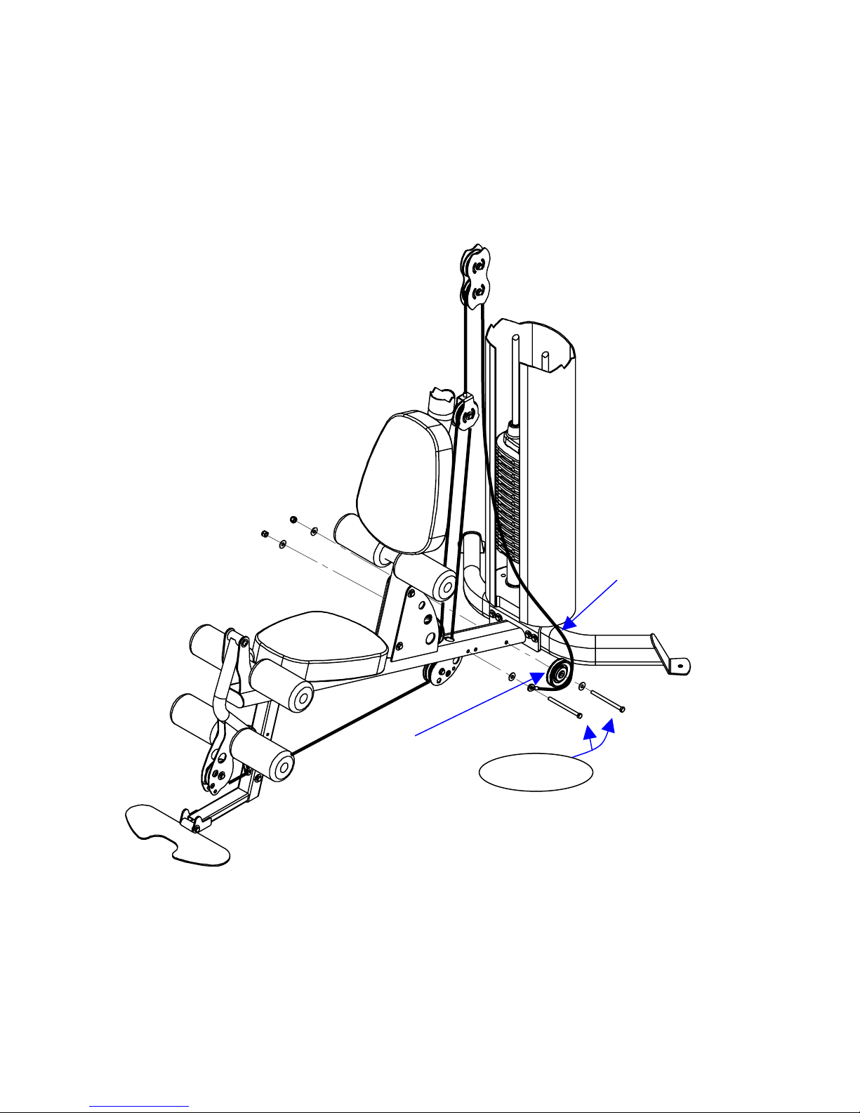
Lower Cable
Pulley 1
Disconnect Cable and
Remove Pulley 1
Step 1: Remove Pulley 1 and disconnect lower cable from Home Gym. Retain pulley 1
and hardware for future steps.
Page 5
STEP 1
 Loading...