

Page 1
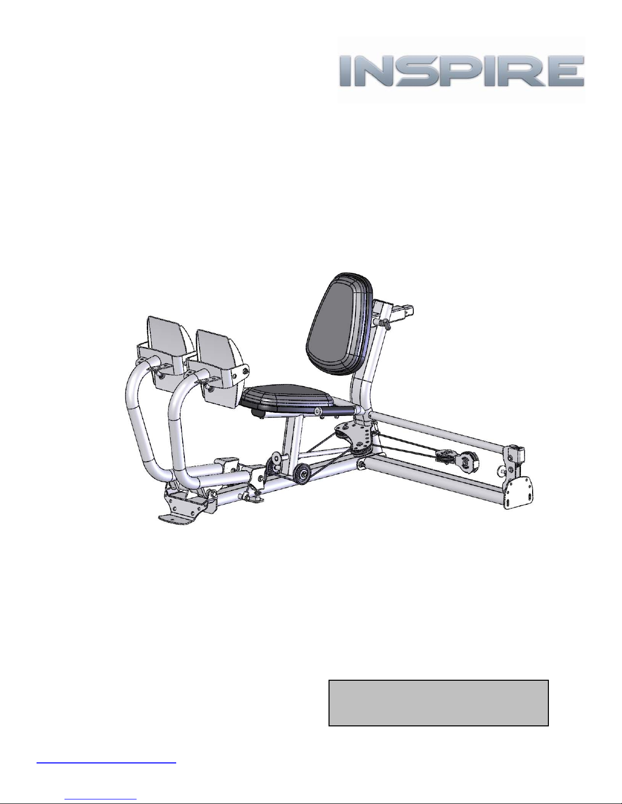
ASSEMBLY & OPERATION MANUAL
LEG PRESS 2 OPTION
RECORD SERIAL NUMBER HERE
www.inspirefitness.net
by Health In Motion LLC 10-30-07
Page 2

TABLE OF CONTENTS
Section Description………………………………………………….. Page
Instructions………………………………………………………………….. 1
Tools Required……………………………………………………………… 1
Parts & Hardware List………………………………………………….. 2
Hardware Sizing Chart ………………………………………………… 3
Cable Chart …………………………………………………………………. 4
Assembly Instructions – attaching to M1 & M2 …………. 6
Assembly Instructions – attaching to M3……….………….. 9
Assembly Instructions – attaching to M4……….………….. 12
Decal Reference……………………………………………………………. 21
Decal Placement…………………………………………………………… 22
General Maintenance Information…….………………………… 23
Maintenance Schedule…….………………………………………….. 24
Limited Warranty.………………………….……………………………. 25
Page 3

BEFORE ASSEMBLING YOUR LEG PRESS
IMPORTANT: Read this entire manual before attempting to build or use
your leg press. This manual contains step by step instructions for proper
assembly.
Use the parts list included in this manual to verify that all parts are
accounted for before assembly. If any parts are missing, contact the retailer
of this home gym for replacement parts. Or, call Inspire at 714-738-1729
Service of your home gym should only be preformed by an authorized
INSPIRE retailer. Service preformed by anyone else can result in loss of
warranty. Use only Inspire replacement parts on this machine. The use of
any other brand of parts can also result in a loss of warranty. If you need
help finding an authorized retailer, please contact us directly:
Inspire Fitness
637 S State College Blvd.
Fullerton, CA 92831
Ph: 714-738-1729
Fx: 714-738-1728
www.inspirefitness.net
TOOLS REQUIRED FOR ASSEMBLY
• Standard socket set (including 9/16” and 3/4” sockets)
• 9/16” wrench
• 3/4” wrench
• Adjustable wrench
• Tape Measure
• Rubber Mallet
PAGE 1
Page 4

PARTS & HARDWARE LIST
Item Parts Description Qty
1 Leg Press Base 1 1 Bolt, 3/8-16 x 1" L Button Head 4
2 Press Arm, Left 1 2 Bolt, 3/8-16 x 1" L 2
3 Press Arm, Right 1 3 Bolt, 3/8-16 x 1 1/4" L 2
4 Foot Plate 2 4 Bolt, 3/8-16 x 1 3/4" L 2
5 Leg Press Attachment Arm 1 5 Bolt, 3/8-16 x 2" L 10
6 Back Pad Stem 1 6 Bolt, 3/8-16 x 2 1/2" L 4
7 Dual Pulley Mount 1 7 Bolt, 3/8-16 x 3 3/4" L 1
8 Seat Base 2 8 Bolt, 3/8-16 x 4 1/4" L 2
9 Handle Assy 1 9 Bolt, 3/8-16 x 4 3/4" L 1
10 Floating Dual Pulley Bracket 1 10 Bolt, 3/8-16 x 5" L 5
11 LP2-M4 Attachment Cable 1 11 Bolt, 3/8-16 x 8" L 1
12 Locking Rod 1 12 Bolt, 1/2-13 x 10 3/4" L 1
13 3 1/2" Pulley 9
14 LP2 Main Cable 1 13 3/8" Washer 41
14 3/8" Small OD Washer 6
16 3/8-16 Locknut 18
17 3/8-16 Thin Locknut 4
18 1/2-13 Locknut 1
19 Barrel Spacer, 5/16” Long 1
20 Barrel Spacer, 3/8” Long 4
21 Cable End with Bushing 2
22 Cable Adapter 1
Qty
Rec'd
Item Hardware Description Qty
15 1/2" Washer 2
23 Adjustable Bumper 2
24 6mm Allen Wrench 1
Qty
Rec'd
Note: There may be extra hardware left over depending on which machine
the LP2 is attached.
PAGE 2
Page 5
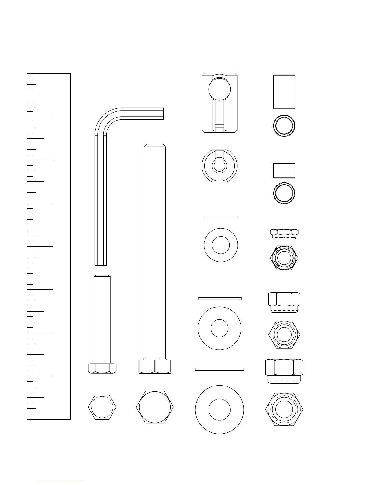
HARDWARE SIZING CHART
1" 2" 3" 4" 5" 6" 7"
3/8" DIA. Bolt Allen Wrench
1/2" DIA. Bolt
PAGE 3
1/2" Washer 3/8" Washer 3/8" Small OD Washer Cable End
1/2" Locknut 3/8" Locknut 3/8" Thin Locknut 3/8" Barrel Spacer Bushing Sleeve
ACTUAL PARTS MAY BE SMALLER OR LARGER THAN SHOWN
Page 6
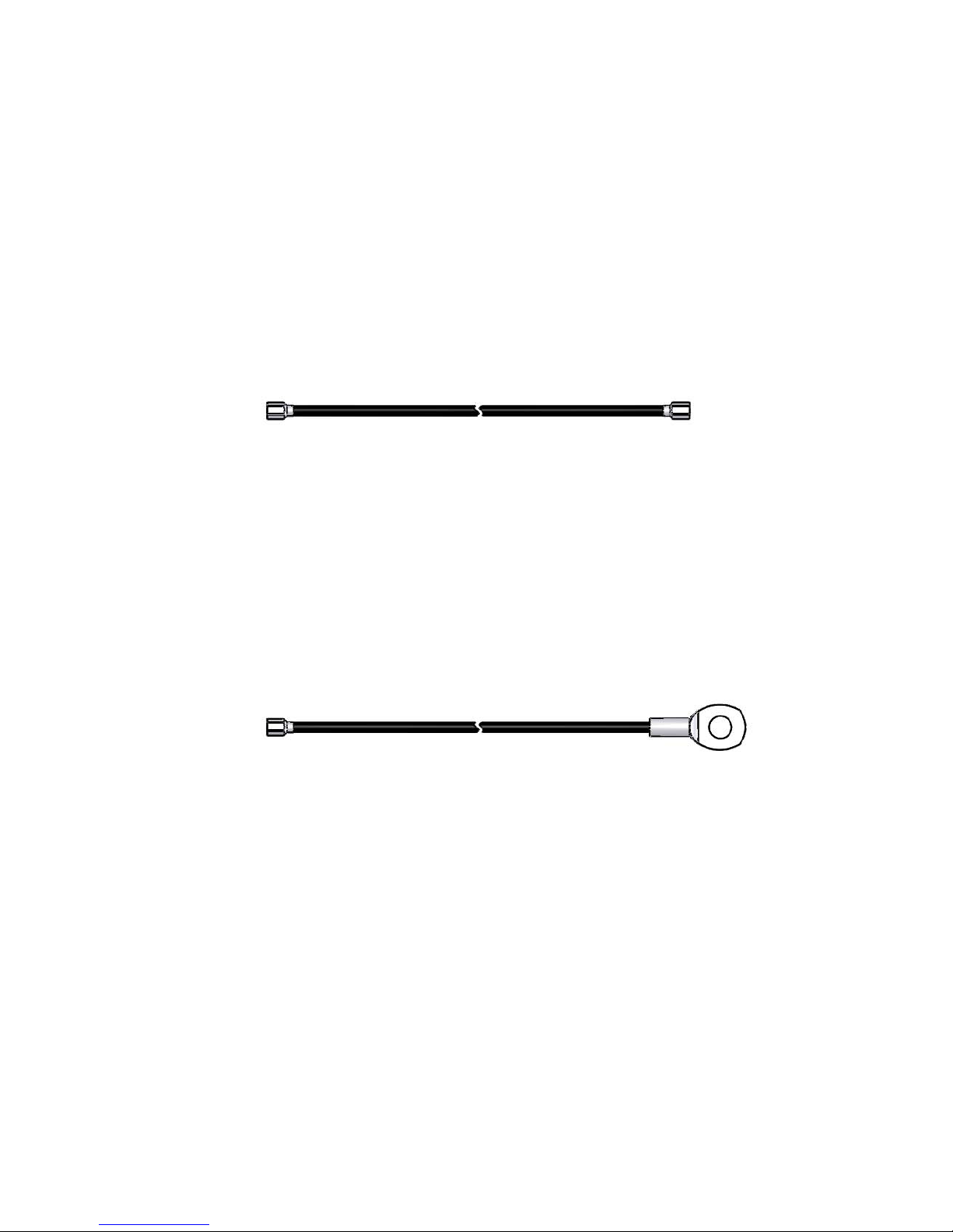
CABLE CHART
LP2 Main Cable
LP2-M4 Attachment Cable
Page 4
Page 7
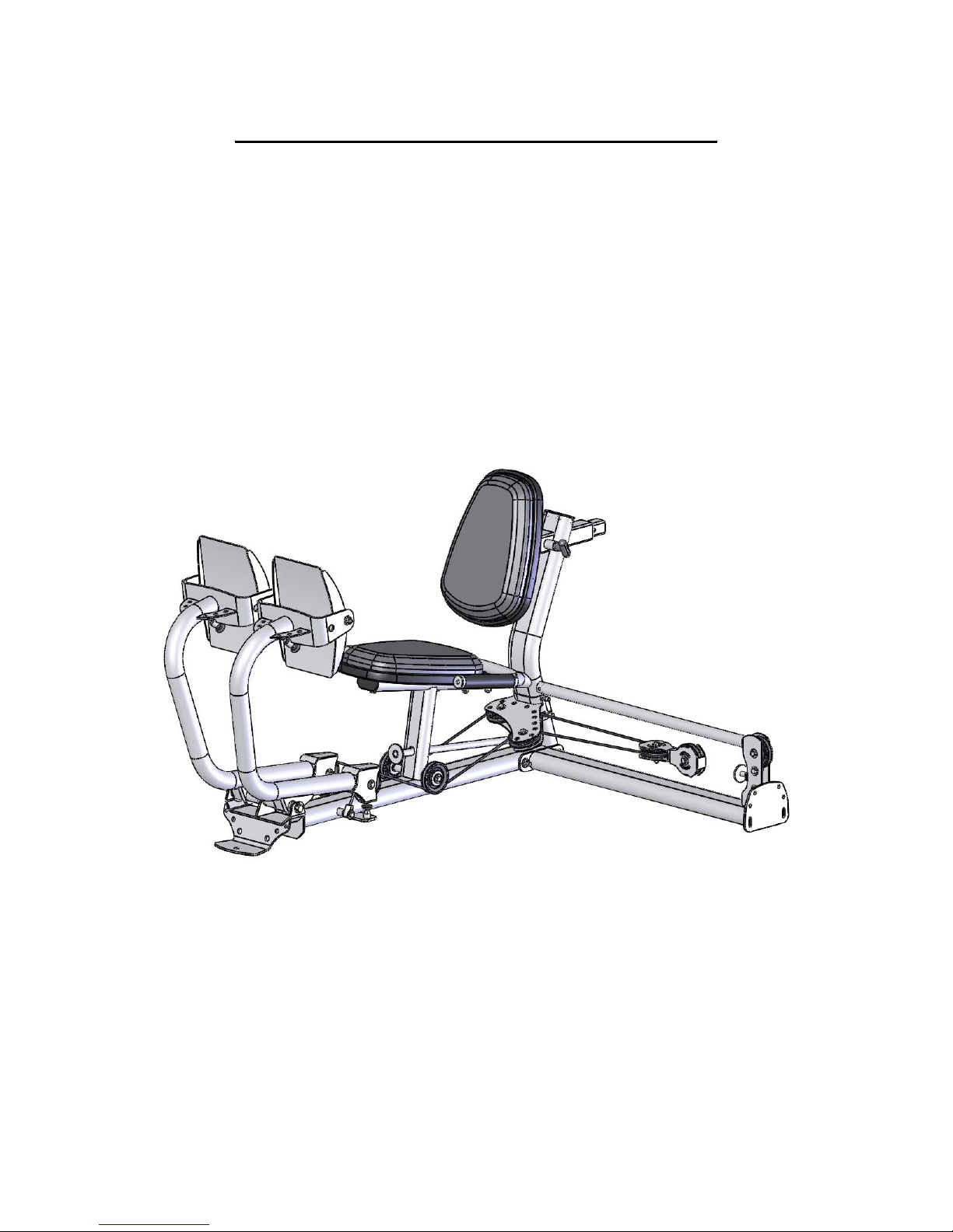
Assembly Instructions Leg Press 2
Assembly Procedures for attaching LP2 to Home Gym
Refer to page 6 if attaching to M1 & M2
Refer to page 9 if attaching to M3
Refer to page 12 if attaching to M4
Page 5
Page 8
Assembly Procedure for attaching Leg Press 2 to M1 & M2
NOTE: The Leg Press may be attached to either side of the Home Gym.
The Illustrations show only one side.
Disconnect Cable &
Remove Pulley 1
Step 1: Remove Pulley 1 and disconnect Lower Cable from Home Gym. Retain
Pulley 1 and hardware for later use.
Page 6
Lower Cable
Page 9

S
STEP 3
2 – 5” Hex Bolts 1 – 4 ¾” Hex Bolt
4 – 3/8” Flat Washers 1 – 3/8” Flat Washer
2 – 3/8” Lock Nuts
Leg Press Base Attachment Arm
TEP 2
2 – 5” Hex Bolts
Home Gym 4 – 3/8” Flat Washers
2 – 3/8” Lock Nuts
Step 2: Attach Attachment Arm to Home Gym using: Two (3/8” x 5” Hex Bolts)
(Finger Tighten Only) Four (3/8” Flat Washers)
Two (3/8” Lock Nuts)
Step 3: Attach Leg Press Base to Attachment Arm using: Two (3/8” x 5” Hex Bolts)
Five (3/8” Flat Washers)
Two (3/8” Lock Nuts)
(Wrench Tighten Bolts in Steps 2 & 3 Now) One (4 ¾” Hex Bolt)
Page 7
Page 10

STEP 5
STEP 4
Pulley-8
1 – 3 ½” Pulley 1 – 3 ½” Pulley
1 – 2” Hex Bolt 1 – 2” Hex Bolt
2 – 3/8” Flat Washers 2 – 3/8” Flat Washers
1 – 3/8” Lock Nut 1 – 3/8” Lock Nut
1 – 3/8” Lock Nut
Pulley-9
Floating Dual
Pulley Bracket
STEP 6
1 – 2” Hex Bolt
2 – 3/8” Flat Washers
STEP 7
Cable
Retainer
Bolt
1 – 2” Hex Bolt
2 – 3/8” Flat Washers
1 – 3/8” Lock Nut
Step 4: Attach Pulley 8 to Attachment Arm using:
One (3 ½” Pulley)
One (3/8” x 2” Hex Bolt)
Two (3/8” Flat Washers) One (3/8” Lock Nut)
Step 5: Attach Pulley 9 to Floating Dual Pulley Bracket using:
One (3 ½” Pulley)
One (3/8” x 2” Hex Bolt)
Two (3/8” Flat Washers) One (3/8” Lock Nut)
Step 6: Thread Home Gym Lower Cable around Pulleys 8 & 9 and attach cable eyelet end to
Attachment Arm (bottom hole) using:
One (3/8” x 2” Hex Bolt) Two (3/8” Flat Washers)
One (3/8” Lock Nut)
Step 7: Attach Retainer Bolt to Attachment Arm using:
One (3/8” x 2” Hex Bolt) Two (3/8” Flat Washers)
One (3/8” Lock Nut)
(Wrench Tighten Bolts in Steps 4-7 Now)
(Make sure that the cable is routed between pulley 8 and the cable retainer bolt.)
Assembly Steps are continued on page 15
Page 8
Page 11

S
Assembly Procedure for Attaching Leg Press 2 to M3
NOTE: The Leg Press may be attached to either side of the Home Gym.
The Illustrations show only one side.
Disconnect Middle Cable
Middle Cable
Remove Pulley 1 & 1” Barrel Spacer
from M3 Base Frame
Pulley 1 &
Barrel Spacer
Remove the Swivel Pulley Bracket
from M3 Base Frame
Swivel Pulley
Main Upright
Step 1: Remove the Swivel Pulley Bracket from the M3 Main Upright. Leave the cable
connected to the Swivel Pulley. Save Washers and Locknuts for later use.
Step 2: Remove Pulley 1 and 1” long Barrel Spacer from M3 Main Upright.
Save parts for later use.
Step 3: Disconnect the Middle Cable from the Main Upright. Re-install Bolt, Washers and
Locknut. Wrench tighten bolt.
Page 9
STEP 3
TEP 2
Page 12

S
S
5/16” Barrel Spacer
STEP 6
TEP 5
2 – 5” Hex Bolts 1 – 4 ¾” Hex Bolt 1 – 3 ¾” Hex Bolt
4 – 3/8” Flat Washers 1 – 3/8” Flat Washer 1 – 5/16” Barrel Spacer
2 – 3/8” Lock Nuts 2 – 3/8” Flat Washers
1 – 3/8” Lock Nut
1 – 3 ½” Pulley
1 – 1” Barrel Spacer
Leg Press Base Attachment Arm
TEP 4
2 – 4 ¼” Hex Bolts
Home Gym 4 – 3/8” Flat Washers
2 – 3/8” Lock Nuts
Step 4: Attach Attachment Arm and Swivel Pulley Bracket to Home Gym using:
Two (3/8” x 4 ¼” Hex Bolts)
(Finger Tighten Only) Four (3/8” Flat Washers)
Two (3/8” Lock Nuts)
Step 5: Attach Attachment Arm to Main Upright using: One (3/8” x 3 ¾” Hex Bolt)
Step 6: Attach Leg Press Base to Attachment Arm using: Two (3/8” x 5” Hex Bolts)
One (4 ¾” Hex Bolt)
Five (3/8” Flat Washers)
Note: Re-install Pulley 1 & 1” Barrel Spacer One (5/16” Barrel Spacer)
in original location Two (3/8” Flat Washers)
(Finger Tighten Only) One (3/8” Lock Nut)
One (3 ½” Pulley)
One (1” Barrel Spacer)
(Wrench Tighten all Bolts in Steps 4 - 6 N o w) Two (3/8” Lock Nuts)
Page 10
Page 13

STEP 8
STEP 7
Pulley-8
1 – 3 ½” Pulley 1 – 3 ½” Pulley
1 – 2” Hex Bolt 1 – 2” Hex Bolt
2 – 3/8” Flat Washers 2 – 3/8” Flat Washers
1 – 3/8” Lock Nut 1 – 3/8” Lock Nut
Pulley-9
Floating Dual
Pulley Bracket
Cable
Retainer
Bolt
STEP 9
1 – 2” Hex Bolt
2 – 3/8” Flat Washers
1 – 3/8” Lock Nut
STEP 10
2” Hex Bolt
2 – 3/8” Flat Washers
1 – 3/8” Lock Nut
Step 7: Attach Pulley 8 to Attachment Arm using:
One (3 ½” Pulley)
One (3/8” x 2” Hex Bolt)
Two (3/8” Flat Washers) One (3/8” Lock Nut)
Step 8: Attach Pulley 9 to Floating Dual Pulley Bracket using:
One (3 ½” Pulley)
One (3/8” x 2” Hex Bolt)
Two (3/8” Flat Washers) One (3/8” Lock Nut)
Step 9: Route Home Gym Middle Cable around Pulleys 8 & 9 and attach eyelet end to
Attachment Arm (bottom Hole) using:
One (3/8” x 2” Hex Bolt) Two (3/8” Flat Washers)
One (3/8” Lock Nut)
Step 10: Attach Retainer Bolt to Attachment Arm using:
One (3/8” x 2” Hex Bolt) Two (3/8” Flat Washers)
One (3/8” Lock Nut)
(Wrench Tighten Bolts in Steps 7-10 Now)
(Make sure that the cable is routed between pulley 8 and the cable retainer bolt.)
Assembly Steps are continued on page 15
Page 11
Page 14

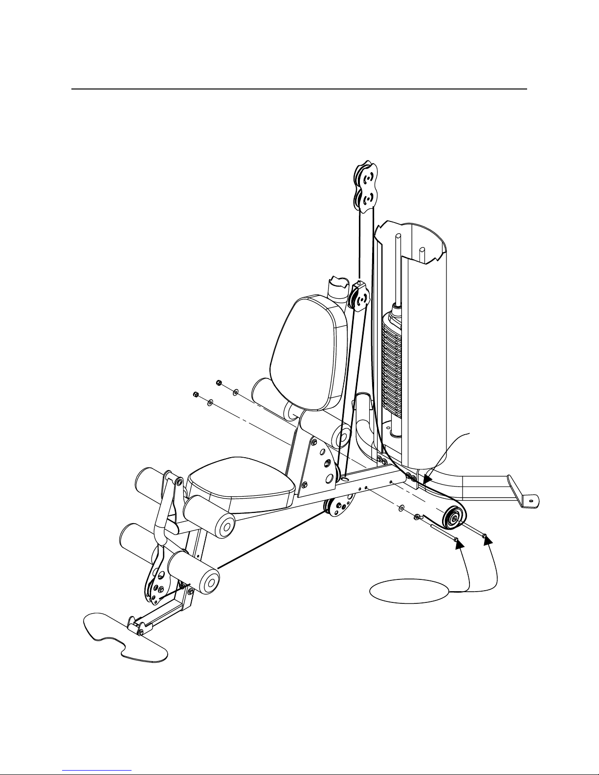
Assembly Procedure for Attaching Leg Press 2 to M4
NOTE: The Leg Press can only be attached to the right side
of the Home Gym.
STEP 1
Floating Pulley
Bracket
Step 1: Disconnect Floating Pulley Bracket from Main Upright and save removed hardware.
Page 12
Page 15

S
STEP 3
2 – 5” Hex Bolts 1 – 4 ¾” Hex Bolt
4 – 3/8” Flat Washers 1 – 3/8” Flat Washer
2 – 3/8” Lock Nuts
Use Upper Holes
Leg Press
Attachment Arm
TEP 2
2 – 1 ¼” Hex Bolts
Leg Press Base
Home Gym
4 – 3/8” Flat Washers
2 – 3/8” Lock Nuts
Step 2: Attach Leg Press Attachment Arm to Home Gym using:
Two (3/8” x 1 ¼” Hex Bolts)
Four (3/8” Flat Washers)
Step 3: Attach Leg Press Base to Leg Press Attachment Arm using:
Two (3/8” x 5” Hex Bolts)
One (4 ¾” Hex Bolt)
Five (3/8” Flat Washers)
(Wrench Tighten Bolts in Steps 2 & 3 Now) Two (3/8” Lock Nuts)
(Finger Tighten Only) Two (3/8” Lock Nuts)
Page 13
Page 16

STEP 4
STEP 5
Pulley-8
1 – 3 ½” Pulley 1 – 3 ½” Pulley
1 – 2” Hex Bolt 1 – 2” Hex Bolt
2 – 3/8” Flat Washers 2 – 3/8” Flat Washers
1 – 3/8” Lock Nut 1 – 3/8” Lock Nut
1 – Cable Adapter
Step 4: Attach LP2-M4 Attachment Cable end to Floating Pulley Bracket using:
Step 5: Attach Pulley 8 to Attachment Arm using:
Step 6: Attach Pulley 9 to Floating Dual Pulley Bracket using:
Step 7: Route LP2-M4 Attachment Cable around Pulleys 8 & 9 and attach cable eyelet end to
Step 8: Attach Cable Retainer Bolt to Attachment Arm using:
(Make sure that the cable is routed between pulley 8 and the cable retainer bolt.)
Cable Adapter
Floating Pulley
Bracket
STEP 6
1 – 3 ½” Pulley
1 – 2” Hex Bolt 1 – 2” Hex Bolt
2 – 3/8” Flat Washers 2 – 3/8” Flat Washers
1 – 3/8” Lock Nut 1 – 3/8” Lock Nut
One (3 ½” Pulley) One (Cable Adapter)
One (3/8” x 2” Hex Bolt) Two (3/8” Flat Washers) One (3/8” Lock Nut)
One (3 ½” Pulley) One (3/8” x 2” Hex Bolt)
Two (3/8” Flat Washers) One (3/8” Lock Nut)
One (3 ½” Pulley) One (3/8” x 2” Hex Bolt)
Two (3/8” Flat Washers) One (3/8” Lock Nut)
Attachment Arm (bottom hole) using:
One (3/8” x 2” Hex Bolt) Two (3/8” Flat Washers) One (3/8” Lock Nut)
One (3/8” x 2” Hex Bolt) Two (3/8” Flat Washers) One (3/8” Lock Nut)
Pulley-9
Floating Dual
Pulley Bracket
(Wrench Tighten Bolts in Steps 4-8 Now)
STEP 7
1 – 2” Hex Bolt
2 – 3/8” Flat Washers
1 – 3/8” Lock Nut
STEP 8
Cable
Retainer
Bolt
Assembly Steps are continued on page 15
Page 14
Page 17

2 – 5” Hex Bolts
STEP 1
Leg Press Base
4 – 3/8” Flat Washers
2 – 3/8” Lock Nuts
Dual Pulley Mount
Press Arms
short end of tube
faces outward
STEP 2
1 – 1/2” x 10 ¾” Hex Bolt
2 – 1/2” Flat Washers
1 – 1/2” Lock Nut
Caution: Press arms are unstable until the
cables are attached. It is recommended to
lay the press arms forward onto a protective
surface until the cables are installed.
Step 1: Attach Dual Pulley Mount to Leg Press Base using:
Two (3/8” x 5” Hex Bolts)
Four (3/8” Flat Washers)
Step 2: Attach Press Arms to Leg Press Base using:
One (1/2” x 10 ¾” Hex Bolt)
Two (1/2” Flat Washers)
One (1/2” Lock Nut)
Note: Leg Press Arms angle outward from Leg Press Frame,
short end of tube faces outward.
(Wrench Tighten Bolts) Two (3/8” Lock Nuts)
(Wrench Tighten Bolts, Assembly Should Move Freely.)
Page 15
Page 18

STEP 5
STEP 6
2 – 3 ½” Pulleys 1 – 3 ½” Pulley
2 – 2” Hex Bolts 1 – 2” Hex Bolt
4 – 3/8” Flat Washers 2 – 3/8” Flat Washers
2 – 3/8” Lock Nuts 1 – 3/8” Lock Nut
1 – 8” Hex Bolt 2 – 3 ½” Pulleys 2 – 3 ½” Pulleys
2 – 3/8” Small OD 2 – 2” Hex Bolts 2 –1 ¾” Hex Bolts
Cable
STEP 7
Cable End
w/ Bushing
Pulley-5 & 6
Pulley-1 & 2
Pulley-7
Pulley-3 & 4
STEP 4 STEP 3
Washers 4 – 3/8” Flat Washers 2 – 3/8” Flat Washers
1 – 3/8” Lock Nuts 2 – 3/8” Lock Nuts
Step 3: Attach Pulleys 1 & 2 to Press Arms using: Two (3 ½” Pulleys)
Two (3/8” x 2” Hex Bolts)
Four (3/8” Flat Washers)
(Wrench Tighten Bolts) Two (3/8” Lock Nuts)
Step 4: Attach Pulleys 3 & 4 to Leg Press Base using: Two (3 ½” Pulleys)
(Wrench Tighten Bolts) Two (3/8” Flat Washers)
Two (3/8” x 1 ¾” Hex Bolts)
Step 5: Attach Pulleys 5 & 6 to Pulley Bracket using: Two (3 ½” Pulleys)
Two (3/8” x 2” Hex Bolts)
Four (3/8” Flat Washers)
Step 6: Attach Pulley 7 to Floating Pulley Bracket using: One (3 ½” Pulley)
(Wrench Tighten Bolts) Two (3/8” Lock Nuts)
One (3/8” x 2” Hex Bolt)
Two (3/8” Flat Washers)
Step 7: Attach Main Cable by sliding end of cable thru slot of Cable End as shown,
then slide Bushing into Cable End, attach Bolt. Route the Main Cable around
Pulleys 1, 3, 5 and thru Floating Pulley 7, continue routing cable around Pulleys 6,
4, 2 and attach other end of cable to Cable End using:
One (3/8” x 8” Hex Bolt)
Two (3/8” Small OD Washers)
(Wrench Tighten Bolts) One (3/8” Lock Nut)
(Wrench Tighten Bolts) One (3/8” Lock Nut)
Page 16
Page 19

STEP 8
Orthopedic Pad
Seat Base
Assembled
Back & Seat Pad
Step 8: Place Orthopedic Pad on Seat Base. Work the edge of pad into the groove
of the Seat base on all sides. Do not use sharp objects during
installation.
Floating Dual
Pulley Bracket
Press Arm Stops Floating Pulley Stop
Step 9:
Screw Press Arm Stops up or down to remove slack in Main Cable, tighten the Jam Nuts.
Make sure both Press Arm Stops are adjusted to the same height; otherwise it might be
difficult to insert the Press Arm Locking Rod later. Next, adjust the Floating Pulley Stop out
until it contacts the Floating Dual Pulley Bracket as shown in the diagram. Tighten jam
nuts on the floating pulley stop. After first weeks use and as needed, adjust cable slack
by alternately adjusting the Floating Pulley Stop and Press Arm Stops.
Cable Adjustment
Page 17
Page 20

STEP 11
Back Pad Stem
2 – 1” Hex Bolts
2 – 3/8” Flat Washers
STEP 10
2 – 2 ½” Hex Bolts
4 – 3/8” Flat Washers
2 – 3/8” Lock Nuts
Back Pad
Handles
Seat Pad
To these sets of holes
Attach Seat & Handle
For more Pre-Stretch
2 – 2 ½” Hex Bolts
STEP 12
2 – 3/8” Flat Washers
To these sets of holes
Attach Seat & Handle
For more Leg Room
Step 10: Attach Handles to Leg Press Base using:
Two (3/8” x 2 ½” Hex Bolts)
Four (3/8” Flat Washers)
(Wrench Tighten Bolts) Two (3/8” Lock Nuts)
Step 11: Attach Back Pad to Back Pad Stem using:
Two (3/8” x 1” Hex Bolts)
(Wrench Tighten Bolts) Two (3/8” Flat Washers)
Step 12: Attach Seat Pad to Leg Press Base using:
Two (3/8” x 2 ½” Hex Bolts)
(Wrench Tighten Bolts) Two (3/8” Flat Washers)
Page 18
Page 21

STEP 14
3/8” Barrel Spacer
4 – 3/8” Barrel Spacers
4 – 1” Button Head Bolts
4 – 3/8” Small OD Washers
4 – 3/8” Thin Lock Nuts
Rubber Bumper Pads
STEP 13
Foot Plates
STEP 15
Press Arms
Step 13: Install Two Adjustable Bumpers.
Step 14: Attach Foot Plates to Press Arms with Rubber Bumper Pads towards top
as follows, tighten bolts first, then install and tighten Thin Lock Nuts using:
Four (3/8” Barrel Spacers)
Four (3/8” x 1” Button Head Bolts)
Four (3/8” Small OD Washers)
Four (3/8” Thin Lock Nuts)
(Tighten Bolts with 6mm Allen Wrench)
Step 15: Foot Plate Stop Adjustment:
To adjust Foot Plate Stop angle, loosen jam nut, screw in or out the
Adjustable Bumper, and retighten the Jam Nut.
Page 19
Page 22

Adj
ustable Bumpers
Locking Rod
Storage
STEP 16
Step 16: Slide Locking Rod thru both Press Arm Brackets and tighten Adjustable
Bumpers against Locking Rod to secure Locking Rod in place.
Store Locking Rod in Leg Press Base as shown when not in use.
Page 20
Page 23

DECAL REFERENCE
714-738-1729
PAGE 21
Page 24

DECAL PLACEMENT
Serial number
label (60 x 40)
On base tube
“WARNING, PINCH
POINTS” between
press pedals, on
leg press arm (60 x
40)
PAGE 22
Page 25

GENERAL MAINTENANCE INFORMATION
Warning: DO NOT place styrofoam or printed materials on the
orthopedic seat pads. Over time, these may stick to the pads and
mar the surface.
Do not leave items sitting on the orthopedic seat pads, these pads
have a special density that takes shape to objects and small objects
will leave imprints in the surface that may take time to come out.
• Periodically inspect the cables, and cable ends, for splitting, cracking or
fraying. Also, watch for bulging or flat areas in the cable.
• Immediately replace cables at the first signs of damage or wear. Never
use equipment with damaged or worn cables.
• Cables naturally stretch over time, so check cable slack periodically and
adjust cable tension as needed.
• Regularly inspect product for loose hardware.
• Do not use or store equipment outdoors.
• Locate and familiarize yourself with all warning decals on the Leg Press.
• Replace damaged or worn Seat Pads immediately.
PAGE 23
Page 26

MAINTENANCE SCHEDULE
ROUTINE
Clean: Seat Pads
Inspect: Cables and
their Fittings
Inspect: All Decals
Inspect: All Nuts and
Bolts. Tighten if Needed
Lubricate: Seat Sleeves
and all Plastic Slides
Clean and Wax: All
Glossy Finishes
HOME
MAINTENANCE
WEEKLY
WEEKLY
3 MONTHS
3 MONTHS
3 MONTHS
YEARLY
ENTRY DATE
Replace: Cables, and
Connecting Parts
2 YEARS
PAGE 24
Page 27

LIMITED WARRANTY
In-Home Lifetime Warranty.
This Warranty applies only in the United States to Inspire strength products manufactured or distributed by Health In
Motion LLC. The warranty period to the original purchaser is lifetime of the original purchaser.
Health In Motion warrants that the Product you have purchased for non-commercial, personal, family or household
use from Health In Motion LLC or from an authorized Health In Motion reseller is free from defects in materials or
workmanship under normal use during the warranty period. Your sales receipt, showing the date of purchase of the
Product, is your proof of the date of purchase. This warranty extends only to you, the original purchaser. It is not
transferable to anyone who subsequently purchases the Product from you. It excludes expendable parts such as paint
and finish. This Warranty becomes VALID ONLY if the Product is assembled / installed according to the instructions /
directions included with the Product.
Replacement and repair of parts.
During the warranty period Health In Motion will at no additional charge, repair or replace the Product if it becomes
defective, malfunctions, or otherwise fails to conform with this Warranty under normal non-commercial, personal,
family, or household use. In repairing the product Health In Motion may replace defective parts with, at the option of
Health In Motion, serviceable used parts that are equivalent to new parts in performance, or new parts. All exchanged
parts and Products replaced under this warranty will become the property of Health In Motion. Health In Motion
reserves the right to change manufacturers and or specification of any part to cover any existing warranty.
Service procedures.
To obtain warranty parts, you must return the parts to Health In Motion or an authorized Health In Motion retailer in
its original container (or equivalent). You must pre-pay any shipping charges, taxes, or any other charges associated
with transportation of the Product. In addition, you are responsible for insuring any Product shipped or returned. You
assume the risk of loss during shipment. You must present Health In Motion with proof-of-purchase documents
(including the date of purchase, Model, and Serial Number). Any evidence of alteration, erasing or forgery of proof of-purchase documents will be cause to void this Warranty.
Conditions and Exceptions.
This Warranty does not extend to any Product not purchased from Health In Motion LLC or from an authorized Health
In Motion reseller. This Warranty does not extend to any Product that has been damaged or rendered defective; (a)
as a result of accident, misuse, or abuse; (b) by the use of parts not manufactured or sold by Health In Motion; (c) by
modification of the Product; (d) as a result of service by anyone other than Health In Motion, or an authorized Health
In Motion warranty service provider; (e) product that has not been properly maintained (follow maintenance schedule
found on product). Should any product submitted for Warranty service be found to be ineligible, an estimate of repair
cost will be furnished and the repair will be made if requested by you upon Health In Motion receipt of payment or
acceptable arrangement of payment.
Disclaimer
EXCEPT AS EXPRESSLY SET FORTH IN THIS WARRANTY HEALTH IN MOTION MAKES NO OTHER WARRANTIES;
EXPRESSED OR IMPLIED INCLUDING ANY IMPLIED WARRANTIES OF MERCHANTABILITY AND FITNESS FOR A
PARTICULAR PURPOSE. HEALTH IN MOTION EXPRESSLY DISCLAIMS ALL WARRANTIES NOT STATED IN THIS
WARRANTY. ANY IMPLIED WARRANTIES THAT MAY BE IMPOSED BY LAW ARE LIMITED TO THE TERMS OF THIS
WARRANTY. NEITHER HEALTH IN MOTION NOR ANY OF ITS AFFILIATES SHALL BE RESPONSIBLE FOR INCIDENTAL
OR CONSEQUENTIAL DAMAGES. HEALTH IN MOTION IS NOT RESPOSIBLE FOR THE REPAIR OR REPLACEMENT OF
ANY PARTS THAT HEALTH IN MOTION DETERMINES HAVE BEEN SUBJECTED AFTER THE DATE OF MANUFACTURE TO
ALTERATION, NEGLECT, ABUSE, MISUSE, NORMAL WEAR & TEAR, ACCIDENT, DAMAGE DURING TRANSIT OR
INSTALLATION, FIRE, FLOOD, OR ANY ACT OF GOD. SOME STATES DO NOT ALLOW LIMITATIONS ON HOW LONG AN
IMPLIED WARRANTY LASTS OR THE EXCLUSION OR LIMITATION OF INCIDENTAL OR CONSEQUENTIAL DAMAGES, SO
THE ABOVE LIMITATIONS OR EXCLUSION MAY NOT APPLY TO YOU. This Warranty gives you specific legal rights and
you may also have other rights that may vary from state to state. This is the only express warranty applicable to
Health In Motion’s “Inspire” branded strength products. Health In Motion neither assumes nor authorizes anyone to
assume for it any other express warranty.
PAGE 25
 Loading...