

Inspire Ignite Wireless Installation Manual

What’s in the box
1 x Assembled Room Thermostat consisting of
1 x Room Thermostat
1 x Battery Cover
1 x Wall Mount
1 x Wall Blanking Plate
1 x Assembled Relay Module consisting of
1 x Control Board
1 x Wall Mount
1 X Front Cover
1 x Screw Pack
2 x Batteries
Introduction
The Ignite Wireless series is designed to control a typical domestic central heating system.
The Relay module can switch two independent channels. This would usually be the Central
Heating and the Hot Water.
The central heating channel is switched on and off in response to commands from the
supplied Wireless Thermostat.
The Hot Water channel is switched on and off at the programmed time intervals that the
user sets. (When in Auto Mode)
1
Ignite Wireless Installation Guide Rev 1.0
WARNING Electricity is dangerous. Before commencing work, ensure that you read and understand these
instructions and isolate the relevant circuit. This product should only be installed by a qualified electrician or
heating engineer and should be installed in accordance to BS 7671 (IEE Wiring Regulations), or to another
equivalent standard.

Specifications
Relay Module
Power Supply: 230V~ 50...60Hz, 2.5W (Max)
Switch Type: 2 x SPDT
Switch Rating: 3 Amps Total load on all Channels
Radio Frequency: 2.4 GHz WiFi & 868 MHz
Dimensions: 160 x 100 x 18 mm (35mm including recessed wallmount)
Thermostat
Power Supply: 2 x AA Alkaline Batteries
Controllable Temperature Range: 10 – 30°C
Frost Protection: Programmable from 0.5 - 30°C
Radio Frequency: 868 MHz
Dimensions: 103 x 103 x 45 mm (max)
Radio Signal
Consideration for location of your new system components and the affects that this may
have on the radio signal is extremely important. The signal will travel between units in a
straight line and will degrade both with distance and (much more importantly) objects that it
has to pass through.
The Relay Module uses WiFi, so you need a WiFi signal where the Relay Module is located.
You can use your phone to get a good indication of signal strength, hold this against the wall
where the Relay Module is located.
If you cannot get a good signal, consider using a Wifi Range extender to help boost the
signal around the property.
The Thermostat needs to connect to the Relay Module via its internal low power radio.
Every house is different and this is NOT a gaurantee, but as a guide, the units should be
able to communicate with each other through two single skin brick or stud walls.
If the above is not possible then consider moving one or more of the system components.
Also, the radio can be adversely affected by large metal objects such as your boiler, hot
water cylinder, radiators and mirrors. For best performance, ensure that your units are
placed at least 1 metre away from such objects.
2
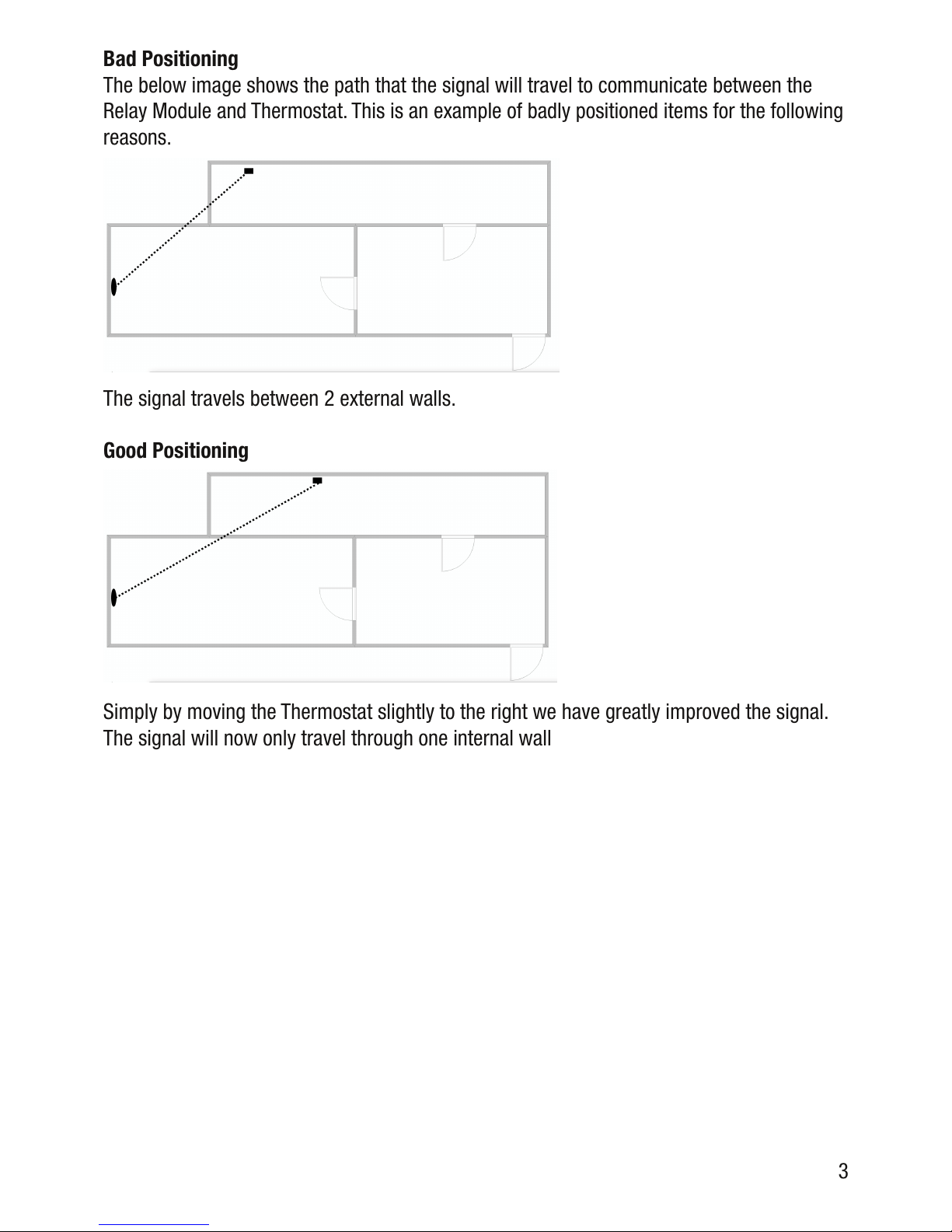
Bad Positioning
The below image shows the path that the signal will travel to communicate between the
Relay Module and Thermostat. This is an example of badly positioned items for the following
reasons.
The signal travels between 2 external walls.
Good Positioning
Simply by moving the Thermostat slightly to the right we have greatly improved the signal.
The signal will now only travel through one internal wall
3
 Loading...