

Page 1
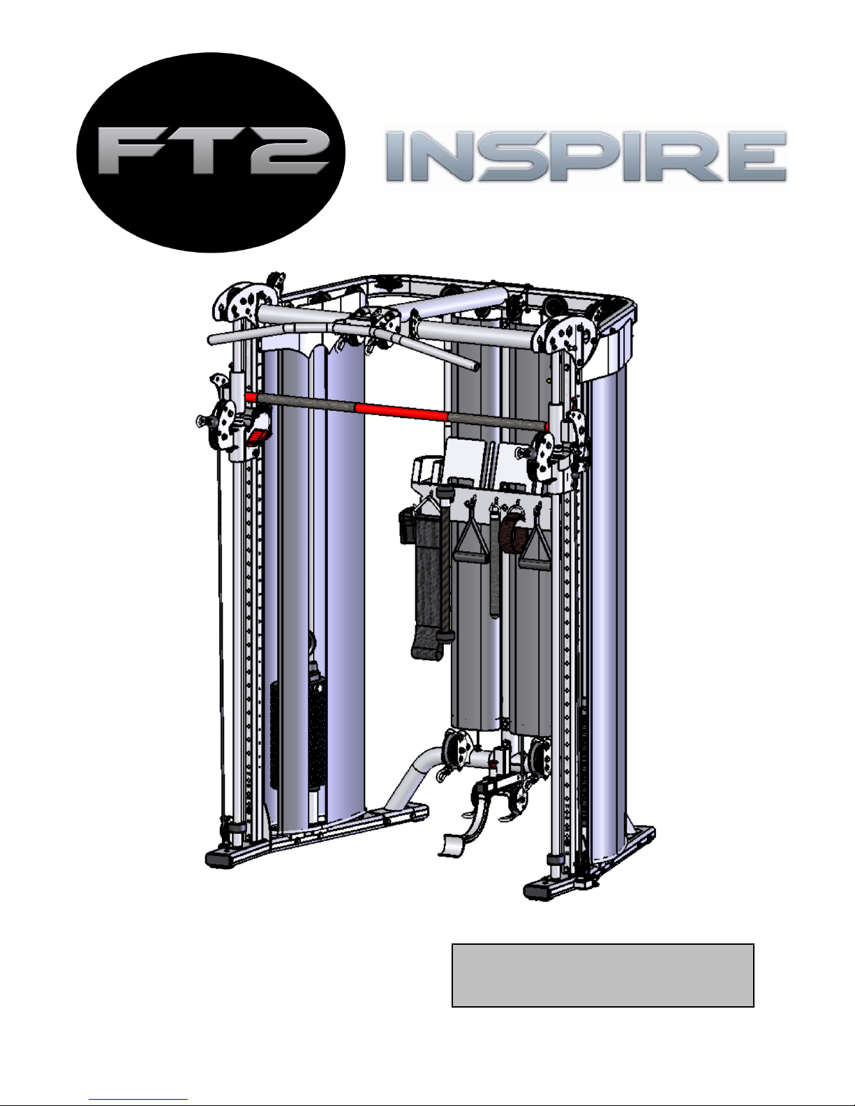
ASSEMBLY & OPERATION MANUAL
RECORD SERIAL NUMBER HER
Page 2

CONGRATULATIONS… You’ve just taken the first step to a healthier
and stronger body. This multi-gym by Inspire offers the key to unlocking
your body’s potential. Regular strength training on a multi-gym has been
shown to deliver a host of benefits including: increased muscle tone,
decreased body fat, improved energy levels, a reduction in stress, and
improved cardiac output. Once again, congratulations, you are on your way
to improving your self image, overall health, and quality of life.
BEFORE ASSEMBLING YOUR HOME GYM
IMPORTANT: Read this entire manual before attempting to build or use
this machine. This manual contains step by step instructions for proper
assembly.
Use the parts list included in this manual to verify that all parts are
accounted for before assembly. If any parts are missing, contact the retailer
of this multi-gym for replacement parts. Or, call Inspire at 877-738-1729.
Make sure that adequate room has been cleared before attempting to build
your multi-gym. A rubber mat is recommended for use under your
multi-gym to protect wood flooring or carpeting from damage during
assembly and usage.
This multi-gym is intended for indoor use only. Rust can form on certain
parts including guide rods in a humid environment, resulting in impaired
function.
Service of your multi-gym should only be preformed by an authorized
Inspire retailer. Service preformed by anyone else can result in loss of
warranty. If you need help finding an authorized retailer, please contact us
directly:
Page 3

TABLE OF CONTENTS
Section Description……………………………………………………. Page
Important Safety Instructions………………………………………. 1
Tools Required………………………………………………………………… 1
Parts & Hardware List……………………………………………………. 2
Exploded View …………………………………………………………………. 3
Cable Chart ……………………………………………………………………. 4
Assembly Instructions……………………………………………………. 5-24
Decal Reference……………………………………………………………… 25
Decal Placement……………………………………………………………… 26
Accessories……………………………………………………………………… 27
General Maintenance Information…….…………………………… 28
Maintenance Schedule…….……………………………………………… 29
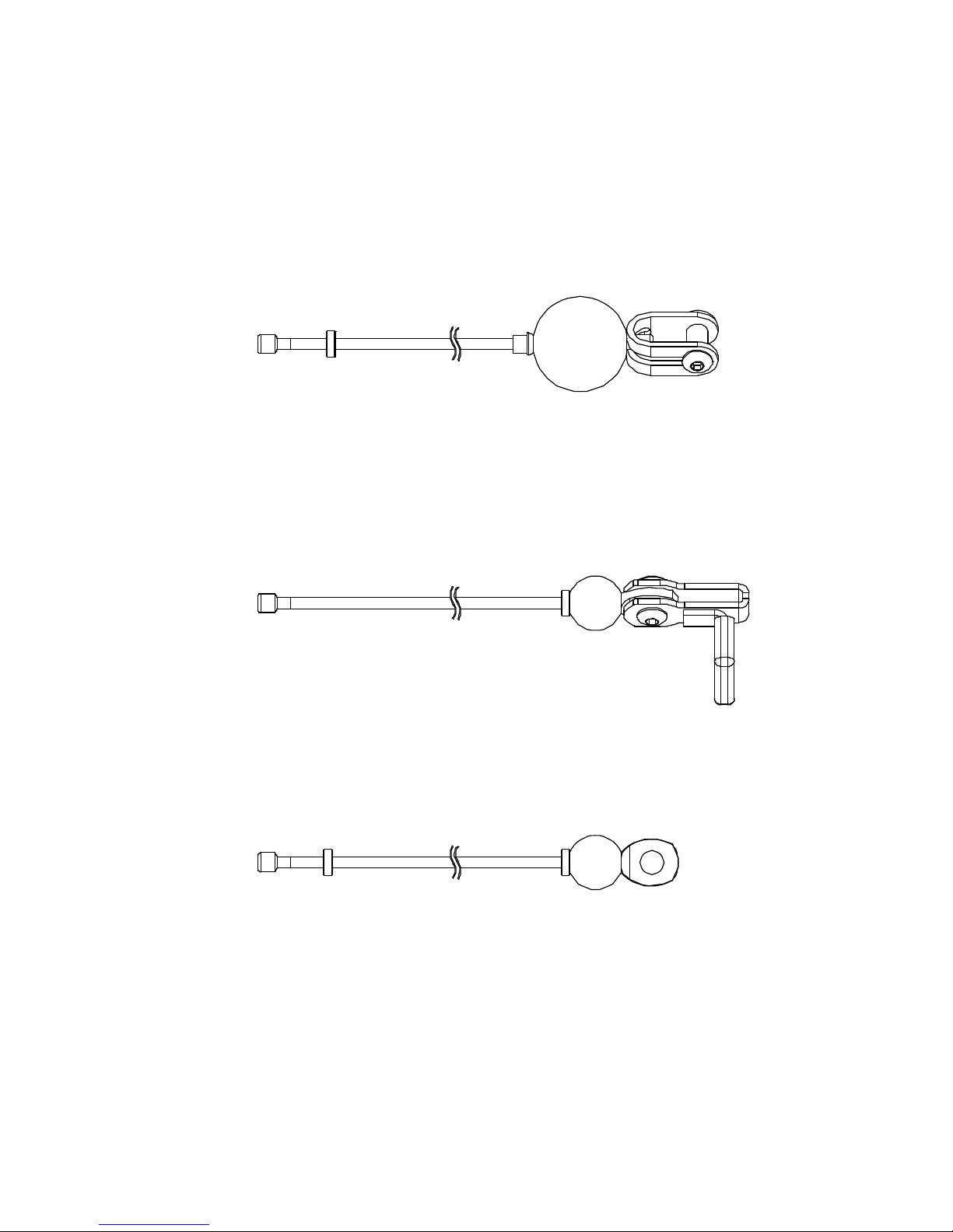
Limited Warranty…………………………………………………………….. 30
Page 4

IMPORTANT SAFETY INSTRUC T IO NS
Please read this entire manual and familiarize yourself with all decals and
warnings before using this multi-gym.
• WARNING! It is necessary to inspect this multi-gym regularly to
maintain safety and proper function. Please use the maintenance schedule
included towards the back of this manual. Immediately replace any and all
defective or worn parts. Pay special attention to moving parts such as the
cables and pulleys and connections to accessories. See General
Maintenance section for complete details.
• Use this multi-gym for its intended purpose as described in this Operation
Manual or the Exercise Book. Do not use attachments not recommended by
the manufacturer.
Do not hang from Weight Bar. The Weight Bar rests on the Right
•
and Left Sliders which are not designed to support human weight.
• Make sure bystanders are at least 5 feet away from the multi-gym while
it is in use.
• Keep children off the multi-gym at all times.
• Keep the multi-gym away from walls and clear of any obstructions and
furniture.
• Stop immediately if you experience shortness of breath, pain, or dizziness
during your workout. Inspire strongly recommends consulting your
doctor before starting an exercise program.
TOOLS REQUIRED FOR ASSEMBLY
• Metric socket set (including 17mm, 18mm, and 19mm sockets)
• Metric 17mm, 18mm, and 19mm wrenches
• 8mm, 6mm, 5mm, and 4mm Allen wrenches (supplied, hardware packs)
• Adjustable wrench
• Tape Measure
• Rubber Mallet
PAGE 1
Page 5

Rev111412
Item
Parts Description Qty
Qty Rec'd
Item
Parts Description Qty
Qty Rec'd
1
Right Base 1
54
"D" Handle
2
2
Left Base 1
55
Slider Adjustment Handle
2
3
Rear Cross Brace 1
56
Pull-up Strap
1
4L
Front Upright, Left 1
57
Ankle Strap
1
4R
Front Upright, Right 1
58
Add-on Weight, 5 Lb
2
5
Rear Upright 1
59
Upper Shroud Mount Bracket, Front 2
6
Rear Pulley Mount 1
60
Upper Shroud Mount Bracket, Left 1
7
Weight Bar 1
61
Upper Shroud Mount Bracket, Right 1
8
Slider, Right 1
62
Upper Shroud Bracket 4
9
Slider, Left 1
63
Rear Shroud Bracket 2
10
Linear Bearing Shaft 2
64
Lower Shroud Bracket 4
11
Spring 2
65
3 1/2" Pulley Assembly 4
12
Linear Bearing Slider, Right 1
66
Metal Shroud, Inner Left 1
13
Linear Bearing Slider, Left 1
67
Metal Shroud, Outer Left 1
14
Front Cross Brace 1
68
Metal Shroud, Inner Right 1
15
Top Beam, Right 1
69
Metal Shroud, Outer Right 1
16
Top Beam, Left 1
70
Fabric Shroud, Outer
2
17
Lat Beam Pivot 1
71
Fabric Shroud, Inner Narrow
2
18
Top Beam Plate Assembly, Left 1
72
Fabric shroud, Inner Wide
2
19
Top Beam Plate Assembly, Right 1
73
Fabric Shroud, Rear
2
20
Lat Beam 1
74
M12 Flat Washer
6
21
Pull-up Bar 1
75
Weight Stack Rubber Donut
4
22
Floating Pulley Assembly
4 76
Slider Rubber Donut 2
23
Top Weight Assembly
2 77
Spring Clip 8
24
Guide Rod
4 78
M10*120 Hex Bolt 6
25
Weight Plate 30
79
M10*80 Socket Head Cap Screw 2
26
Weight Stack Riser
4 80
M10*90 Hex Bolt 6
27
Top Weight Pulley Bracket Assy
2 81
M10*70 Hex Bolt
2
28
Weight Pin 2
82
M10*75 Hex Bolt 6
29
Swivel Pulley Assembly 2
83
M10*80 Hex Bolt 5
30
N/A
84
M8*16 Button Head Bolt 12
31
Cable End Bracket
2 85
M12*85 Hex Bolt 2
32
Lower Cable 2
86
M10*25 Hex Bolt 2
33
Upper Cable 2
87
M10*175 Hex Bolt 1
34
Rear Cable 2
88
M12*30 Hex Bolt 2
35
Guide Cable Assy, Long 2
89
M10*85 Hex Bolt 7
36
Guide Cable Assy, Short 2
90
N/A
37
Slotted Cable Adjustment Bolt 2
91
M10*95 Hex Bolt 2
38
Flat Head Nut, M6*13 2
92
M10*115 Hex Bolt
4
39
M6*8 Button Head Bolt 2
93
M12 Locknut
4
40
M6*15 Button Head Bolt 4
94
M10*20 Button Head Bolt
2
41
Flat Head Nut, M6*25.5 4
95
M6*12 Button Head Bolt
28
42
"U" Bracket Cable End 4
96
M5*10 Philips Head Screw
4
43
Cable Ball 4
97
M10 Flat Washer 74
44
M5*8 Socket Head Cap Screw 2
98
M10 Locknut
45
45
M12 Flange Nut 2
99
M10 Curved Washer
14
46
Bench Stop
1 100
M8 Flat Washer
12
47
Book/Accessory Rack Support 1
101
M6 Flat Washer
28
48
Book/Accessory Rack 1
102
M5 Flat Washer
4
49
Accessory Hanger Bracket 2
103
4mm Allen Wrench
1
50
Revolving Straight Bar
1 104
5mm Allen Wrench
2
51
Revolving EZ Curl Bar
1 105
6mm Allen Wrench
1
52
Sports Handle
1 106
8mm Allen Wrench
1
53
Exercise Rope
1 107
M6*5 Setscrew
4
Parts & Hardware List
PAGE 2
Page 6

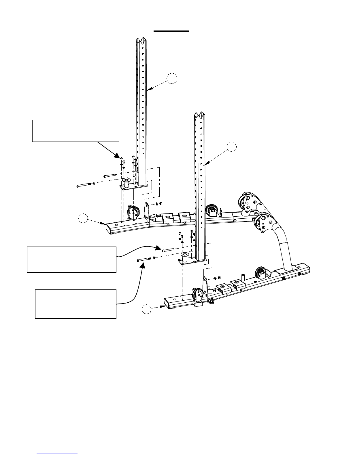
FT2 Exploded View
rev 111412
77
83
1
2
3
4R
65
5
6
7
8
9
10
10
12
102
11
13
14
15
16
17
19
18
20
21
22
22
22
22
23
23
24
24
25
25
26
26
27
27
28
28
31
31
32
33
33
62
34
35
35
36
36
37
37
38
38
39
39
40
40
40
40
98
41
42
42
43
43
43
43
45
45
46
47
48
49
49
50
53
52
56
54
55
51
57
58
58
59
59
60
61
62
62
62
77
63
63
64
64
64
77
66
67
68
69
70
70
71
71
72
72
73
73
55
75
76
78
78
79
79
80
80
65
80
81
81
80
99
91
82
82
95
83
83
84
84
95
95
86
87
92
88
89
89
65
89
65
65
65
65
99
65
65
65
65
65
65
65
89
65
94
95
95
95
95
95
95
95
95
95
84
95
95
95
95
34
95
95
96
96
97
97
65
98
98
99
4L
41
99
99
99
101
101
100
100
98
101
101
101
100
100
84
102
11
82
44
44
98
76
107
107
29
29
93
75
101
83
92
64
PAGE 3
Page 7
Upper Cable
Lower Cable
Rear Cable
CABLE CHART
Cable Number 695-500-002
Cable Number 695-500-001
Cable Number 695-500-003
PAGE 4
Page 8
ASSEMBLY INSTRUCTIONS
PAGE 5
Page 9
STEP 1 Base
4 - M10*120 Hex Bolts (78)
4 – M10 Locknuts (98)
1 2 3
97
98
78
8 – M10 Flat Washers (97)
A) Attach the Rear Cross Brace (3) to the Right and Left Main Bases (1&2) using 4-
M10x120 Hex Bolts (78), 8- M10 washers (97), and 4- M10 Lock Nuts (98).
B) Tighten all the hardware at this time.
Page 6
Page 10
4L
1
4R
2
2 - M10x80 Socket Head (79)
2- M10x90 Hex bolts (80)
8 - M8*16 Button Head (84)
8 - M8 Flat Washers (100)
STEP 2 Front Uprights
2 - M10 Flat washer (97)
2 - M10 Locknut (98)
4 - M10 Flat washer (97)
2 - M10 locknut (98)
A) Attach the Right Front Upright (4R) to the Right Main Base (1) and the Left Front
B) Only finger tighten the hardware at this time. It will be tightened later
Upright (4L) to the Left Main Base (2), using 8- M8x16 Button Head bolts (84)
with 8- M8 washers (100), 2- M10x80 Socket Head Cap Screws (79) with 2-
M10 washers (97) and 2- M10 Lock nuts (98) in the upper hole for the base
flange, 2- M10x90 Hex bolts (80) with 4- M10 washers (97) and 2- M10 Lock
nuts (98) in the lower hole for the base flange.
in Step 7.
Page 7
Page 11

STEP 3 Rear Upright
2 - M10*85 Hex Bolts (89)
2 – M10 Locknuts (98)
1 - M10*80 Hex Bolt (83)
5 6 3
2 – M10 Curved Washers (99)
1 – M10 Locknut (98)
4 – M10 Curved Washers (99)
A) Attach the Rear Upright (5) + the Rear Pulley Mount (6) to the Rear Cross Brace
(3) using 2- M10x85 Hex bolts (89), 4- M10 Curved washers (99), 2- M10 Lock
nuts (98) and 1- M10x80 Hex bolt (83), 2- M10 Curved washers (99) and 1M10 Lock nut (98). The 2- M10x85 Hex bolts (89) might need to be slightly
tightened to be able to insert the M10x80 Hex bolt (83) through the hole in the
Lower Pulley Mount.
B) Only finger tighten the hardware at this time.
Page 8
Page 12

107
76
107
4R
4L
74
29
93
85
74
55
44
29
55
74
44
9
8
85
10
76
74
107
93
107
10
107
76
107
STEP 4 Swivel Pulley Sliders
2-larger ID Slider Rubber Donuts (76)
4 - M6x5 Set screws (107)
2 - M12*85 Hex Bolts (85)
4 – M12 Flat Washers (74)
2 – M12 Locknuts (93)
A) Insert the Linear Bearing Shafts (10) into the collars at the bottom of the Front Uprights (4R & 4L).
Attach these with 4-M6x5 Set screws (107) at the bottom of the collars to hold the Linear Bearing
Shafts (10) in place. Tighten the Set screws now. Slide one (larger ID) Slider Rubber Donut
(76) down each of the Linear Bearing Shafts (10).
B) Attach a Red Slider Adjustment Handle (55) to the shafts on the side of each of the Right and Left
Sliders (8 & 9) with a M5x8 Socket Head Cap Screw (44) in the head of each handle.
C) Note: The Right and Left Sliders (8 & 9) are placed on the Front Uprights (4R&L) and Linear
Bearing Shafts (10) at the same time with the Red handles facing towards the inside of the gym.
This Red handle must be held in the upward position to allow it to be placed on the Front Upright
(4R&L).
Next slide the Right Slider (8) down the Linear Bearing Shaft (10) and Right Front Upright (4R) on
the right hand side of the gym to about the number 20 position on the Upright (4R). Repeat this
step on the left side of the gym using the Left Slider (9) on the Linear Bearing Shaft (10) and the
Left Front Upright (4L).
D) On both Uprights attach the Slider Pulley Swivels (29) to the Sliders (8 & 9) using 2-M12x85 Hex
bolts (85), 4-M12 washers (74) and 2-M12 Lock nuts (93).
Tighten this hardware now but ensure that the swivel moves freely.
PAGE 9
Page 13

10
4R
11
12
11
7
8
13
10
4L
9
STEP 5 Weight Bar
A) Place the Ri g ht and Left Sliders (8&9) (from step 4) at the same number position
on each Front Upright (4R & 4L).
B) Slide a Shock Absorbing Spring (11) over each Linear Bearing Shaft (10) and rest on the
Slider (8&9) as shown.
C) Place the Right and Left Linear Bearing Sliders (12&13) on the Weight Bar (7) as shown.
Carefully lower the Weight Bar (7) down onto the Linear Bearing Shafts (10) being careful
to not damage the Linear Bearings inside the Sliders (12&13). Continue lowering the
Weight Bar (7) down being careful to keep the bar level or it will bind and damage the
Linear Bearings. Rest the Weight Bar (7) with Linear Bearing Sliders (12&13) on the
Springs (11) on top of each Slider (8&9).
PAGE 10
Page 14

STEP 6 Top Beams
4 - M10*90 Hex Bolt (80)
2 - M10*95 Hex Bolt (91)
2 - M10*75 Hex Bolt (82)
15
4R
4 - M10 Flat Washers (97)
2 – M10 Locknuts (98)
17
5
4L
16
8 - M10 Flat Washers (97)
4 – M10 Locknuts (98)
4 - M10 Flat Washers (97)
2 – M10 Locknuts (98)
A) Attach the Right and Left Top Beams (15 & 16) to the Right and Left Front Uprights
(4R & 4L) using 4- M10x90 Hex bolts (80), 8- M10 washers (97) and 4- M10 Lock
nuts (98).
B) Next attach the Right and Left Top Beams (15 & 16) to the Rear Upright (5) and the
Lat Beam Pivot (17) using 2-M10x75 Hex bolts (82), 4- M10 washers (97), 2- M10
Lock nuts (98) in the horizontal holes and 2- M10x95 Hex bolts (91), 4- M10
washers (97), 2- M10 Lock nuts (98) in the longer vertical holes.
Only finger tighten the hardware at this time. It will be fully tightened later in
Step 7.
Tighten the bolts from Step 3 now (bottom of Rear Upright (5)).
PAGE 11
Page 15

15
16
19
14
18
10
10
4R
4L
7
STEP 7 Top Beam Plate Assemblies
4 – M10*75 Hex Bolt (82)
4 – M10 Locknut (98)
2 – M10*70 Hex Bolt (81)
2 – M10 Locknut (98)
Note: The Left Top Beam Plate Assembly (18) (as in using the machi ne with your back
to it) has a Yellow Safety Latch preassembled to it.
A) Attach the Right and Left Top Beam Plate Assemblies (19 & 18) and the Front Cross Brace
(14) to the Front Uprights (4R & 4L) using 4- M10x75 Hex bolts (82), 8- M10 Washers (97)
and 4- M10 Lock nuts (98). Make sure the Yellow Safety Latch is insi de and the 2
preassembled latch bolts stick to the outside on the Top Beam Plate Assemblies (19
& 18). Next attach the Top Beam Plate Assemblies to the Right and Left Top Beams (15 &
16) using 2- M10x70 Hex bolts (81), 4- M10 Washers (97) and 2- M10 Lock nuts (98).
B) Next, lower the Weight Bar (7) to the lowest position by twisting the Weight Bar (7)
and unlatching the Sliders to go down. Twist the Weight Bar (7) to make sure it
rotates freely. If it does not rotate fr eely, adjust the bottom of the Fr o nt Uprights
(4R & 4L) in or out on each Main Base (1 & 2) until it rotates freely. Step on the
Main Base tube and tap the lowe st part of the Front Upright with a rubber mallet to
adjust it. Tighten the lower Fro nt U p right (4R & 4L) bolts from Step 2.
C) Now, raise the Weight bar (7) to the top latch bolts o n the outside Top Beam Plate
Assemblies (19 & 18) and lock it in place by twisting the Weight Bar hook onto the
latch bolts. Swivel the Yellow Safety Latch around the Weight Bar (7). Tighten the
bolts from Step 6 and 7 now.
PAGE 12
4 – M10 Flat Washer (97)
8 – M10 Flat Washer (97)
Page 16

65
65
21
20
2 – M10*25 Hex Bolt (86)
2 – M10 Locknuts (98)
2 – M12*30 Hex Bolt (88)
2 – M12 Locknuts (93)
1 – M10*175 Hex Bolt (87)
1 – M10 Locknut (98)
1 – M10*85 Hex Bolt (89)
Must install these M12
bolts from back to front
17
14
2 – M12 Flat Washers (74)
4 – M10 Flat Washers (97)
2 – M10 Flat Washers (97)
1 – M10 Locknut (98)
A) Attach the Lat Beam (20) to the Lat Beam Pivot (17) and 2 Pulleys (65) using 1-
M10x175 Hex bolt (87), 2- M10 Washers (97) and 1- M10 Lock nut (98).
B) Attach the Lat Beam (20) to the Front Cross Brace (14) using 1- M10x85 Hex bolt
(89), 2- M10 Washers (97) and 1- M10 Lock nut (98). Use the top slot hole in the
flanges and choose a hole in the Lat Beam tube that sets your preferred height of
the Pull-Up Bar (21).
C) Attach the Pull-Up Bar (21) to the Lat Beam (20) using 2- M12x30 Hex bolts (88)
inserted horizontally from the back, 2- M12 Washers (74) and 2- M12 Lock nuts
(93). Then use 2- M10x25 Hex bolts (86) inserted vertically from the top, 4- M10
Washers (97) and 2- M10 Lock nuts (98).
Tighten all the hardware at this time.
STEP 8
2 – M10 Flat Washers (97)
PAGE 13
Page 17

26
23
28
15
27
1 75
24
65
STEP 9 Weight Stacks
2 – M10*115 Hex Bolt (92)
2 – M10 Locknuts (98)
2 – M10*85 Hex Bolt (89)
2 – M10 Locknuts (98)
1 – M10*120 Hex Bolt (78)
1 – M10 Locknuts (98)
25
2 – M10 Flat Washers (97)
4 – M10 Flat Washers (97)
Note: Make sure guide r o d b o l ts ins ert from inside of machine to outside.
A) Attach 2 Guide Rods (24) to the Right Main Base (1) using 2- M10x115 Hex bolts (92), 4-
M10 Washers (97) and 2- M10 Lock nuts (98). Tighten these bolts now.
B) Slide the Weight Stack Risers (26), Rubber Donuts (75) and 15 Weight Plates (25) onto the
Guide Rods (24). Make sure the weight sticker cut out is facing the inside of the machine.
Note: For the optional 215# heavy stac k , D o No t put on the Weight Stack Risers
(26) and put on 20 Weight Plates (25).
C) Screw the Top Weight Pulley Bracket Assembly (27) onto the Selector Stem in the Top
Weight (23). Thread all the way down but do not tighten yet. Make sure the Add On
Weight (58) slides onto the Top Weight easily, if not unscrew the Pulley Bracket
until it fits. Slide the Top Weight assembly (23) onto the Guide Rods (24) so the 4-
1/2”Pulley is positioned between the Guide Rods (24) as shown in detail above.
D) Insert a Weight Pin (28) into the stack.
PAGE 14
4 – M10 Flat Washers (97)
Page 18

26
2
23
27
16
25
28
75
24
65
STEP 9 continued
2 – M10*115 Hex Bolt (92)
2 – M10 Locknuts (98)
2 – M10*85 Hex Bolt (89)
2 – M10 Locknuts (98)
1 – M10*120 Hex Bolt (78)
E) Attach the 2 Guide Rods (24) to the Right Top Beam (15) using 2- M10x85 Hex bolts (89), 4-
M10 Washers (97) and 2- M10 Lock nuts (98), inserted first through the Guide Rods, from
inside to outside. Tighten thes e b o l ts now.
F) Attach a 3-1/2” Pulley (65) to the spacer welded to the Right Top Beam (15) behind the
Guide Rods (24), using 1- M10x120 Hex bolt (78), 2- M10 Washers (97) and 1- M10 Lock nut
(98). Tighten this bolt now.
G) Stick a weight stack sticker (1-16 or 1-21 for heavy stacks) on the Top Weight and the
sticker cut out on each weight plate.
H) Lubricate the Guide Rods (24) with Super Lube or the Lube provided.
Repeat Step 9 on the left side of the machine for the second Weight Stack as shown
below.
4 – M10 Flat Washers (97)
PAGE 15
2 – M10 Flat Washers (97)
1 – M10 Locknuts (98)
4 – M10 Flat Washers (97)
Page 19

41
42 43
40
77
33
695-500-002
Note: Make sure all cables are run between the
retainer pin and the pulley.
Pulley 1
Pulley 3
Pulley 4
Pulley 5
Pulley 6
Pulley 7
Pulley 8
Pulley 9
Pulley 10
Pulley 12
Pulley 11
Pulley 13
Pulley 2
Upper Cable #
Step 10 Upper Cable
A) Route the Upper Cable (33) starting with the small swage end without the ball. Insert
between Pulleys 1&2, go up over Pulley 3, over to Pulley 4 and down under Pulley 5, now
back up and over Pulley 6, then under floating Pulley 7 (next to the tab sticking out from the
Floating Pulley Bracket) of the Floating Pulley Assembly (22), (Make s ur e the tab on the
Floating Pulley Bracket is sticking towards the outside of the machine), now up over
Pulley 8 and back around Pulley 9 and over Pulley 10, next under floating Pulley 11(next to
the tab sticking out from the Floating Pulley Bracket) of the Floating Pulley Assembly, (Make
sure the tab on the Floating Pulley Bracket is sticking towards the back of the
machine), now up over Pulley 12 and out over the lat Pulley 13.
B) Next slide the Cable Ball (43) over the swage of the cable end at Pulley 13 and insert the
swage into the “U” Bracket Cable End (42). Now place a Spring Clip (77) between the “U”
Bracket and insert the Button Head Bolt (40) through the “U” Bracket and Spring Clip into the
Flat Head Nut (41) as shown. Tighten now.
C) Attach a Spring Clip (77) to the other end of this cable at Pulleys 1&2.
D) Repeat this step on the other side of the machine.
STEP 10
PAGE 16
Page 20

STEP 11 Lower Cable
Pulley 14
Pulley 15
Pulley 16
1 - M12 Cable Adjustment Bolt (37)
1 - M12 Flange Nut (45)
32
A) Route the Lower Cable (32) starting with the small swage end without the red tab. Slide
cable under Pulley 14 from front to back and under the Weight Stack Riser slots as shown, to
Pulley 15, go under and up over floating Pulley 16 (Make sure the tab on the flo a ti ng
pulley bracket is sticking towards the outside of the machine), then down to the
threaded riser in the base. Slide the cable into the slot of the Slotted Cable Adjustment Bolt
(37) so that the swage is at the bottom of the bolt. Thread the Flange Nut (45) onto the
Slotted Cable Adjustment Bolt (37) and thread the bolt into the threaded riser on the base at
least 5 full turns. Tighten the Jam nut down to the threaded riser at this time. This
Cable end is used to adjust the cable assembly in step 12.
B) Place the opposite cable end with the red tab over the hook on the carriage as shown.
C) Repeat this step on the other side of the machine.
PAGE 17
Lower Cable # 695-500-001
Page 21

41
40
42
43
77
STEP 12 Rear Cable
Pulley 17
Pulley 18
Pulley 19
695-500-003
Note: Make sure all cables
retainer pin and the pulley.
are run between the
A) Route the Rear Cable (34) starting with the small swage end without the ball stop. Slide
B) Next slide the Cable Ball (43) over the swage of the cable end at Pulley 19 and insert the
C) Attach a Spring Clip (77) to the other end of this cable also.
D) Repeat this step on the other side of the machine.
E) The cable assembly tightness can be adjusted at the lower cables threaded cable
cable under and up behind Pulley 17 from front to back, then over floating Pulley 18 (Make
sure the tab on the floating pulley bracket is sticking towards the back of the
machine) and down around Pulley 19 as shown.
swage into the “U” Bracket Cable End (42). Now place a Spring Clip (77) between the “U”
Bracket Cable End (42) and insert the Button Head Bolt (40) through the “U” Bracket and
Spring Clip into the Flat Head Nut (41) as shown. Tighten now.
ends on the in the bases from step 11. Make sure to tighten the jam nu t after
adjusting.
Rear Cable #
PAGE 18
Page 22

2
36
35
3
15
22
STEP 13 Guide Cables
Rear Guide Cable
(shorter)
Side Guide
Plastic Bushing
(slotted)
A) Thread one end of the Side Guide Cable (35) into the threaded insert in the side/bottom of
the Right Top Beam (15) just above the side floating pulleys (22) for 5 full turns.
B) Thread the other end of the Side Guide Cable (35) into the threaded insert in the Right Main
Base (2) next to the pulley. Thread in until this cable is taught. Tighten the Jam nuts on
both ends to the threaded inse rts now.
C) Repeat for the left side now.
D) Thread one end of the Rear Guide Cable (36) into the threaded insert in the rear/bottom of
the Right Top Beam (15) just above the rear floating pulleys (22) for 5 full turns.
E) Thread the other end of the Rear Guide Cable (36) into the threaded insert in the top of the
Rear Cross Base (3) behind the large pulley. Thread in until this cable is taught. Tighten
the Jam nuts on both ends to the threaded inserts now.
F) Repeat for the left side now.
G) Slide the slot of a plastic bushing around each of the 4 Guide Cables (35 & 36) above the
floating pulleys (22) and insert the bushings into the hole of the tabs sticking out from the
floating pulley brackets until they snap in place. The plastic bushings should be between the
cables and the metal tabs on all 4 Guide Cables.
PAGE 19
Cable (longer)
Page 23

STEP 14 Shroud Mount Brackets
2 – M6*12 Button Head Bolts (95)
2 – M6 Flat Washers (101)
2 – M8*16 Button Head Bolts (84)
2 – M6*12 Button Head Bolts (95)
2 – M6 Flat Washers (101)
Left
(60)
Right
(61)
)
facing to the outside of the machine.
59
16
15
49
49
Front Upper Shroud Mount Bracket (59
Make sure the horizontal rib is
2 – M8 Flat Washers (100)
A) Attach a Front Upper Shroud Mount Bracket (59) (with the horizontal rib facing
towards outside of the machine) to the top back of the Right and Left Front
Upright (4R & 4L) using 2- M6x12 Button Head bolts (95) and 2- M6 washers (101)
on each as shown. Tighten these bolts now.
B) Attach the Left and Right Upper Shroud Mount Brackets (60 & 61) to the Left and
Right Top Beams (16 & 15) using 2-M8x16 Button Head Bolts (84) and 2-M8 washers
(100) on each as shown. Leave loose. These will be tightened in Step 15.
C) Attach an Accessory Hanger Bracket (49) to the bottom/back of both the Left and
Right Top Beams (16 & 15) using 2- M6x12 Button Head bolts (95) and 2- M6
washers (101) on each as shown. Tighten these bolts now.
Bracket
PAGE 20
Bracket
Page 24

62
68
69
62
70
72
71
64
64
1
59
61
4R
STEP 15
Flat section towards
back of machine.
10 - M6*12 Button Head Bolts (95)
4 - M5*10 Philips Head Screws (96)
10 - M6 Flat washers (101)
Step 15, Weight Shrouds
A) Slide one end loop of the Outer Fabric Shroud (70) onto an Upper Shroud Bracket
(62) so the seams face towards weights and the flat section of the Upper
Shroud Bracket is towards the back of the machine. Attach the Upper Shroud
Bracket (62) to the Front Upper Shroud Mount Bracket (59) and lower hole on the
Right Upper Shroud Mount Bracket (61) using 2- M6x12 Button Head bolts (95) and
2- M6 washers (101), one on each side as shown. Leave these bolts loose for
adjustment later.
B) Slide the Lower Shroud Bracket (64) through the loop of the lower end of the Outer
Fabric Shroud (70) so the flange on the Lower Shroud Bracket (64) is towards the
back of the machine. Make sure the seams are on the inside. Slide the front end of
the Lower Shroud Bracket (64) into the insert on the Right Base (1). The other end
latches under the notched flange and attaches with 1- M5x10 Phillips Head Screw
(96) and 1- M5 washer (102). Tighten this screw now.
C) Make sure the outsides of the shroud are straight. Go to the top of the Shroud and
push up on each side of the Upper Shroud Bracket (62) and tighten the bolts (95) in
the bracket while holding the Upper Shroud Bracket up tight to take any slack out of
the shroud. Bolts (95) should be tight now, and the shroud should be taught.
PAGE 21
4 - M5 Flat Washers (102)
Page 25

D) Slide one end loop of the Inner Wide Fabric Shroud (72) and the Inner Narrow Fabric
Shroud (71) onto an Upper Shroud Bracket (62) so the seams face towards
weights, the Narrow Fabric Shroud is to the front, and the flat section of the
Upper Shroud Bracket is towards the back of the Machine. Attach the Upper
Shroud Bracket (62) to the Front Upper Shroud Mount Bracket (59) and lower hole
of the Right Upper Shroud Mount Bracket (61) using 2- M6x12 Button Head bolts (95)
and 2- M6 washers (101), one on each side as shown. Leave these bolts loose for
adjustment later.
E) Slide the Lower Shroud Bracket (64) through the loop of the lower ends of the Inner
Wide Fabric Shroud (72) and the Inner Narrow Fabric Shroud (71) so the flange on
the Lower Shroud Bracket (64) is towards the back of the machine. Make sure the
seams are on the inside. Slide the front end of the Lower Shroud Bracket (64) into
the insert on the Right Base (1). The other end latches under the notched flange and
attaches with 1- M5x10 Phillips Head Screw (96) and 1- M5 washer (102). Tighten
this screw now.
F) Make sure the outer edges of each shroud are straight. Go to the top of the Shrouds
and push up on each side of the Upper Shroud Bracket (62) and tighten the bolts
(95) in the bracket while holding the Upper Shroud Bracket up tight to take any slack
out of the shrouds. Bolts (95) should be tight now, and the shrouds should be
taught.
G) Tighten the bolts in step 14 on the Right Upper Shroud Mount Bracket (61)
to the Right Top Beam (15) Now.
H) Repeat A-G in this step for the left side of the machine.
I) Attach the front of the Outer Right Metal Shroud (69) to the Front Upright (4R) using
2- M6x12 Button Head bolts (95) and 2- M6 washers (101). Attach the rear of the
Outer Right Metal Shroud (69) to the Right Upper Shroud Mount Bracket (61) using
1- M6x12 Button Head bolt (95) and 1- M6 washer (101). Tighten these bolts
now.
J) Attach the front of the Inner Right Metal Shroud (68) to the Front Upright (4R) using
2- M6x12 Button Head bolts (95) and 2- M6 washers (101). Attach the rear of the
Inner Right Metal Shroud (68) to the Right Upper Shroud Mount Bracket (61) using 1M6x12 Button Head bolt (95) and 1- M6 washer (101). The downward arc in the
Inner Metal Shroud should line up with the opening between the Narrow and Wide
Inner Shrouds. Tighten these bolts now.
K) Repeat I-J in this step for the left side of the machine.
PAGE 22
Page 26

63
73
63
73
5
STEP 16 Rear Shrouds
2 – M10*80 Hex Bolts (83)
2 – M10 Locknuts (98)
4 – M10 Curved washers (99)
Step 16, Rear Shrouds
A) Attach the Rear Shroud Brackets (63) to the top and bottom holes in the Rear
Upright (5), using 2-M10x80 Hex bolts (83), 4-M10 Curved Washers (99), and 2-M10
Locknuts (98). Do not tighten these bolts yet.
B) Slide a Rear Fabric Shroud (73) onto each side of the Rear Shroud Brackets (63) as
shown. Align the outer edges of the top and bottom of each Shroud with the inside
and outside edges of the brackets. Next, push the top Rear Shroud Bracket (63) up
to take some slack out of the shroud. Tighten bolt (83) on the upper Bracket
only, now.
C) Next, push down on the bottom Rear Shroud Bracket (63) to tighten the Rear
Shrouds and tighten bolt (83) on the lower Bracket.
D) Bothe bolts (83) should be tight now, and the shrouds should be taught.
PAGE 23
Page 27

48
47
5
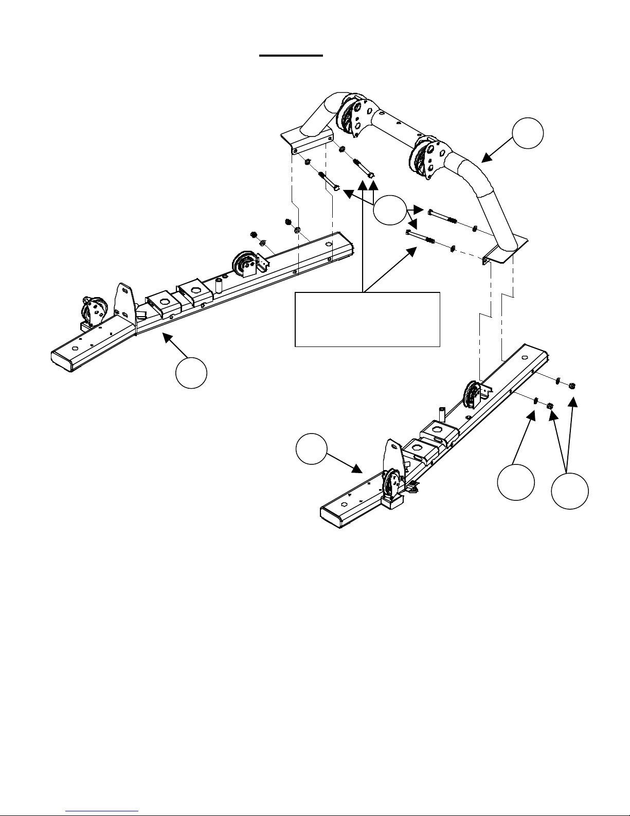
STEP 17 Book/Accessory Rack
2 – M10*20 Button Head Bolts (94)
2 – M10 Locknuts (98)
2 – M10*80 Hex Bolts (83)
2 – M10 Locknuts (98)
4 – M10 Flat Washers (97)
4 – M10 Curved Washers (99)
A) Attach the Book/Accessory Rack Support (47) to the two holes in the middle of the
Rear Upright (5), using 2-M10x80 Hex bolts (83), 4-M10 Curved Washers (99), and
2-M10 Locknuts (98). Tighten these bolts now.
B) Attach the Book/Accessory Rack (48) to the Book/Accessory Rack Support (47) using
2-M10x20 Button Head Bolts (94), 4-M10 Flat Washers (97), and 2-M10 Locknuts
(98). Tighten these bolts now.
PAGE 24
Page 28

DECAL REFERENCE
PAGE 25
Page 29

“FT2” Logo label
(50 x 38)
“
upright. (40 x 170)
“WARNING, PINCH
POINT” (∅20)
“Patent” Label
“NOTICE” Label
Weight # labels (1 –
(18 x 25)
“WARNING, PINCH
POINT” (∅20)
DECAL PLACEMENT
21), included with
manual. Silver #’s on
black background.
WARNING” Label on side of
(50 x 30)
PAGE 26
on side of upright
(40 x 170)
Page 30

ACCESSORIES
• Exercise Book
• Revolving Straight Bar
• Revolving EZ Curl Bar
• Sports Handle
• Exercise Rope
• D Strap Handles (2)
• Pull Up Strap
• Ankle Strap
• 5# Add On Weight (2)
• Water Bottles (2)
MULTI-GYM OPTIONS
• Colored Orthopedic Pads
• Colored Shroud
• Leg Press
• Ab Crunch Bar
Training Tips
CONSULT A PHYSICIAN BEFORE STARTING ANY EXERCISE PROGRAM
1. Always warm up before you start weight training. This helps get
your muscles warm and prevents injury. You can warm up with light
cardio or by doing a light set of each exercise before going to heavier
weights.
2. Control the weight. Always work with a weight that you can handle
through a full range of motion. Slow and steady movements are
recommended.
3. Breathe. Don’t hold your breath during your set. Holding your
breath builds internal pressure which increases your change for broken
blood vessels, as well as a hernia.
4. Sit up straight. Pay attention to your posture and keep everything
straight. Engage your abs in every movement to keep balanced and
protect your spine.
PAGE 27
Page 31

GENERAL MAINTENANCE INFORMATION
• Periodically inspect the cables for splitting, cracking or fraying. Also,
watch for bulging or flat areas in the cable.
• Immediately replace cables at the first signs of damage or wear. Never
use equipment with damaged or worn cables.
• Cables naturally stretch over time, so check cable slack periodically and
adjust cable tension as needed.
• Regularly inspect product for loose hardware.
• Do not use or store equipment outdoors.
• Inspect snap links, swivels, handles, and weight stack pins for wear or
damage. If wear or damage exists, replace immediately.
• Locate and familiarize yourself with all warning decals on the multi-gym.
• Replace damaged or worn upholstery immediately.
• Periodically wipe down guide rods with a dry cloth and re-apply a thin coat
of a teflon-based lubricant.
PAGE 28
Page 32

MAINTENANCE SCHEDULE
Inspect: Links, Pull Pins,
Weight Stack Pins
Clean and Lubricate:
based lubricant
ROUTINE
Spring Clips, Swivels,
Clean: Upholstery
Inspect: Cables and
their Fittings
Inspect: Tautness of all
Shrouds
Inspect: Accessory Bars
and Handles
Inspect: All Decals
HOME
MAINTENANCE
WEEKLY
WEEKLY
WEEKLY
WEEKLY
3 MONTHS
3 MONTHS
ENTRY DATE
Inspect: All Nuts and
Bolts. Tighten if Needed
Inspect: Anti-Skid
surfaces
Guide Rods with a Teflon
Lubricate: Seat Sleeves
and all Plastic Slides
Clean and Wax: All
Glossy Finishes
Replace: Cables, Belts
and Connecting Parts
3 MONTHS
3 MONTHS
3 MONTHS
3 MONTHS
YEARLY
2 YEARS
PAGE 29
Page 33

Warranty.
PAGE 30
This Warranty applies to Inspire Strength products manufactured or distributed by Health In Motion LLC.
CONSUMER USE: LIGHT-COMMERCIAL USE:
LIMITED LIFETIME FRAME: LIMITED LIFETIME FRAME:
Includes Frame and Welds Includes Frame and Welds
LIMITED LIFETIME PARTS: 10 YEAR PARTS:
Includes Upholstery, Hardware, etc. Includes Upholstery, Hardware, etc.
LIMITED LIFETIME MOVING PARTS: 10 YEAR MOVING PARTS:
Includes Pulleys, Cables, etc. Includes Pulleys, Cables, etc.
PLEASE NOTE THAT NOT ALL INSPIRE PRODUCTS ARE MADE FOR LIGHT-COMMER CI AL USE
Refer to your Owner’s Manual or consult with you fitness product dealer to establish if a Product is made for lightcommercial use or not. Using a non-commercial product in a commercial setting can result in serious injury or death!
Health In Motion warrants that the Product you have purchased for light-commercial, personal, family or household
use from Health In Motion LLC or from an authorized Health In Motion reseller is free from defects in materials or
workmanship under normal use during the warranty period. Your sales receipt, showing the date of purchase of the
Product, is your proof of the date of purchase. This warranty extends only to you, the original purchaser. It is not
transferable to anyone who subsequently purchases the Product from you. It excludes expendable parts such as paint
and finish. This Warranty becomes VALID ONLY if the Product is assembled / installed according to the instructions /
directions included with the Product.
Replacement and repair of parts.
During the warranty period Health In Motion will, at no additional charge, repair or replace the Product if it becomes
defective, malfunctions, or otherwise fails to conform with this Warranty under normal light-commercial, personal,
family, or household use. In repairing the product Health In Motion may replace defective parts with, at the option of
Health In Motion, serviceable used parts that are equivalent to new parts in performance, or new parts. All exchanged
parts and Products replaced under this warranty will become the property of Health In Motion. Health In Motion
reserves the right to change manufacturers and or specification of any part to cover any existing warranty.
Service procedures.
To obtain warranty parts, you must return the parts to Health In Motion or an authorized Health In Motion retailer in
its original container (or equivalent). You must pre-pay any shipping charges, taxes, or any other charges associated
with transportation of the Product. In addition, you are responsible for insuring any Product shipped or returned. You
assume the risk of loss during shipment. You must present Health In Motion with proof-of-purchase documents
(including the date of purchase, Model, and Serial Number). Any evidence of alteration, erasing or forgery of proof of-purchase documents will be cause to void this Warranty. Register your warranty online visit www.inspirefitness.net
Conditions and Exceptions.
This Warranty does not extend to any Product not purchased from Health In Motion LLC or from an authorized Health
In Motion reseller. This Warranty does not extend to any Product that has been damaged or rendered defective; (a)
as a result of accident, misuse, or abuse; (b) by the use of parts not manufactured or sold by Health In Motion; (c) by
modification of the Product; (d) as a result of service by anyone other than Health In Motion, or an authorized Health
In Motion warranty service provider; (e) product that has not been properly maintained (follow maintenance schedule
found on product). Should any product submitted for Warranty service be found to be ineligible, an estimate of repair
cost will be furnished and the repair will be made if requested by you upon Health In Motion receipt of payment or
acceptable arrangement of payment.
Disclaimer
EXCEPT AS EXPRESSLY SET FORTH IN THIS WARRANTY HEALTH IN MOTION MAKES NO OTHER WARRANTIES;
EXPRESSED OR IMPLIED INCLUDING ANY IMPLIED WARRANTIES OF MERCHANTABILITY AND FITNESS FOR A
PARTICULAR PURPOSE. HEALTH IN MOTION EXPRESSLY DISCLAIMS ALL WARRANTIES NOT STATED IN THIS
WARRANTY. ANY IMPLIED WARRANTIES THAT MAY BE IMPOSED BY LAW ARE LIMITED TO THE TERMS OF THIS
WARRANTY. NEITHER HEALTH IN MOTION NOR ANY OF ITS AFFILIATES SHALL BE RESPONSIBLE FOR INCIDENTAL
OR CONSEQUENTIAL DAMAGES. HEALTH IN MOTION IS NOT RESPOSIBLE FOR THE REPAIR OR REPLACEMENT OF
ANY PARTS THAT HEALTH IN MOTION DETERMINES HAVE BEEN SUBJECTED AFTER THE DATE OF MANUFACTURE TO
ALTERATION, NEGLECT, ABUSE, MISUSE, NORMAL WEAR & TEAR, ACCIDENT, DAMAGE DURING TRANSIT OR
INSTALLATION, FIRE, FLOOD, OR ANY ACT OF GOD. SOME STATES DO NOT ALLOW LIMITATIONS ON HOW LONG AN
IMPLIED WARRANTY LASTS OR THE EXCLUSION OR LIMITATION OF INCIDENTAL OR CONSEQUENTIAL DAMAGES, SO
THE ABOVE LIMITATIONS OR EXCLUSION MAY NOT APPLY TO YOU. This Warranty gives you specific legal rights and
you may also have other rights that may vary from state to state. This is the only express warranty applicable to
Health In Motion’s “Inspire” branded strength products. Health In Motion neither assumes nor authorizes anyone to
assume for it any other express warranty.
 Loading...