

Page 1

ASSEMBLY & OPERATION MANUAL
RECORD SERIAL NUMBER HERE
www.inspirefitness.net by Health In Motion LLC June 2011
Page 2

TABLE OF CONTENTS
u Section Description………………………………………………….. Page
u Before You Begin…………………………………………………………. 1
u Important Safety Notices……………………………………………. 2
u Tools Requires……………………………………………………………… 2
u
Parts List…………………..………………………………………………….. 3
u Hardware Sizing Chart ………………………………………………… 4
u Assembly Instructions………………………………………………….. 5-16
u Exploded Diagram……………………………………………………….. 17
u General Maintenance Information…….………………………… 18
u Maintenance Schedule…….………………………………………….. 19
u Limited Warranty.………………………….……………………………. 20
BEFORE YOU BEGIN
Read this entire manual before attempting to build or use your gym. This
manual contains step by step instructions for proper assembly.
Use the parts list included in this manual to verify that all parts are
accounted for before assembly. If any parts are missing, contact the retailer
of this home gym for replacement parts. Or, call Inspire at 714 -738-1729
Service of your home gym should only be preformed by an authorized
INSPIRE retailer. Service preformed b y anyone else can result in loss of
warranty. Use only Inspire replacement parts on this machine. The use of
any other brand of parts can also result in a loss of warranty. If you need
help finding an authorized retailer, please contact us directly:
Inspire Fitness
4945 East Hunter Ave.
Anaheim, CA 92807
Ph: 877-738-1729
Fx: 714 -738-1728
www.inspirefitness.net
PAGE 1 6/2011
Page 3

IMPORTANT SAFETY NOTICE
PRECAUTIONS
This exercise machine is built for optimum safety. However, certain
precautions apply whenever you operate a piece of exercise equipment. Be
sure to read the entire manual before you assemble or operate your
machine. In particular, note the following safety precautions:
1. Keep children and pets away from the machine at all times. DO NOT
leave children unattended in the same room with the machine.
2. Only one person at a time should use the machine.
3. If the user experiences dizziness, nausea, chest pain, or any other
abnormal symptoms, STOP the workout at once. Consult a Physician.
4. Position the machine on a clear, leveled surface. Do not use outdoors.
5. Keep hands away from all moving parts.
6. Always wear appropriate workout clothing when exercising. Running
or aerobic shoes are also required when using the machine.
7. Use the machine only for its intended use as described in this manual.
8. Disabled persons should not use the machine without a qualified
person or physician in attendance.
9. Always do stretching exercises to properly warm up before using
machine.
10. Never operate the machine if it is not functioning properly.
11. A spotter is recommended during exercise.
12. Maximum user weight on bench is 300 lbs.
TOOLS REQUIRED FOR ASSEMBLY
Tools Required for Assembling the Machine: Adjustable Wrench and Allen
Wrenches. NOTE: Two or more people assembling this machine is a must.
DO NOT attempt to assemble this machine alone.
PAGE 2 6/2011
Page 4

PARTS LIST
Part#
Description
Q'ty
(pcs)
Part#
Description
Q'ty
(pcs)
1
Right Station Assembly
1
33
Left Inner Logo Plate
1
2
Left Station Assembly
1
34
Shroud Mount Bar
4
3
Upper Frame Assembly
1
35
Hanger Panel
1
4
Lower Cross Brace 1
36
Height Adjustment Handle 2
5
Upper Cross Brace
1
37
Rubber Bumper
4
6
Guide Rod Bracket&Ring Cap
2
38
Plastic Washer
2
7
Guide Rod
4
39
Hook
2
8
Exercise Chart Hanger Bracket 2
40
M6 x 5/8” Allen Bolt 16
9
Exercise Chart Hanger
1
41
M10 x 3 1/8” Allen Bolt
4
10
Selector Stem Assembly
2
42
M10 x 2 ¾” Allen Bolt
8
11
Support Frame for Weight Stack
4
43
M10 x 1” Allen Bolt
4
12
Weight Selector Pin 2
44
M10 x ¾” Allen Bolt 4
13
Weight Plate
30
45
M5 x 3/8” Allen Bolt
2
14
Upper Hanger Bracket
1
46
M8 x ½” Allen Bolt
1
15
Lower Hanger Bracket
1
47
Ø ¾” Lock Washer
8
16
Upper Hanger
1
48
M10 Aircraft Nut
8
17
Middle Hanger
1
49
Ø 7/8” Washer
21
18
Lower Hanger
1
50
Ø 1” Washer
28
19
Middle Hanger Bracket
1
51
Ø ¾” Washer
12
20
Rope
1
52
D-shaped Washer
1
21
Sports Handle
1
53
#6 Allen Wrench (Tool)
1
22
Curl Bar
1
54
#5 Allen Wrench (Tool)
1
23
Straight Bar
1
55
#4 Allen Wrench (Tool)
1
24
Single Handle
2
56
#17 Crossing Wrench (Tool)
1
25
Chin Up Belt
1
57
Flip Exercise Chart
1
26
Ankle Strap
1
58
Resistance Label Set
2
27
Outer Fabric Shroud
2
59
M8 x 5/8” Allen Bolt
20
28
Inner Fabric Shroud
4
60
Ø 2” Tension Adjustment Plate
2
29
Lower Shroud Mount 4
61
Pulley 2
30
Left Outer Logo Plate
1
62
U-shaped Pulley Bracket
2
31
Right Outer Logo Plate
1
63
5LBS Weight Block
2
32
Right Inner Logo Plate
1
PAGE 3 6/2011
Page 5
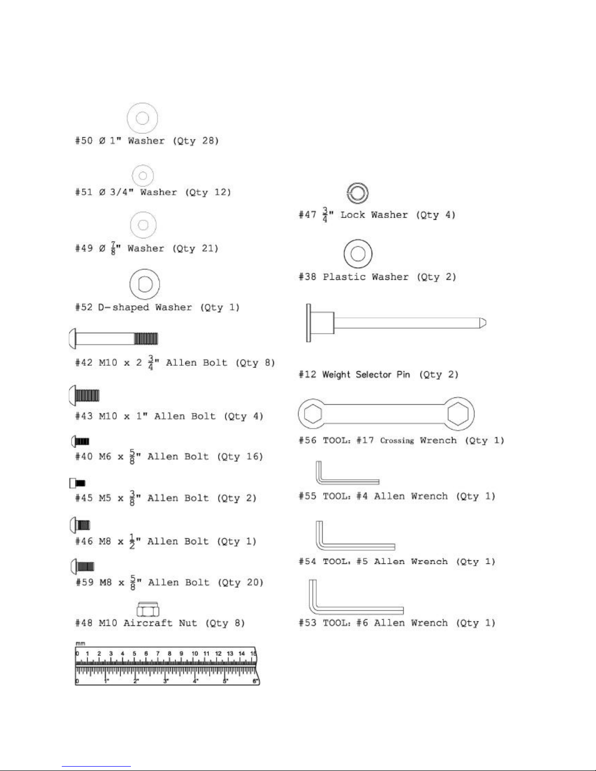
HARDWARE SIZING CHART
PAGE 4 6/2011
Page 6

FUNCTIONAL TRAINER ASSEMBLY INSTRUCTIONS
STEP 1 (See Diagram 1)
A.) Do not tighten the Nuts and Bolts until instructed to do so.
B.) Place the Lower Cross Brace (#4) between the Right & Left
Stations (#1 & #2) in the mid-span.
C.) Attach one end of the Lower Cross Brace to the Right Station.
Secure it with two M10 x 2 ¾” Allen Bolts (#42), four Ø 1” Washers
(#50), and two M10 Aircraft Nuts (#48). Repeat the same
procedure to install the other side.
D.) Repeat Procedure B & C to install the Upper Cross Brace (#5).
E.) Place the Upper Frame (#3) on top of the Right and Left Stations.
F.) Secure each end with two M10 x 1” Allen Bolts (#43), two Ø ¾”
Lock Washers (#47), and
Ø 1” Washers (#50). G.) Securely tighten all Nuts and Bolts
installed
PAGE 5 6/2011
Page 7
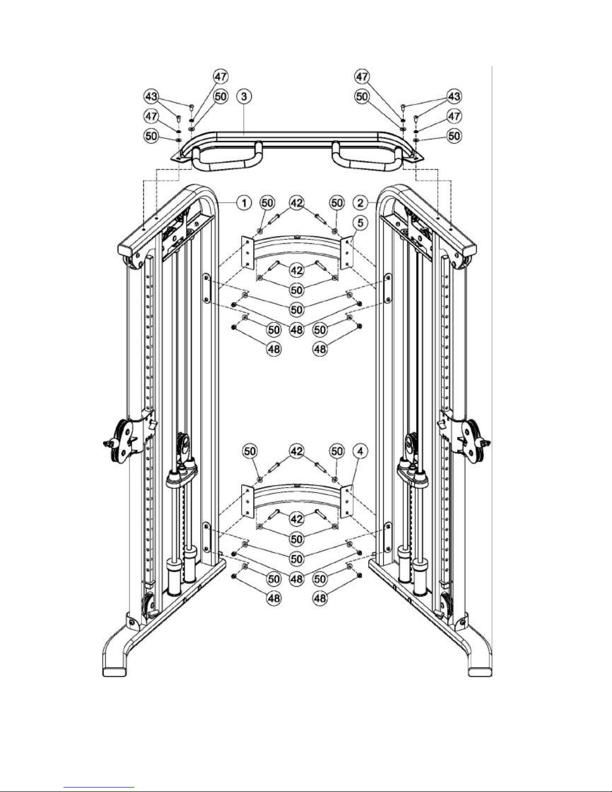
Diagram 1
PAGE 6 6/2011
Page 8

STEP 2 (See Diagram 2)
A.) Lift up the Selector Stem (#10) on the Right Station (#1) and
hold it still to release the tension on the cables. Remove the two
M10 x ¾” Allen Bolts (#44), Ø ¾” Spring Washers (#47), and Ø 1”
Washers (#50) which were pre -assembled in the factory to hold the
Guide Rod Bracket (#6).
B.) Pull the two Guide Rods (#7) away from the Upright. Remove
the Guide Rod Bracket (#6) from the top of the Guide Rods.
C.) Remove the Selector Stem (#19) from the Guide Rods.
D.) Slide fifteen 10lb Weight Plates (#13) from the top of Guide
Rods down to the Rubber Bumpers (#37). Make sure the weight
sticker cut out is facing the inside of the machine.
E.) Slide the Selector Stem back onto the Guide Rods. Hold the
Selector Stem above the weight stack to make it easier to re -install
Guide Rods and Bracket.
F.) Re -install the Guide Rod Bracket (#6) onto the Guide Rods.
G.) Push the Guide Rod Bracket back into the upright.
H.) Secure the Bracket back to the upright frame with the two M10
x ¾” Allen B olts (#44), Ø ¾” Spring Washers (#47), Ø1” Washers
(#50).
I.) Lower the Selector Stem down onto the top of the weight stack.
J.) Check all the cables to make sure they are on track on the
pulleys.
K.) Peel off the weight resistance label from the Resistance Label
Set (#58) and attach to the plates.
L.) Insert the Weight Selector Pin (#12) into the weight stack.
M.) Lubricate the Guide Rods with super lube or lube provided.
N.) If Needed, Adjust the Cable tension by first loosening the M10 x
2” Allen B olt (#10) then rotate the Tension Adjustment Plate (#60)
clock or counterclockwise to move the Bolt and the Large Pulley
(#61) up and down along the open track inside the U -shaped Pulley
Bracket (#6 2). Once desired tension is achieved, securely tighten
the Bolt (#10) back.
O.) Repeat the Procedure A through N above to install the other set
of weight plates to the Left Station (#2).
PAGE 7 6/2011
Page 9

Diagram 2
PAGE 8 6/2011
Page 10

STEP 3 (See Diagram 3)
A.) Slide a Plastic Washer (#38) onto the axle on Upper Hanger
Bracket (#14). Insert the axle through the Upper Cross Brace (#5)
from bottom. Secure it with one M8 x ½” Allen Bolt (#46), one Ø
7/8” Washer (#49), and one D -shaped Washer (#52).
B.) Slide a Plastic Washer (#38) onto the axle on Lower Hanger
Bracket (#15). Insert the axle into the Lower Cross Brace (#4) from
top.
C.) Do not tighten the Bolts until instructed to do so.
D.) Attach the Hanger Panel (#35) to the Upper Hanger Bracket.
Attach the Upper Hanger (#16) to the Hanger Panel. Align the holes.
Secure them together with three M6 x 5/8” Allen Bolts (#40) and Ø
¾” Washer (#47).
E.) Repeat Procedure D to install the Lower Hanger (#18).
F.) Attach the Middle Hanger Bracket (#19) and the Middle Hanger
(#17) to the Hanger Panel from each side. Align the holes. Secure
them together with two M6 x 5/8” Allen Bolts (#40) and Ø ¾”
Washer (#51).
G.)Securely tighten all the Bolts.
PAGE 9 6/2011
Page 11

Diagram 3
PAGE 10 6/2011
Page 12

STEP 4 (See Diagram 4) (Attach Shrouds)
Start on the Right Side of the gym.
A.) Slide two panels of the Inner Fabric Shroud (#28) onto a Shroud
Mount Bar (#34) so the seams face inside. Attach the Shroud
Mount Bar (#34) to the inside upper frame as shown, using two
M8 x5/8” Allen Bolts (#59) and two Ø 7/8” Washers (#49). Please
Note: The ends of the Shroud Mount Bar are slotted. Be sure to
position the bolts in the center of both slots and tighten completely.
B.) Slide a Lower Shroud Mount (#29) through the bottom loops of
the two Inner Fabric Shroud panels (#28) in Step A. Attach the
Lower Shroud Mount (#29) to the gym frame by sliding one end
into the frame insert. The other end latches under the notched
flange and attaches with one M6X5/8” Allen Bolt (#40).
C.) Attach the Right Inner Logo Plate (#32) as shown using three
M8 x5/8” Allen Bolts (#59) and three Ø 7/8” Washers (#49)
D.) Slide the Outer Fabric Shroud (#27) onto a Shroud Mount Bar so
the seams face inside.
(#34) Attach the Shroud Mount Bar (#34) to the outside upper
frame as shown, using two M8x5/8” Allen Bolts. (#59) and two Ø
7/8” Washers (#49). Please Note : The ends of the Shroud Mount
Bar are slotted. Be sure to position the bolts in the center of both
slots and tighten completely.
E.) Slide a Lower Shroud Mount (#29) through the bottom loop of
the Outer Fabric Shroud (#27) in Step D. Attach the Lower Shroud
Mount (#29) to the gym frame by sliding one end into the frame
insert. The other end latches under the notched flange and
attaches with one M6X5/8” Allen Bolt (#40).
F.) Repeat steps A through E to install shrouds to the Left Side of
the gym.
Note: To loosen or tighten the shrouds release the Lower Shroud
Mount (#29) from the gym. Next loosen the two bolts in the Shroud
Mount Bar (#34). Adjust the Shroud Mount Bar (#34) up to tighten
or down to loosen. Once desired position is found, tighten the bolts
that secure the Shroud Mount Bar (#34). Then reattach the Lower
Shroud Mount by following step B.
PAGE 11 6/2011
Page 13

Diagram 4
PAGE 12 6/2011
Page 14

STEP 5 (See Diagram 5)
A.) Attach one Exercise Chart Hanger Bracket (#8) to the Right
Station (#1). Secure it with two M6 x 5/8” Allen Bolts (#40) and Ø
¾” Washers (#51). Do not tighten the Bolts yet.
B.) Slide the Flip Exercise Chart (#57) onto the Exercise Chart
Hanger (#15).
C.) Attach the Hanger (#15) to the Bracket (#8).
D.) Secure the other Bracket (#8) to the Left Station (#2) with two
M6 x 5/8” Allen Bolts (#40) and ؾ” Washers (#51).
E.) Securely tighten all Bolts installed.
F.) Hang the Sports Handle (#21), both 5lb. Add-on Weights (#63),
Chin Up Belt (#25) & Ankle Strap (#26) onto Upper & Middle
Hanger.
PAGE 13 6/2011
Page 15

Diagram 5
PAGE 14 6/2011
Page 16

STEP 6 (See Diagram 6)
A.) Attach the Height Adjustment Handle (#36) to the Right Lock
Switch (#10) on the Pulley Carriage (#8) Not Shown on Diagram.
Secure it with one M5 x 3/8” Allen Bolt (#45). Repeat the same
procedure to install the other side.
B.) Connect the Single Handle (#24) to the Cable (#2) on the Right
Station (#1) with a Spring Clip (#39). Repeat the same procedure
to install the other side.
C.) Replace the Single Handle with the Ankle Strap (#26), o r Sports
Handle (#21) for various Leg Exercises.
D.) Lift up the Height Adjustment Handle (#36) and slide the Pulley
Carriage (#8) along the Pulley Carriage Support Frame to the
selected level. Release the Handle to lock the Pulley Carriage in
position.
E.) Store Curl Bar (#22), Straight Bar (#23), Rope (#20) onto the
Upper and Lower Hanger Bracket (#14) & (#15).
PAGE 15 6/2011
Page 17

Diagram 6
PAGE 16 6/2011
Page 18

PAGE 17 6/2011
Page 19

GENERAL MAINTENANCE INFORMATION
Warning: DO NOT place styrofoam or printed materials on the
orthopedic seat pads. Over time, these may stick to the pads and
mar the surface.
Do not leave items sitting on the orthopedic seat pads, these pads
have a special density that takes shape to objects and small objects
will leave imprints in the surface that may take time to come out.
• Periodically inspect the cables for splitting, cracking or fraying. Also,
watch for bulging or flat areas in the cable.
• Immediately replace cables at the first signs of damage or wear. Never
use equipment with damaged or worn cables.
• Cables naturally stretch over time, so check cable slack periodically and
adjust cable tension as needed.
• Regularly inspect product for loose hardware.
• Do not use or store equipment outdoors.
• Inspect snap links, swivels, handles and weight stack pin for wear or
damage. If wear or damage exists, replace immediately.
• Locate and familiarize yourself with all warning decals on the home gym.
• Replace damaged or worn upholstery immediately.
• Periodically wipe down guide rods with a dry cloth and re- apply a thin coat
of a teflon -based lubricant.
PAGE 18 6/2011
Page 20

MAINTENANCE SCHEDULE
ROUTINE
HOME
MAINTENANCE
ENTRY DATE
Inspect: Links, Pull Pins,
Snap Links, Swivels,
Weight Stack Pins
WEEKLY
Clean: Upholstery WEEKLY
Inspect: Cables and
their Fittings
WEEKLY
Inspect: Tautness of all
Shrouds
WEEKLY
Inspect: Accessory Bars
and Handles
3 MONTHS
Inspect: All Decals 3 MONTHS
Inspect: All Nuts and
Bolts. Tighten if Needed
3 MONTHS
Inspect: Anti-Skid
surfaces
3 MONTHS
Clean and Lubricate:
Guide Rods with a Teflon
based lubricant
3 MONTHS
Lubricate: Seat Sleeves
and all Plastic Slides
3 MONTHS
Clean and Wax: All
Glossy Finishes
YEARLY
Replace: Cables, Belts
and Connecting Parts
2 YEARS
PAGE 19 6/2011
Page 21

LIMITED WARRANTY
In-Home Lifetime Warranty.
This Warranty applies only in the United States to Inspire strength products manufactured or distributed by Health In
Motion LLC. The warranty period to the original purchaser is lifetime of the original purchaser .
Health In Motion warrants that the Product you have purchased for non-commercial, personal, family or household
use from Health In Motion LLC or from an authorized Health In Motion reseller is free from defects in materials or
workmanship under normal us e during the warranty period. Your sales receipt, showing the date of purchase of the
Product, is your proof of the date of purchase. This warranty extends only to you, the original purchaser. It is not
transferable to anyone who subsequently purchases the Product from you. It excludes expendable parts such as paint
and finish. This Warranty becomes VALID ONLY if the Product is assembled / installed according to the instructions /
directions included with the Product.
Replacement and repair of parts.
During the warranty period Health In Motion will at no additional charge, repair or replace the Product if it becomes
defective, malfunctions, or otherwise fails to conform with this Warranty under normal non- commercial, personal,
family, or household use. In repairing the product Health In Motion may replace defective parts with, at the option of
Health In Motion, serviceable used parts that are equivalent to new parts in performance, or new parts. All exchanged
parts and Products replaced under this warranty will become the property of Health In Motion. Health In Motion
reserves the right to change manufacturers and or specification of any part to cover any existing warranty.
Service procedures.
To obtain warranty parts, you must return the parts to Health In Motion or an authorized Health In Motion retailer in
its original container (or equivalent). You must pre- pay any shipping charges, taxes, or any other charges associated
with transportation of the Product. In addition, you are responsible for insuri ng any Product shipped or returned. You
assume the risk of loss during shipment. You must present Health In Motion with proof -of-purchase documents
(including the date of purchase, Model, and Serial Number). Any evidence of alteration, erasing or forger y of proof -
of-purchase documents will be cause to void this Warranty.
Conditions and Exceptions.
This Warranty does not extend to any Product not purchased from Health In Motion LLC or from an authorized Health
In Motion reseller. This Warranty does not extend to any Product that has been damaged or rendered defective; (a)
as a result of accident, misuse, or abuse; (b) by the use of parts not manufactured or sold by Health In Motion; (c) by
modification of the Product; (d) as a result of service by anyone other than Health In Motion, or an authorized Health
In Motion warranty service provider; (e) product that has not been properly maintained (follow maintenance schedule
found on product). Should any product submitted for Warranty service be found to be ineligible, an estimate of repair
cost will be furnished and the repair will be made if requested by you upon Health In Motion receipt of payment or
acceptable arrangement of payment.
Disclaimer
EXCEPT AS EXPRESSLY SET FORTH IN THIS WARRANTY HEALTH IN MOTION MAKES NO OTHER WARRANTIES;
EXPRESSED OR IMPLIED INCLUDING ANY IMPLIED WARRANTIES OF MERCHANTABILITY AND FITNESS FOR A
PARTICULAR PURPOSE. HEALTH IN MOTION EXPRESSLY DISCLAIMS ALL WARRANTIES NOT STATED IN THIS
WARRANTY. ANY IMPLIED WARRANTIES THAT MAY BE IMPOSED BY LAW ARE LIMITED TO THE TERMS OF THIS
WARRANTY. NEITHER HEALTH IN MOTION NOR ANY OF ITS AFFILIATES SHALL BE RESPONSIBLE FOR INCIDENTAL
OR CONSEQUENTIAL DAMAGES. HEALTH IN MOTION IS NOT R ESPOSIBLE FOR THE REPAIR OR REPLACEMENT OF
ANY PARTS THAT HEALTH IN MOTION DETERMINES HAVE BEEN SUBJECTED AFTER THE DATE OF MANUFACTURE TO
ALTERATION, NEGLECT, ABUSE, MISUSE, NORMAL WEAR & TEAR, ACCIDENT, DAMAGE DURING TRANSIT OR
INSTALLATION, FIRE, FLOOD, OR ANY ACT OF GOD. SOME STATES DO NOT ALLOW LIMITATIONS ON HOW LONG AN
IMPLIED WARRANTY LASTS OR THE EXCLUSION OR LIMITATION OF INCIDENTAL OR CONSEQUENTIAL DAMAGES, SO
THE ABOVE LIMITATIONS OR EXCLUSION MAY NOT APPLY TO YOU. This Warranty gives you specific legal rights and
you may also have other rights that may vary from state to state. This is the only express warranty applicable to
Health In Motion’s “Inspire” branded strength products. Health In Motion neither assumes nor authorizes anyone to
assume for it any other express warranty.
PAGE 2 0 6/2011
 Loading...