

Page 1
ASSEMBLY & OPERATION MANUAL
RECORD SERIAL NUMBER HERE
www.inspirefitness.net by Health In Motion LLC Dec 2011
Page 2

CONGRATULATIONS… You’ve just taken the first step to a healthier
and stronger body. This home gym by Inspire offers the key to unlocking
your body’s potential. Regular strength training on a home gym has been
shown to deliver a host of benefits including: increased muscle tone,
decreased body fat, improved energy levels, a reduction in stress, and
improved cardiac output. Once again, congratulations, you are on your way
to improving your self image, overall health and quality of life.
BEFORE ASSEMBLING YOUR HOME GYM
IMPORTANT: Read this entire manual before attempting to build or use
this machine. This manual contains step by step instructions for proper
assembly.
Use the parts list included in this manual to verify that all parts are
accounted for before assembly. If any parts are missing, contact the retailer
of this home gym for replacement parts. Or, call Inspire at 877-738-1729
Make sure that adequate room has been cleared before attempting to build
your home gym. A rubber mat is recommended for use under your home
gym to protect wood flooring or carpeting from damage during assembly
and usage.
This home gym is intended for indoor use only. In addition, garages and
screened in porches are not recommended due to high humidity or dust.
Certain parts including guide rods can form rust in a humid environment,
resulting in impaired function.
Service of your home gym should only be preformed by an authorized
INSPIRE retailer. Service preformed by anyone else can result in loss of
warranty. If you need help finding an authorized retailer, please contact us
directly:
Inspire Fitness
4945 East Hunter Avenue
Anaheim, CA 92807
Ph: 877-738-1729
Fx: 714-738-1728
www.inspirefitness.net
Page 3

TABLE OF CONTENTS
Section Description……………………………………………………. Page
Important Safety Instructions………………………………………. 1
Tools Required………………………………………………………………… 1
Parts & Hardware List……………………………………………………. 2
Assembly Instructions………………………………………………..…. 3-20
Final Adjustments…………………………………………………………… 21
Decal Reference……………………………………………………………… 22-23
Accessories……………………………………………………………………… 24
General Maintenance Information…….…………………………… 25
Maintenance Schedule…….……………………………………………… 26
Limited Warranty…………………………………………………………….. 27
Page 4

IMPORTANT SAFETY INSTRUCTIONS
Please read this entire manual and familiarize yourself with all decals and
warnings before using this home gym.
• WARNING! It is necessary to inspect this home gym regularly to
maintain safety and proper function. Please use the maintenance schedule
included towards the back of this manual. Immediately replace any and all
defective or worn parts. Pay special attention to moving parts such as the
cables and pulleys and connections to accessories. See General
Maintenance section for complete details.
• Use this home gym for its intended purpose as described in this Operation
Manual or the exercise chart. Do not use attachments not recommended by
the manufacturer.
• Do not hang from press arm. The press arm is not designed to
support human weight.
• Make sure bystanders are at least 5 feet away from the home gym while
it is in use.
• Keep children off the home gym at all times.
• Keep the home gym away from walls and clear of any obstructions and
furniture.
• Stop immediately if you experience shortness of breath, pain, or dizziness
during your workout. Inspire strongly recommends consulting your doctor
before starting an exercise program.
TOOLS REQUIRED FOR ASSEMBLY
• Metric socket set (including 16mm, 17mm, 18mm, 19mm, and 24mm
sockets)
• 16mm, 17mm, 18mm, 19mm, and 24mm wrenches
• Adjustable wrench
• Tape Measure
• Rubber Mallet
PAGE 1
Page 5

PARTS & HARDWARE LIST
Part # Parts Description Q'ty
1 Front Foot Assembly 1 77
2
Base Frame Assembly
3 Rear Foot Assembly 1 81
4 Shroud Mount Rod, Lower 2 82
5 Shroud Mount Bracket, Upper 1 83
6 Weight Selector Tube 1 85
7 Slider Assembly 1 86
8 Lower Arm 2 87
9 Upper Arm 2 88
10 Upper Main Frame Assembly 1 89 Hex Bolt, M12*80 1
11 Lower Main Frame Assembly 1 90
13 Top Beam Plate 2 93
14 Press Arm Mount 1 94
16 Press Arm Mount Cover Plate 1 97
17 Lat Bar 1 98
18 Press Arm Assembly 1 99
20 Backpad Tilt Frame 1 100 Flat Head Nut, φ17*25.5*M6 2
21 Roller Tube 3 102
22 Pulley Bracket, Cable Tensioner 1 103
23 Seat Stem 1 106
24 Leg Extension Assembly 1 107
25 Revolving Straight Bar 1 108
26 Chain 1 111 Flat washer, Φ40*Φ16.5*2.5 8
37 Pulley Assembly, Φ3 1/2" 11 112 Arc Washer, Φ10 16
38L Shroud, Left 1 116
38R Shroud, Right 1 117
40 Step Bushing, Φ12 ID 8 118
43 Large Plastic Washer 2 120
44 Foam Roller 6 121
45 Endcap, Roller Tube 6 122
47 Pop-Pin Shaft, 140 long 1 123
50 Lat Bar Holder 2
51 Barrel Spacer, 1" Long 6
52 Spacer Tube, 3" long 1
53 Seat Pad 2
65 Foot Plate Assembly 1
68
Cable Assembly
69 Cable Ball 2
70 "U" Bracket, Cable End 2
73 Spring Clip 3
74
Adjustable Bumper
Qty Rec'd
1 79
1
4
Part# Hardware Description Q'ty
Hex Bolt, M12*160
Hex Bolt, M16*230
Hex Bolt, M10*70
Hex Bolt, M12*90
Hex Bolt, M10*60
Hex Bolt, M10*115
Hex Bolt, M10*100
Hex Bolt, M10*40
Hex Bolt, M12*100
Button Head Screw, M6*12
Button Head Screw, M6*75
Button Head Screw, M6*15
Button Head Screw, M10*90
Setscrew, M6*8
Flathead Nut, φ17*23*M6
Flat Head Screw, M10*15
Philips Head Screw, M5*12
Cap Screw, M5*10
Flat washer, Φ10
Flat washer, Φ12
Lock Nut, M10
Lock Nut, M12
Lock Nut, M16
Allen Wrench, 3mm
Allen Wrench, 4mm
4-Way Po Plug Wrench, 5mm
Allen Wrench, 6mm
1
4
6
1
3
1
5
2
1
4
1
2
4
2
1
2
1
1
24
8
19
4
4
1
1
1
1
Qty Rec'd
PAGE 2
Page 6
ASSEMBLY INSTRUCTIONS
PAGE 3
Page 7
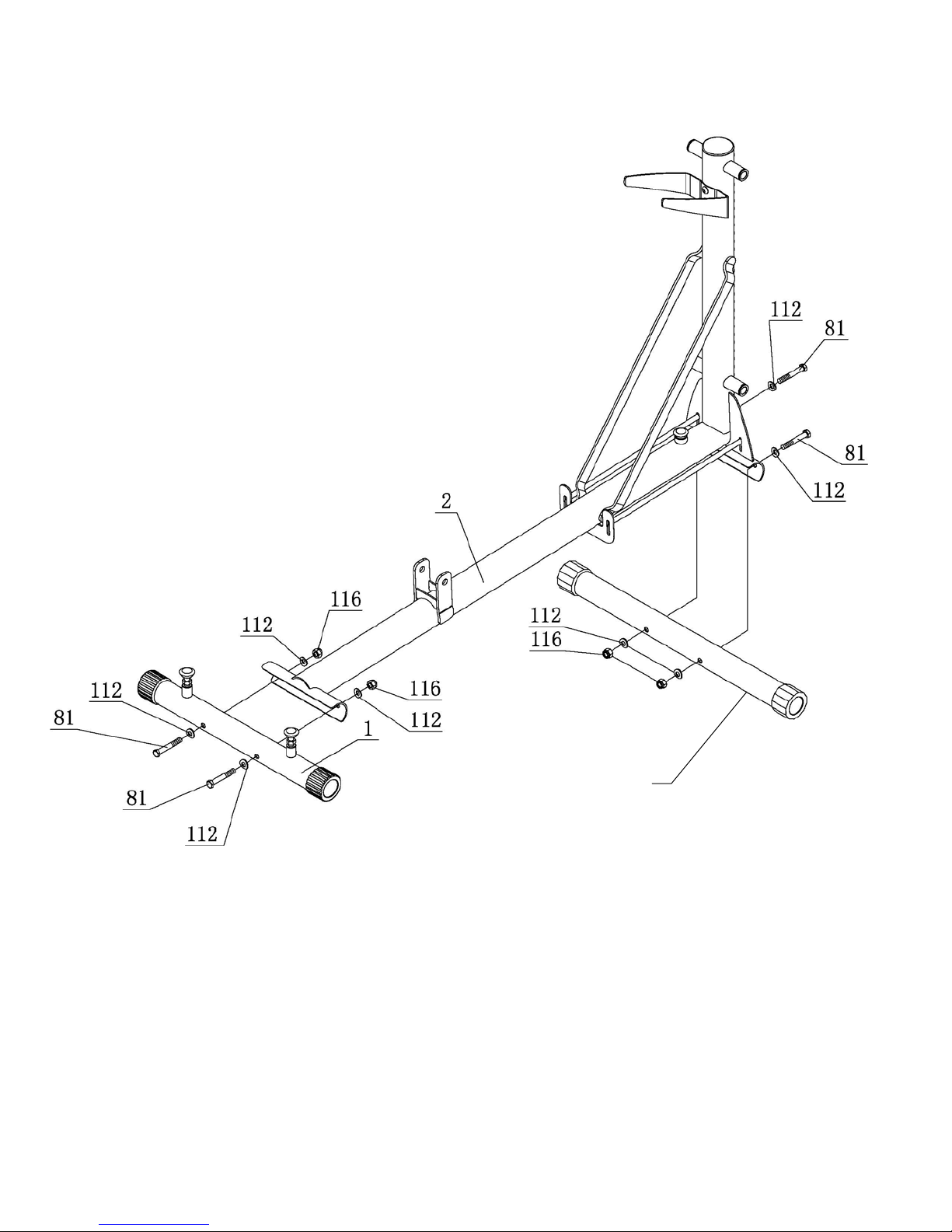
STEP 1
Attach Front Foot Assembly (#1) to Base Frame Assembly (#2) using: Two (M10x70 Bolts)
Attach Rear Foot Assembly (#3) to Base Frame Assembly (#2) using: Two (M10x70 Bolts)
Wrench tighten all bolts now.
3
Page 4 5/11
Page 8
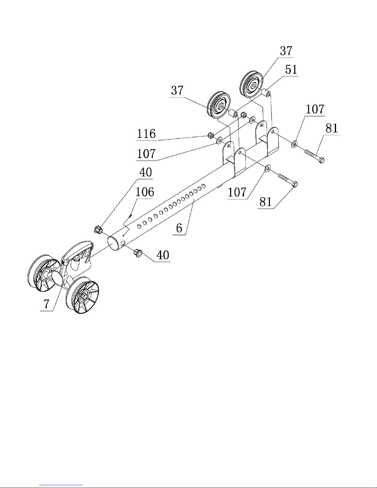
STEP 2
Attach Slider Assembly (#7) to Weight Selector Tube(#6).
Install M5x10 Screw (#106) into Weight Selector Stem (#6) and tighten.
Insert two Step Bushings (#40) into the Weight Selector Tube (#6).
Attach two 3 ½” Pulleys (#37) and two 1” long Barrel Spacers (#51)
to Weight Selector Tube (#6) using:
Two (M10x70 Bolts)
Wrench Tighten Bolts Now.
Page 5 12/11
Page 9
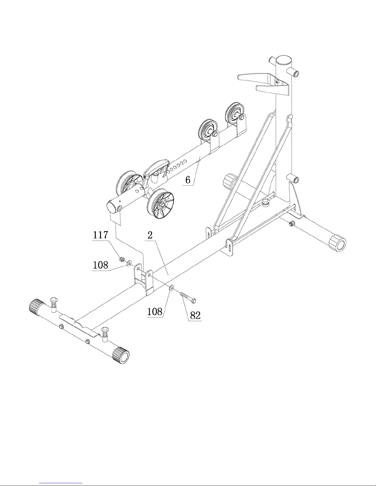
STEP 3
Attach Weight Selector Tube (#6) to Base Frame Assembly (#2) using:
One (M12x90 Bolt)
Wrench tighten bolt so there is a slight drag when moving Weight Selector
Tube. Do not over tighten.
Page 6 12/11
Page 10

STEP 4
Attach Lower Arms (#8) to Base Frame Assembly (#2) using: One (M16x230 Hex Bolt)
Attach Upper Arms (#9) to Base Frame Assembly (#2) using: One (M16x230 Hex Bolt)
Wrench Tighten bolts so there is a slight drag on the Arms when moved.
Do not over tighten.
Page 7 12/11
Page 11

STEP 5
11
65
Attach Lower Main Frame (#11) to Foot Plate (#65) using: Three (M10x60 Hex Bolt)
Wrench Tighten Now.
Page 8 5/11
Page 12

11
STEP 6
8
8
Attach Lower Main Frame (#11) to Lower Arms (#8) using: One (M16x230 Hex Bolt)
Wrench Tighten bolt so there is a slight drag when moving Lower Main Frame.
Do not over tighten .
Page 9 12/11
Page 13

STEP 7
11
Attach Upper Main Frame (#10) to Lower Main Frame (#11) using:
Four (M10*90 Allen Head Screws)
Attach Upper Main Frame (#10) to Left & Right Upper Arms (#8 & #9) using:
One (M16*230 Hex Bolt)
Wrench tighten bolts now.
Page 10 5/11
9
9
Page 14

STEP 8
Attach Top Beam Plates (#13) and One 3 ½” Pulley (#37) to Upper Main Frame (#10) using:
Four (M10*100 Hex Bolts)
Two (1” Long barrel Spacers)
Finger Tighten Only
Attach Lat Bar Holders (#50) and One 3 ½” Pulley (#37) to Top Beam Plates (#13) Using:
One (M10*115 Hex Bolt)
One (M10*100 Hex Bolt)
One (3” Spacer Tube)
Two (1” Long barrel Spacers)
Finger tighten bolts only. No not wrench tighten until after step 9.
10
Page 11
12/11
Page 15

STEP 9
117
108
13
108
88
14
10
47
Attach Press Arm Mount (#14) to Top Beam Plates (#13) using: One (M12*100 Hex Bolt)
Wrench Tighten bolt #88 so there is a slight drag when moving Press Arm Mount.
Do not over tighten .
Wrench tighten all bolts installed in Step 8.
Attach Pop-Pin Shaft (#47) to Upper Main Frame (#10)
Thread Completely and Wrench Tighten.
Page 12
12/11
Page 16

STEP 10
18
14
Attach Press Arm (#18) to Press Arm Mount (#14) using: One (M12*160 Hex Bolt)
Wrench Tighten bolt so there is a slight drag when moving Press Arm.
Do not over tighten .
Page 13 12/11
Page 17

STEP 11
14
16
103
117
108
108
89
11
24
Attach Leg Extension Assembly (#24) to Lower Main Frame (#11) using:
One (M12*80 Hex Bolt)
Wrench Tighten bolt so there is a slight drag when moving Leg Extension Assembly.
Do not over tighten .
Attach Press Arm Mount Cover Plate (#16) using: One (M5*12 Philips head Screw)
Wrench Tighten Now.
Page 14 12/11
Page 18

STEP 12
98
10
20
93
44
45
99
44
43
21
43
45
Attach Back Pad Tilt Frame (#20) to Upper Main Frame (#10) using:
One Roller Tube (#21) Two M6*8 Set Screws (#98)
Two Foam Rollers (#44) One M6*75 Button Head Screw (#93)
Two Large Plastic Washers (#43) One M6 Flat Head Nut (#99)
Two End Caps (#45)
Wrench Tighten bolt #93 so there is a slight drag when moving Back Pad tilt Frame.
Do not over tighten .
Note: Tighten the two set screws(#98) completely after Foam Rollers are installed.
Page 15 12/11
Page 19

STEP 13
23
53
20
53
102
107
102
87
107
87
Attach Seat Pad (#53) to Seat Stem (#23) using: Two (M10*40 Hex Bolts)
Wrench Tighten Now.
Slide Seat Stem (#23) into Lower Main Frame (#11)
Attach Back Pad (#53) to Backpad Tilt Frame (#20) using: Two (M10*15 Flat Head Screw s)
Wrench Tighten Now.
Page 16 5/11
Page 20

STEP 14
45
44
45
44
21
21
44
45
44
45
Attach 4 Foam Rollers (#44) to Leg Extension Assembly (#24) & Seat Stem (#23) using:
Two Roller Tubes (#21)
Four End Caps (#45)
Page 17 12/11
Page 21

STEP 15
Pulley 1
Pulley2
94
70
69
Pulley 3
Pulley 4
Pulley 5
Pulley 6
68
73
100
Pulley 8
Pulley 11
Pulley 9
Pulley 7
Pulley 10
Began at the top of the machine and run the cable sequentially from pulley #1 to pulley #11,
as shown in the above drawing. Once complete, finish both cable ends with a plastic ball
(#69), “U” bracket (#70), flat head nut (#100), button head bolt (#94), and a spring clip
(#73). Look back over the cable routing to make sure that the cable is sitting securely in
each pulley.
Note: Wrench tighten “U” bracket hardware at both ends of the cable.
Page 18 5/11
Page 22

STEP 16
38R
5
38L
90
90
4
Attach Left and Right Shrouds (#38L & #38R) by first slipping the top of each Shroud onto the
horns of the upper shroud mount (#5), as shown above. Make sure seams are to the inside.
Next, slide rods (#4) into the bottom of each shroud and attach to frame using:
Four M6*12 Button Head Screws
Note: Be sure to pull the shrouds down taut before tightening the four screws.
Page 19 12/11
Page 23

STEP 17
Attach Lat Bar (#17) to Spring Clip (#73).
Attach Chain (#26) to Spring Clip (#73) on the end of the Cable.
Attach Revolving Curl Bar (#25) to Chain (#26) with Spring Clip (#73).
73
73
25
73
17
26
Page 20 5/11
Page 24

FINAL ADJUSTMENTS AFTER ASSEMBLY
Press Arm Stop
Macro Cable Adjustment
Nut #2
Nut #1
Weight
Selector
Handle
Wooden Platform
Weight Selector Rollers
Front Rubber Bumper
FINAL ADJUSTMENT: (if needed)
Below the seat you will find the weight selector. Grab the weight selector handle and pull the spring
loaded pin. Slide the weight selector from position one to fifteen. The rollers should move freely. If the
weight selector rollers bind between positions 1-8, lift th e wooden platform and adjust the two Front
Rubber Bumpers up slightly. This will ease the pressure on the rollers and allow the weight selector
mechanism to slide freely.
If the Weight Selector Rollers bind between positions 8-15, thread the press arm stop completely into the
frame. This will provide slack in the cable and ease the pressure on the Weight Selector Rollers. If the
Weight Selector Rollers are still binding, loosen nut #1 in the Macro Cable Adjustment drawing above.
Next, adjust nut #2 counter clockwise until the Weight Selector Rollers move freely. Re-tighten nut #1.
NOTE:
The cable on this gym will stretch over time. There are two places to eliminate cable slack. A large
amount of cable slack can be removed by adjusting the pulley upward on the Macro Cable Adjustment.
Start by loosening nut (#1) shown in the Macro Cable Adjustment drawing above. Next, using a wr ench,
turn nut (#2) clockwise until adequate cable slack has been removed. Finish by tightening nut #1 back
up.
To eliminate a small amount of cable slack, adjust the Press Arm Stop counter clockwise. Wrench tighten
Jam Nut.
Page 21
081711
Page 25

DECAL REFERENCE
877-738-1729
PAGE 22
Page 26

DECAL REFERENCE
PAGE 23
Page 27

ACCESSORIES
• Exercise Wall Chart
• Lat Bar
• Revolving Curl Bar
HOME GYM OPTIONS
• D handles
• Aluminum EZ Curl Bar
• Ab Crunch Bar
Training Tips
CONSULT A PHYSICIAN BEFORE STARTING ANY EXERCISE PROGRAM
1. Always warm up before you start weight training. This helps get
your muscles warm and prevents injury. You can warm up with light
cardio or by doing a light set of each exercise before going to heavier
weights.
2. Control the weight. Always work with a weight that you can handle
through a full range of motion. Slow and steady movements are
recommended.
3. Breathe. Don’t hold your breath during your set. Holding your
breath builds internal pressure which increases your change for broken
blood vessels, as well as a hernia.
4. Sit up straight. Pay attention to your posture and keep everything
straight. Engage your abs in every movement to keep balanced and
protect your spine.
PAGE 24
Page 28

GENERAL MAINTENANCE INFORMATION
• Periodically inspect the cables for splitting, cracking or fraying. Also,
watch for bulging or flat areas in the cable.
• Immediately replace cables at the first signs of damage or wear. Never
use equipment with damaged or worn cables.
• Cables naturally stretch over time, so check cable slack periodically and
adjust cable tension as needed.
• Regularly inspect product for loose hardware.
• Do not use or store equipment outdoors.
• Inspect spring clips, swivels and handles for wear or damage. If wear or
damage exists, replace immediately.
• Locate and familiarize yourself with all warning decals on the home gym.
• Replace damaged or worn upholstery immediately.
PAGE 25
Page 29

MAINTENANCE SCHEDULE
ROUTINE
Inspect: Links, Pull Pins,
Spring Clips, Swivels,
Weight Stack Pins
Clean: Upholstery
Inspect: Cables and
their Fittings
Inspect: Tautness of all
Shrouds
Inspect: Accessory Bars
and Handles
Inspect: All Decals
HOME
MAINTENANCE
WEEKLY
WEEKLY
WEEKLY
WEEKLY
3 MONTHS
3 MONTHS
ENTRY DATE
Inspect: All Nuts and
Bolts. Tighten if Needed
Inspect: Anti-Skid
surfaces
Clean and Lubricate:
Guide Rods with a Teflon
based lubricant
Lubricate: Seat Sleeves
and all Plastic Slides
Clean and Wax: All
Glossy Finishes
Replace: Cables, Belts
and Connecting Parts
3 MONTHS
3 MONTHS
3 MONTHS
3 MONTHS
YEARLY
2 YEARS
PAGE 26
Page 30

LIMITED WARRANTY
In-Home Lifetime Warranty.
This Warranty applies only in the United States to Inspire strength products manufactured or distributed by Health In
Motion LLC. The warranty period to the original purchaser is lifetime of the original purchaser.
Health In Motion warrants that the Product you have purchased for non-commercial, personal, family or household
use from Health In Motion LLC or from an authorized Health In Motion reseller is free from defects in materials or
workmanship under normal use during the warranty period. Your sales receipt, showing the date of purchase of the
Product, is your proof of the date of purchase. This warranty extends only to you, the original purchaser. It is not
transferable to anyone who subsequently purchases the Product from you. It excludes expendable parts such as paint
and finish. This Warranty becomes VALID ONLY if the Product is assembled / installed according to the instructions /
directions included with the Product.
Replacement and repair of parts.
During the warranty period Health In Motion will at no additional charge, repair or replace the Product if it becomes
defective, malfunctions, or otherwise fails to conform with this Warranty under normal non-commercial, personal,
family, or household use. In repairing the product Health In Motion may replace defective parts with, at the option of
Health In Motion, serviceable used parts that are equivalent to new parts in performance, or new parts. All exchanged
parts and Products replaced under this warranty will become the property of Health In Motion. Health In Motion
reserves the right to change manufacturers and or specification of any part to cover any existing warranty.
Service procedures.
To obtain warranty parts, you must return the parts to Health In Motion or an authorized Health In Motion retailer in
its original container (or equivalent). You must pre-pay any shipping charges, taxes, or any other charges associated
with transportation of the Product. In addition, you are responsible for insuring any Product shipped or returned. You
assume the risk of loss during shipment. You must present Health In Motion with proof-of-purchase documents
(including the date of purchase, Model, and Serial Number). Any evidence of alteration, erasing or forgery of proof of-purchase documents will be cause to void this Warranty.
Conditions and Exceptions.
This Warranty does not extend to any Product not purchased from Health In Motion LLC or from an authorized Health
In Motion reseller. This Warranty does not extend to any Product that has been damaged or rendered defective; (a)
as a result of accident, misuse, or abuse; (b) by the use of parts not manufactured or sold by Health In Motion; (c) by
modification of the Product; (d) as a result of service by anyone other than Health In Motion, or an authorized Health
In Motion warranty service provider; (e) product that has not been properly maintained (follow maintenance schedule
found on product). Should any product submitted for Warranty service be found to be ineligible, an estimate of repair
cost will be furnished and the repair will be made if requested by you upon Health In Motion receipt of payment or
acceptable arrangement of payment.
Disclaimer
EXCEPT AS EXPRESSLY SET FORTH IN THIS WARRANTY HEALTH IN MOTION MAKES NO OTHER WARRANTIES;
EXPRESSED OR IMPLIED INCLUDING ANY IMPLIED WARRANTIES OF MERCHANTABILITY AND FITNESS FOR A
PARTICULAR PURPOSE. HEALTH IN MOTION EXPRESSLY DISCLAIMS ALL WARRANTIES NOT STATED IN THIS
WARRANTY. ANY IMPLIED WARRANTIES THAT MAY BE IMPOSED BY LAW ARE LIMITED TO THE TERMS OF THIS
WARRANTY. NEITHER HEALTH IN MOTION NOR ANY OF ITS AFFILIATES SHALL BE RESPONSIBLE FOR INCIDENTAL
OR CONSEQUENTIAL DAMAGES. HEALTH IN MOTION IS NOT RESPOSIBLE FOR THE REPAIR OR REPLACEMENT OF
ANY PARTS THAT HEALTH IN MOTION DETERMINES HAVE BEEN SUBJECTED AFTER THE DATE OF MANUFACTURE TO
ALTERATION, NEGLECT, ABUSE, MISUSE, NORMAL WEAR & TEAR, ACCIDENT, DAMAGE DURING TRANSIT OR
INSTALLATION, FIRE, FLOOD, OR ANY ACT OF GOD. SOME STATES DO NOT ALLOW LIMITATIONS ON HOW LONG AN
IMPLIED WARRANTY LASTS OR THE EXCLUSION OR LIMITATION OF INCIDENTAL OR CONSEQUENTIAL DAMAGES, SO
THE ABOVE LIMITATIONS OR EXCLUSION MAY NOT APPLY TO YOU. This Warranty gives you specific legal rights and
you may also have other rights that may vary from state to state. This is the only express warranty applicable to
Health In Motion’s “Inspire” branded strength products. Health In Motion neither assumes nor authorizes anyone to
assume for it any other express warranty.
PAGE 27
 Loading...