

Inspire BL1 Assembly & Operation Manual
ASSEMBLY & OPERATION MANUAL
RECORD SERIAL NUMBER HERE

BEFORE ASSEMBLING YOUR HOME GYM
IMPORTANT: Read this entire manual before attempting to build or use
this machine. This manual contai ns st ep by step instructions for proper
assembly.
Use the parts list included in this manu al to verify that all parts are
accounted for before assembly. If any parts are missing, contact the retailer
of this home gym for replacement parts.
Make sure that adequate room has been cleared befo re attempting to build
your home gym. A rubber mat is recommended for use under your home
gym to protect wood flooring or carpet ing from da mage dur ing ass embly
and usage.
This home gym is intended for indoor use only. In addition, garages and
screened in porches are not recommended due to high humidity or dust .
Certain parts including guide rods can form rust in a humid environment,
resulting in impaired function.
Sweden Head office
Casall Sport AB
Västgötegatan 7
Box 6007
600 06 Norrköping
Sweden
Phone: +46 (0) 11 32 56 00
Fax: +46 (0) 11 32 56 10
info@casall.se

TABLE OF CONTENTS
Section Description……………………………………………………. Page
Important Safety Instructions………………………………………. 1
Tools Required………………………………………………………………… 1
Parts & Hardware List……………………………………………………. 2
Assembly Instructions………………………………………………..…. 3-20
Final Adjustments…………………………………………………………… 21
Accessories……………………………………………………………………… 22
General Maintenance Information…….…………………………… 23
Maintenance Schedule…….……………………………………………… 24

IMPORTANT SAFETY INSTRUCTIONS
Please read this entire manual and familiarize yourself with all decals and
warnings before using this home gym.
• WARNING! It is necessary to inspect this home gym regularly to
maintain safety and proper function. Please use the maintenance schedule
included towards the back of this manual. Immediately replace any and all
defective or worn parts. Pay special attention to moving parts such a s t he
cables and pulleys and connections to accessories. See General
Maintenance section for complete details.
• Use this home gym for its intended purpose as described in this Operation
Manual or the exercise chart. Do n ot use a t t achments not recommended by
the manufacturer.
Do not hang from press arm. The press arm is not designed to
•
support human weight.
• Make sure bystanders are at least 5 feet away from the home gym while
it is in use.
• Keep children off the home gym at all times.
• Keep the home gym away from walls and clear of any obstructions and
furniture.
• Stop immediately if you experience shortness of breath, pain, or dizziness
during your workout. We strongly recommends consulting your doc t or
before starting an exercise program.
TOOLS REQUIRED FOR ASSEMBLY
• Metric socket set (including 16mm, 17mm, 18mm, 19mm, and 24mm
sockets)
• 16mm, 17mm, 18mm, 19mm, and 24mm wrenches
• Adjustable wrench
• Tape Measure
• Rubber Mallet
PAGE 1

PARTS & HARDWARE LIST
Part #
Parts Description
Q'ty
Qty Rec'd
Part#
Hardware Description
Q'ty
Qty Rec'd
1
Front Foot Assembly
1
77
Hex Bolt, M12*160
1
2
Base Frame Assembly
1
79
Hex Bolt, M16*230
4
3
Rear Foot Assembly
1
81
Hex Bolt, M10*70
6
4
Shroud Mount Rod, Lower
2
82
Hex Bolt, M12*90
1
5
Shroud Mount Bracket, Upper
1
83
Hex Bolt, M10*60
3
6
Weight Selector Tube
1
85
Hex Bolt, M10*115
1
7
Slider Assembly
1
86
Hex Bolt, M10*100
5
8
Lower Arm
2
87
Hex Bolt, M10*40
2
9
Upper Arm
2
88
Hex Bolt, M12*100
1
10
Upper Main Frame Assembly
1
89
Hex Bolt, M12*80
1
11
Lower Main Frame Assembly
1
90
Button Head Screw, M6*12
4
13
Top Beam Plate
2
93
Button Head Screw, M6*75
1
14
Press Arm Mount
1
94
Button Head Screw, M6*15
2
16
Press Arm Mount Cover Plate
1
97
Button Head Screw, M10*90
4
17
Lat Bar 1 98
Setscrew, M6*8
2
18
Press Arm Assembly
1
99
Flathead Nut, φ17*23*M6
1
20
Backpad Tilt Frame
1
100
Flat Head Nut, φ17*25.5*M6
2
21
Roller Tube
3
102
Flat Head Screw, M10*15
2
22
Pulley Bracket, Cable Tensioner
1
103
Philips Head Screw, M5*12
1
23
Seat Stem
1
106
Cap Screw, M5*10
1
24
Leg Extension Assembl y
1
107
Flat washer, Φ10
24
25
Revolving Straight Bar
1
108
Flat washer, Φ12
8
26
Chain 1 111
Flat washer, Φ40*Φ16.5*2.5
8
37
Pulley Assembly, Φ3 1/2"
11
112
Arc Washer, Φ10
16
38L
Shroud, Left
1
116
Lock Nut, M10
19
38R
Shroud, Right
1
117
Lock Nut, M12
4
40
Step Bushing, Φ12 ID
8
118
Lock Nut, M16
4
43
Large Plastic Washer
2
120
Allen Wrench, 3mm
1
44
Foam Roller
6
121
Allen Wrench, 4mm
1
45
Endcap, Roller Tube
6
122
4-Way Po Plug Wrench, 5mm
1
47
Pop-Pin Shaft, 140 long
1
123
Allen Wrench, 6mm
1
50
Lat Bar Holder
2
51
Barrel Spacer, 1" Long
6
52
Spacer Tube, 3" long
1
53
Seat Pad
2
65
Foot Plate Assembly
1
68
Cable Assembly
1
69
Cable Ball
2
70
"U" Bracket, Cable End
2
73
Spring Clip
3
74
Adjustable Bumper
4
PAGE 2
ASSEMBLY INSTRUCTIONS
PAGE 3
3
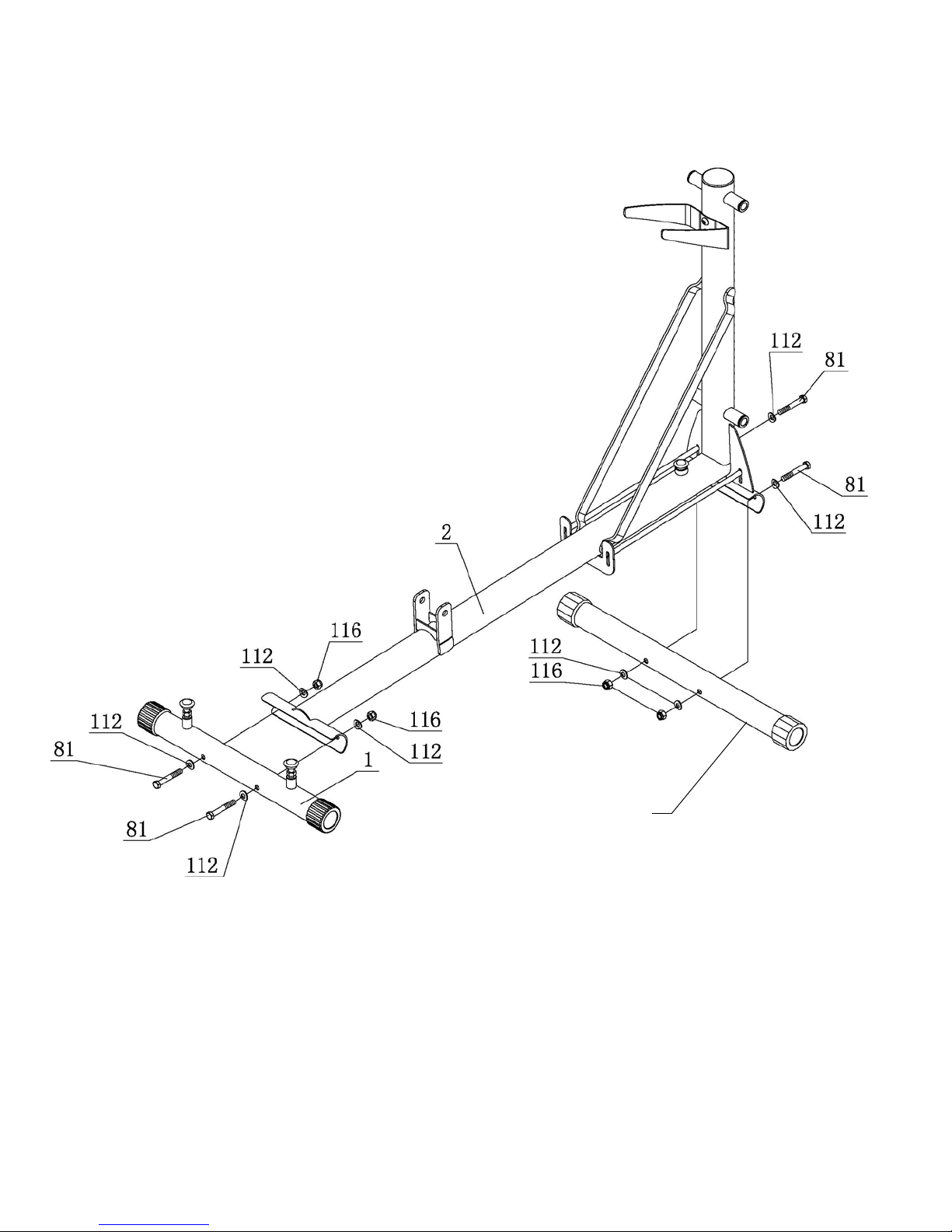
STEP 1
Attach Front Foot Assembly (#1) to Base Frame Assembly (#2) using: Two (M10x70 Bolts)
Attach Rear Foot Assembly (#3) to Base Frame Assembly (#2) using: Two (M10x70 Bolts)
Wrench tig ht en all bolts no w .
Page 4 5/11
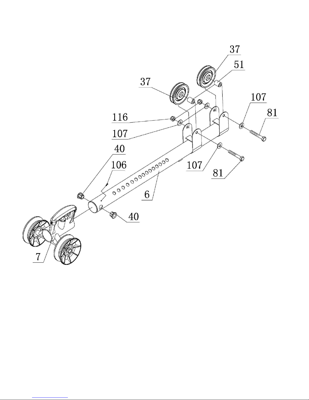
STEP 2
Attach Slider Assembly (#7) to Weight Selector Tube(#6).
Install M5x10 Screw (#106) into Weight Selector Stem (#6) and tighten.
Insert two Step Bushings (#40) into the Weight Selector Tube (#6).
Attach two 3 ½” Pulleys (#37) and two 1” long Barrel Spacers (#51)
to Weight Selector Tube (#6) using:
Two (M10x70 Bolts)
Wrench Tight en Bolts Now.
Page 5 12/11
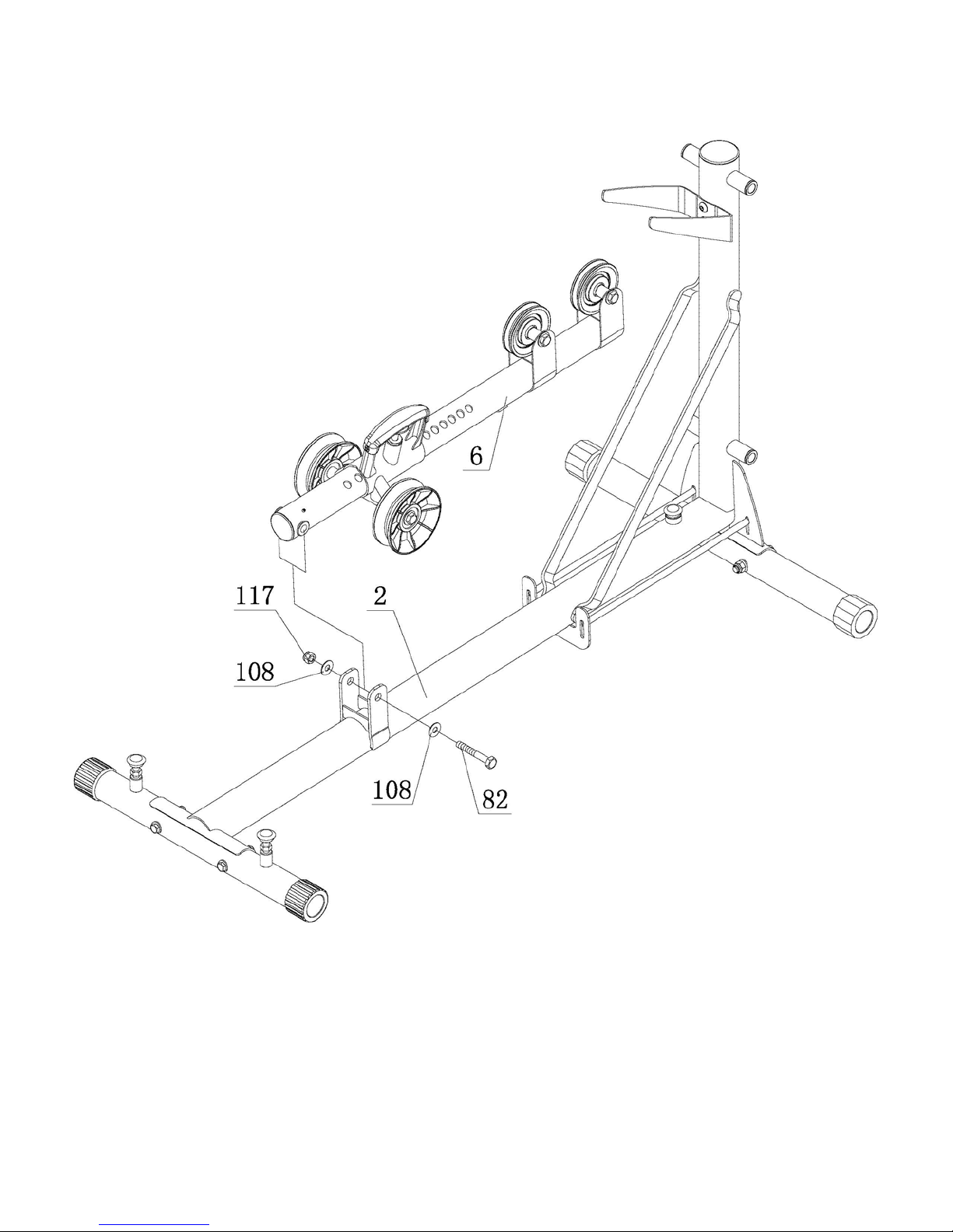
STEP 3
Attach Weight Selector Tube (#6) to Base Frame Assembly (#2) using:
One (M12x90 Bolt)
Wrench tighten bolt so there is a slight drag when moving Weight Selector
Tube. Do not over tighten.
Page 6 12/11
 Loading...