

Page 1

SYSTEM IMPLANT MANUAL
Inspire II Implantable Pulse Generator Model 3024
Stimulation Lead Model 4063
Sensing Lead Model 4323
Rx Only
Page 2

Page 3

Table of Contents
Explanation of Symbols on Product or Package Labeling 5
Indications for Use 7
Therapy Overview 7
Overview of the Manual 8
Sterile Package Contents 8
Implanted Component Descriptions 9
IPG 9
Leads 10
Contraindications 11
Adverse Effects 11
Warnings and Precautions 12
Warnings 12
Precautions 13
Storage and Handling 15
IPG 15
Leads 16
Physician Training 17
System Implant 17
Implantable Components 17
Procedure Overview 18
Patient Preparation 18
Surgical Materials 18
Precautions for Handling Components 18
Stimulation Lead Implant 20
Test Stimulation 22
Securing the Stimulation Lead 23
Making the IPG Pocket 25
Tunneling the Lead 25
Respiratory Sensing Lead Implant 26
Connecting the Leads and IPG 29
Implanting the IPG 32
Completing the Implant Procedure 33
Postoperative Follow-up 33
Physician Instructions to Patient 34
Patient Registration 34
Therapy Activation 34
Therapy Titration 34
Inspire System Models 3024, 4063, 4323 English 3
Page 4

Surgical Revision and Explant 35
Lead Repositioning 35
System or IPG Explant 35
Explant Disposition 35
Clinical Summary 36
Stimulation Therapy for Apnea Reduction (STAR) Clinical Trial 36
Patients Studied 36
Study Design and Methods 37
Study Results 38
IPG Specifications 42
Factory Settings 42
Configurable Settings 43
Battery Information 44
Physical Description 45
Inspire Medical Systems Limited Warranty 46
4 English Inspire System Models 3024, 4063, 4323
Page 5
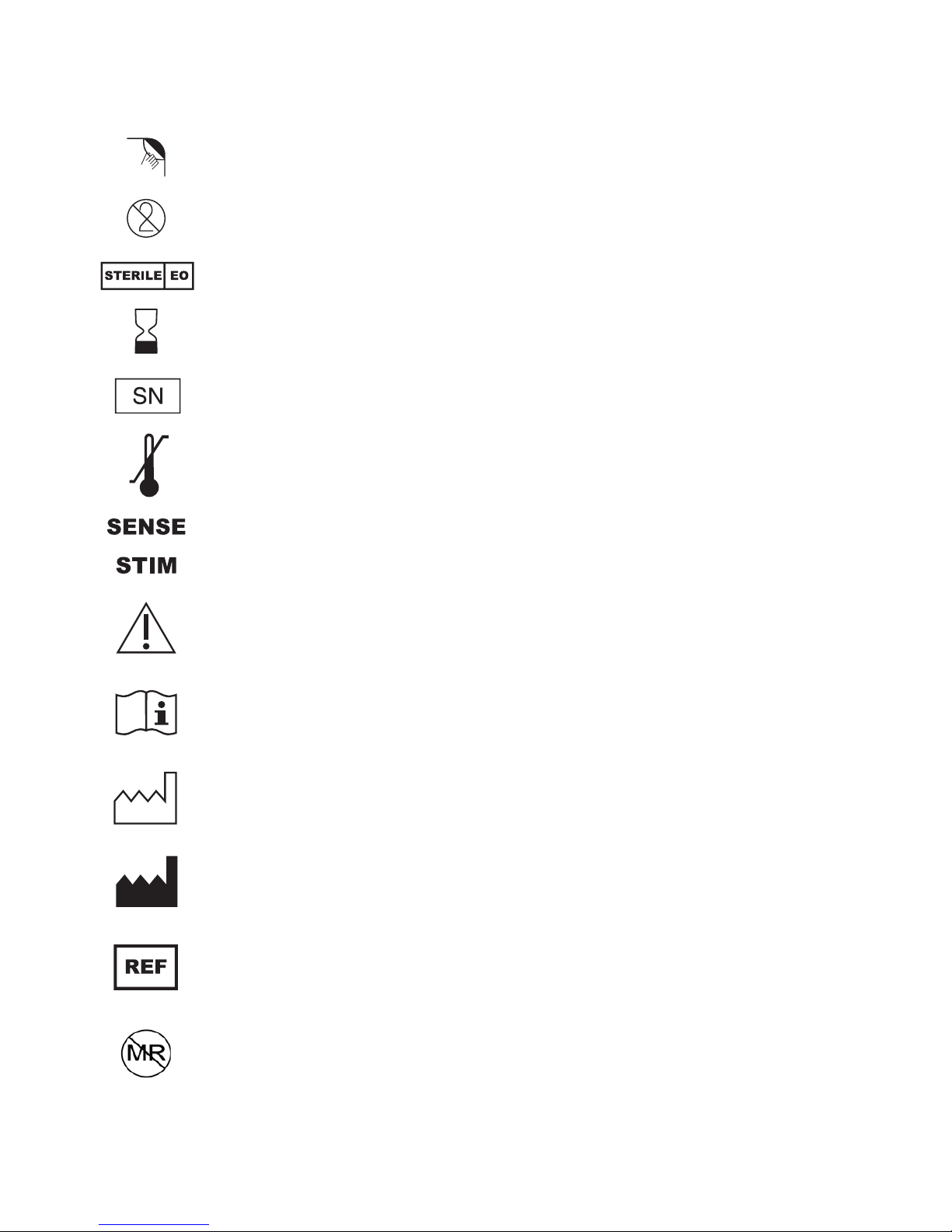
Explanation of Symbols on Product or Package Labeling
Refer to the appropriate product for symbols that apply.
Open here
Do not reuse
Sterilized using ethylene-oxide gas
Use by
Serial number
Temperature limitation
Lead that inserts into SENSE (sensing) port of IPG
Lead that inserts into STIM (stimulation) port of IPG
Caution, consult accompanying documents
Consult instructions for use
Date of manufacture
Manufacturer
Reference number
The Inspire therapy system is MR unsafe
Inspire System Models 3024, 4063, 4323 English 5
Page 6

The following is a trademark of Inspire Medical Systems, Inc.: Inspire
®
6 English Inspire System Models 3024, 4063, 4323
Page 7
Indications for Use
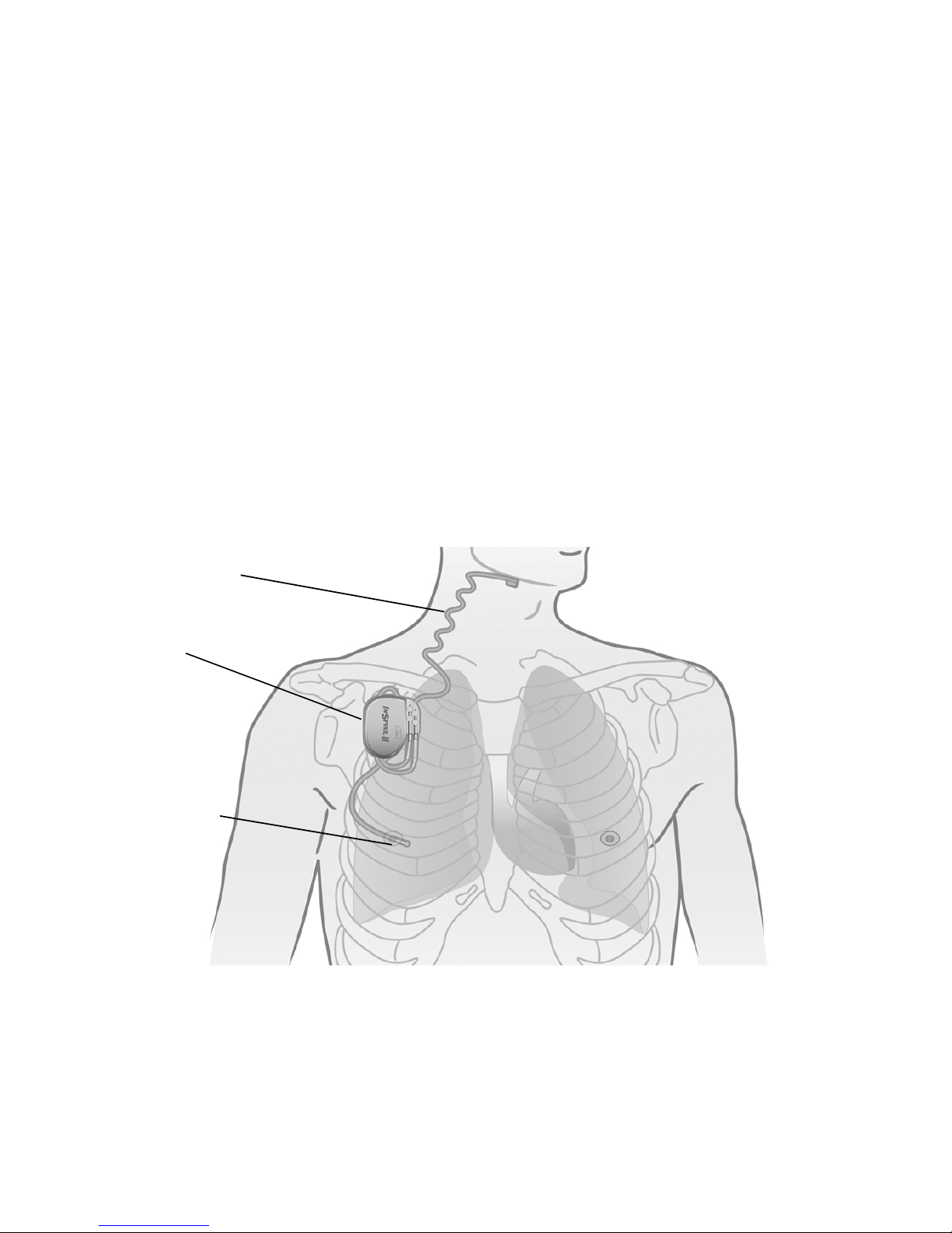
Stimulation lead
Respiratory
sensing lead
Implantable pulse
generator
Inspire Upper Airway
evere obstructive sleep apnea (OSA) (apnea-hypopnea index [AHI] of greater than or equal to
s
15 and less than or equal to 65). Inspire UAS is used in adult patients 22 years of age and older
who have been confirmed to fail or cannot tolerate positive airway pressure (PAP) treatments
(such as continuous positive airway pressure [CPAP] or bi-level pos
[BPAP] machines) and who do not have a complete concentric collapse at the soft palate level.
PAP failure is defined as an inability to eliminate OSA (AHI of greater than 15 despite PAP
usage), and PAP intoleranc
(1) Inability to use PAP (greater than 5 nights per week of usage; usage defined as greater
than 4 hours of use per night), or
(2) Unwillingness to use PAP (for example, a patient returns the PAP system after
attempting to use it).
Stimulation (UAS) is used to treat a subset of patients with moderate to
itive airway pressure
e is defined as:
Therapy Overview
The implanted components of the Inspire therapy system consist of the Inspire II implantable
pulse generator (IPG) Model 3024, the stimulation lead model 4063, and the respiratory
sensing lead model 4323 (Figure 1).
Figure 1. Inspire system implanted components
When therapy is on, the Inspire system detects the patient’s respiratory effort and maintains
airway patency with mild stimulation of the hypoglossal nerve.
Therapy settings are stored in the IPG and configured by the physician using an external
programmer.
Inspire System Models 3024, 4063, 4323 English 7
Page 8

The patient uses their Inspire sleep remote to turn therapy on before they go to sleep and to
turn therapy off when they wake up. The sleep remote also provides the ability to pause therapy
and adjust stimulation amplitude within physician defined limits.
Overview of the Manual
This manual provides physicians with implant procedure and follow-up care information for the
Inspire system. The manual includes instructions for handling, storing, and implanting the leads
and IPG. Critical therapy information is provided for you to discuss with your patient, as well as
instructions for follow-up care. General resterilization instructions for the IPG are also provided;
the leads cannot be resterilized. Information on explanting the IPG and leads is included. This
manual also explains how to register your patient's medical devices.
Sterile Package Contents
The leads and IPG are provided in separate sterile packages.
Inspire II Implantable Pulse Generator (Model 3024)
• One IPG
• One hex wrench
• Product literature (system implant manual, patient manual, patient registration form, and
patient ID card)
8 English Inspire System Models 3024, 4063, 4323
Page 9
Implanted Component Descriptions
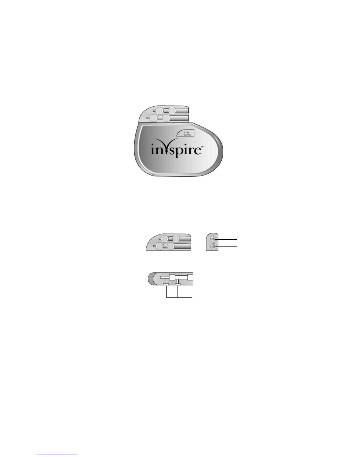
STIM port
SENSE port
Top view
Side view
Set screw locations
The implanted components of the Inspire system consist of an IPG, a respiratory sensing lead,
and a stimulation lead. All implanted Inspire system components are intended for single-use
only.
IPG
The IPG (Figure 2) contains the battery and electronics that deliver Inspire therapy and store
the therapy settings.
Figure 2. IPG
The IPG has two 3.2 mm low-profile connector ports (Figure 3), which are compatible with the
connectors on the stimulation lead and the respiratory sensing lead. After inserting the lead
connectors into the IPG connector ports, the lead connectors are secured using the set screws
next to the connector ports.
Figure 3. IPG connector ports
Inspire System Models 3024, 4063, 4323 English 9
Page 10
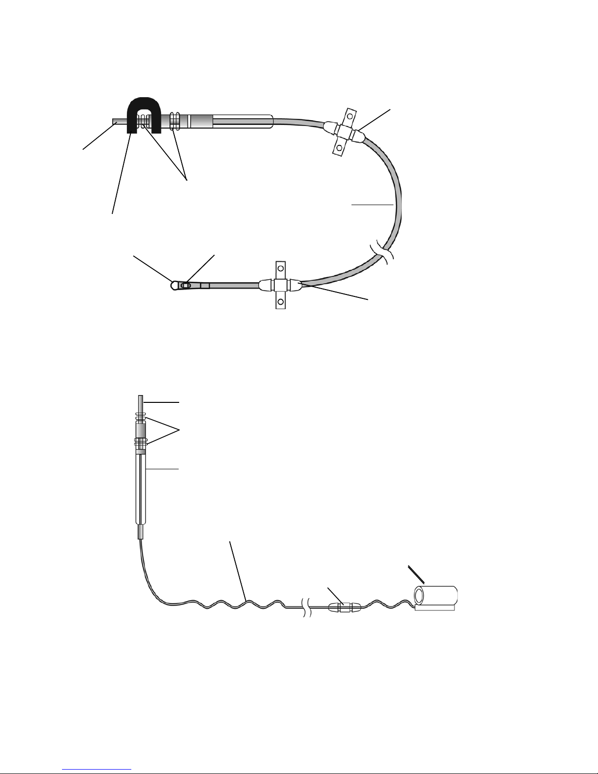
Leads
Shorting bar
Connector pin
Sealing rings
Lead body
Anchor: movable
Sensor tip
Anchor: fixed
Sensor membrane
Sealing rings
Self-sizing cuff
Connector
Anchor
Sigmoid lead body
Connector pin
The respiratory sensing lead (Figure 4) detects respiratory effort. The lead has a pressuresensitive membrane that converts the mechanical energy of respiration into an electrical signal.
Figure 4. Respiratory sensing lead
The stimulation lead (Figure 5) delivers stimulation to the hypoglossal nerve. The lead has a
flexible, self-sizing stimulation cuff. The stimulating electrodes are on the inner surface of the
cuff.
Figure 5. Stimulation lead
10 English Inspire System Models 3024, 4063, 4323
Page 11

Contraindications
Contraindications for the use of Inspire UAS therapy include the following:
• Central + mixed apneas > 25% of the total apnea–hypopnea index (AHI)
• Any anatomical finding that would compromise the performance of upper airway
stimulation, such as the presence of complete concentric collapse of the soft palate
• Any condition or procedure that has compromised neurological control of the upper airway
• Patients who are unable or do not have the necessary assistance to operate the sleep
remote
• Patients who are pregnant or plan to become pregnant
• Patients who will require magnetic resonance imaging (MRI)
• Patients with an implantable device that may be susceptible to unintended interaction with
the Inspire system. Consult the device manufacturer to assess the possibility of interaction.
Adverse Effects
Possible adverse effects include, but are not limited to, the following patient related conditions:
• Damage to blood vessels in the vicinity of implant
• Excessive bleeding
• Nerve trauma or damage
• Allergic and/or rejection response to the implanted materials
• Infection
• Local irritation, seroma, hematoma, erosion, or swelling
• Persistent pain, numbness, or inflammation at the implant site
• Discomfort from the stimulation
• Tongue movement restrictions, irritation resulting from tongue abrasions on preexisting
sharp or broken teeth
• Tongue soreness or weakness
• Problems with swallowing or speaking
• Undesirable change in stimulation over time, possibly related to tissue changes around the
electrode(s), shifts in electrode position, loose electrical connections, or lead fractures
• Fibrosis to the extent that it makes it difficult to remove the system without damaging
surrounding structures
•Dry mouth
• Other acute symptoms (i.e., headaches, coughing, choking, dysphasia, and speech
related events)
• Insomnia
Inspire System Models 3024, 4063, 4323 English 11
Page 12

Warnings and Precautions
Warnings
•Training — Physicians must be trained in the proper use and surgical procedure before
implantation or operation of the device.
• Pediatrics — The majority of cases of obstructive sleep apnea in younger pediatric
patients (e.g., less than 18 years of age) result from anatomical obstruction (e.g.,
adenotonsillar hypertrophy) that would not be appropriately managed with
neurostimulation therapy.
• Components — The use of components not provided by Inspire Medical Systems may
result in damaged components, improper operation, or increased risks to the patient.
• Diathermy — Do not use shortwave diathermy, microwave diathermy or therapeutic
ultrasound diathermy (all now referred to as diathermy) on patients implanted with a
neurostimulation system. Energy from diathermy can be transferred through the implanted
system and can cause tissue damage at the location of the implanted electrodes, resulting
in severe injury or death.
Diathermy can also damage the neurostimulation system components, resulting in loss of
therapy and requiring additional surgery for system explantation and replacement. Advise
your patient to inform all their health care professionals that they should not be exposed
to diathermy treatment.
Injury to the patient or damage to the device can occur during diathermy treatment when:
• The neurostimulation system is turned on or off
• Diathermy is used anywhere on the body—not just at the location of the
neurostimulation system
• Diathermy delivers heat or no heat
• Any component of the neurostimulation system (lead, extension, neurostimulator)
remains in the body
• Magnetic Resonance Imaging — The use of magnetic resonance imaging (MRI) among
IPG patients has been contraindicated by MRI manufacturers. Patients who have any
component of the Inspire system implanted should not undergo MRI. MRI can cause
tissue damage as well as damage to the Inspire system and components.
• Sleep remote use — When operating their Inspire sleep remote, patients should use
special care near flammable or explosive atmospheres. An interaction between the
flammable or explosive atmospheres and the battery in the sleep remote could occur. The
consequences of using the battery-powered sleep remote near flammable or explosive
atmospheres are unknown.
• Body Mass Index (BMI) — BMI greater than 32 was not studied as part of the pivotal trial.
Based on data from the feasibility study, it may be associated with decreased likelihood of
response to treatment. Use of Inspire UAS in higher BMI patients is not recommended due
to unknown effectiveness and safety.
12 English Inspire System Models 3024, 4063, 4323
Page 13

Precautions
General
• Pediatrics — The safety of implantation and the parameters for safe and effective
stimulation of the hypoglossal nerve have not been evaluated in clinical studies for patients
less than 22 years of age. There may be increased risk of nerve injury and stimulationrelated adverse events in this population, particularly in younger children (e.g., less than
12 years of age).
• Expiration date — Do not use any Inspire system product after its expiration date.
• Component handling — Precautions related to component handling during the implant
procedure are located on page 18.
• Storage temperature ranges
– Do not expose the IPG to temperatures above 52°C (125°F) or below -18°C (0°F).
– Do not expose the leads to temperatures above 55°C (131°F) or below -10°C (14°F).
Electromagnetic compatibility and medical procedures
For information on MRI and diathermy, see “Warnings” on page 12.
The IPG is designed to ensure immunity from most common sources of electromagnetic
disturbance. In most cases, turning off the electromagnetic disturbance source, or moving away
from the electromagnetic disturbance source will return the IPG to normal operation. Extremely
strong sources of electromagnetic disturbance could interfere with normal IPG operation,
causing the IPG to reset and requiring the IPG to be reconfigured. To reduce the possibility of
electromagnetic interference (EMI), patients are recommended to use therapy only while
asleep.
Medical environment
Electrocautery, irradiation, lithotripsy, RF-ablation, X-ray, and fluoroscopy are typical
electromagnetic disturbance sources in hospital and clinical environments. Medical treatments
that use ultrasonics, defibrillation, or radiation can adversely affect the Inspire system.
• Electrocautery — Electrocautery may induce failure of the IPG. Alternatives to
electrocautery should be used when available. Bipolar electrocautery should be used if
alternatives are not available. If electrocautery must be used in the vicinity of the IPG,
therapy should be turned off.
• Radiation therapy — The IPG should not be directly irradiated by therapeutic levels of
ionizing radiation (such as produced by cobalt machines or linear accelerators used for
cancer treatment) because of the risk of permanent damage to the IPG circuitry. If such
therapy is required in the vicinity of the IPG, shield the device and confirm its function after
treatment.
• RF-ablation — RF-ablation should not be used directly over the implant sites.
• X-ray and fluoroscopy — Exposure to diagnostic X-ray or fluoroscopic radiation should
not affect the IPG or leads.
• Therapeutic ultrasound — Exposure to high ultrasonic frequencies may result in damage
to the IPG or leads. It is not recommended to use high-output ultrasonic devices, such as
an electrohydraulic lithotriptor or bone growth stimulator on patients with an implanted IPG.
Inspire System Models 3024, 4063, 4323 English 13
Page 14

• Ultrasonic scanning — While there is no danger to the patient, ultrasonic scanning
equipment could cause mechanical damage to an IPG or leads if used directly over the
implant sites.
• Defibrillation — Defibrillation used anywhere on the patient’s body can cause permanent
damage to the IPG. Following defibrillation, the IPG should be interrogated to verify normal
operation.
Home or work environment
Based on laboratory tests of the IPG, the device should not be affected by the normal operation
of electrical equipment, household appliances, electric machine shop tools, microwave ovens,
internal combustion engines, low-powered radio, and microwave frequency transmitters. All
such equipment should be kept in good repair and properly grounded to avoid the possibility of
electrical shock or interference with the proper operation of the IPG.
Inspire therapy is intended for use during sleep only and should be turned off otherwise.
• Equipment operation — Patients should not operate potentially dangerous equipment,
such as power tools, during stimulation.
• Theft detectors — In general, theft detectors have been known to cause inadvertent and
potentially uncomfortable stimulation in neurological stimulation systems. Patients should
use care to avoid theft detectors and be aware in the presence of such systems.
• High-powered electric fields — Consult Inspire Medical Systems when the patient will
be in an area where contact with current carrying conductors is possible or near
high-powered electromagnetic fields radiated by arc welding units, induction furnaces,
induction stoves, resistance welders, radio or microwave frequency transmitters, etc.
• Mobile and cellular phones — Maintain a separation of at least 15 cm (6 in) between a
phone and the IPG.
14 English Inspire System Models 3024, 4063, 4323
Page 15

Storage and Handling
Recommendations for storage and handling of the IPG and leads are provided in this section.
Inspire Medical Systems sterilizes the IPG and leads with ethylene oxide (EtO) prior to
shipment.
Information about precautions for handling components is located on page 18.
IPG
Inspect the IPG and the lead sterile packages prior to opening. If the IPG package is damaged,
the IPG may be damaged as well. Return a damaged package to Inspire Medical Systems; see
the back cover of this manual for addresses.
Table 1. IPG Storage and Handling
Handling and Storage: Acceptable Unacceptable
Store and transport IPG within the
following environmental temperature
limits: -18°C (0°F) to +52°C (125°F).
A full or partial electrical reset condition
may occur at temperatures below
-18°C (0°F).
Resterilization
Resterilization is not allowed.
• IPGs cannot be resterilized. If the
sterile package seal is broken, or if
the packages are otherwise
damaged, do not use.
• Return the package to your local
Inspire Medical Systems
representative, see back cover for
address.
Do not implant the IPG if it has been dropped on
a hard surface from a height of 30 cm
(12 in) or greater.
Inspire System Models 3024, 4063, 4323 English 15
Page 16

Leads
If the lead sterile package seal is broken or the package is otherwise damaged, return the
package to Inspire Medical Systems. Leads cannot be resterilized.
Table 2. Lead Storage, Handling, and Resterilization
Handling and Storage: Acceptable Unacceptable
Store and transport leads within the
following environmental temperature
limits: -10°C (14°F) to +55°C (131°F).
Only use sterile-gloved hands to handle
the lead; rinse sterile surgical gloves in
sterile water before handling the lead.
Protect leads from materials that shed
lint and dust.
Exercise care and appropriate
instrument selection when handling the
stimulation lead cuff with a surgical
instrument.
Resterilization
Leads cannot be resterilized.
• If the sterile package seal is broken,
or if the packages are otherwise
damaged, do not use.
• Return the package to Inspire
Medical Systems; see the back
cover of this manual for addresses.
Do not implant a lead that was dropped.
Avoid excessive traction or sharp instruments.
Avoid severe bending, kinking, stretching, or
handling with surgical instruments.
Do not immerse a lead in mineral oil or silicone
oil.
Do not expose the respiratory sensing lead to
static electricity.
16 English Inspire System Models 3024, 4063, 4323
Page 17

Physician Training
STIM
SENSE
Prior to implanting an Inspire system, surgeons will receive classroom instruction on Inspire
implant techniques as well as cadaver training. Sleep physicians and sleep technicians will
receive classroom instruction on how to titrate the device including hands on operation of the
programmer.
System Implant
This section describes a general implant procedure for the Inspire system.
Implantable Components
The Inspire system includes the following implantable components:
• Inspire II implantable pulse generator (Model 3024)
• Inspire respiratory sensing lead (Model 4323)
• Inspire stimulation lead (Model 4063)
The IPG has two lead connector ports (Figure 6). The connector port for the respiratory sensing
lead is marked SENSE. The connector port for the stimulation lead is marked STIM.
Figure 6. IPG and connector ports
Inspire System Models 3024, 4063, 4323 English 17
Page 18

Procedure Overview
The implant procedure begins with preoperative planning. It is recommended that the
stimulation lead be the first Inspire component to be implanted. Secondly, a subcutaneous
pocket is created for the IPG. The connector end of the leads will be tunneled to this pocket.
After the stimulation lead is implanted, the respiratory sensing lead is implanted. After tunneling
the connector end of the leads to the IPG pocket, the leads are connected to the IPG and the
IPG is secured in the subcutaneous pocket.
Patient Preparation
• Ensure the tongue is visible during the surgical procedure in order to observe the response
to intraoperative test stimulation.
• The recommended body side for system implantation is the right side.
• Extend the patient’s right arm away from his or her side to allow access to the thorax for
respiratory sensor implantation.
• The patient's head and neck should be positioned to provide optimal access to the
hypoglossal nerve.
– Antimicrobial incise drape may be used.
– Use only short acting paralytic agent to preserve tongue response.
• A nerve monitoring system is recommended to locate the hypoglossal nerve and confirm
nerve recruitment.
• Surgical incisions are recommended to be made on natural skin creases to minimize
visible scarring.
• The patient should be given antibiotics preoperatively as well as postoperatively.
Surgical Materials
An Inspire system implant requires typical surgical equipment used during neck surgeries. The
following is a list of additional materials typically used during the system implant procedure:
• Sterile sleeve, bag or equivalent (to bring the telemetry cable into the sterile field)
• Right angled forceps or hemostat (for cuff electrode placement)
• A nerve monitoring and stimulation system (to locate the hypoglossal nerve and confirm
nerve recruitment)
Precautions for Handling Components
• The implanted components of this system should be carefully handled to avoid damage by
excessive traction or sharp instruments. Any component showing signs of damage should
not be used.
Caution: No instrument of any type should touch the sensor membrane. The
sensor membrane covers the sensor, the flat square recessed surface near the
tip of the respiratory sensing lead. Touching the sensor membrane will result in
damage to the sensor.
18 English Inspire System Models 3024, 4063, 4323
Page 19

Figure 7. Sensor membrane
Sensor membrane
– IPG drop — If the IPG is dropped more than 30 cm (12 in) onto a hard surface, it should
not be used.
– Setscrew cautions — Counterclockwise rotation of a set screw beyond one or two
revolutions while retracting it from the connector port may disengage the setscrew from
the connector block. Do not use any hex wrench other than the one packaged with the
IPG.
– Leads should be handled with great care at all times. Any severe bending, kinking,
stretching, or handling with surgical instruments may cause permanent damage to the
lead body or the cuff. Do not implant a lead that was dropped.
– Lead insulators attract small particles, such as lint and dust; therefore, to minimize
contamination, protect the lead from materials shedding these substances. Handle the
lead with sterile surgical gloves that have been rinsed in sterile water.
– Do not immerse leads in mineral oil or silicone oil.
• Static electricity — The respiratory sensing lead is sensitive to static electricity.
Therefore, the shorting bar should be left in place and removed just prior to implant.
Cautions:
• The black, U-shaped shorting bar must not be removed except during
tunneling and immediately prior to connecting the lead to the IPG.
• After tunneling, if the lead is not immediately connected to the IPG, the black,
U-shaped shorting bar must be reattached.
Inspire System Models 3024, 4063, 4323 English 19
Page 20

Stimulation Lead Implant
Long outer
flap
Short inner
flap
Electrodes
The stimulation lead is designed with a cuff that is placed around the hypoglossal nerve after
the nerve is exposed.
The following is an overview of the recommended process for implanting the stimulation lead:
• Expose the hypoglossal nerve (see “Exposing the hypoglossal nerve” below).
• Place the cuff around the nerve and irrigate the cuff and nerve with sterile saline.
• Test the electrode placement using the IPG or an external nerve stimulator.
• Secure the stimulation lead anchor to the digastric muscle with permanent sutures.
• Form the IPG pocket and tunnel the lead connector to the pocket.
Exposing the hypoglossal nerve
1. Make a 4–6 cm (1.6–2.5 in) incision along a natural skin crease from
3–4 cm (1.2–1.6 in) below the right edge of mandible.
2. Retract the submandibular gland cephalad.
3. Identify the digastric muscle, and carefully dissect in the submandibular triangle to identify
the hypoglossal nerve.
4. Once the nerve is identified, it may be stimulated at a low setting (for example 0.5 mA)
using an external nerve stimulator to confirm nerve function. Do not over stimulate the
nerve with the external device.
5. Expose 1–2 cm (0.4–0.8 in) length of the hypoglossal nerve.
Cautions:
• Do not apply tension to the nerve and supporting tissue while exposing the
nerve and placing the cuff.
• Preserve the small nutrient blood vessels along the nerve fibers.
• Maintain hemostasis. Fluid residuals increase the chances of hematoma
formation and infection.
Placing the stimulation lead
To place the stimulation lead cuff, the cuff’s short inner and long outer flaps (Figure 8) are
wrapped around the hypoglossal nerve.
Figure 8. Stimulation lead cuff flaps
20 English Inspire System Models 3024, 4063, 4323
Page 21

Refer to Figure 9 while completing cuff placement steps 1 through 4.
1. Using a right-angled forceps positioned under the nerve, grab the long outer flap.
Caution: Do not force the cuff into position. Be sure that a sufficient opening has
been cleared. Forcing the cuff into position may result in nerve damage.
2. Hold the short inner flap open.
3. Pull the short inner flap over the nerve, then lay the long outer flap over the inner flap.
Cautions:
• Be sure that the cuff flaps are properly placed.
• Do not suture the cuff around the nerve. The cuff is designed to expand and
contract with the nerve. Suturing the cuff in place may result in nerve damage.
4. Make sure both flaps encircle the nerve.
5. Irrigate the cuff and nerve with sterile saline to facilitate adequate electrical contact
between the electrodes and the nerve.
Figure 9. Placing the cuff around the hypoglossal nerve
Inspire System Models 3024, 4063, 4323 English 21
Page 22

Test Stimulation
Use intraoperative test stimulation to help confirm proper lead position. Steps 1–6 describe test
stimulation with the IPG; step 7 describes an alternative method using a stimulator other than
the IPG.
1. Confirm that IPG therapy is off.
2. Insert the stimulation lead connector into the IPG connector port marked STIM (Figure 10).
Note: Refer to page 31 for instructions on connecting the stimulation lead to the IPG.
Figure 10. Insert the stimulation lead into the connector port marked STIM
3. Program the IPG using the physician programmer (see the programming manual for
instructions). It is recommended to start at 0.5 volts and increase stimulation in 0.2 volt
increments. Conduct intraoperative test stimulation while observing the tongue and neck
area for signs of patient muscle response to stimulation.
4. Verify that the stimulation gives the appropriate response. Reposition the lead as
necessary. During and after repositioning of the lead, apply sterile saline to the cuff to
facilitate electrical contact of the cuff electrodes with the nerve. Continue to reposition the
cuff if a stimulation response does not occur.
5. Confirm that IPG therapy is off when finished with intraoperative test stimulation.
6. Carefully disconnect the stimulation lead connector from the IPG.
Cautions:
• Use care not to dislodge the lead.
• Use care to not loosen the IPG set screws too far, which can result in the set
screws unseating from the connector.
7. Alternate method:
a. Use an approved external stimulator to conduct intraoperative test stimulation as an
alternative to using the IPG.
b. The external stimulator will require sterile wires to interface with the connector of the
stimulation lead.
c. Repeat the stimulation process described in steps 3 and 4 above to ensure proper
placement of the cuff.
22 English Inspire System Models 3024, 4063, 4323
Page 23

Securing the Stimulation Lead
The stimulation lead is anchored to the tissues surrounding the hypoglossal nerve. The
suggested method for anchoring the lead body is to anchor it to the digastric muscle using
permanent sutures (Figure 11).
1. Position the cuff and stimulation lead:
• Maintain the cuff and stimulation lead body parallel to the nerve to avoid placing torque
or tension on the nerve.
• It is recommended that the spine of the cuff is positioned inferior to the nerve.
2. Secure the stimulation lead with adequate strain relief by creating a lead loop in between
the stimulation lead cuff and the anchoring site (e.g., digastric muscle).
3. Using both anchor recesses, tie permanent sutures to the anchor, then secure the anchor
to the digastric muscle using the sutures.
4. It is recommended that the physician not close the neck incision until all system
components are implanted and tested. Consider gently packing the neck incision with 4x4
gauze soaked in a saline/antibiotic solution. Remove such packing with care prior to
closing the incision so as not to dislodge or disrupt the cuff placement.
Cautions:
• Make sure that the anchor points are located in tissue that moves with the
hypoglossal nerve.
• Do not loop the lead such that the lead body crosses and touches itself.
Crossing the lead bodies can result in fibrosis at the intersection point and
reduce strain relief in the lead body.
• Place sutures only around the anchor region of the lead.
• Surgical instruments should not be used to handle the lead body directly. The
lead is easily kinked and the insulation is easily damaged. Care should be
used when handling the lead. Surgical instruments may be used for handling
the lead anchor.
Inspire System Models 3024, 4063, 4323 English 23
Page 24

Cuff
Strain relief loop
Lead anchor (attached to digastric muscle)
Hypoglossal nerve
Digastric muscle
Lead passes under digastric
muscle and does not touch
itself when crossing
Figure 11. Anchoring the stimulation lead
24 English Inspire System Models 3024, 4063, 4323
Page 25

Making the IPG Pocket
Collet
Tip
When selecting the location for the IPG pocket, consider patient lifestyle factors, such as the
use of firearms, carrying backpacks, and other work or recreation related activities. The
following instructions reflect the typical IPG pocket location.
1. Make a 5–6 cm (1.9–2.4 in) incision mid-line 2–3 cm (0.8–1.2 in) below the right clavicle,
taking precautions to ensure that the patient’s typical arm movements with activities of
daily living will not cause the IPG to ride up onto the clavicle.
2. Make a subcutaneous pocket of sufficient size to contain the IPG and any excess lead
wrap, which can typically be expected.
Tunneling the Lead
These instructions apply to both the stimulation lead and the respiratory sensing lead. Use the
tunneling tool to pass the lead connector from the point of lead implantation to the
subcutaneous pocket, avoiding sharp angle bends of the lead body. An intermediate incision
between the lead implant site and the IPG subcutaneous pocket is usually not necessary.
1. Locate the sterile tunneling tool (Figure 12) provided with the stimulation lead packaging.
• Prior to assembly, the rod may be bent into a bow shape to aide tunneling. Generally, it
is better to make multiple gentle bends than a single sharp bend.
• The tool is assembled by threading the tip and the collet assembly to the stainless steel
rod. Attach the tip first and the collet only after the tunnel is established.
Figure 12. Tunneling tool components
2. Simulate the final positioning by identifying where the lead connector will exit the eventual
tunnel.
3. Tunnel the tunneling tool from the lead incision to the IPG pocket before attaching the
collet. Advance the tunneling tool subcutaneously until the tip is exposed in the IPG
pocket.
Cautions:
• Follow the tunneling path established in step 2. Deep tunneling is not
desirable. Pass the lead superficially to avoid damage to deep structures.
• To avoid damage to the lead or body tissue, do not use excessive force or
surgical instruments when using the tunneling tool.
• For the stimulation lead, tunneling the lead under the clavicle bone is not
recommended. A lead tunneled under the clavicle bone creates an
increased risk of damage to veins and/or arteries.
• To avoid damage to the collet, do not attach it to the tunneling tool until the
tunnel is established from the lead implant site to the IPG pocket.
Inspire System Models 3024, 4063, 4323 English 25
Page 26
Caution: For the respiratory sensing lead, to avoid electrical damage to the
A
B
sensor, avoid using cautery during the tunneling procedure and prior to
connecting the lead to the IPG. The black, U-shaped shorting bar must be
attached to the lead if cautery is performed and the lead is not connected to
the IPG.
4. For the respiratory sensing lead, remove the shorting bar from the connector; for the
stimulation lead, proceed to step 5.
Caution: Avoid touching the lead connector within 2 cm (0.8 in) from the end
after the shorting bar is removed and until the lead is connected to the IPG.
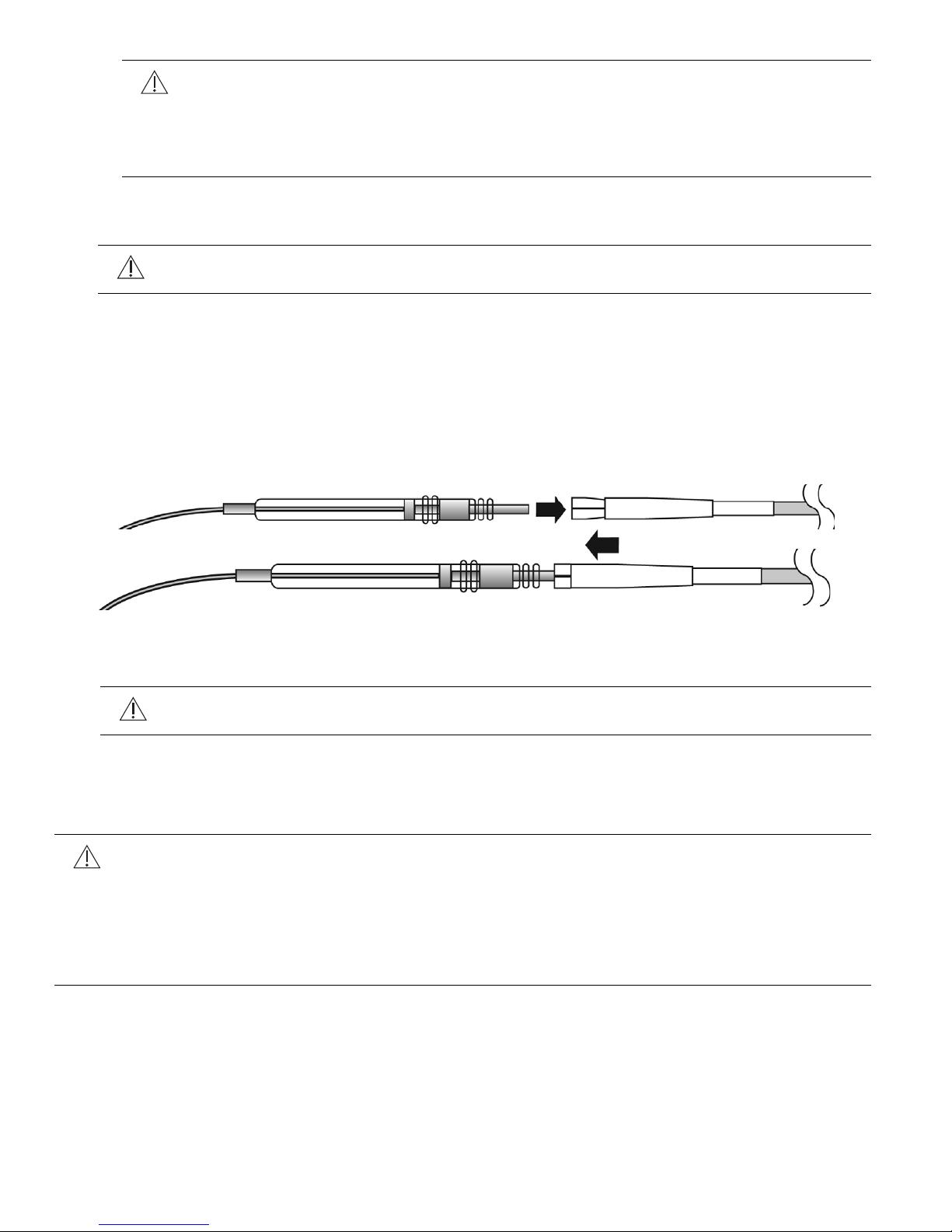
5. Insert the lead connector into the tunneling tool collet as follows:
a. Slide the collet sleeve down toward the tunneling tool tip to allow the lead connector to
be inserted into the collet.
b. Insert the pin of the lead connector into the collet of the tunneling tool (Figure 13 A)
c. Slide the sleeve over the collet to lock the connector pin in place (Figure 13 B).
d. It is not necessary to exert excessive force to secure the sleeve over the collet.
Figure 13. Inserting lead connector into tunneling tool collet
6. Gently pull the lead out through the exit site in the IPG pocket.
Caution: Be sure the lead is routed so as to avoid sharp bends or kinks in the
lead body.
7. Remove the lead from the tunneling tool by sliding back the sleeve from the collet.
Respiratory Sensing Lead Implant
Cautions:
• Use care when handling the lead. The pressure sensor is susceptible to damage
due to electrostatic discharge. Leave the black U-shaped clip on the connector in
place except during tunneling and connection to the IPG.
• Do not touch the recessed sensing membrane of the sensor with surgical tools as
this will damage the sensor.
26 English Inspire System Models 3024, 4063, 4323
Page 27
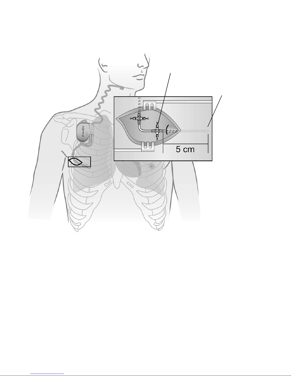
The respiratory sensing lead is placed in the extrapleural space (Figure 14).
Sensor
Sensor membrane
must face pleura
Anchor with
raised ridges
The potential complications of bleeding and tension pneumothorax can be avoided by
positioning the incision as outlined in the following steps:
Figure 14. Respiratory sensing lead extrapleural placement
1. Make a 4–6 cm (1.6–2.4 in) incision starting near the midaxillary line, parallel to the ribs,
and toward midline on the right side of the chest.
Note: The respiratory sensing lead will be tunneled approximately 3–5 cm (1–2 in) in
length between the intercostal muscle layers, and therefore the incision should be
approximately 3–5 cm (1–2 in) from the desired sensor location. The desired sensor
location is in line with the nipple.
Note: A neurovascular bundle is located inferior to each rib. Therefore, implantation of the
sensor should be as close as possible to the superior rib surface.
2. Place the sensor between ribs 2–6, with a preference for the 4th or 5th intercostal space.
3. Use sharp and blunt dissection to expose the intercostal muscle layers.
• Dissection is required to reach and identify the internal intercostal muscle.
• The sensor will be inserted between the internal intercostal muscle and the external
intercostal muscle layers.
Inspire System Models 3024, 4063, 4323 English 27
Page 28

4. Insert the tip of the respiratory sensing lead between the internal and external intercostal
muscle layers at a shallow angle along the superior edge of the inferior rib forming the
intercostal space.
Note: Enter the intercostal space toward the medial side of the incision in order to provide
lateral space for lead anchoring within the incision.
5. Insert approximately 3–5 cm (1–2 in) of the length of the distal lead between the internal
and external intercostal muscle layers.
• The sensor membrane (flat surface) is required to face toward the pleura.
• Raised ridges on the distal anchor are to face up, which confirms that the sensor
membrane is facing toward the thoracic cavity.
6. Secure the respiratory sensing lead with permanent sutures using the two winglet features
and two grooves of each of the two anchors on the respiratory sensing lead (i.e., eight total
sutures to secure both anchors).
• Ensure that the sensor membrane orientation is maintained during suturing of the
anchors.
Note: The distal anchor is adhered to the lead body, and the second anchor may be slid
along the lead body to the desired position. If the second anchor does not slide, use saline
to moisten the lead body, which may improve the ability to slide the anchor. Position the
sliding anchor to direct the lead toward the IPG pocket. Leave a small amount of excess
lead length between the two sutures to allow the sutures to move with the body without
placing tension on the lead. The excess lead should form an omega shape between the
two lead anchors.
7. Suture the anchor in place to the subcutaneous tissues.
8. Check that the lead body exiting the intercostal muscles transitions smoothly before
tunneling to the IPG pocket, forming the recommended omega-shaped strain relief
between the two anchors.
#
Caution: Do not loop the lead such that the lead body crosses and touches
itself. Crossing the lead bodies can result in fibrosis at the intersection point and
reduce strain relief in the lead body.
9. Tunnel the connector end of the respiratory sensing lead to the IPG pocket using the
tunneling tool. Refer to “Tunneling the Lead” on page 25 for instructions.
28 English Inspire System Models 3024, 4063, 4323
Page 29
Connecting the Leads and IPG
Caution: Saline or bodily fluids in the IPG connector may reduce battery longevity.
• Do not allow saline or bodily fluids to enter the IPG connector ports.
• Confirm that lead connectors are dry prior to inserting them into the IPG ports.
• Use care when inserting the hex wrench to avoid damage to the seals.
• Confirm that setscrew seals fully close after securing the lead in place.
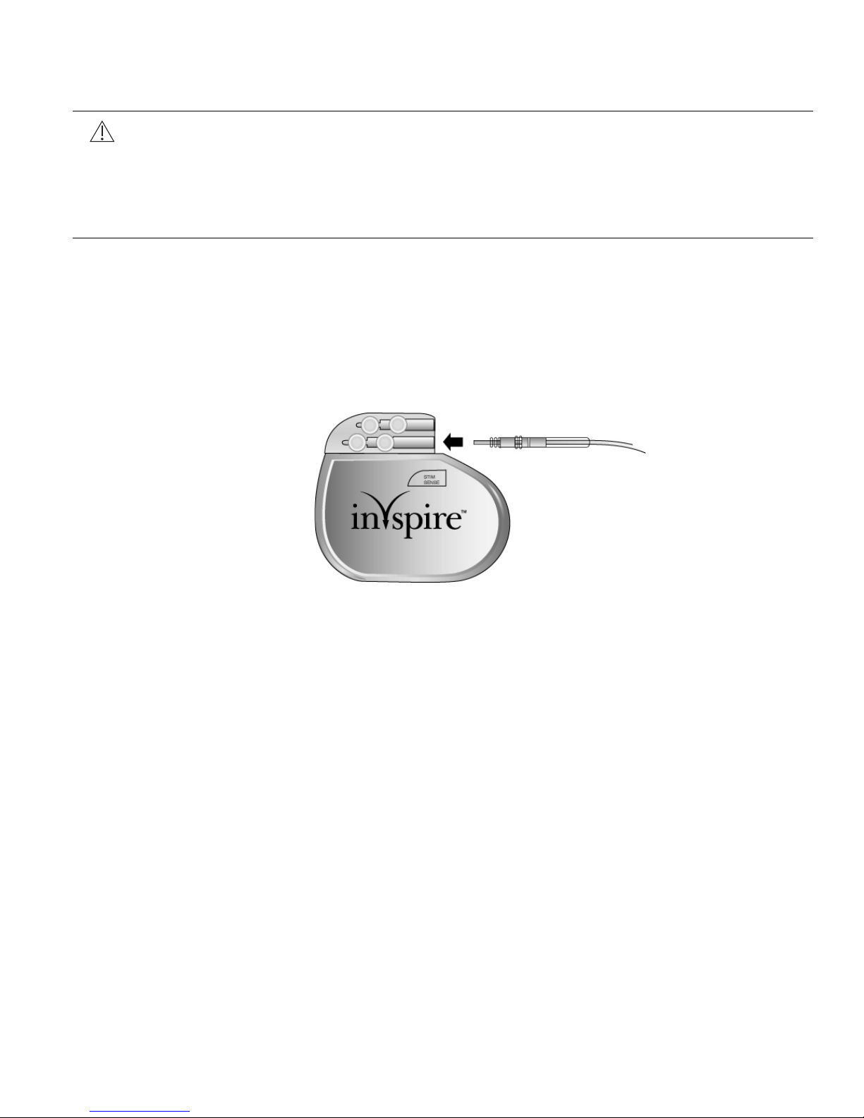
Connect the respiratory sensing lead to the IPG
1. Wipe off any body fluids from the respiratory sensing lead connector.
2. Grasping the lead approximately 3 cm (1.2 in) from the connector end, insert the lead
connector into the IPG connector port marked SENSE (Figure 15).
• Make sure the lead connector is fully inserted into the IPG connector port by verifying
that the lead connector pin reaches the back of the IPG connector port cavity.
Figure 15. Insert the respiratory sensing lead connector into IPG connector port marked
SENSE
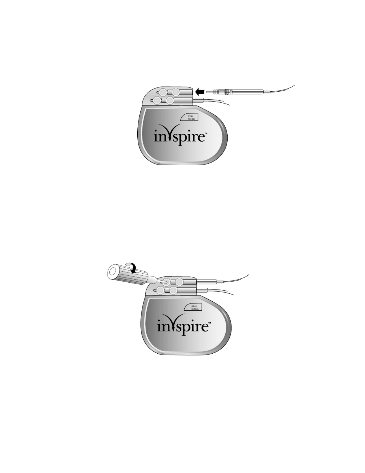
3. Use the white-handled hex wrench to tighten the 2 setscrews adjacent to the SENSE port
(Figure 16) until resistance is felt, then tighten each screw 1/4 turn more. Do not over
tighten.
• Tighten the setscrew furthest from the lead port first.
• Prior to tightening the setscrew nearest to the lead port, gently tug the lead to confirm
that the first setscrew has secured the lead in place.
• After tightening both setscrews, confirm that the seals covering the setscrews are fully
closed.
Inspire System Models 3024, 4063, 4323 English 29
Page 30

Figure 16. Tighten the two lower setscrews
4. Test the sensor function as follows:
a. Place the telemetry cable into a sterile sleeve and hold the telemetry head centered
over the IPG.
b. Verify sensor function by observing a sensor waveform on the using the programmer.
c. Once function has been verified, turn the therapy off.
30 English Inspire System Models 3024, 4063, 4323
Page 31
Connect the stimulation lead to the IPG
1. Wipe off any body fluids from the stimulation lead connector.
2. Grasping the lead approximately 3 cm (1.2 in) from the connector end, insert the lead
connector into the IPG connector port marked STIM (Figure 17).
• Make sure the lead connector is fully inserted into the IPG connector port by verifying
that the lead connector pin reaches the back of the connector port cavity.
Figure 17. Insert stimulation lead connector into IPG connector port
3. Use a white-handled hex wrench to tighten the 2 setscrews adjacent to the STIM port
(Figure 18) until resistance is felt, then tighten each screw 1/4 turn more. Do not over
tighten.
• Tighten the setscrew furthest from the lead port first.
• Prior to tightening the setscrew nearest to the lead port, gently tug the lead to confirm
that the first setscrew has secured the lead in place.
• After tightening both setscrews, confirm that the seals covering the setscrews are fully
closed.
Figure 18. Tighten the two upper setscrews
Inspire System Models 3024, 4063, 4323 English 31
Page 32

Implanting the IPG
When implanting the IPG, consider patient lifestyle factors, such as the use of firearms, carrying
backpacks, and other work or recreation related activities.
1. Wrap the excess lead body behind the IPG (Figure 19) and position the IPG and wrapped
excess lead body in the pocket. Implant the IPG with the logo facing up toward the skin.
Figure 19. Wrap excess lead length
Caution: When placing the IPG and leads into the subcutaneous pocket:
•Do not coil the leads. Coiling the leads (Figure 20) can twist the lead bodies
and may result in lead dislodgement.
•Do not grip the leads or IPG with surgical instruments.
• Ensure that the IPG logo is facing up toward the skin.
p
Figure 20. Do not coil excess lead length
2. Test the system using the physician programmer.
a. Place the telemetry cable into a sterile sleeve and hold the telemetry head centered
over the IPG.
b. To check stimulation function, evaluate both the stimulation response and the sensor
waveforms. Refer to the physician programming manual for instructions.
32 English Inspire System Models 3024, 4063, 4323
Page 33

3. Following the system function check, verify that the therapy is off and the stimulation
amplitude is programmed to 0 volts. It is recommended to keep the therapy off for the first
month after the implant surgery to allow for healing and encapsulation of the stimulation
lead.
Completing the Implant Procedure
After testing, complete the implant procedure:
1. Secure the IPG by placing permanent sutures through one of the two suture holes and
attaching to the fascia (not to muscle).
2. Irrigate all incision sites with a generous amount of bacitracin and saline solution or
equivalent before closing.
3. Close the surgical incisions.
4. At the discretion of the physician, antibiotics may also be administered postoperatively.
Postoperative Follow-up
Follow up with normal postoperative care. A 7–14 day check of surgical incision healing is
recommended.
To allow for healing after surgery, the system should not be activated for about 1 month following
implant. Refer to the Inspire programmer manual for additional information.
Regular patient follow-up should be scheduled to monitor the condition of the IPG battery and
to confirm that the therapy values are appropriate.
Inspire System Models 3024, 4063, 4323 English 33
Page 34

Physician Instructions to Patient
Give the patient information concerning the Inspire system. This should include information on
the IPG, the sleep remote, the stimulation lead, and the respiratory sensing lead.
Patients should be instructed as follows:
• It is normal to feel some discomfort from the incisions and to have some pain at the implant
sites for 2–6 weeks.
• It is best to avoid bending or twisting for several weeks after the implant procedure, as such
movements could impair the healing process. This time period allows the leads and IPG
to fix themselves more securely in place.
• Avoid physical activities that could damage the implant site or implanted device.
• Inform personal physicians, consulting physicians, or dentists that they have an implanted
stimulation system.
• Carry their Inspire Medical Systems ID card at all times.
The “Precautions” section on page 13, which includes information about cellular phones and
electromagnetic interference in the home or work environment, should also be conveyed to the
patient.
Patient Registration
Upon completion of the registration form by the clinician, this form serves as a permanent
record of facts related to the implanted device. A copy of this form should be returned to Inspire
Medical Systems. Refer to the back cover of this manual for mailing address.
Therapy Activation
Inspire therapy should be activated approximately 4 weeks after the implant procedure to allow
for healing.
Therapy Titration
At least one sleep study will be needed approximately 4–8 weeks after therapy activation to
titrate stimulation settings. Additional titration sleep studies may be needed to improve therapy
effectiveness and patient comfort.
34 English Inspire System Models 3024, 4063, 4323
Page 35

Surgical Revision and Explant
Lead Repositioning
• If the stimulation or respiratory sensing lead becomes displaced, any repositioning should
be attempted as soon as possible, before scar tissue builds up.
• If the lead must be repositioned (or removed) proceed with caution to avoid damage to
surrounding tissue.
• Extreme forces used during removal can damage leads or result in dismantling of the
leads.
• If removal is unavoidable, return the removed lead, or portion thereof, to Inspire Medical
Systems.
System or IPG Explant
• Extreme forces used during removal can damage the lead or result in dismantling of the
lead.
• A lead that has been cut off should have the remaining lead end sealed.
• If the leads are left in place, the proximal connector ends of the leads should be capped to
minimize tissue irritation and induced currents.
• Lead removal may not be possible due to the risk of damaging surrounding structures. The
decision to remove the leads or leave them in place is made between the physician and
the patient on a case by case basis. The implications of both options should be discussed,
for example:
– Removing the leads will extend the duration of the surgical procedure, require two
additional incisions, and require the dissection of fibrotic tissue that may have formed
around the leads.
– Leaving the leads in place means the patient will still be susceptible to electromagnetic
interference, which may prevent the patient from receiving an MRI. Furthermore,
patients must be made aware that they need to notify medical personnel that they still
have implanted leads even if the IPG has been removed and the lead ends have been
capped.
• Return all explanted components to Inspire Medical Systems for disposal.
Explant Disposition
When replacing an IPG, (due to battery depletion or explanting the IPG at the death of a patient
who is to be cremated) return the IPG to Inspire Medical Systems for analysis and disposal.
See the back cover of this manual for mailing address.
Inspire System Models 3024, 4063, 4323 English 35
Page 36

Clinical Summary
Stimulation Therapy for Apnea Reduction (STAR) Clinical Trial
The Inspire Upper Airway Stimulation (UAS) system was evaluated in a multicenter trial at study
centers in the United States and Europe for the indication of moderate to severe obstructive
sleep apnea (OSA) in patients who were not effectively treated by continuous positive airway
pressure (CPAP).
Patients Studied
The study enrolled 929 OSA patients. These patients were evaluated against patient selection
criteria that included moderate to severe OSA, a BMI (body mass index) less than or equal to
32, and the absence of a complete concentric collapse at the level of the soft palate. Following
the evaluation period, 126 patients met all selection criteria and proceeded to implant. All 126
implant procedures were successful, and 124 of the 126 implanted patients provided evaluable
data through at least 12 months. The STAR trial was an intent to treat study. Therefore, the 2
patients who did not provide evaluable data through 12 and 18 months post-implant are
assumed to be non-responders and were included in the evaluation as such. The patient
demographics for the STAR trial are included in Table 3. The patients' baseline AHI showed a
mean of 32.0 and a median of 29.3, and the baseline ODI showed a mean of 28.9 and a median
of 25.4.
Table 3. STAR Trial Subject Demographics
Continuous Measures Mean
N = 126
Age, year 54.5 55
Body Mass Index, kg/m2 28.4 29.2
Neck Size, cm 41.2 41.9
Systolic BP, mmHg 128.7 128
Diastolic BP, mmHg 81.5 80.5
Male 105 (83%) Total N = 126
Race
Caucasian
African American
Hispanic
Asian
Others*
122 (97%)
0 (0%)
1 (1%)
1 (1%)
2 (2%) * 1-Surinam, 1-Turkey
Median
36 English Inspire System Models 3024, 4063, 4323
Page 37

Study Design and Methods
The STAR trial was a multicenter, prospective trial with a 12-month single arm study and a
randomized controlled therapy withdrawal study at 13 months. Following implant of the Inspire
system, patients were followed at 1, 2, 3, 6, 9, 12, 13, 15, 18 months, and every 6 months
thereafter. The patients' baseline AHI and ODI (oxygen desaturation index) values were the
mean results from their screening (pre-implant) and 1-month (post-implant but prior to therapy
activation) sleep studies. Baseline results were compared to the 12-month results to determine
the percentage of patients who experienced a clinically meaningful reduction in the severity of
their OSA in terms of their AHI and ODI scores. For this study, a clinically meaningful reduction
in AHI and ODI was defined as (1) a 50% reduction in the AHI compared to the pre-implant
screening and 1-month visit (post-implant but prior to therapy activation) and an AHI < 20 events
per hour, and (2) a 25% or greater reduction in ODI at the 12-month visit compared to baseline.
Upon completion of the overnight sleep study at the 12-month visit, a randomized controlled
therapy withdrawal study was conducted. The first 46 responders were randomized 1:1 to either
the therapy maintenance (ON) group or the therapy withdrawal (OFF) group, resulting in 23
subjects in each group. Patients randomized to the therapy withdrawal group had Inspire
therapy turned OFF for at least five days. Patients randomized to the therapy maintenance
group continued their use of the Inspire system. All randomized patients participated in a sleep
study at the 13-month visit. The therapy withdrawal group had the sleep study performed with
Inspire therapy OFF, and the therapy maintenance group had the sleep study performed with
the Inspire therapy ON. The mean change of AHI for each arm was compared to determine the
extent of treatment effect from Inspire therapy.
The percentage of sleep time a patient had an oxygen saturation (SaO
) level below 90% was
2
recorded during the sleep studies, and two validated quality of life questionnaires were
administered at follow-ups through 18 months. The quality of life questionnaire was the Epworth
Sleepiness Scale (ESS), which rates a patient's daytime sleepiness, and the Functional
Outcomes of Sleep Questionnaire (FOSQ), which assesses the effect of a patient's daytime
sleepiness on activities of ordinary living. The hypotheses for the secondary efficacy endpoints,
which included the randomized withdrawal study, FOSQ, ESS, and SaO2, were tested
according to a hierarchical strategy in order to preserve an overall Type I error rate of 5%.
Inspire System Models 3024, 4063, 4323 English 37
Page 38

Study Results
Titration
All subjects underwent polysomnography (PSG) for titration of therapy settings at 2 and 6
months. Additional titration PSG studies were performed as needed. Through 18 months,
patients had an average of 3.3 (range 2–6) titration studies.
Safety
Of the 126 patients implanted with the Inspire UAS system in the STAR trial, 124 were followed
through 18 months. There were no unanticipated events and only 2 events required surgical
intervention. Both events consisted of an IPG migrating out of position and were resolved with
a surgical procedure performed under local anesthesia to reposition the IPG.
Many of the procedure-related adverse events reported are expected with a surgical procedure.
The procedure-related events are described in Table 4.
Table 4. Procedure-Related Adverse Events
(and the probability of experiencing them in the first 18 months)
Event Number of Subjects
with Event
Percent of Subjects
(n=126)
Incision pain 35 28%
Post-operative discomfort 31 25%
Temporary tongue weakness 23 18%
Sore throat from intubation during
15 12%
implant
Other post-operative symptoms
14 11%
(such as gastrointestinal (nausea,
vomiting, abdominal pain,
constipation), body pain (back,
knee, wrist, hand), allergy to
antibiotics, anxiety, ineffective
airway clearance, loss of some
taste, inability to void)
Headache 8 6%
Mild infection 1 1%
38 English Inspire System Models 3024, 4063, 4323
Page 39

The device-related adverse events are described in Table 5.
Table 5. Device-Related Adverse Events
(and the probability of experiencing them in the first 18 months)
Event Number of Subjects
Discomfort due to electrical
with Event
59 47%
Percent of Subjects
(n=126)
stimulation
Tongue abrasion 30 24%
Other acute symptoms (i.e.,
23 17%
headaches, coughing, choking,
dysphasia, and speech-related
events)
Mouth dryness 14 11%
Complaints related to temporary
13 11%
usability or functionality issues
with an implanted device
Complaints related to temporary
13 10%
usability or functionality issues
with an external device
Mechanical pain associated with
10 8%
presence of device
Mild infection 1 1%
At the completion of the 18-month follow-up visits of all study patients, 75% of device-related
events were fully resolved, primarily with either medication, device reprogramming, dental work
to fix a jagged tooth, or with the aid of a lower tooth guard used during sleep to prevent tongue
abrasions, or no intervention. Twenty-five percent (25%) of device-related events were
unresolved at 18 months. Currently unresolved events include reports of discomfort due to
stimulation, tongue abrasion and various stimulation related events including dry mouth,
headaches, intermittent waking, isolated stimulation sensation events, audible buzzing, and
intermittent fatigue. Despite these reported events, patients continued to report high (85%)
compliance with the therapy at 18 months.
Two subjects had their devices removed, which required a surgical procedure. One chose to
have the stimulator removed, and the leads were capped and left in the patient. The other had
the entire system removed as a precaution due to proximity to an infection. Both explants were
successfully completed without damage to the surrounding structures. There were 3 deaths
over the course of the study, all of which were unrelated to Inspire therapy. There were 32
serious adverse events (SAE), 2 of which were related to Inspire therapy.
Inspire System Models 3024, 4063, 4323 English 39
Page 40

Efficacy
The sleep studies, which were scored by an independent sleep scoring core lab, showed
statistically significant and clinically relevant reductions in the patients' AHI and ODI scores.
Table 6 reports the percentage of patients who experienced a clinically meaningful reduction in
their OSA severity (i.e., responders). As this is an intent to treat study, these results are based
on a total of 126 patients even though only 124 patients provided evaluable data through 12 and
18 months. The other 2 patients are assumed to be non-responders and are included in the
evaluation as such.
Table 6. Therapy Responders at 12 Months Post-Implant
Responder Responder Rate at
50% Reduction in AHI from
12-Month Follow-Up
66% (83/126) 65% (80/124)
Responder Rate at
18-Month Follow-Up
baseline and AHI < 20
25% Reduction in ODI from
75% (94/126) 80% (99/124)
baseline
The average reduction of AHI from baseline to 12 months was 68% and 70% for ODI. Baseline
AHI showed a mean of 32.0. In comparison, the AHI at the 12-month PSG study showed a
mean of 15.3. Baseline ODI showed a mean of 28.9. In comparison, ODI at the 12-month PSG
study showed a mean of 13.9. The patients also had statistically significant improvements in
terms of time with SaO
< 90%, ESS and FOSQ scores at 12 months relative to baseline. The
2
mean FOSQ score at baseline was 14.3, at the 12-month visit it was 17.2, and at the 18-month
visit it was 17.3. The mean ESS score at baseline was 11.6, at the 12-month visit it was 7.0, and
at the 18-month it visit was 7.0. The mean percentage of sleep time with SaO2 < 90 at baseline
was 8.7%, at the 12-month visit it was 5.9%, and at the 18-month visit it was 5.6%. These
results through 18 months show the durability of Inspire therapy's treatment effect.
The randomized controlled therapy withdrawal study provided further evidence that
improvements were attributed directly to the Inspire therapy. AHI increased significantly in the
therapy withdrawal (OFF) group compared to AHI scores in the therapy maintenance (ON)
group. The results from the randomized control therapy withdrawal study showing the difference
between the therapy OFF arm and the therapy ON arm are provided in Table 7.
Table 7. Randomized Controlled Therapy Withdrawal Study Results in Month 13
AHI Mean AHI
12-Month 13-Month
Therapy ON 7.2 8.9 1.7 (-1.1, 4.5)
Therapy OFF 7.6 25.8 18.2 (11.4, 24.9)
40 English Inspire System Models 3024, 4063, 4323
Change
(13M–12M)
Mean
95% CL for
Mean Change
p-value
< 0.0001
Page 41

The randomized controlled therapy withdrawal study confirmed that the significant OSA
severity reduction at 12 months is attributable to the Upper Airway Stimulation therapeutic
effect. An analysis of AHI responder status relative to baseline characteristics is provided in
Table 8.
Table 8. AHI Responder Analysis of Baseline Characteristics
Association of AHI
Baseline
Characteristics
Responders
N = 83
Mean % (N)
Non-responders
N = 43
Mean % (N)
Response to
Baseline
Characteristics
p-value
Age 55.951.80.03
Gender (% Male) 82% 86% (37) 0.56
BMI 28.3 28.6 0.50
Neck Size 41.0 41.6 0.32
Baseline AHI 30.7 34.6 0.08
Baseline ODI 27.1 32.3 0.02
Prior UPPP (%) 20.5% (17) 11.6% (5) 0.22
Baseline FOSQ 14.7 13.6 0.059
Baseline ESS 11.2 12.3 0.22
While the percentage of patients with prior UPPP surgery is noted to be twice as high in the
responder group as compared to the non-responder group, the observation was not statistically
significant (p-value of 0.22).
Conclusion
Upper Airway Stimulation is a safe and effective treatment for patients with moderate to severe
OSA who are not effectively treated by CPAP.
Inspire System Models 3024, 4063, 4323 English 41
Page 42

IPG Specifications
Factory Settings
Table 9. Inspire II IPG (Model 3024) Factory Settings
Parameter Value
General
Therapy On/Off Off
Usage 0
Start Delay 30 mins
Pause Time 15 mins
Therapy Duration 8 hrs
Stimulation
Amplitude 0 V
Rate 30 Hz
Pulse Width 90 μs
Amplitude Ramp Off
Electrode Configuration Outer (+) Center (–) Case (off)
Patient Control Off
Sensing
Exhalation Sensitivity | Threshold -1 | 0
Inhalation Sensitivity | Threshold -1 | 0
Refractory Hard | Soft 63% | 13%
Invert Signal Off
Max Stim Time 3 secs
42 English Inspire System Models 3024, 4063, 4323
Page 43

Configurable Settings
The parameters in Table 10 can be changed using an Inspire programmer. See the physician
programmer manual for more information.
Table 10. Inspire II IPG (Model 3024)
Configurable Settings
Parameter Values Increment
Stimulation
Start Delay 0–75 mins 5 mins
Pause Time 5–30 mins 5 mins
Therapy Duration 1–15 hrs 1 hr
Amplitude 0.0–5.0 V 0.1 V
Rate 20, 25, 30, 33, 40 Hz
Pulse Width 60, 90, 120, 150, 180, 210 μs
Amplitude Ramp 0.0–0.5 sec 0.125 sec
Electrode Configuration Outer (+) Center (-)
Outer (-) Center (+)
Case (+) Outer (-)
Case (+) Center (-)
Case (+) Outer (-) Center (-)
Patient Amplitude Control On, Off
Sensing
Exhalation Sensitivity -4 to +3 1
Exhalation Threshold -1, 0, +1 1
Inhalation Sensitivity -7 to +1 1
Inhalation Threshold 0, +1 1
Hard Off Period 38, 50, 63, 75%
Soft Off Period 13, 25%
Invert Signal On, Off
Max Stim Time 2–4 secs 1.0 sec
Inspire System Models 3024, 4063, 4323 English 43
Page 44

Battery Information
Table 11. Inspire II IPG (Model 3024)
Battery Information
Description Value
Chemistry Lithium primary cell
Manufacturer Inspire Medical Systems
Longevity
a
10.6 years average (0.7 years standard
deviation)
a
Longevity data is based on STAR trial therapy settings at the 12-month endpoint. IPG
longevity will vary based on usage and therapy settings. The minimum estimated longevity
from the STAR trial is 7 years.
44 English Inspire System Models 3024, 4063, 4323
Page 45

Physical Description
Table 12. Inspire II IPG (Model 3024)
Physical Description
Description Value
Height 52 mm (2 in)
Length 60 mm (2.4 in)
Thickness 10 mm (0.4 in)
3
Volume 23 c m
Mass 49 g (2 oz)
Radiopaque identification NCR
Tissue contacting materials Titanium, polyurethane, silicone rubber,
parylene coating
Radiopaque identification
The IPG's radiopaque identification, NCR (Figure 21), can be confirmed by using fluoroscopy
on the IPG.
(1.66 in3)
Figure 21. Radiopaque identification
Inspire System Models 3024, 4063, 4323 English 45
Page 46

Inspire Medical Systems Limited Warranty
Inspire Medical Systems' products consist of Implantable Pulse Generators (IPG), tools to
connect the IPG to implantable leads, leads, sleep remotes, and physician programmers.
1. EXCLUSION OF WARRANTIES, NO WARRANTIES FOR TOOLS
The implied warranties of MERCHANTABILITY and fitness for a particular purpose and all
other warranties, express or implied with regard to tools are EXCLUDED from any transaction
and shall not apply. Inspire Medical Systems will not be liable for any damages, whether direct,
consequential, or incidental caused by tool defects, failures, or malfunctions, whether such
claims are based on warranty, contract, tort or otherwise. No person has any authority to bind
Inspire Medical Systems to any representation or warranty with respect to tools. You may have
other rights, which vary from state to state. If one or more of the provisions of this exclusion of
warranties for tools shall be deemed void or unenforceable, the remaining provisions shall
continue to have full force and effect.
2. LIMITED WARRANTY FOR PRODUCTS OTHER THAN TOOLS
This limited warranty is available if products other than tools fail to function within normal
tolerances due to defects in materials or workmanship that manifest during the specified
warranty period.
During the operational life of an IPG, battery energy is consumed to monitor the patient's
breathing and provide therapy. On the basis of individual patient physiology, certain patients
may require more frequent therapy, thus requiring replacement of the IPG in less than the
warranty period shown below. This is considered normal for those patients and not a
malfunction or defect in the IPG.
If the purchaser complies with the Terms and Conditions, Inspire Medical Systems will issue a
limited warranty toward the purchase of a new Inspire Medical Systems IPG product. The
limited warranty credit amount will be the full purchase price of either the original unit or the
replacement unit, whichever is less.
• For patient products, e.g., IPG, lead, sleep remote, Inspire Medical Systems will issue
a credit to the hospital conducting replacement surgery on behalf of the original patient.
Any cost reductions extended as a result of this warranty shall be fully and accurately
reflected on the patients' bill and reported to that applicable payor using the appropriate
methodology.
• For physician products, e.g., physician programmer, Inspire Medical Systems will issue
a credit to the original purchaser of the product.
A. Terms and Conditions
(1) The product labeling must indicate a limited warranty exists.
(2) For implantable products, this limited warranty applies only for a product replacement
in the original patient.
(3) All registration materials must be completed and returned to Inspire Medical Systems
within 30 days of first use.
46 English Inspire System Models 3024, 4063, 4323
Page 47

(4) The product must be replaced with an Inspire Medical Systems product.
(5) If the product is implantable, it must be implanted before the product expires and
implanted with other Inspire Medical Systems products.
(6) The product must be returned to Inspire Medical Systems, 9700 63rd Avenue North
Maple Grove, MN 55369 within 30 days that the product first fails to function within
normal tolerances. The product may be returned at no cost to you. Contact your Inspire
Medical Systems representative for information on how to return the product.
(7) Inspire Medical Systems will inspect the returned product and determine whether a
limited warranty credit is due.
(8) All products returned to Inspire Medical Systems become its property.
This limited warranty represents the entire obligation of Inspire Medical Systems for products
other than tools and is made IN LIEU OF any other warranties, whether express or implied,
including MERCHANTABILITY or fitness for a particular purpose.
Inspire Medical Systems will not be liable for any damages, whether direct, consequential, or
incidental caused by product defects, failures, or malfunctions, whether such claims are based
on warranty, contract, tort or otherwise.
No person has any authority to bind Inspire Medical Systems to any warranty or representation
except those specifically contained herein.
This limited warranty gives specific legal rights, and you may also have other rights, which vary
from state to state. If one or more of the provisions of this limited warranty shall be deemed void
or unenforceable, the remaining provisions shall continue to have full force and effect.
This limited warranty represents the entire obligation of Inspire Medical Systems for IPGs and
is made IN LIEU OF any other warranties, whether express or implied, including
MERCHANTABILITY or fitness for a particular purpose.
Inspire Medical Systems will not be liable for any damages, whether direct, consequential, or
incidental caused by IPG defects, failures, or malfunctions, whether such claims are based on
warranty, contract, tort or otherwise.
No person has any authority to bind Inspire Medical Systems to any warranty or representation
except those specifically contained herein.
This limited warranty gives specific legal rights, and you may also have other rights, which vary
from state to state. If one or more of the provisions of this limited warranty shall be deemed void
or unenforceable, the remaining provisions shall continue to have full force and effect.
B. Limited Warranty Period
The applicable limited warranty period for each product is listed and calculated as follows:
(1) Three (3) years from date an IPG or lead is implanted in the patient.
(2) One (1) year from the date a physician programmer or sleep remote is first used.
Inspire System Models 3024, 4063, 4323 English 47
Page 48

48 English Inspire System Models 3024, 4063, 4323
Page 49

Page 50

Manufacturer
Inspire Medical Systems, Inc.
9700 63rd Avenue North
Maple Grove, MN 55369
USA
Tel. 844-672-4357
763-205-7970
Fax 763-537-4310
www.inspiresleep.com
©
Inspire Medical Systems 2017
All Rights Reserved
200-079-101 Rev B
 Loading...