

Page 1
PROJECT: ITEM NO.:
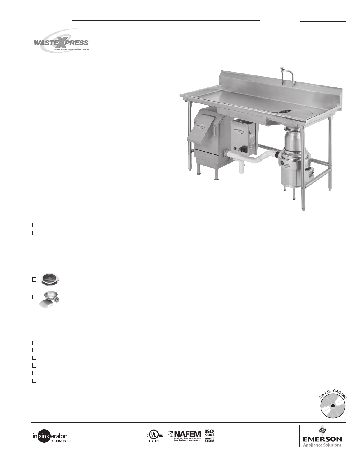
FOOD WASTE REDUCTION SYSTEM
PRODUCT FEATURES & SPECIFICATIONS
• Up to 85% volume reduction
• Capacity 700 lbs ( 317.5 kg) of waste per hour
• Fits under standard table – minimum height 34" (863.6 mm)
• Does not require cardboard
• Stainless steel construction
• Quick and easy to clean – no tools required
• One year full warranty
• Processes 100% food waste or up to 50% disposables
• NEMA 4 stainless steel electrical control panel
• Removeable auger and screen
• Interlock on discharge chute
• Water usage 2-5 GPM (7.6-18.9 LPM) – sink or
bowl configuration
• Trough application – contact factory
ELECTRICAL SPECIFICATIONS
WX-8 – 208-230V, 60 Hz, 3 Ph, 7.7/9.4 amps (Disposer 6.0/7.4 amps, WX 1.7/2 amps)
WX-9 – 460V, 60 Hz, 3 Ph, 4.7 amps (Disposer 3.7 amps, WX 1 amp)
DISPOSER MOUNTING ASSEMBLIES
#6 Collar Adaptor for welding into trough or sink, provides 6-5/8" (168.3 mm) opening, includes splash baffle
18" Type A Sink Bowl Assembly with two water nozzles, includes removable splash baffle and stainless bowl cover
ACCESSORIES
Reel Rinse Spray Unit (Fisher #2980)
Pre-Rinse Spray with wall bracket (Fisher #2010-WB)
Pre-Rinse Spray with wall bracket - Ultra Spray (1.6 GPM) (6.1 LPM) (Fisher #2010-1WB)
Trough Nozzle - 1" (25.4 mm) NPT
WXP Inlet/Outlet Flange - 2" (50.8 mm) NPT (secondary) (Trough or high water flow applications)
Dejamming Wrench
4700 21st STREET
RACINE, WI 53406-5093
TEL: 800-845-8345
FAX: 262-554-3620
www.insinkerator.com
InSinkErator is a division of Emerson Electric Co.
Our products appear on The KCL CADalog
CD-ROM based CAD Foodservice Symbol
Library. More information is available from
Kochman Consultants, Ltd. at www.kclcad.com.
The Emerson logo is a trademark and a
service mark of Emerson Electric Co.
InSinkErator ©2008 Printed in USA Form No. F269-08J-45-02
Page 2
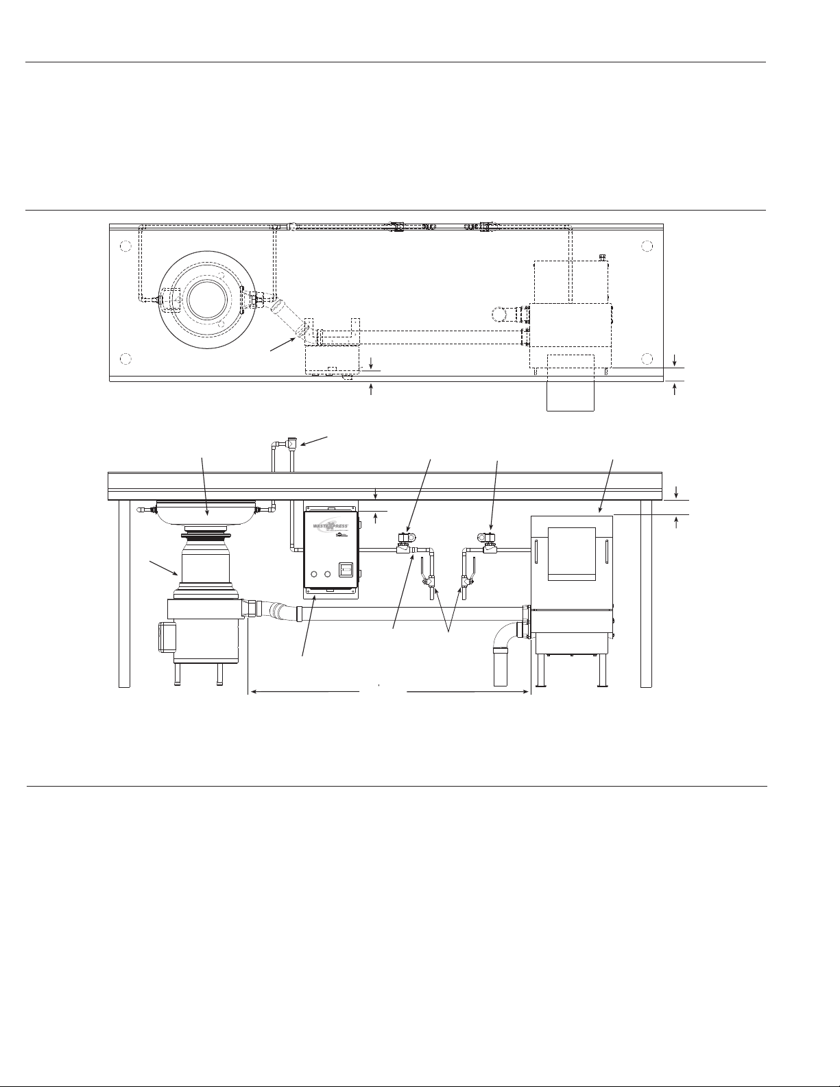
Flow Control Valve
Disposer
Sink Bowl
Syphon Breaker
Cold Water Solenoid Hot Water Solenoid Waste Xpress
Shut Off Valve
(supplied
by others)
WX-101A Controller
10 max
(3.1 m max)
1-1/2" min
(38.1 mm
min)
1" min
(25.4 mm min)
SYSTEM COMPONENTS
45˚ bend shown
(max of 4 can be used)
3"
(76.2 mm)
1-1/2"
(38.1 mm)
This System Includes:
• Waste Xpress Unit
• 3 HP Disposer
• Disposer mount (collar or bowl)
• Syphon Breaker
• Flow Control Valve 5 GPM
(18.9 LPM)
TYPICAL INSTALLATION
Figure 1. Waste Xpress Top View
• Magnetic Silver Saver
• 10 gallon (37.9 liter) Waste Can
• 3" (76.2 mm) to 2" (50.8 mm) disposer waste
outlet reducer fitting
• (2) 24V Water Solenoids
• WX-101A Control Center
Items Supplied by Others:
• Plumbing from cold water supply to bowl or trough
• Plumbing from hot water supply to Waste Xpress
• Plumbing from disposer to Waste Xpress or
Waste Xpress to floor sink or floor drain
• Shut off valves
• Electrical connections
Figure 2. Waste Xpress Typical Installation
GENERAL NOTES
Disposer
• Install the disposer per the Instruction, Care and Use manual.
• When positioning disposer ensure that the overload reset
button is accessible by end user.
• Connect cold water to either the sink bowl or end of trough.
Waste Xpress
• Install the Waste Xpress per the Instruction, Care and
Use manual.
• Position the pulper so that the front surface of the discharge
chute is recessed 3" (76.2 mm) (see Figure 1) from the front
edge of the table and that a minimum clearance of 1" (25.4 mm)
exists between the underside of the table and top of the
discharge chute (see Figure 2) for proper removal of discharge
chute, ease of cleaning and general maintenance.
• Position the pulper so that it is within 10' (3.1 m) of the
disposer outlet flange. (See Figure 2)
• The Waste Xpress should be disassembled and cleaned a
minimum of once daily. Interior of cabinet and discharge chute
should be cleaned with hot soapy water. Auger, screen and
bearing bracket can be cleaned either manually with hot soapy
water or in a dishwasher.
Control Panel
• Install the WX-101A control panel per the Instruction, Care and
Use manual and in accordance to local, state and or national
electric codes.
• Position the control panel so that the front surface is recessed
1-1/2" (38.1 mm) from the front edge of the table and that a
minimum clearance of 2" (50.8 mm) exists between the underside
of the table and the top of the control panel for ease of installation
and serviceability.
• Position the WX-101A control panel so that it is within site of the
disposer and pulper.
Page 3

Trough Flow
Water Nozzle
Recommended
Magnet Location
Optional Magnet Location
Connect Cold Water Supply
1" min
(25.4 mm min)
1" (25.4 mm) min,
3" (76.2 mm) max
to end of Trough
PLUMBING NOTES
Waste Connection
• 2" (50.8 mm) NPT – used between disposer, Waste Xpress
and drain
• When connecting the drain line from the disposer to the
Waste Xpress use a maximum of (4) 90° bends (45° bends
are recommended) with a 1/4" (6.4 mm) drop per foot of run
or as local codes apply.
• Floor sink or drains should be installed per local codes but
kept clear of yet accessible to pulper.
• Trough applications in excess of 10' (3.1 m) and/or systems
plumbed with a cold water supply greater than 7 GPM
(26.5 LPM) must incorporate the second drain outlet from the
pulper and be drained independently to floor sink or drain.
TROUGH APPLICATION NOTES
Construction
• The recommended maximum trough length is 10' (3.1 m).
• A silver saver should be fabricated prior to end of trough to
catch utensils and dishes.
Water Supply
• For trough lengths of 10' (3.1 m) or less place water nozzle at
end of trough.
• For trough lengths greater than 10' (3.1 m) place one
water nozzle at end of trough and one mid stream.
• Do not plumb water to disposer grind chamber.
Fresh Water Connections
• 1/2" (12.7 mm) NPT – used on syphon breaker, solenoid and
flow control valve.
• 1/2" (12.7 mm) NOM compression – used on sink bowl nozzles.
• 1/2" (12.7 mm) Ridged Copper (compression) – used on hot
water connection to pulper.
• If fresh water supply is greater than 50 psi (144.7 kPa), a
pressure regulating valve must be installed in both.
• It is recommend that ball type shutoff valves be installed
in the cold and hot water lines.
• It is recommended that the hot water connected between
solenoid valve and pulper be terminated with a union for
ease of serviceability.
Magnet
• Can be mounted to trough either by tack welding to using weld
studs (see instruction sheet for weld stud pattern).
• Trough magnets should be placed within 12" (304.8 mm) of
end of trough or trough intersection with sink bowl (see Figure 4).
• Additional magnets can be used as necessary.
Figure 3. Trough Typical Installation Top View
Figure 4. Trough Typical Installation
Page 4

21-3/4"
(552.5 mm)
21-1/8"
(536.6 mm)
26-7/8"
(682.6 mm)
33-1/2"
(850.9 mm)
8"
(203.2 mm)
27-3/8"
(695.3 mm)
7-7/8"
(200.0 mm)
Electrical Connection Cover
14-1/2"
(368.3 mm)
8-1/8"
(206.4 mm)
15"
(381 mm)
18-3/4"
(476.3 mm)
1-5/8"
(41.3 mm)
Waste Xpress Top View
15-1/8"
(384.2 mm)
14"
(355.6 mm)
15-3/4"
(400.1 mm)
9-7/8"
(250.8 mm)
8-1/4"
(209.6 mm)
Control Center Front View
Waste Xpress Side View
9-1/8"
(231.8 mm)
1/2"
(12.7 mm)
Electrical Inlet
1/2"
(12.7 mm)
Hot Water Inlet
Waste Xpress Back View
12-1/8"
(308.0 mm)
2"
(50.8 mm)
NPT Outlet
(Either Side)
2"
(50.8 mm)
NPT Inlet
(Either Side)
Leveling Foot
Adjustment Range
2-3/4"
(69.9 mm)
Waste Xpress Front View
8-5/8"
(219.1 mm)
Disposer Front View
External Electrical
Connection Cover
2"
(50.8 mm)
NPT Outlet
Adjustable Legs
Disposer Side View
8-3/4"
(222.3 mm)
8-3/4"
(222.3 mm)
13"
(330.2 mm)
23-3/4"
TO
31-1/8"
(603.3 mm
TO
790.6 mm)
6-1/2"
(165.1 mm)
Control Center Side View
5-1/4"
(133.4 mm)
5-5/16"
(134.9 mm)
6-3/4"
(171.5 mm)
1"
(25.4 mm)
DIMENSIONS
PROJECT INFORMATION
Item Number:
Quantity:
InSinkErator
Manufacturer:
City/State/Zip:
Project:
Address:
Contact:
Phone :
Installer:
Contact:
Phone :
Model Number:
Electrical
Requirements:
Dealer:
City/State/Zip:
Contact:
Phone :
Consultant:
Contact:
Phone :
volts phase
 Loading...