

Page 1
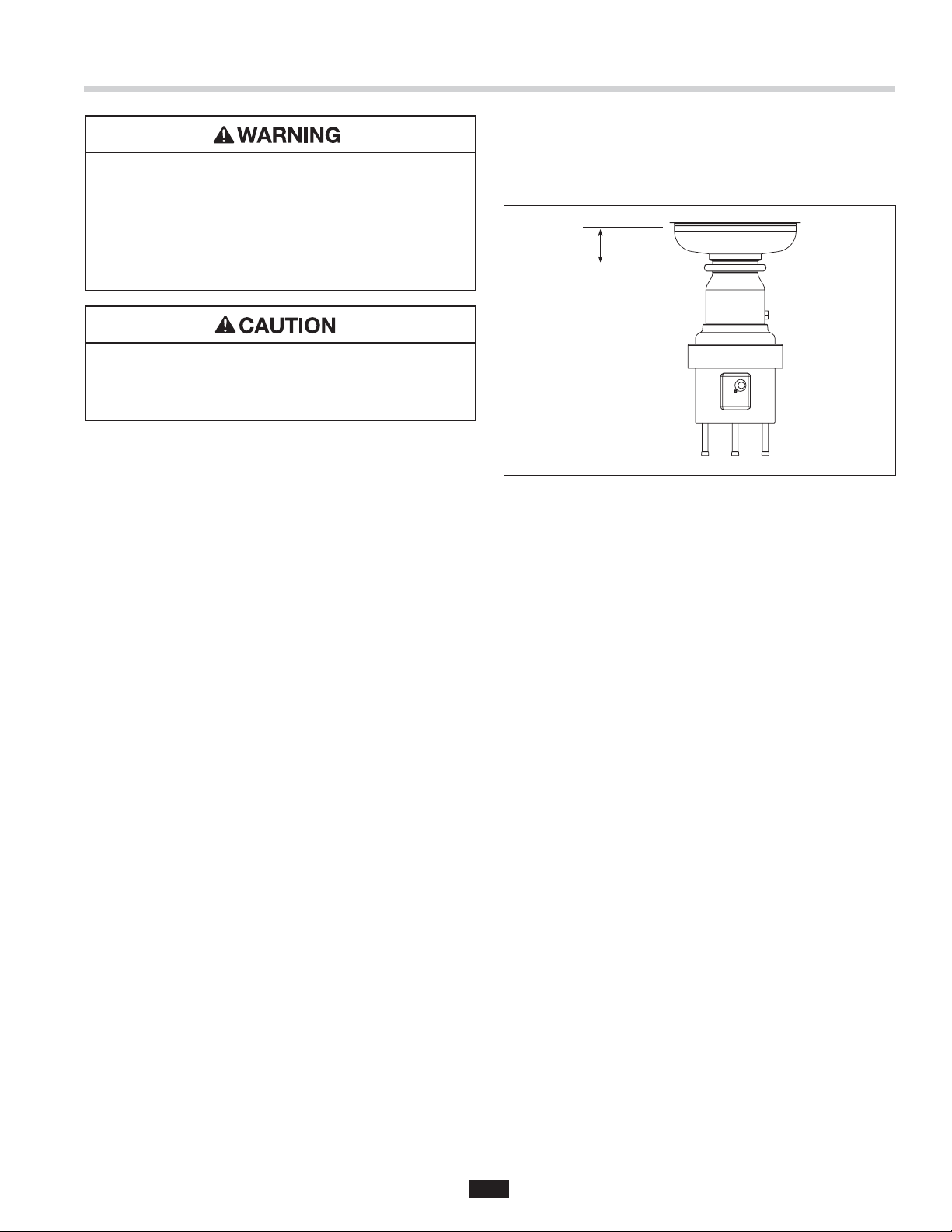
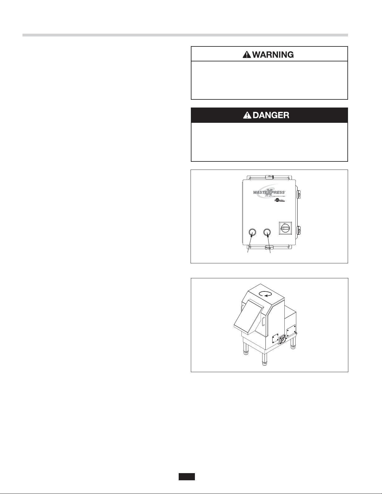
The Danger signal indicates an immediately hazardous situation which,
if not avoided, will result in death or serious injury.
The Warning signal alerts you to potential hazards or unsafe practices which,
if not avoided, could result in severe personal injury or death.
The Caution signal alerts you to hazards of unsafe practices which, if not avoided,
may result in minor personal injury or property damage.
Please be certain that the person who installs or uses this appliance carefully
reads and understands the Safety Instructions contained in this manual.
Part No. 14481 - May 2006www.insinkerator.com
Page 2

Table of Contents
Warranty ......................................................................................................... 4
Introduction/Typical Installation
Introduction ..................................................................................... 4
Typical Installation ........................................................................... 4
Waste Xpress Features ................................................................................. 5
WX-101A Control Features/Mounting Control Center
Introduction ..................................................................................... 6
Typical Installation ........................................................................... 6
Installing Disposer ......................................................................................... 7
InSinkErator Mounting Assemblies
Standard Mounting ......................................................................... 8
Special Mounting ............................................................................ 8
Installing Waste Xpress
Waste Xpress Diagrams .................................................................. 9
Installing Waste Xpress ................................................................. 10
Electrical Connections .................................................................. 10
Plumbing Connections
Waste Inlet Line ............................................................................. 11
Reverse Auger Screen................................................................... 11
Change Waste Inlet ....................................................................... 11
Waste Outlet Line .......................................................................... 12
Plumbing Connections .................................................................. 12
Water Supply Connection ............................................................. 12
Routing Water Flow ....................................................................... 12
Electrical Connections ................................................................................ 13
Operating Instructions
Pre-Operating ................................................................................ 14
Operating Instruction .................................................................... 15
Operating Waste Xpress System .................................................. 16
Operational Tips ............................................................................ 16
Cleaning Instruction .................................................................................... 17
Troubleshooting
System Troubleshooting ................................................................ 18
Disposer Troubleshooting ............................................................. 20
Waste Xpress Troubleshooting ...................................................... 21
Wiring Diagrams
Model No. WX-101A-1 (120V, 1 phase) ......................................... 22
Model No. WX-101A-2 (208/230V, 1 phase) ................................. 24
Model No. WX-101A-3 (208/230V, 3 phase) ................................. 26
Model No. WX-101A-4 (380/460V, 3 phase) ................................. 28
Motor Wiring Diagrams ............................................................................... 30
3
3
Page 3
Warranty
WASTE XPRESS SYSTEM LIMITED WARRANTY
The InSinkErator® Waste Xpress®, disposer and control centers are warranted against defects in material and
workmanship for one year from the date of installation. The warranty includes parts and labor, provided an
InSinkErator Factory Authorized Service Center performs the service. This warranty does not apply if the failure
is due to: faulty or improper electrical installation, faulty or improper plumbing installation, product abuse or
misuse, accidental damage, clogged drain lines, improperly sized unit (as specifi ed by InSinkErator).
Introduction/Typical Installation
INTRODUCTION
The InSinkErator® Waste Xpress® is a Foodservice
kitchen waste reduction system that utilizes a standard
Foodservice disposer in line with the Waste Xpress
dewatering system. The kitchen waste is ground
through the disposer then transferred to the Waste
Xpress where it is compressed. After the waste is
compressed, the liquids are sent down the drain line
and the solid waste exiting the Waste Xpress is 85%
less in volume (see Figure 1 for typical installation).
Important – These installation instructions are for
the benefi t of the installing contractor. InSinkErator
and/or InSinkErator Factory Authorized Service
Centers do not make original installations. For technical
information not covered in these instructions,
contact the supplier, an InSinkErator Field Sales
Representative, or InSinkErator Foodservice Sales
and Service at 1-800-845-8345.
Syphon
Breaker
Sink Bowl
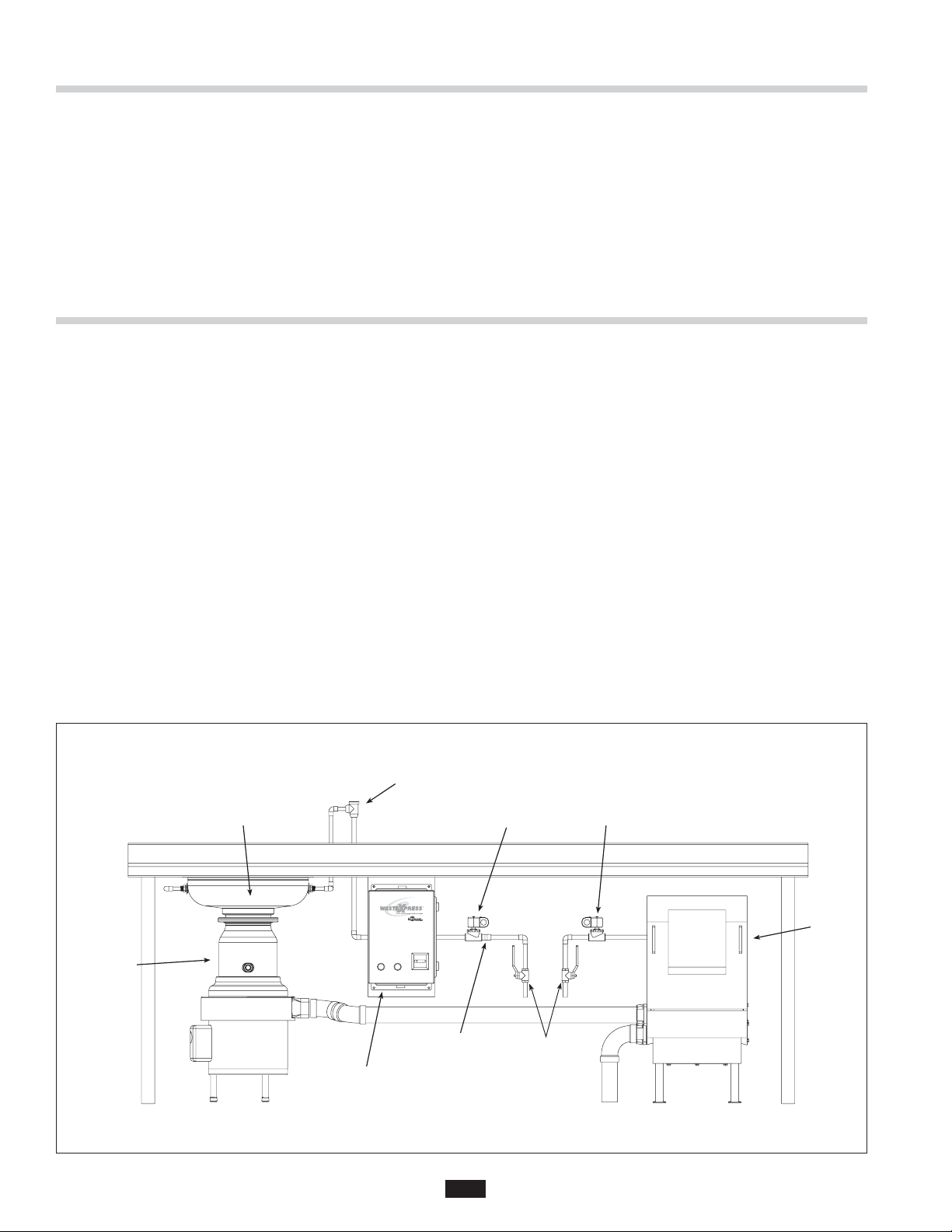
TYPICAL INSTALLATION
A typical Waste Xpress installation incorporates the
following connections (see Figure 1):
• Waste Xpress
• Disposer
• Control Center
• Syphon breaker
• Solenoid valves (2)
• Water shut off valve
• Bowl or trough
• Flow control valve
• Cold water (sink or trough)
• Hot water (Waste Xpress)
Cold Water
Solenoid
Hot Water
Solenoid
Disposer
Figure 1. Typical Installation
WX-101A
Controller
Flow Control
Valve
4
Shut Off
Valve
Waste
Xpress
Page 4
Waste Xpress Features
FEATURES
COMPACT SIZE
The Waste Xpress® is designed to fi t under a 34" high
commercial kitchen table.
WASTE REDUCTION
Reduces volume by 85%.
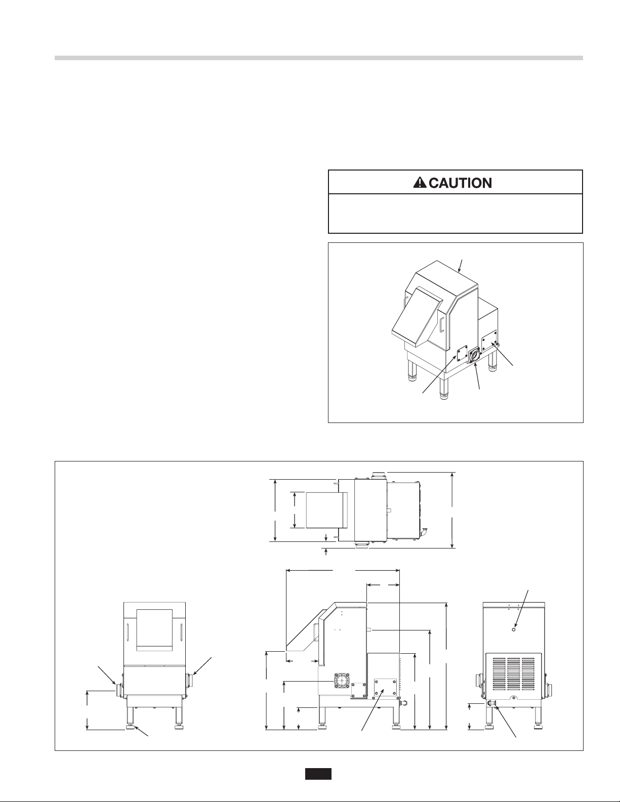
SAFETY INTERLOCK
The Waste Xpress is equipped with safety interlock
on the discharge chute (see Figure 2). This interlock
prevents the system (disposer & Waste Xpress) from
operating unless the discharge chute is properly seated.
DRAIN CONNECTIONS
• Water outlet should be routed directly to a fl oor drain
(and as close to the Waste Xpress as possible).
• The 2" NPT waste inlet connection can be mounted
on either side.
• The 2" NPT water outlet connection can be mounted
on either side.
• For trough or high water fl ow applications, connect
both Water Outlet connections for optimum
cabinet drainage.
• All drain lines must be a minimum 2" NPT in diameter.
CONSTRUCTION
Stainless steel construction (for physical size see
Figure 3).
WASTE MIX
The Waste Xpress can process non-food waste such
as paper, light and rigid plastic or food wrappings when
mixed with a minimum of 50% food waste.
PROPERTY DAMAGE
Plastic wrap, cans, silverware, rubber, glass and
crockery cannot be processed.
Safety Interlock
Terminal
Connection
Waste Inlet
(either side)
Waste Outlet
(either side)
2" NPT Outlet
(Either Side)
12 1/8"
9 3/8"
2" NPT Inlet
(Either Side)
Leveling Foot
Adjustment Range 2 3/4"
21 3/4"
19"
15"
14 1/2"
11 3/4"
8 5/8"
8 1/8"
5 3/8"
Figure 2.
1 5/8"
7 7/8"
Electrical Connection Cover
27 3/8"
18 1/4"
8"
33 1/2"
30 3/4"
26 7/8"
24 1/8"
21 1/8"
18 3/8"
9 1/8"
6 3/8"
1/2" Hot Water Inlet
1/2" Electrical Inlet
Figure 3. Waste Xpress Dimensions
5
Page 5
WX-101A Control Features/Mounting Control Center
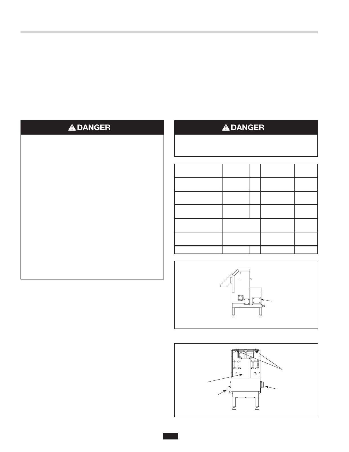
The WX-101A Control Center is UL® approved for use
with InSinkErator Waste Xpress food waste reduction
systems. The control center operates the disposer and
Waste Xpress. Its main functions are:
• To start and stop the disposer/Waste Xpress system.
• To reverse the direction of the disposer motor
automatically upon restart.
• To start the water fl ow to the disposer.
• To allow water fl ow for several minutes to fl ush the
drain line after the disposer is turned off.
Model Part No. Voltage Phase
WX-101A-1 14479 120V 1
WX-101A-2 14479A 208/230V 1
WX-101A-3 14479B 208/230V 3
WX-101A-4 14479C 380/460V 3
Table 1. Electrical Specifi cations
FEATURES
SINGLE BUTTON OPERATION
Disposer and Waste Xpress are controlled by simple
ON/OFF button operation.
AUTOMATIC REVERSE
The disposer motor will reverse its direction of
rotation automatically upon restart. To avoid motor
damage, a delay feature prevents reversing until
the post fl ush is complete.
ELECTRICAL SHOCK
• Ensure that Waste Xpress voltage and phase match
that of the electrical supply, control center &
disposer. Check nameplate for specifi cation.
• Electrical connections should be made by a
qualifi ed electrician and should comply with all
local codes.
• Turn off electrical supply to Waste Xpress,
control center & disposer before attempting to
work on it. Test with a volt meter or circuit tester
to ensure that power is off.
• Do not operate unit with panels removed.
• All components (disposer, WX, control center
and solenoids) must be carefully and permanently
grounded.
• A properly fused disconnect must be installed at
Waste Xpress, control center & disposer electrical
supply source.
• Use only NEMA 4 watertight electrical connectors
when connecting to junction box.
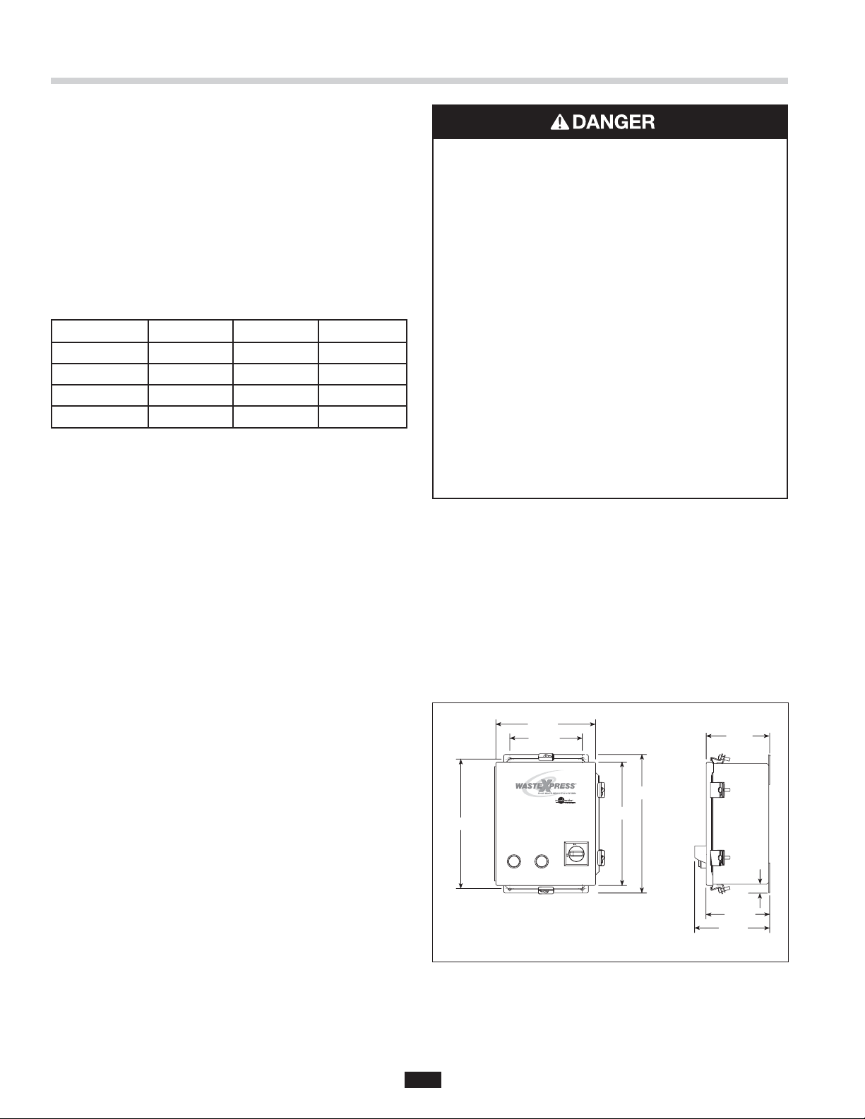
MOUNTING THE CONTROL CENTER
Use the fl anges at the back of the control center
enclosure and only mount panel in the upright vertical
position (door hinge is on the left). See Figure 4.
Locate control center within sight of disposer per
local codes.
WATER SHUTOFF DELAY (POST FLUSH)
After the motor is turned off, the water continues to
fl ow for up to 10 minutes. The length of this post fl ush
is controlled by the water shutoff delay timer. The post
fl ush helps ensure that ground food waste is fl ushed
out of the drain line.
AUTOMATIC TIMED DISPOSER SHUTOFF
This water saving feature allows the system to run for
10 minutes before it automatically shuts off and must
be manually restarted.
LINE DISCONNECT SWITCH
The switch on the front panel of the control center
disconnects the line voltage. It interlocks with the front
cover so that the cover cannot be opened unless the
switch is in the off position.
LOW VOLTAGE CONTROL
Control operates on a 24 V solid state control circuit.
ENCLOSURE
Stainless steel NEMA 4 construction.
WX TIMER HOT WATER SPRAY ADJUSTABLE
Factory set for 2 minutes off 10 second on controls hot
water spray for cleaning of screen.
If box is mounted to the sink table, recess the box so
that the buttons do not extend beyond the table’s edge
(see Figure 4).
9 7/8"
8 1/4"
15 1/8"
Figure 4. Control Center Dimensions
14"
15 3/4"
5 1/4"
1"
5 5/16"
6 3/4"
6
Page 6
Installing Disposer
PERSONAL INJURY
• For safe operation, The minimum required distance
from the table top or trough to the mounting fl ange
is 6 inches for standard body disposers
(as specifi ed by UL). See Figure 5.
• Moving shredder parts may cause serious injury if
a hopper or cone is not properly installed.
PROPERTY DAMAGE
To avoid excess vibration, InSinkErator
recommends a minimum countertop thickness
of 16 gage stainless steel.
DISPOSER MOUNTING
The disposer can be mounted to the sink or trough
using a standard InSinkErator mount or an
InSinkErator mounting adaptor.
CLEAN THE DRAIN LINE
With a drain line auger, clear away all hardened waste
material in the horizontal drainpipe running from the
drain trap to the main waste line.
6 inch min.
Figure 5.
NOTE: The InSinkErator #5 Sink Flange can not be
used with the Waste Xpress system.
NOTE: InSinkErator must approve attachment to a
non-InSinkErator sink.
7
Page 7
InSinkErator Mounting Assemblies
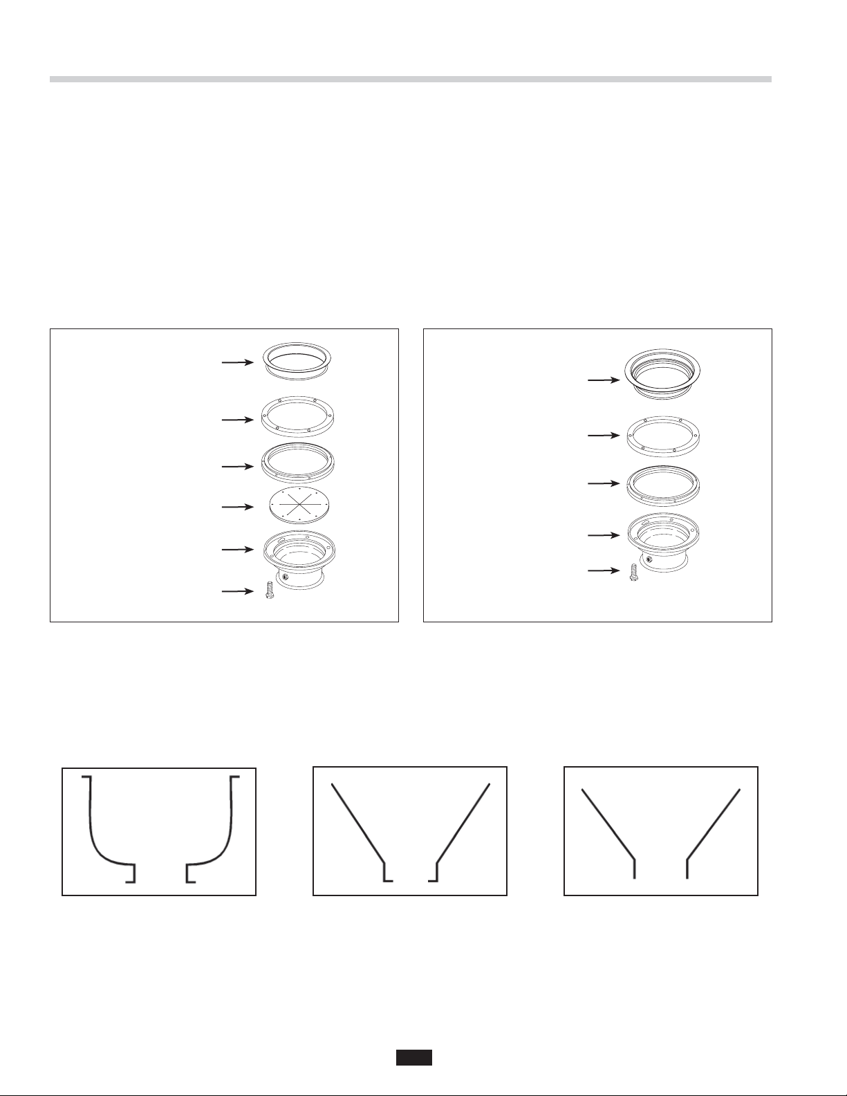
STANDARD MOUNTING ASSEMBLY
1. Place mounting fl ange (1) over the existing collar
adaptor connection lip or sink bowl fl ange (this may
require some force).
2. Push the mounting fl ange up out of the way and fi t
the groove in the mounting gasket (2) onto the
connection lip. Make sure the gasket is fully seated
on the fl ange.
3. Push the mounting fl ange down over the mounting
gasket, fi tting the threaded mounting fl ange fasteners
into the recesses in the top of the mounting gasket.
#6 Collar Adaptor
(1) Mounting Flange
(2) Mounting Gasket
(3) Flat Gasket
4. From the bottom, insert two screws through opposite
sides of the fl at gasket (3) and mounting fl ange, into
the threaded fasteners in the existing fl ange. The
fl at gasket is used only in the #6 mounting assembly.
The screws should protrude about 1/4 inch below the
mounting gasket.
5. Position the disposer beneath the mounting gasket
and raise it to engage the two protruding screws in
the disposer body fl ange keyhole slots. Secure the
remaining screws and position the disposer correctly
for the plumbing connections. If disposer legs are
included, adjust the legs to support the disposer.
#7 Collar Adaptor
(1) Mounting Flange
(2) Mounting Gasket
Disposer Body Flange
Disposer Body Flange
1/4” Screw
1/4” Screw
Figure 6. #6 Mounting Assembly Figure 7. #7 or Sink Bowl Mounting Assembly
SPECIAL INSINKERATOR MOUNTING ASSEMBLIES
When installing an InSinkErator Foodservice disposer to a non-InSinkErator sink bowl, a special mounting adaptor
kit is required. The special mountings are described in the Mounting Adaptor Selection Guide (for more information,
call 1-800-845-8345 or go to www.insinkerator.com). Figures 8-10 show examples of non-InSinkErator style sinks.
(Mounting instructions are included in each special mounting adaptor kit.)
Figure 8. Outward Flange Figure 9. Inward Flange Figure 10. Straight Flange
8
Page 8
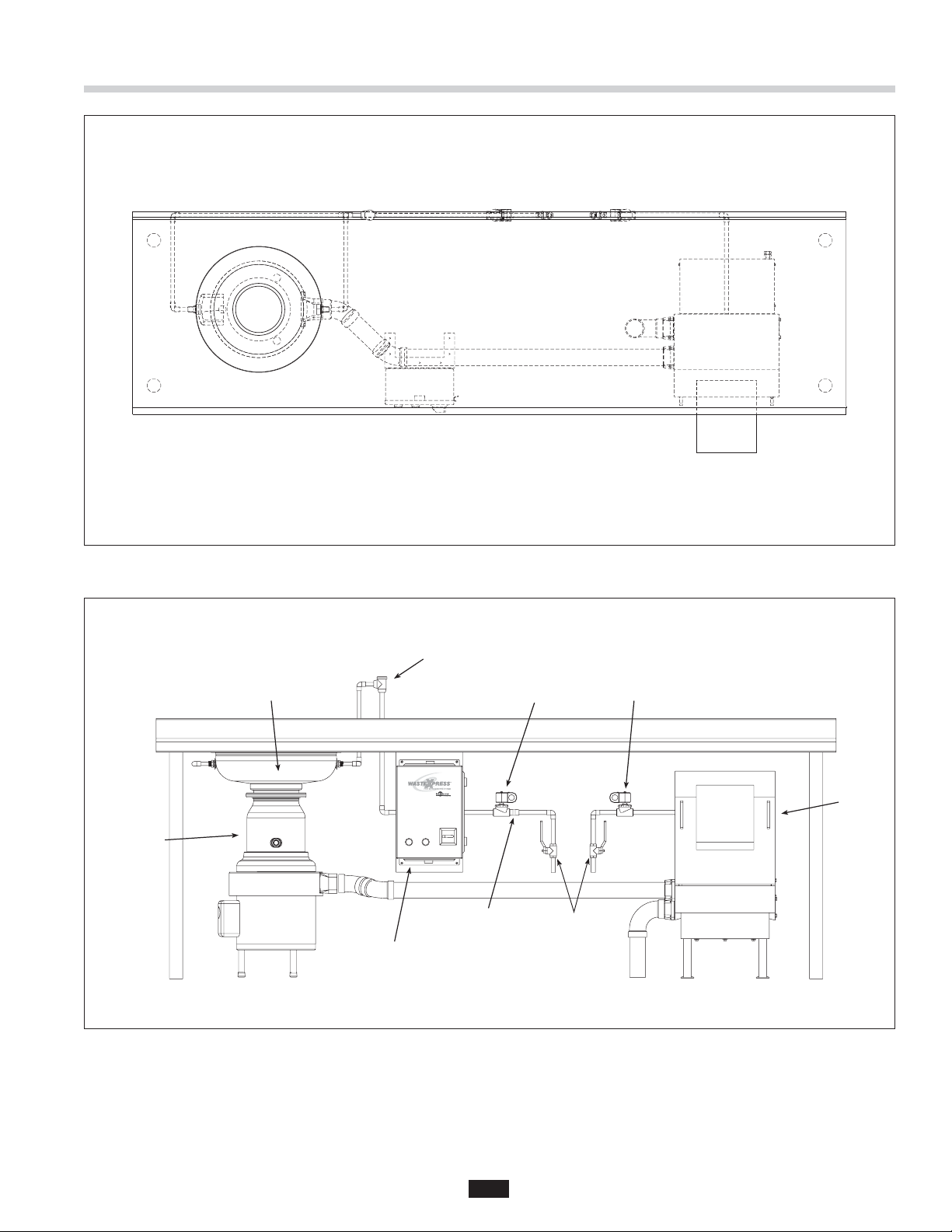
Installing the Waste Xpress
Figure 11. Top View
Disposer
Sink Bowl
WX-101A
Controller
Syphon
Breaker
Flow Control
Valve
Cold Water
Solenoid
Shut Off
Valve
Hot Water
Solenoid
Waste
Xpress
Figure 12. Typical Installation Diagram
9
Page 9
Installing the Waste Xpress
WASTE XPRESS LOCATION
NOTE: Prior to installing the Waste Xpress the
disposer and control center should be installed as
specifi ed within this manual.
• Position Waste Xpress within 10 feet of the disposer
outlet fl ange. A maximum of four (4) 90º elbows can
be used between the disposer and Waste Xpress
(prefer 45º elbow).
• Level Waste Xpress by turning the legs in or out
with a wrench. Place a level on top of the unit.
ELECTRICAL SHOCK
• Ensure that Waste Xpress voltage and phase match
that of the electrical supply, control center &
disposer. Check nameplate for specifi cation.
• Electrical connections should be made by a
qualifi ed electrician and should comply with all
local codes.
• Turn off electrical supply to Waste Xpress,
control center & disposer before attempting to
work on it. Test with a volt meter or circuit tester
to ensure that power is off.
• Do not operate unit with panels removed.
• All components (disposer, WX, control center
and solenoids) must be carefully and permanently
grounded.
• A properly fused disconnect must be installed at
Waste Xpress, control center & disposer electrical
supply source.
• Use only NEMA 4 watertight electrical connectors
when connecting to junction box.
7. Connect wire bundle between WX-101A and
Waste Xpress unit as detailed in wiring diagram.
Door interlock connections are #3 and #95. Replace
terminal cover.
8. Wire per local electrical codes and install
using NEMA 4 watertight electrical connectors
(not supplied).
9. Install disposer terminal box cover and secure with
retaining screw.
10. Secure WX-101A cover with locking clamps.
ELECTRICAL SHOCK
Do not pinch or damage the electrical wires when
installing the terminal box.
WX
Terminal
WX Auger Motor
1 Phase
WX Auger Motor
3 Phase
WX Magnetic
Interlock
Cold Water Solenoid
(Disposer)
Hot Water Solenoid
(WX Spray)
Disposer To See Diagrams Line
T1, T2 To T1, T2 Line
T1, T2, T3 To T1, T2, T3 Line
3, 95 To 3, 95 24V
WX-101A
Terminal
4, 13 24V
7, 18 24V
Voltage
ELECTRICAL CONNECTIONS
The Waste Xpress system requires power only to the
control center. The control center powers the disposer
and Waste Xpress.
1. Remove retaining screw and disposer
electrical cover.
2. Open control center cover by loosening locking
clamps securing it.
3. Remove terminal cover from Waste Xpress
(see Figure 13).
4. Connect incoming power line to electrical door
disconnect switch in WX-101A.
5. Connect disposer motor leads to terminal
block locations.
6. Connect cold water solenoid to appropriate
terminals 4 and 13. Connect hot water solenoid to
terminal 18 and 7.
Figure 13.
Auger
Screen
Waste Outlet
Figure 14. Cover Removed
10
Terminal
Cover
Captive
Fasteners
Waste Inlet
Page 10

Plumbing Connections
PROPERTY DAMAGE
Water connections must comply with all local
plumbing codes.
WASTE INLET LINE
Connect the disposer outlet fl ange as close as
possible and with as few as possible 90° elbows to
the Waste Xpress inlet.
NOTE: The maximum allowable distance between the
disposer outlet fl ange and the Waste Xpress inlet is
10 feet with a maximum of four (4) 90° elbows.
1. Connect the disposer outlet to the Waste Xpress
inlet using 2" NPT plumbing. 3 HP will require 3"
outlet adapter. The run between the disposer and
Waste Xpress should have 1/4" slope per foot and
must comply with all local codes.
NOTE: All horizontal runs should be as short as
possible (not to exceed 10 ft.), with an approximate
fall of 1/4" per foot.
TO REVERSE AUGER SCREEN:
A. Holding both handles remove discharge chute
of the Waste Xpress by tilting it upward
(see Figure 13).
B. Remove auger-bearing bracket by sliding the two
captive fasteners inward and then pull
bracket upward (see Figure 14).
C. Lift auger and screen up and then out
(see Figure 14).
D. Remove auger from screen by lifting up
(see Figure 15).
E. Remove four nuts and washers holding the top
portion of the auger screen to the bottom portion
(see Figure 16).
F. Rotate bottom portion of the auger screen 180°
and secure to top portion with four nuts and
washers (see Figure 17).
Figure 15.
Figure 16.
Figure 17.
Inlet
Nuts &
Washer (4)
Auger
Screen
TO CHANGE WASTE INLET SIDE ON
WASTE XPRESS:
A. Remove four screws holding inlet fi tting and gasket
in position (see Figure 18).
B. Remove four screws holding the cap and gasket in
position (see Figure 18).
C. Install gaskets, cap and inlet fi tting on reverse side
and secure with appropriate screws.
Figure 18.
11
Waste
Outlet
Waste
Inlet
Page 11

Plumbing Connections
WASTE OUTLET LINE
Connect a 2" drain line to the Waste Xpress waste
outlet as specifi ed per local codes (see Figure 18
for water outlet location).
InSinkErator recommends that the water outlet
empties into a fl oor drain.
If the water outlet connection on the Waste Xpress
needs to be switched to the other side, complete
the following:
• Remove the four screws holding the cap and gasket in
position (see Figure 18).
• Install gasket, cap and inlet fi tting on reverse side
and secure with appropriate screws.
NOTE: The Waste Xpress system should not be
plumbed directly into a small inside grease trap.
The unit can be plumbed through a large exterior
grease trap.
PLUMBING CONNECTIONS
The syphon breaker is supplied with all Waste Xpress
systems (packed separately).
Syphon breaker must be installed above the sink fl ood
plane per local plumbing codes. Check direction of
water fl ow arrows.
The solenoid valve is supplied with a 24 V coil.
• The fl ow control valve regulates all cold water fl owing
into the disposer and Waste Xpress. This conserves
water and prevents overloading.
WATER SUPPLY CONNECTIONS
When connecting the incoming water supply to the
disposer, sink bowl and Waste Xpress, use as few
elbows and tees as possible.
All cold water line fi ttings are 1/2" NPT except the
sink bowl nozzles which are 1/2" compression.
Use 1/2" compression fi tting to connect hot water
to Waste Xpress.
Install the fl ow control valve, water solenoid valve,
and syphon breaker according to the direction of the
arrows marked on each valve body.
NOTE: In-line hot and cold shutoff valves are
recommended close to the Waste Xpress system
for ease of service.
ROUTING WATER FLOW
Connect cold water only to disposer, bowl, or trough.
Connect hot water only to Waste Xpress for hot water
spray nozzles.
In a trough system, route all water fl ow to the end of
the trough to fl ush food waste.
PROPERTY DAMAGE
System has hot water spray that must be
connected. Fresh water connection to the
Waste Xpress must be hot water only. Failure
to use hot water may clog system and result
in malfunction.
Sink Bowl
Disposer
Figure 19. Typical Installation Diagram
WX-101A
Controller
Syphon
Breaker
Flow Control
Valve
12
Cold Water
Solenoid
Shut Off
Valve
Hot Water
Solenoid
Waste
Xpress
Page 12

Electrical Connections
ELECTRICAL SHOCK
• Turn off all electrical supply to the disposer before
attempting any work on it. Use a voltmeter or
circuit tester to ensure that power is off.
• All Installation work must conform to local
plumbing and electrical codes.
• All components (disposer, WX, control center
and solenoids) must be carefully and permanently
grounded.
• A properly fused disconnect must be installed at
the electrical supply source for the control center.
• The control center’s door disconnect must be in the
off position before the panel door can be opened.
Power is still present at the disconnect until power
is turned off at the electrical supply source.
LINE VOLTAGE
Connect the incoming line power to the electrical
disconnect switch and connect the disposer motor to
labeled terminal blocks in the control center. Use the
appropriate voltage and phase wiring diagram(s) in
the Wiring Diagram section at the end of this manual.
A wiring diagram is also located on the inside door of
the control center. Wire the disposer motor for correct
voltage using the connection diagram inside the motor
terminal box.
PROPERTY DAMAGE
• Ensure that control center voltage and phase
match the disposer motor and electrical supply.
Check nameplates on disposer and control
center for voltage and phase specifi cations.
• Refer to the control center wiring diagrams in
this manual for correct connection.
• Use NEMA 4 watertight electrical connectors
(not supplied) when making electrical connections
to the control center.
COLD WATER SOLENOID VALVE
One 24 V cold water solenoid valve is supplied with
control centers. Connect solenoid valve to terminals 4
and 13. Supplied fl ow control valve is to be connected
to cold water line.
Wire per local electrical code using NEMA 4 water-tight
electrical connections.
HOT WATER SOLENOID VALVE
One 24 V hot water solenoid valve is supplied with
control centers. Connect solenoid valve to terminals 7
and 18. No fl ow control valve is to be used on hot water
line. Use 1/2" compression fi tting to connect hot water
line to Waste Xpress.
LOW VOLTAGE
The WX-101A control center uses low voltage (24 V)
to operate contactor coils, solid state control circuit,
push buttons, and solenoid valves. Red wires denote
a 24 V circuit.
PERSONAL INJURY
Disconnect electricity at line disconnect switch
before servicing system.
13
Page 13
Operating Instructions
PRE-OPERATION TEST
Before operating the Waste Xpress complete
the following steps to ensure the unit has been
properly installed.
1. Ensure plumbing and electrical connections
are secure.
2. Turn on incoming cold water supply to disposer
and hot water supply to the Waste Xpress.
3. Check to make sure auger and screen are seated on
auger drive hub, positioned correctly, and fasteners
on upper bearing bracket are installed and engaged
correctly prior to starting.
4. Ensure that the discharge chute is fi tted securely
in position.
5. Turn on incoming power to disposer and
Waste Xpress.
NOTE: Use of the electrical door disconnect knob on
the WX-101A control panel will result in a 30 second
delay before the system can be restarted. You must
wait 30 seconds after reactivation of the line disconnect
switch before system will restart.
PERSONAL INJURY
If system does not shut down when front
cover/discharge chute is removed, interlock may
not be wired correctly. See Troubleshooting section
for corrective action.
ELECTRICAL SHOCK
Turn off electrical supply to Waste Xpress, control
center and disposer before attempting to work on
it. Test with a volt meter or circuit tester to insure
that power is off.
6. Push start button on the control center
(see Figure 20). The WX-101A and disposer will run
and cold water will fl ow into the disposer.
7. Observe auger rotation by looking up into discharge
chute; auger should rotate clockwise (when viewed
from above). See Figure 21.
NOTE: If auger rotates counter-clockwise, turn off main
power supply, wait 60 seconds, then restart. If auger
continues to rotate counter-clockwise (when viewed
from above), unit must be re-wired. Turn off main power.
On three phase Waste Xpress interchange leads L1 and
L2. Restart.
8. Make sure cold water is fl owing into disposer.
9. Make sure hot water to Waste Xpress spray nozzles
is cycling. Factory set cycle is 10 seconds on and
2 minutes off.
10. Press stop button to stop disposer and
Waste Xpress. Steam from chute should be evident.
11. Restart system and remove front cover/discharge
chute. Waste Xpress and disposer should turn
off automatically if interlock switch is functioning
properly. Water will continue to fl ow into disposer.
Start Stop
Figure 20.
Rotation of Auger
Figure 21.
12. Replace front cover/discharge chute and
restart system.
14
Page 14

Operating Instructions
TO START
1. Check to ensure disposer is free of foreign objects.
2. Ensure power is on.
3. Push start button. Disposer and Waste Xpress will run
and water will fl ow into disposer
TO STOP
1. Push stop button. System will stop.
2. Water may continue to fl ow into disposer for up to
10 minutes, per the time set on the water shutoff
delay timer. This post-fl ush clears the drain lines
of food waste.
WATER SHUTOFF DELAY ADJUSTMENT
This water shutoff delay is adjustable from 30 seconds
to 10 minutes (see Figure 23). Set water shutoff delay
for at least 2 minutes on trough systems.
PERSONAL INJURY
To adjust the water shutoff delay, disconnect the
electrical power to the control panel and open the
control center door.
Locate the water shutoff delay at the top of the printed
circuit board in the WX-101A (see Figure 22). Set the dip
switches for the desired water shut off delay. Use the
guide printed on the circuit board to set minutes of
delay (also see Figure 23). The dip switches should be
moved to match the fi lled in areas of the guide.
NOTE: Line disconnect should not be turned off
between usage.
AUTOMATIC TIMED DISPOSER SHUTOFF
This water saving feature allows the system to run for
10 minutes before it automatically shuts off and must
be manually restarted.
NOTE: This feature is set in the manual position at
the factory. To activate the automatic timed system
shutoff, disconnect the electric power to the control
center, then open the control center door. Locate the
Dip Switch Module at the top of the circuit board (see
Figure 22). Move the #5 dip switch from MANUAL to
AUTOMATIC. The system now automatically shuts off
10 minutes after it starts.
Figure 22.
30 Second Delay:
Dip Switches 1, 2,
3, pushed down,
Switch 4 pushed
1
up.
234
10 Minute Delay:
Dip Switches 1,
3, 4 pushed up
position, Switch 2
pushed down
Figure 23. Time Delay Setting Examples
1
234
MANUAL
AUTOMATIC
MANUAL
AUTOMATIC
15
Page 15

Operating Instructions
OPERATING WASTE XPRESS SYSTEM
1. Make sure there are no foreign objects in disposer
grind chamber. Do not pre-load disposer with food
waste prior to starting.
2. Place 10 gallon waste bin under discharge chute.
3. Push start button on control center. Waste Xpress
and disposer will run and water will fl ow into disposer.
4. Feed food waste into disposer in a steady,
continuous fl ow. Waste will exit discharge chute
and drop into waste bin.
NOTE: Once all waste has been fed into disposer, allow
approximately 2 minutes for system to clear. This will
allow system to fl ush itself prior to system shutdown.
5. Press Stop button to stop system.
PROPERTY DAMAGE
Do not insert: string, metal, glass, cans, silverware,
dishes, cloth napkins or large quantities of grease
or oil into the disposer.
PERSONAL INJURY
Do not dispose of hot liquids such as grease, oil
and syrup into disposer.
OPERATIONAL TIPS
• Ensure a steady stream of cold water runs into the
disposer while it is operating.
• Do not overload the disposer or turn it off with food
waste inside the grind chamber (run the disposer
and water for three minutes after the fi nal load to
fl ush away all food waste).
• Clean auger and auger screen, bearing bracket, and
discharge chute daily by running through dishwasher.
Start Stop
Figure 24.
16
Page 16

Cleaning Instructions
PERSONAL INJURY
Wait until auger paddles stop before cleaning
Waste Xpress.
1. Press stop button on control center to stop system
(disposer & Waste Xpress).
2. Holding both handles remove discharge chute by
tilting it upward (see Figure 25).
3. Remove auger-bearing bracket by sliding the two
captive fasteners inward and then pull bracket
upward (see Figure 26 and 27).
4. Lift auger and screen up and then out
(see Figure 26).
5. Remove auger from screen by lifting it up and out
(see Figure 28).
6. Rinse auger, screen, auger compartment and
discharge chute. Auger, screen and discharge
chute are dishwasher safe and should be washed
daily. Flush inlet and outlet with a fresh water
supply to keep the drain lines clean.
7. Install auger into screen then place screen
over drive.
8. Ensure that the auger drops into position.
Discharge
Chute
Figure 25.
Auger Screen
Figure 26.
Captive
Fasteners
9. Secure bearing bracket with captive fasteners.
10. Install discharge chute by placing bottom, front
portion in fi rst and then tilting back and downward.
Figure 27. Bearing Bracket
Figure 28.
17
Page 17

Troubleshooting
ELECTRICAL SHOCK
• Disconnect power before servicing.
• Do not bypass interlock switch.
Wait until auger paddles stop before servicing
Waste Xpress.
PERSONAL INJURY
Troubleshooting for problems other than what is listed below should be performed by a qualifi ed service person.
Troubleshooting performed by untrained personnel could result in electrical shock or damage to the Waste Xpress,
disposer and/or Control Center.
SYSTEM TROUBLESHOOTING
PROBLEM POSSIBLE CAUSE SOLUTION
The Waste Xpress, disposer and
water do not turn on.
• Electrical supply turned off.
• Fuse blown or circuit breaker
tripped at power supply.
• Discharge chute of Waste Xpress not
seated properly
• Waste blocking safety interlock.
• Control circuit fuse (FNA2) blown.
• 24 volt power from control center
not present.
• Turn on electrical supply.
• Replace fuse or reset circuit breaker.
• Reinstall chute to ensure proper fi t.
• Remove waste from safety interlock.
• Replace fuse.
• Call for service.
The disposer will not start or stops
while grinding, but the Waste Xpress
and water operate properly.
The Waste Xpress, disposer and
water appear to run however
no solid waste is ejected from
the discharge chute of the
Waste Xpress.
Water backs up into
disposer (does not drain).
• The disposer overload
protector tripped.
• The disposer jammed.
• Auger is not suffi ciently primed with
waste after cleaning.
• Insuffi cient waste in waste line.
• Auger turning in wrong direction.
• The auger and screen plugged.
• Auger not turning.
• Plumbing line between disposer and
Waste Xpress clogged.
• Press stop button on control center and
press red reset button on disposer.
Note: you may need to let disposer cool
down before setting.
• Press stop button on control center and
follow direction for dejamming
(supplied with disposer).
• Allow unit to run longer to prime itself.
• Waste will exit when more waste is added.
• Three phase - Switch leads L1 and L2.
• Remove plug.
• Ensure that auger is seated properly and
that auger belt in place. Check motor.
• Remove clog.
18
Page 18

PROBLEM POSSIBLE CAUSE SOLUTION
Waste Xpress stops unexpectedly.
Troubleshooting
SYSTEM TROUBLESHOOTING
• Discharge chute misaligned.
• Reinstall discharge chute to ensure
proper fi t.
Water exits Waste Xpress
at front of cabinet.
Waste Xpress does not run,
but disposer and water run.
No water spraying onto
auger screen.
Water fl ows continuously before
controls are turned on.
• Fuse blown or circuit breaker
tripped at power source.
• Stop button on control center
has been pushed.
• Drain line has clog.
• High water level.
• Contactor defective.
• Auger motor defective.
• Solenoid valve clogged.
• Water turned off.
• Solenoid valve defective.
• Spray nozzles clogged.
• Timer defective.
• Timer not set properly.
• Solenoid valve installed incorrectly.
• Solenoid valve installed incorrectly.
• Replace fuse or reset circuit breaker.
• Push start button on control center.
• Clear drain.
• Add second waste outlet drain connect from
Waste Xpress cabinet to sewer connection
(recommended for trough applications).
• Call service.
• Call service.
• Remove clog.
• Turn on water.
• Call service.
• Replace nozzles.
• Call service.
• Call service.
• Reinstall solenoid valve so arrow is pointing
in correct direction.
• Reinstall the water solenoid valve with the
arrow on the valve pointing in the direction
of the water fl ow.
Overload protector trips frequently.
• Timer is not set properly.
• Solenoid valve is defective.
• Disposer is overloaded with
food waste.
• Call service.
• Replace solenoid valve.
• Do not overload disposer with excessive
amounts of food waste.
19
Page 19

PROBLEM CAUSE SOLUTION
Disposer motor will not start and
water does not fl ow.
Troubleshooting
DISPOSER TROUBLESHOOTING
• No incoming line power
• Line disconnect switch is not ON
• Turn line power on.
• Turn line disconnect to ON position.
Disposer does not reverse direction.
Disposer motor stops while grinding
but water continues to fl ow.
Disposer will not start but
water fl ows.
• Line disconnect switch has been
reactivated and 30-second delay has
not yet expired.
• Control circuit fuse FNA2 is blown.
• Control center has been reactivated
before post-fl ush delay has expired.
• Control center wired for
automatic shut-off.
• Disposer is jammed.
• Disposer motor overload protector
has tripped.
• Overload protector on the disposer
may have tripped.
• Wait 30 seconds and try starting again.
• Replace fuse.
• Wait until post-fl ush is complete and
try again.
• Press start button. If disposer runs for
10 minutes then shuts off, the automatic
shutoff is active. If the manual setting is
desired, change indicated in the
feature section.
• Press stop button and follow directions for
dejamming in disposer installation manual.
• Press stop button. Locate red reset button
on front of disposer electrical cover.
Press to reset. If motor had been running,
wait fi ve minutes for the motor and overload
to cool down.
• Press stop button. Locate red reset button
on front of disposer electrical cover. Press
to reset. If motor had been running, wait
fi ve minutes for the motor and overload to
cool down.
Water fl ows constantly before start
button is pushed.
Overload trips frequently.
• Disposer is jammed
• Water solenoid valve is
installed backward.
• Press stop button and follow directions
for dejamming that were supplied with
the disposer.
• Water fl ow should be in the direction of the
arrow on valve.
• Disposer overloaded. • Do not overload disposer with excess
amounts of garbage and water.
20
Page 20

PROBLEM POSSIBLE CAUSE SOLUTION
Auger runs in Counterclockwise
(CCW) direction.
Troubleshooting
WASTE XPRESS TROUBLESHOOTING
• Power to auger motor reversed. • Reverse motor leads to auger motor or
switch L1 and L2 connections on WX
terminal block. Auger must run in
Clockwise direction.
Unit does not shut off with cover off
of Waste Xpress unit.
• Waste Xpress Interlock not
operating properly.
• Check interlock switch #3 and #95
connections on WX-101A to WX.
• Call service
Hot Water Spray is cold.
Hot Water spray does not work.
Auger reverses direction on
each re-start.
Waste Xpress unit will not start.
Water Shuts off when unit shuts off.
If the Waste Xpress remains inoperative after following this troubleshooting guide, contact InSinkErator’s service department at
1-800-845-8345 for the location of the nearest approved service agency.
• Incorrectly plumbed.
• No hot water.
• Connect solenoid on WX unit to hot
water source.
• Ensure hot water heater/source
is functioning.
• Incorrectly wired. • Check connections on WX-101A #7 to
WX #18.
• Waste Xpress unit auger motor
has been wired into disposer
motor circuit.
• Incorrect wiring.
• Misaligned Interlock switch on chute.
• Improper dipswitch setting
(circuit board).
• Re-wire as shown in instructions.
• Check wiring.
• Check chute for tight fi t.
• Refer to Page 14 to refer to dipswitch
setting instructions.
21
Page 21

Waste Xpress 120V, 1Phase System Wiring Diagram
ELECTRICAL SHOCK
• Turn off the electrical supply to the disposer before
attempting any work on it. Use a voltmeter or
circuit tester to ensure that power is off.
• Installation must conform to local electrical codes.
• All components (disposer, WX, control center
and solenoids) must be carefully and permanently
grounded.
• A properly fused disconnect must be installed at
the electrical supply source for the control center.
120 V
1-phase
PROPERTY DAMAGE
• Ensure that the control center voltage and phase
match the disposer motor and electrical supply.
Check nameplates on disposers and control
centers for voltage and phase specifi cation.
• The disposer motor wiring connection is shown in
the disposer terminal box.
Call Toll Free 1-800-845-8345
for the nearest InSinkErator
Authorized Service Agency or
to reach Technical Support.
22
Page 22

WX101A-1 120V, 1Phase Electrical Connections
23
Page 23

Waste Xpress 208/230V, 1Phase System Wiring Diagram
ELECTRICAL SHOCK
• Turn off the electrical supply to the disposer before
attempting any work on it. Use a voltmeter or
circuit tester to ensure that power is off.
• Installation must conform to local electrical codes.
• All components (disposer, WX, control center
and solenoids) must be carefully and permanently
grounded.
• A properly fused disconnect must be installed at
the electrical supply source for the control center.
208/230 V
1-phase
PROPERTY DAMAGE
• Ensure that the control center voltage and phase
match the disposer motor and electrical supply.
Check nameplates on disposers and control
centers for voltage and phase specifi cation.
• The disposer motor wiring connection is shown in
the disposer terminal box.
Call Toll Free 1-800-845-8345
for the nearest InSinkErator
Authorized Service Agency or
to reach Technical Support.
24
Page 24

WX101A-2 208/230V 1Phase Electrical Connections
25
Page 25

Waste Xpress 208/230V, 3Phase System Wiring Diagram
ELECTRICAL SHOCK
• Turn off the electrical supply to the disposer before
attempting any work on it. Use a voltmeter or
circuit tester to ensure that power is off.
• Installation must conform to local electrical codes.
• All components (disposer, WX, control center
and solenoids) must be carefully and permanently
grounded.
• A properly fused disconnect must be installed at
the electrical supply source for the control center.
120 V
208/230 V
1-phase
3-phase
1/2 to 2 HP
PROPERTY DAMAGE
• Ensure that the control center voltage and phase
match the disposer motor and electrical supply.
Check nameplates on disposers and control
centers for voltage and phase specifi cation.
• The disposer motor wiring connection is shown in
the disposer terminal box.
Call Toll Free 1-800-845-8345
for the nearest InSinkErator
Authorized Service Agency or
to reach Technical Support.
26
Page 26

WX101A-3 208/230V 3Phase Electrical Connections
27
Page 27

Waste Xpress 380/460V, 3Phase System Wiring Diagram
ELECTRICAL SHOCK
• Turn off the electrical supply to the disposer before
attempting any work on it. Use a voltmeter or
circuit tester to ensure that power is off.
• Installation must conform to local electrical codes.
• All components (disposer, WX, control center
and solenoids) must be carefully and permanently
grounded.
• A properly fused disconnect must be installed at
the electrical supply source for the control center.
120 V
380/460 V
1-phase
3-phase
1/2 to 2 HP
PROPERTY DAMAGE
• Ensure that the control center voltage and phase
match the disposer motor and electrical supply.
Check nameplates on disposers and control
centers for voltage and phase specifi cation.
• The disposer motor wiring connection is shown in
the disposer terminal box.
Call Toll Free 1-800-845-8345
for the nearest InSinkErator
Authorized Service Agency or
to reach Technical Support.
28
Page 28
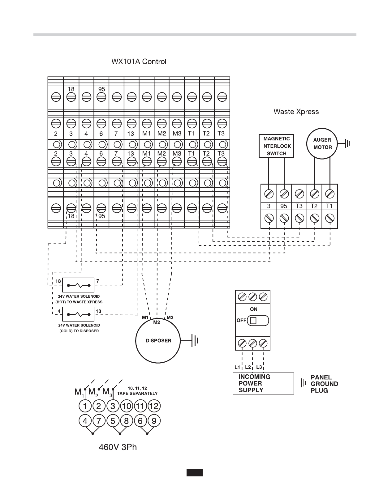
WX101A-4 380/460V 3Phase Electrical Connections
29
Page 29

Figure 29. 208-230 volt - 3 Phase
460 volt - 3 Phase
Motor Wiring Diagrams
Figure 30. 115 volt - 1 Phase
208-230 volt - 1 Phase
30
Page 30

 Loading...