

Page 1
SERVICE MANUAL
DANGER indicates an imminently hazardous situation which, if not avoided, will
(WX-1, WX-2, WX-3, WX-4)
DANGER
WARNING
result in death or serious injury.
WARNING indicates a potential hazardous situation which, if not avoided, could
result in death or serious injury.
CAUTION indicates a potentially hazardous situation which, if not avoided, may
CAUTION
result in minor or moderate injury.
Ensure that the person servicing the Mini Waste Xpress carefully reads and understands the
safety instructions in this manual.
Part No. 14272 April 2000
Page 2

MINI WASTE REDUCTION SYSTEM LIMITED WARRANTY
The In-Sink-Erator Mini Waste Xpress, disposer and control centers are warranted against detects in material and workmanship for one year
from the date of installation. The warranty includes parts and labor, provided an In-Sink-Erator Factory Authorized Service Center performs
the service. This warranty does not apply if the failure is due to: faulty or improper electrical installation, faulty or improper plumbing
installation, product abuse or misuse, accidental damage, clogged drain lines, improperly sized unit (as specified by In-Sink-Erator).
Page 3

Table of Contents
Introduction 1
Defining Problems 2
Testing & Replacing
Discharge Interlock Assembly 3, 4
Replacing auger Paddles 5
Replacing Tension Adjustment Dial 6
Replacing Tension Spring 7
Replacing Auger Weight 8
Replacing Auger 9
Replacing Screen 10
Replacing Spray Nozzle 11
Replacing Inlet/Outlet Fitting 12
Replacing Captive Fasteners 13
Replacing Retaining Spring 14
Replacing Auger Belt 15
Replacing Pulley 16
Replacing Auger Drive Assembly 17, 18
Replacing Auger Motor 19, 20
Replacing Motor Bracket 21
Replacing Solenoid Valve 22
Replacing Plumbing 23
Replacing Leveling Foot 24
Replacing Control Panel Components 25
Wiring Diagrams 26-33
Internal Motor Connections 34
Trouble shooting 35, 36
Page 4

Table of Contents
Introduction 1
Defining Problems 2
Testing & Replacing
Discharge Interlock Assembly 3, 4
Replacing auger Paddles 5
Replacing Tension Adjustment Dial 6
Replacing Tension Spring 7
Replacing Auger Weight 8
Replacing Auger 9
Replacing Screen 10
Replacing Spray Nozzle 11
Replacing Inlet/Outlet Fitting 12
Replacing Captive Fasteners 13
Replacing Retaining Spring 14
Replacing Auger Belt 15
Replacing Pulley 16
Replacing Auger Drive Assembly 17, 18
Replacing Auger Motor 19, 20
Replacing Motor Bracket 21
Replacing Solenoid Valve 22
Replacing Plumbing 23
Replacing Leveling Foot 24
Replacing Control Panel Components 25
Wiring Diagrams 26-33
Internal Motor Connections 34
Trouble shooting 35, 36
Page 5
Introduction
Figure
1-1
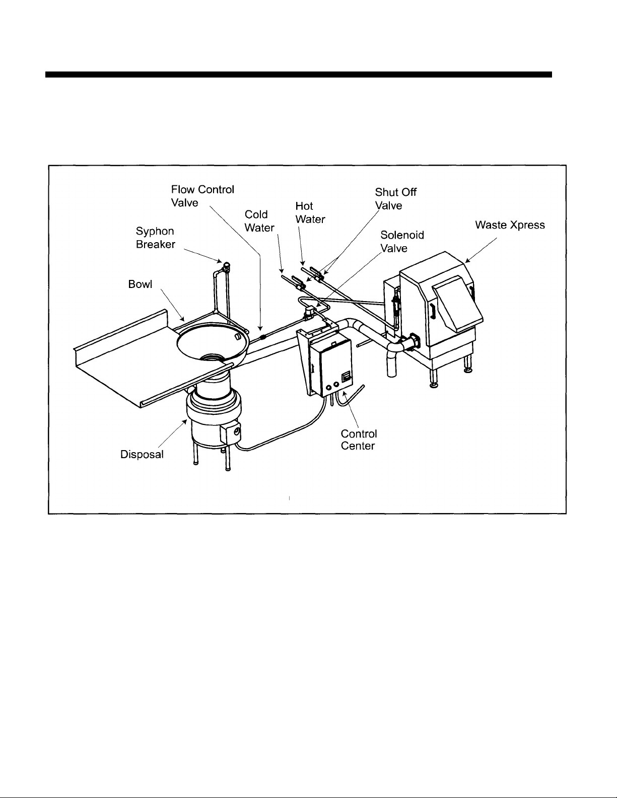
The In-Sink-Erator Mini Waste Xpress is a commercial kitchen waste reduction system that utilizes a standard commercial food waste disposer
inline with the Mini Waste Xpress dewatering system. The kitchen waste is ground through the disposer then transferred to the Mini Waste
Xpress where it is compressed. After the waste is compressed, the liquids are sent down the drain line and the solid waste exiting the Mini
Waste Xpress is 85% less in volume. (See figure 1 -1 for typical installation.)
PRIOR TO SERVICE CALL
• Obtain the model number, serial number, voltage and phase from the customer to prepare for the service
call.
• Check the service history of the Mini Waste Xpress.
• Make sure the customer has checked for foreign objects jammed in auger area (see troubleshooting).
1
Page 6

Defining Problems
DEFINING PROBLEMS
Before troubleshooting for mechanical problems, determine if the problem is electrical.
• Do the Mini Waste Xpress electrical specifications match those of the electrical power supply, control center and
disposer?
• Are the motor lead connections correct for the corresponding power supply?
• If the problem is electrical, determine if there are electrical problems with other kitchen appliances (this may indicate
a problem in the electrical circuitry of the building).
Are the water connections installed correctly?
A hot water supply should be connected to 1/2" copper tube water inlet as specified per local codes.
(In-Sink-Erator recommends installing a shut off valve close to unit).
AFTER COMPLETING SERVICE
Test the Mini Waste Xpress for proper operation and ensure that the fittings are secure and do not leak.
NOTE: Please references the Mini Waste Xpress Parts List (14273) for additional part identification when
servicing the Mini Waste Xpress.
2
Page 7
Testing & Replacing Discharge Chute Interlock Assembly
Figure
1-1
Figure
1-2 Figure
1 -3
DANGER
Electrical Shock
Failure to turn off the water and electrical
supply before servicing may result in product
damage or injury.
1. Turn off power to Mini Waste Xpress at fuse box or
circuit breaker. Turn off water supply to Mini Waste
Xpress.
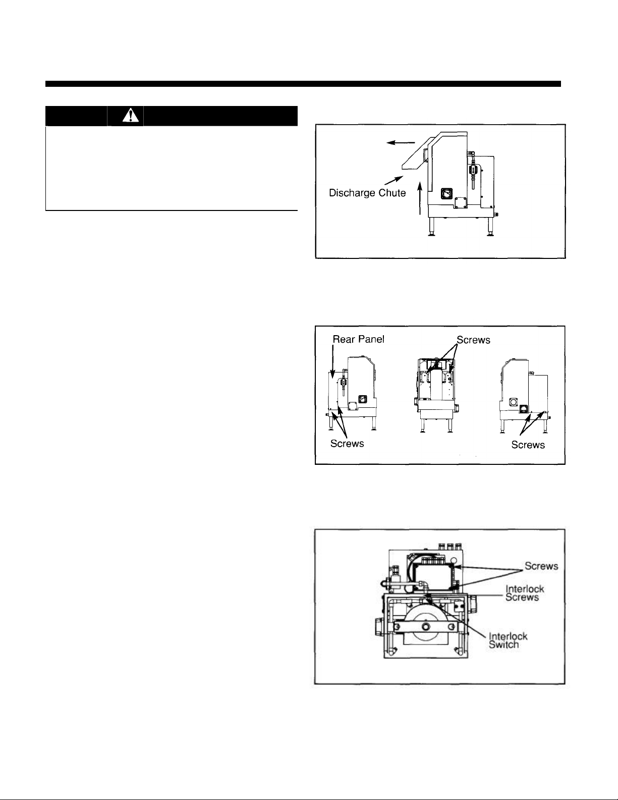
2. Holding both handles remove discharge chute by
tilting it upward (see figure 1-1).
3. Remove rear panel by removing the screws securing it
in place (see figure 1-2).
4. Remove control box cover by removing the
screws securing it in place (see figure 1-3).
5. Install discharge chute by placing bottom front portion
in first and then tilting back and downward.
6. With interlock assembly closed, test wires 6 & 7 for
continuity (see pages 26-33).
• If continuity reads closed, skip to step 18.
• If continuity reads open, replace interlock switch
assembly.
To replace interlock assembly:
7. Remove discharge chute.
8. Loosen strain relief on cord going from switch to
control box (see figure 1-3).
9. Remove wires 6 & 7 from control box.
10. Remove two screws securing interlock switch to
cabinet (see figure 1 -3).
11. Remove interlock switch.
12. Install new interlock switch, securing with two screws.
13. Insert wires 6 & 7 (from interlock switch) through strain
relief and into control box. Connect wires 6 & 7 to
terminal block (see pages 26-33) and tighten strain
reliefs.
3
Page 8
Figure
1-4
Testing & Replacing Discharge Chute Interlock Assembly (Cont.)
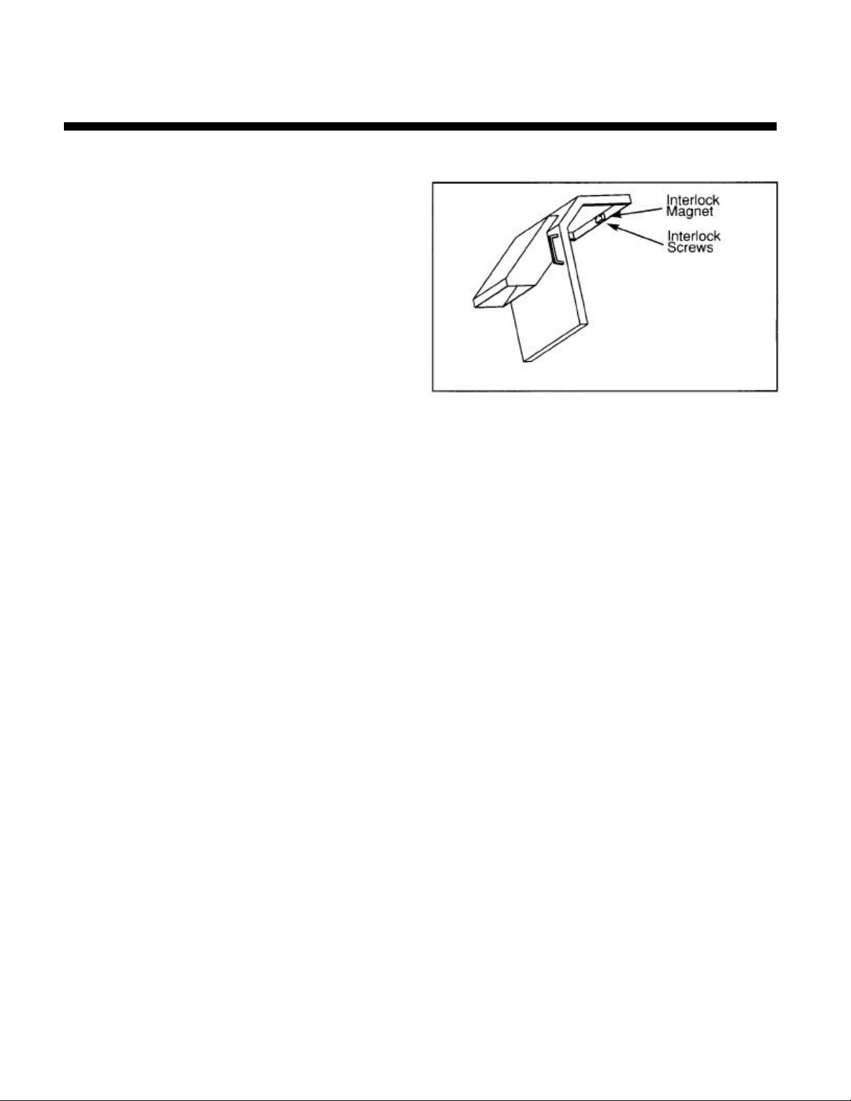
14. Unscrew two screws securing interlock magnet on
discharge chute and remove interlock magnet (see
figure 1 -4).
15. Install new interlock magnet and secure with two
screws.
16. Install discharge chute.
17. With interlock switch closed, test wires 6 & 7 for
continuity.
• If continuity reads closed, skip to step 18.
• If continuity reads open, rotate interlock magnet
180° on discharge chute and test for continuity
again.
18. Replace rear panel, control box cover and secure
with screws.
19. Turn on power to Mini Waste Xpress at fuse box or
circuit breaker. Turn on water supply to Mini Waste
Xpress.
4
Page 9
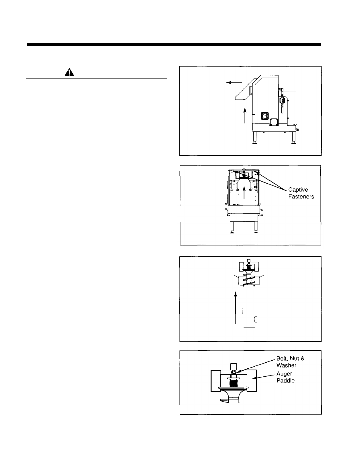
Replacing Auger Paddles
Figure
2-4 Figure
2-2
Failure to turn off the water and electrical
WARNING
Personal Injury
supply before servicing may result in product
damage or injury.
1. Turn off power to Mini Waste Xpress at fuse box or
circuit breaker. Turn off water supply to Mini Waste
Xpress.
2. Holding both handles remove discharge chute by tilting
it upward (see figure 2-1).
3. Remove auger-bearing bracket by turning the two
captive fasteners counter clockwise and then pull
bracket upward (see figure 2-2), replace if necessary.
4. Lift auger and screen up and then out.
5. Remove auger from screen by lifting up (see figure 2-
3).
6. Remove bolt, nut and washers securing auger paddle
to auger shaft (see figure 2-4).
7. Remove auger paddle from shaft.
8. Install new auger paddle and secure with bolt, nut and
washers.
9. Ensure auger weight travels freely up and down after
assembly.
10. Install auger into screen then place screen over drive.
11. Ensure that the auger drops into position.
12. Secure bearing bracket with captive fastener.
13. Install discharge chute by placing bottom front portion
in first and then tilting back and down ward.
14. Turn on power to Mini Waste Xpress at fuse box or
circuit breaker. Turn on water supply to Mini Waste
Xpress.
Figure 2-1
Figure 2-3
5
Page 10
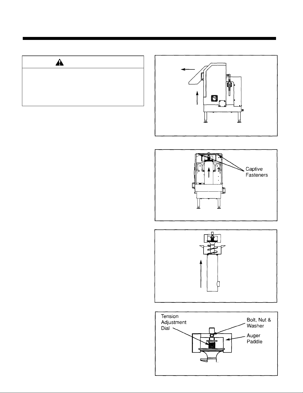
Replacing Tension Adjustment Dial
Figure
3-1
Figure
3-2 Figure
3-3
Figure
3-4
WARNING
Personal Injury
Failure to turn off the water and electrical
supply before servicing may result in product
damage or injury.
1. Turn off power to Mini Waste Xpress at fuse box or
circuit breaker. Turn off water supply to Mini Waste
Xpress.
2. Holding both handles, remove discharge chute by tilting
it upward (see figure 3-1).
3. Remove auger-bearing bracket by turning the two
captive fasteners counter clockwise and then pull
bracket upward (see figure 3-2), replace if necessary.
4. Lift auger and screen up and then out.
5. Remove auger from screen by lifting it up (see figure 3-
3).
6. Remove bolt, nut and washers securing auger paddle
to auger shaft (see figure 3-4).
7. Remove auger paddle (replace if necessary) and
tension adjustment dial from shaft.
8. Install new tension adjustment dial and auger paddle.
Secure auger paddle to shaft with bolt, nut and
washers.
9. Ensure auger weight travels freely up and down after
assembly.
10. Install auger into screen then place screen over drive.
11. Ensure that the auger drops into position.
12. Secure bearing bracket with captive fastener.
13. Install discharge chute by placing bottom front portion
in first and then tilting back and down ward.
14. Turn on power to Mini Waste Xpress at fuse box or
circuit breaker. Turn on water supply to Mini Waste
Xpress.
6
Page 11
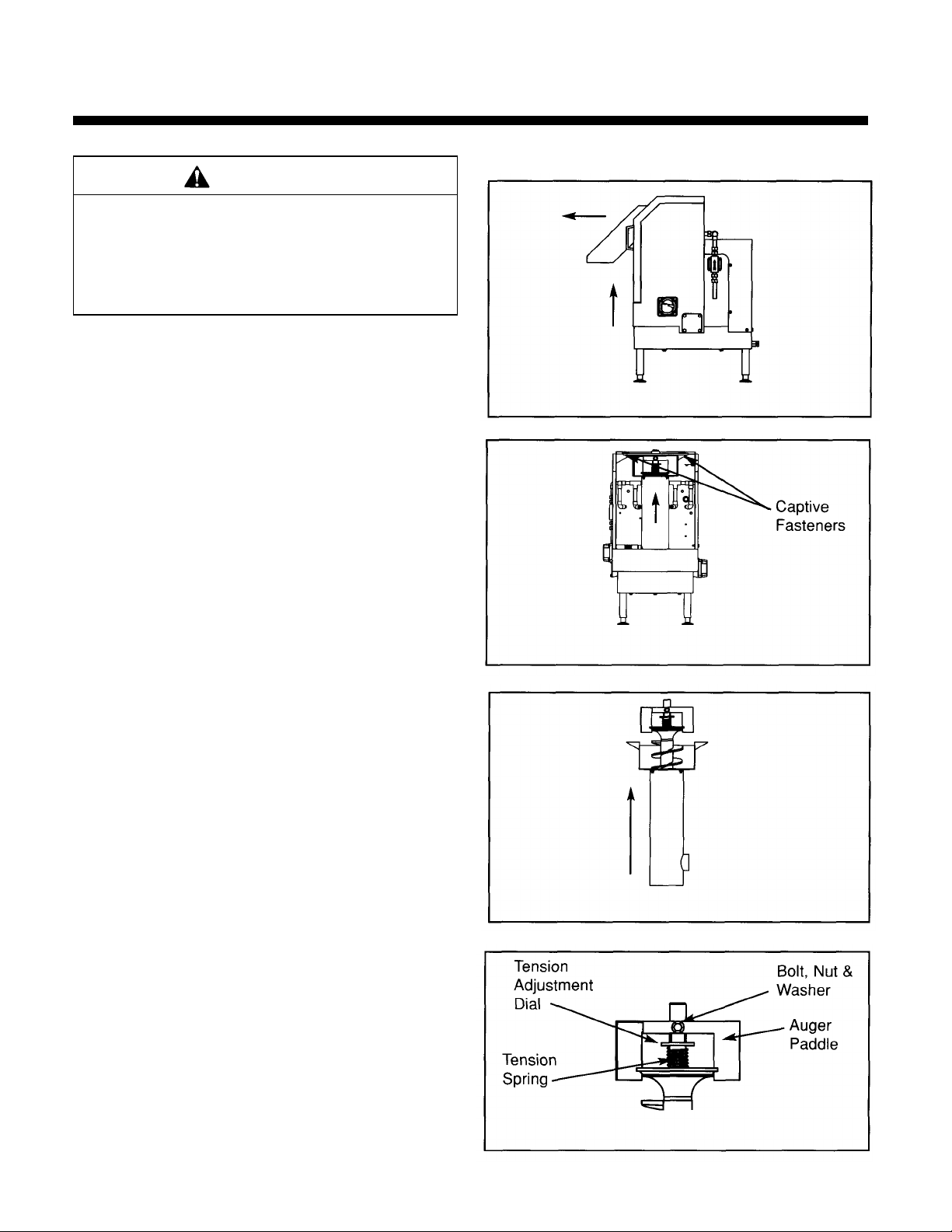
Replacing Tension Spring
damage or injury.
Figure
4-1 Figure
4-2 Figure
4-3 Figure
4-4
WARNING
Personal Injury
Failure to turn off the water and electrical
supply before servicing may result in product
1. Turn off power to Mini Waste Xpress at fuse box or
circuit breaker. Turn off water supply to Mini Waste
Xpress.
2. Holding both handles, remove discharge chute by tilting
it upward (see figure 4-1).
3. Remove auger-bearing bracket by turning the two
captive fasteners counter clockwise and then pull
bracket upward (see figure 4-2), replace if necessary.
4. Lift auger and screen up and then out.
5. Remove auger from screen by lifting it up (see figure 4-
3).
6. Remove bolt, nut and washers securing auger paddle
to auger shaft (see figure 4-4).
7. Remove auger paddle (replace if necessary), tension
adjustment dial (replace if necessary) and tension
spring from shaft.
8. Install new tension spring, tension adjustment dial and
auger paddle. Secure auger paddle to shaft with bolt,
nut and washers.
9. Ensure auger weight travels freely up and down after
assembly.
10. Install auger into screen then place screen over drive.
11. Ensure that the auger drops into position.
12. Secure bearing bracket with captive fastener.
13. Install discharge chute by placing bottom front portion in
first and then tilting back and downward
14. Turn on power to Mini Waste Xpress at fuse box or
circuit breaker. Turn on water supply to Mini Waste
Xpress.
7
Page 12
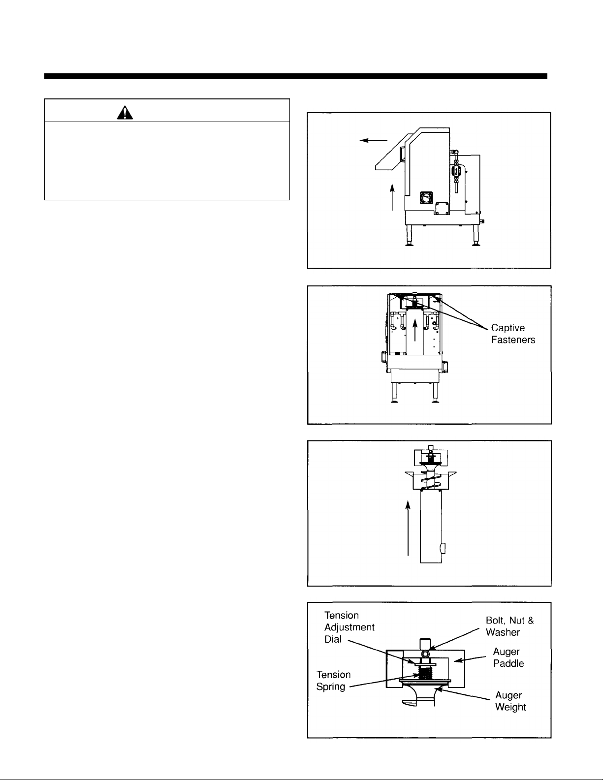
Replacing Auger Weight
Figure
5-2
Figure
5-3 Figure
5-4
WARNING
Personal Injury
Failure to turn off the water and electrical
supply before servicing may result in product
damage or injury.
1. Turn off power to Mini Waste Xpress at fuse box or
circuit breaker. Turn off water supply to Min Waste
Xpress.
2. Holding both handles, remove discharge chute by
tilting it upward (see figure 5-1).
3. Remove auger-bearing bracket by turning the two
captive fasteners counter clockwise and then pull
bracket upward (see figure 5-2), replace if necessary.
4. Lift auger and screen up and then out.
5. Remove auger from screen by lifting it up (see figure
5-3).
6. Remove bolt, nut and washers securing auger paddle
to auger shaft (see figure 5-4).
7. Remove auger paddle (replace if necessary), tension
adjustment dial (replace if necessary), tension spring
(replace if necessary) and auger weight from shaft.
8. Install new auger weight, tension spring, tension
adjustment dial and auger paddle. Secure auger
paddle to shaft with bolt, nut and washers.
9. Ensure auger weight travels freely up and down after
assembly.
10. Install auger into screen then place screen over drive.
11. Ensure that the auger drops into position.
12. Secure bearing bracket with captive fastener.
13. Install discharge chute by placing bottom front portion
in first and then tilting back and downward.
14. Turn on power to Mini Waste Xpress at fuse box or
circuit breaker. Turn on water supply to Mini Waste
Xpress.
Figure 5-1
8
Page 13

Replacing Auger
Figure
6-1
Figure
6-2
Figure
6-3
Figure
6-4
WARNING
Personal Injury
Failure to turn off the water and electrical
supply before servicing may result in product
damage or injury.
1. Turn off power to Mini Waste Xpress at fuse box or
circuit breaker. Turn off water supply to Mini Waste
Xpress.
2. Holding both handles, remove discharge chute by
tilting it upward (see figure 6-1).
3. Remove auger-bearing bracket by turning the two
captive fasteners counter clockwise and then pull
bracket upward (see figure 6-2), replace if
necessary.
4. Lift auger and screen up and then out.
5. Remove auger from screen by lifting it up (see figure
6-3).
6. Remove bolt, nut and washers securing auger
paddle to auger shaft (see figure 6-4).
7. Remove auger paddle (replace if necessary), tension
adjustment dial (replace if necessary), tension
spring (replace if necessary) and auger weight
(replace if necessary) from shaft.
8. Install auger weight, tension spring, tension
adjustment dial and auger paddle onto new auger
shaft. Secure auger paddle to shaft with bolt, nut
and washers.
9. Ensure auger weight travels freely up and down after
assembly.
10. Install auger into screen then place screen over
drive.
11. Ensure that the auger drops into position.
12. Secure bearing bracket with captive fastener.
13. Install discharge chute by placing bottom front
portion in first and then tilting back and downward.
14. Turn on power to Mini Waste Xpress at fuse box or
circuit breaker. Turn on water supply to Mini Waste
Xpress.
Page 14

Replacing Spray Nozzles
Figure
8-1 Figure
8-2 Figure
8-3
WARNING
Personal Injury
Failure to turn off the water and electrical
supply before servicing may result in product
damage or injury.
1. Turn off power to Mini Waste Xpress at fuse box or
circuit breaker. Turn off water supply to Mini Waste
Xpress.
2. Holding both handles, remove discharge chute by tilting
it upward (see figure 8-1).
3. Remove auger-bearing bracket by turning the two
captive fasteners counter clockwise and then pull
bracket upward (see figure 8-2), replace if necessary.
4. Lift auger and screen up and then out.
5. Remove damaged spray nozzle with socket wrench
(remove plastic nozzle only not metal nut) see figure 8-
3.
6. Install new spray nozzles secure,
NOTE: DO NOT OVER-TIGHTEN.
7. Install auger and screen over drive.
8. Ensure that the auger drops into position.
9. Secure bearing bracket with captive fastener.
10. Install discharge chute by placing bottom front portion
in first and then tilting back and downward.
11. Turn on power to Mini Waste Xpress at fuse box or
circuit breaker. Turn on water supply to Mini Waste
Xpress.
11
Page 15

Replacing Inlet / Outlet fitting
Figure
9-1 Figure
9-2
WARNING
Personal Injury
Failure to turn off the water and electrical
supply before servicing may result in product
damage or injury.
1. Turn off power to Mini Waste Xpress at fuse box or
circuit breaker. Turn off water supply to Mini Waste
Xpress.
2. Holding both handles, remove discharge chute by tilting
it upward (see figure 9-1).
3. Remove auger-bearing bracket by turning the two
captive fasteners counter clockwise and then pull
bracket upward (see figure 9-2), replace if necessary.
4. Lift auger and screen up and then out.
5. Remove the four screws holding the fitting in place
(see figure 9-1).
6. Remove any gasket material from panel.
• If fitting location is correct skip to step 10.
• If fitting location needs to be moved to opposite side
skip to step 7.
7. Remove four screws holding the cap and gasket in
position.
8. Install gasket and cap on opposite side.
9. Install new gasket and fitting and secure with four
screws.
10. Install auger and screen over drive.
11. Ensure that the auger drops into position.
12. Secure bearing bracket with captive fastener.
13. Install discharge chute by placing bottom front portion in
first and then tilting back and downward.
14. Turn on power to Mini Waste Xpress at fuse box or
circuit breaker. Turn on water supply to Mini Waste
Xpress.
12
Page 16

Replacing Captive Fasteners
Figure
10-2
Figure
10-3
WARNING
Personal Injury
Failure to turn off the water and electrical
supply before servicing may result in product
damage or injury.
1. Turn off power to Mini Waste Xpress at fuse box or
circuit breaker. Turn off water supply to Mini Waste
Xpress.
2. Holding both handles, remove discharge chute by
tilting it upward (see figure 10-1).
3. Remove auger-bearing bracket by turning the captive
fasteners counter clockwise and then pull bracket
upward (see figure 10-2), replace if necessary).
4. Install new captive fastener by inserting the fastener
through the hole in the bearing bracket and secure it
by pushing the "c" clip onto the grove of the captive
fastener (see figure 10-3).
5. Secure bearing bracket with captive fastener.
6. Install discharge chute by placing bottom front portion
in first and then tilting back and downward.
7. Turn on power to Mini Waste Xpress at use box or
circuit breaker. Turn on water supply to Mini Waste
Xpress.
Figure 10-1
13
Page 17

Replacing Retaining Spring
Figure
11-1
Figure
11-3
Failure to turn off the water and electrical
supply before servicing may result in
product damage or injury.
1. Turn off power to Mini Waste Xpress at fuse box or
circuit breaker. Turn off water supply to Mini Waste
Xpress.
2. Holding both handles, remove discharge chute by
tilting it upward (see figure 11-1).
3. Remove auger-bearing bracket by turning the two
captive fasteners counter clockwise and then pull
bracket upward (see figure 11 -2), replace if
necessary).
4. Lift auger and screen up and then out.
5. If required remove "pop rivet" securing the dam aged
retaining spring in place by drilling it out with a dia drill
bit (see figure 11 -3).
6. Install new retaining spring with coil side up and secure
with pop rivets (see figure 11 -3).
7. Install auger and screen over drive.
8. Ensure that the auger drops into position.
9. Secure bearing bracket with captive fastener.
10. Install discharge chute by placing bottom front portion
in first and then tilting back and downward.
11. Turn on power to Mini Waste Xpress at fuse box or
circuit breaker. Turn on water supply to Mini Waste
Xpress.
WARNING
Personal Injury
Figure 11-2
14
Page 18

Replacing Auger Belt
Figure
12-1
Figure
12-2
WARNING
Personal Injury
Failure to turn off the water and electrical
supply before servicing may result in
product damage or injury.
1. Turn off power to Mini Waste Xpress at fuse box or
circuit breaker. Turn off water supply to Mini Waste
Xpress.
2. Remove screws holding the bottom cover in place
(see figure 12-1).
3. Loosen the bolts securing the auger motor bracket in
place (see figure 12-2).
4. Loosen the tension bolt located at the back of the unit,
until there is enough slack to remove the belt (see
figure 12-2).
5. Remove the belt (see figure 12-2).
6. Install new belt and remove the slack by tightening the
tension bolt located at the back of the unit. NOTE: DO
NOT OVERTIGHTEN.
7. Secure the auger motor bracket to the frame.
8. Install bottom cover and secure with screws.
9. Turn on power to Mini Waste Xpress at fuse box or
circuit breaker. Turn on water supply to Mini Waste
Xpress.
(Bottom View)
15
Page 19

Replacing Pulley
Figure
13-1
Figure
13-2
WARNING
Personal Injury
Failure to turn off the water and electrical
supply before servicing may result in
product damage or injury.
1. Turn off power to Mini Waste Xpress at fuse box or
circuit breaker. Turn off water supply to Mini Waste
Xpress.
2. Remove screws holding the bottom cover in place
(see figure 13-1).
3. Loosen the bolts securing the auger motor bracket in
place (see figure 13-2).
4. Loosen the tension bolt located at the back of the unit,
until there is enough slack to remove the belt (see
figure 13-2).
5. Remove the belt (see figure 13-2).
6. Remove the nut and washer securing the pulley in
position and pull the pulley off (see figure 13-2).
7. Remove woodruff key.
8. Install the new pulley, woodruff key and secure with
nut and washer.
9. Install belt and remove the slack by tightening the
tension bolt located at the back of the unit. NOTE: DO
NOT OVER-TIGHTEN
10. Secure the auger motor bracket to the frame.
11. Install bottom cover and secure with screws.
12. Turn on power to Mini Waste Xpress at fuse box or
circuit breaker. Turn on water supply to Mini Waste
Xpress.
(Bottom View)
16
Page 20

Replacing Auger Drive Assembly
Figure
14-1
Figure
14-2
Figure
14-3
Figure
14-4
Failure to turn off the water and electrical
supply before servicing may result in
product damage or injury.
1. Turn off power to Mini Waste Xpress at fuse box or
circuit breaker. Turn off water supply to Mini Waste
Xpress.
2. Holding both handles, remove discharge chute by
tilting it upward (see figure 14-1).
3. Remove auger-bearing bracket by turning the two
captive fasteners counter clockwise and then pull
bracket upward (see figure 14-2), replace if
necessary).
4. Lift auger and screen up and then out.
5. Remove screws holding the bottom cover in place (see
figure 14-1).
6. Loosen the bolts securing the auger motor bracket in
place (see figure 14-3).
7. Loosen the tension bolt located at the back of the unit,
until there is enough slack to remove the belt (see
figure 14-2).
8. Remove the belt (see figure 14-3)
9. Remove the nut and washer securing the pulley in
position and pull the pulley off (see figure 14-3).
10. Remove woodruff key.
11. Remove the nuts and washers holding the auger drive
assembly in place.
NOTE: If silicon was used you may need to tap the
assembly down with a rawhide mallet (see figure 14-
4).
12. Run a bead of silicon between the bottom of the
cabinet and the auger drive.
13. Install new auger drive assembly and secure with four
nuts and washers.
WARNING
Personal Injury
(Bottom View)
17
(Bottom View)
Page 21

Replacing Auger Drive Assembly (Cont.)
14. Install the pulley, woodruff key and secure with nut
and washer.
15. Install new belt and remove the slack by
tightening the tension bolt located at the back of
the unit.
NOTE: DO NOT OVER TIGHTEN.
16. Secure the auger motor bracket to the frame.
17. Install bottom cover and secure with screws.
18. Install screen over drive.
19. Ensure that the auger drops into position.
20. Secure bearing bracket with captive fastener.
21. Install discharge chute by placing bottom front portion
in first and then tilting back and downward.
22. Turn on power to Mini Waste Xpress at fuse box or
circuit breaker. Turn on water supply to Mini Waste
Xpress.
18
Page 22

Replacing Auger Motor
Figure
15-2
Figure
15-3
Figure
15-4
DANGER
Electrical Shock
Failure to turn off the water and electrical
supply before servicing may result in
product damage or injury.
1. Turn off power to Mini Waste Xpress at fuse box or
circuit breaker. Turn off water supply to Mini Waste
Xpress.
2. Holding both handles, remove discharge by tilting
upward (see figure 15-1)
3. Remove screws holding the bottom cover in place (see
figure 15-1).
4. Loosen the bolts securing the auger motor bracket in
place (see figure 15-2)
5. Loosen the tension bolt located at the back of the unit,
until there is enough slack to remove the belt (see
figure 15-2).
6. Remove the belt (see figure 15-2).
7. Remove rear panel by removing the screws securing it
in place (see figure 15-3).
8. Remove cover to control box by loosening the screws
securing it in place (see figure 15-4).
9. Loosen strain relief on cord going from auger motor to
control box.
10. Remove wires from terminal block position and ground
terminal (see pages 26-33).
11. Remove four bolts and washers securing auger motor
to bracket (see figure 15-5).
12. Remove auger motor.
13. Install new auger motor, securing with four bolts and
washers.
14. Insert wires from auger motor through strain relief and
into control box. Connect wires to terminal block (see
pages 26-33), secure ground wire to grounding
terminal then tighten strain relief.
Figure 15-1
(Bottom View)
19
Page 23

Figure
15-5
Replacing Auger Motor (Cont.)
15. Replace rear panel, control box cover and secure
with screws.
16. Install belt and remove the slack by tightening the
tension bolt located at the back of the unit. NOTE:
DO NOT OVER TIGHTEN.
17. Secure the auger motor bracket to the frame.
18. Install bottom cover and secure with screws.
19. Install discharge chute by placing bottom front
portion in first and then tilting back and downward.
20. Turn on power to Mini Waste Xpress at fuse box or
circuit breaker. Turn on water supply to Mini Waste
Xpress.
20
Page 24

Replacing Motor Bracket
Figure
16-1
Figure
16-2
Figure
16-3
Figure
16-4
DANGER
Electrical Shock
Failure to turn off the water and electrical
supply before servicing may result in
product damage or injury.
1. Turn off pow er to Mini Waste Xpress at fuse box or
circuit breaker. Turn off water supply to Mini Waste
Xpress.
2. Holding both handles, remove discharge by tilting
upward (see figure 16-1)
3. Remove screws holding the bottom cover in place (see
figure 16-1).
4. Rem ove the bolts securing the auger motor bracket in
place (see figure 16-2).
5. Loosen the tension bolt located at the back of the unit,
until there is enough slack to remove the belt (see
figure 16-2).
6. Remove the belt (see figure 16-2).
7. Remove rear panel by removing the screws securing it
in place (see figure 16-3).
8. Remove four bolts and washers securing auger motor
to bracket (see figure 16-4).
9. Remove auger motor.
10. Install auger motor to the new motor bracket, securing
with four bolts and washers.
11. Position motor bracket over holes in cabinet.
12. Replace rear panel and secure with screws.
13. Install belt and remove the slack by tightening the
tension bolt located at the back of the unit. NOTE:
DO NOT OVER TIGHTEN.
14. Secure the auger motor bracket to the frame.
15. Install bottom cover and secure with screws.
16. Install discharge chute by placing bottom front portion
in first and then tilting back and downward.
17. Turn on power to Mini Waste Xpress at fuse box or
circuit breaker. Turn on water supply to Mini Waste
Xpress.
(Bottom View)
21
Page 25

Replacing Solenoid Valve
Figure
17-1
Figure
17-3 Figure
17-4
Failure to turn off the water and electrical
supply before servicing may result in
product damage or injury.
1. Turn off power to Mini Waste Xpress at fuse box or
circuit breaker. Turn off water supply to Mini Waste
Xpress.
2. Holding both handles, remove discharge chute by
tilting it upward (see figure 17-1).
3. Remove rear panel by removing the screws securing
it in place (see figure 17-2).
4. Remove cover to control box by loosening the
screws securing it in place (see figure 17-3).
5. Loosen strain relief on cord going from solenoid
valve to control panel.
6. Remove wires from terminal block and ground
terminal (see pages 26-33).
7. Loosen compression fittings on solenoid valve.
8. Remove clip securing solenoid valve to body (see
figure 17-4).
9. Align new solenoid valve with water flow arrow
pointing in correct direction, and secure solenoid
valve with clip.
10. Tighten compression fittings on solenoid valve.
11. Insert wires (from solenoid valve) through strain
relief and into control box. Connect wires to terminal
block, secure ground to wire to grounding terminal
(see pages 26-33) then tighten strain relief.
12. Replace rear panel, control box cover and secure
with screws.
13. Install discharge chute by placing bottom front
portion in first and then tilting back and downward.
14. Turn on power to Mini Waste Xpress at fuse box or
circuit breaker. Turn on water supply to Mini Waste
Xpress.
DANGER
Electrical Shock
Figure 17-2
22
Page 26

Replacing Plumbing
Figure
18-2
Figure
18-3
WARNING
Personal Injury
Failure to turn off the water and electrical
supply before servicing may result in
product damage or injury.
1. Turn off power to Mini Waste Xpress at fuse box or
circuit breaker. Turn off water supply to Mini Waste
Xpress.
2. Holding both handles, remove discharge chute by
tilting it upward (see figure 18-1).
3. Remove auger-bearing bracket by turning the two
captive fasteners counter clockwise and then pull
bracket upward (see figure 18-2), replace if necessary.
4. Lift auger and screen up and then out.
5. Loosen appropriate compression fittings and remove
plumbing (see figure 18-3).
6. Install new plumbing and secure by tightening
compression fittings.
Figure 18-1
7. Install auger and screen over drive.
8. Ensure that the auger drops into position
9. Secure bearing bracket with captive fastener.
10. Install discharge chute by placing bottom front portion
in first and then tilting back and downward.
11. Turn on power to Mini Waste Xpress at fuse box or
circuit breaker. Turn on water supply to Mini Waste
Xpress.
23
Page 27

Replacing Leveling Foot
WARNING
Personal Injury
Failure to turn off the water and electrical
supply before servicing may result in
product damage or injury.
1. Turn off power to Mini Waste X-Press at fuse box or
circuit breaker. Turn off water supply to Mini Waste
Xpress.
2. Disconnect the plumbing to the unit.
3. Prop the Mini Waste Xpress up and remove the
damaged leveling foot by unscrewing it (see figure 19-
1).
4. If the threaded insert is ok skip to step 8.
5. If the threaded insert is damaged skip to step 6.
6. Using a screwdriver and hammer remove the threaded
insert by taping the edge of it (see figure 19-1).
7. Insert the new threaded insert
NOTE: A rawhide mallet may be required to position it
correctly.
8. Install the new leveling foot by threading it into the
insert.
9. Remove block used to prop the unit up and then level
the unit off by adjusting the leveling foot.
10. Reconnect the plumbing to the unit.
11. Turn on power to Mini Waste Xpress at fuse box or
circuit breaker. Turn on water supply to Mini Waste
Xpress.
Figure 19-1
24
Page 28

Replacing Control Panel Components
Figure
20-1
Figure
20-2
Figure
20-3
Figure
20-4
DANGER
Electrical Shock
Failure to turn off the water and electrical
supply before servicing may result in
product damage or injury.
1. Turn off power to Mini Waste Xpress at fuse box or
circuit breaker. Turn off water supply to Mini Waste
Xpress.
2. Holding both handles, remove discharge chute by
tilting it upward (see figure 20-1).
3. Remove rear panel by removing the screws securing it
in place (see figure 20-2).
4. Remove cover to control box by loosening the screws
securing it in place (see figure 20-3).
5. Remove the wires to the failed component (timer,
overload or contactor) then remove the component
from the din rail (see figure 20-4).
6. Install new component (timer or contactor) by
snapping it onto the din rail.
7. Wire component as for the specific voltage and phase
as shown on pages 26 through 33.
8. Replace rear panel, control box cover and secure with
screws.
9. Install discharge chute by placing bottom front portion
in first and then tilting back and downward.
10. Turn on power to Mini Waste Xpress at
fuse box or circuit breaker. Turn on water supply to
Mini Waste Xpress.
25
Page 29

ELECTRICAL SHOCK
Use a voltmeter or circuit tester to ensure power is off.
•
Installation must conform to all local electrical codes.
All control centers a
nd disposers must be carefully and permanently
for the control center.
PROPERTY DAMAGE
Turn off all electrical supply to the disposer before attempting any work on it.
•
DANGER
CAUTION
• Ensure that the control center voltage and phase match the
disposer motor and electrical supply. Check nameplates on
A properly fused disconnect must be installed at the electrical supply source
•
• The disposer motor wiring connection is shown in the
disposer terminal box.
26
Page 30

Use a voltmeter or circuit tester to ensure power is off.
Installation must conform to all local electrical codes.
•
All control centers a
nd disposers must be carefully and permanently
for the control center.
PROPERTY DAMAGE
DANGER
ELECTRICAL SHOCK
Turn off all electrical supply to the disposer before attempting any work on it.
•
A properly fused disconnect must be installed at the electrical supply source
•
CAUTION
• Ensure that the control center voltage and phase match the
disposer motor and electrical supply. Check nameplates on
• The disposer motor wiring connection is shown in the
disposer terminal box.
27
Page 31

ELECTRICAL SHOCK
Use a voltmeter or circuit tester to ensure power is off.
• Installation must conform to all local electrical codes.
• All control centers a
nd disposers must be carefully and permanently
PROPERTY DAMAGE
• Turn off all electrical supply to the disposer before attempting any work on it.
• A properly fused disconnect must be installed at the electrical supply source
for the control center.
DANGER
CAUTION
• Ensure that the control center voltage and phase match the
disposer motor and electrical supply. Check nameplates on
• The disposer motor wiring connection is shown in the
disposer terminal box.
28
Page 32

•
Installation must conform to all local electrical codes.
•
for the control center.
PROPERTY DAMAGE
DANGER
ELECTRICAL SHOCK
Turn off all electrical supply to the disposer before attempting any work on it.
•
Use a voltmeter or circuit tester to ensure power is off.
All control centers and disposers must be carefully and permanently
A properly fused disconnect must be installed at the electrical supply source
•
CAUTION
• Ensure that the control center voltage and phase match the
disposer motor and electrical supply. Check nameplates on
• The disposer motor wiring connection is shown in the
disposer terminal box.
29
Page 33

ELECTRICAL SHOCK
•
All control centers a
nd disposers must be carefully and permanently
PROPERTY DAMAGE
Turn off all electrical supply to the disposer before attempting any work on it.
•
Use a voltmeter or circuit tester to ensure power is off.
Installation must conform to all local electrical codes.
DANGER
CAUTION
• Ensure that the control center voltage and phase match the
disposer motor and electrical supply. Check nameplates on
A properly fused disconnect must be installed at the electrical supply source
•
for the control center.
• The disposer motor wiring connection is shown in the
disposer terminal box.
30
Page 34

ELECTRICAL SHOCK
PROPERTY DAMAGE
supply source for the control center.
DANGER
CAUTION
• Turn off all electrical supply to the disposer before attempting
any work on it. Use a voltmeter or circuit tester to ensure
• Installation must conform to all local electrical codes.
• All control centers and disposers must be carefully and
• A properly fused disconnect must be installed at the electrical
• Ensure that the control center voltage and phase match the disposer
motor and electrical supply. Check nameplates on disposers and
control centers for voltage and phase specification.
• The disposer motor wiring connection is shown in the disposer
terminal box.
31
Page 35

ELECTRICAL SHOCK
• All control centers and disposers must be carefully
and permanently
• Turn off all electrical supply to the disposer before attempting any work on it.
Use a voltmeter or circuit tester to ensure power is off.
• Installation must conform to all local electrical codes.
• A properly fused disconnect must be installed at the electrical supply source
for the control center.
DANGER
PROPERTY DAMAGE
• Ensure that the control center voltage and phase match the
disposer motor and electrical supply. Check nameplates on
disposers and control centers for voltage and phase specification.
• The disposer motor wiring connection is shown in the disposer
terminal box.
CAUTION
32
Page 36

ELECTRICAL SHOCK
•
Turn off all electrical supply to the disposer before attempting any work on it.
•
Use a voltmeter or circuit tester to ensure power is off.
Installation must conform to all local electrical codes.
All control centers and disposers must be carefully and permanently
•
A properly fused disconnect must be installed at the electrical supply source
•
for the control center.
DANGER
CAUTION
PROPERTY DAMAGE
Ensure that the control center voltage and phase match the
•
disposer motor and electrical supply. Check nameplates on
disposers and control centers for voltage and phase specification.
The disposer motor wiring connection is shown in the disposer
•
terminal box.
33
Page 37

Internal Motor Connections
Figure 21-1 Figure 21-2
34
Page 38

Troubleshooting for problems other
than what is listed below should be
performed by a qualified service
person. Troubleshooting performed by
untrained personnel could result in
electrical shock or damage to the Mini
Waste Xpress, disposer and/or Control
Center
PROBLEM POSSIBLE CAUSE SOLUTION
Troubleshooting
Disconnect power before servicing. Do
not bypass interlock switch.
DANGER
Electrical Shock
WARNING
Personal Injury
Wait until auger paddles stop before
servicing Mini Waste Xpress.
The Mini Waste Xpress, disposer and water
do not turn on.
The disposer will not start or stops while
grinding, but the Waste Xpress and water
operate properly.
Electrical supply is turned off. Turn on electrical supply.
Fuse is blown or circuit breaker is tripped at
power supply.
Discharge chute of Mini Waste Xpress is not
seated properly.
Waste is blocking safety interlock. Remove waste from safety interlock.
Control circuit fuse (FNA2) is blown. Replace fuse.
24 volt power from control center not present. Troubleshoot control center (see individual
The disposer overload protector is tripped. Press stop button on control center and press the
The disposer is jammed. Press stop button on control center and follow
Replace fuse or reset circuit breaker.
Reinstall chute to ensure proper fit.
troubleshooting guide).
red reset button on the disposer. Note you may need
to let disposer cool down before setting.
direction for un-jamming (supplied with the
disposer).
The Waste Xpress, disposer and water
appear to run however no solid waste is
ejected from the discharge chute of the
Waste Xpress.
Water backs up into disposer (does not
drain).
cleaning.
Insufficient waste in waste line.
Auger turning in wrong direction On single phase unit interchange leads to start
The auger and screen are plugged. Remove plug.
Auger is not turning.
Plumbing line between disposer and Mini Waste
Xpress is clogged.
Allow unit to run longer to prime its self. Auger is not sufficiently primed with waste after
Waste will exit when more waste is added.
winding (see figure 22-1). On three phase unit
interchange leads L1 and L2.
Ensure that auger is seated properly and that the
auger belt is in place.
Check motor.
Remove clog.
35
Page 39

Troubleshooting for problems other
than what is listed below should be
performed by a qualified service
person. Troubleshooting performed
by untrained personnel could result
in electrical shock or damage to the
Mini Waste Xpress, disposer and/or
Control Center
PROBLEM POSSIBLE CAUSE SOLUTION
Waste Xpress stops unexpectedly.
Troubleshooting continued
Disconnect power before
Discharge chute misalign. Reinstall discharge chute to ensure proper fit.
DANGER
Electrical Shock
WARNING
Personal Injury
Wait until auger paddles stop before
servicing Mini Waste Xpress.
Fuse is blown or circuit breaker is tripped at
power source.
Stop button on control center has been pushed. Push start button on control center.
Water exit Waste Xpress at front of cabinet. Drain line has clog. Clear drain.
Mini Waste Xpress does not run, but the
disposer and water does.
No water spraying onto auger screen.
Contactor is defective. Replace contactor (see replacing control panel
Auger motor is defective. Replace contactor (see replacing control panel
Solenoid valve is clogged. Remove clog.
Water is turned off. Turn on water.
Solenoid valve is defective. Replace solenoid valve (see replacing solenoid
Spray nozzles are clogged. See replacing spray nozzles.
Timer is defective. Replace timer (see replacing control panel
Timer is not set properly. Adjust setting for timer (setting should be 10 sec on 2
Replace fuse or reset circuit breaker.
component).
component).
valve).
component).
min off).
Solenoid valve is installed incorrectly. Reinstall solenoid valve so arrow is pointing in
correct direction.
Water flows continuously before the
controls are turned on.
Overload protector trips frequently. Disposer is overloaded with food waste. Do not overload disposer with excessive amounts of
Solenoid valve installed incorrectly. Reinstall the water solenoid valve with the arrow on
the valve pointing in the direction of the water flow.
Timer is not set properly. Adjust setting for timer (setting should be 10 sec on 2
min off)
Solenoid valve is defective. Replace solenoid valve (see replacing solenoid
valve)
food waste.
If the Waste Xpress remains inoperative after following this troubleshooting guide, contact In-Sink-Erator's
service department at 1-800-558-5700. 36
 Loading...