

Page 1
Installation, Care, and Use Manual
Trough (Model PRT)
WARNING indicates a hazardous situation which, if not avoided, could result in
death or serious injury.
CAUTION indicates a hazardous situation which, if not avoided, could result in
minor or moderate injury.
NOTICE is used to address practices not related to physical injury.
Please be certain that the person who installs or uses this appliance carefully reads
and understands the Safety Instructions contained in this manual.
Part No. 15443 Rev Awww.insinkerator.com/foodservice
Page 2

Table of Contents
Product Overview
Introduction ......................................................................................3
System Components ........................................................................ 4
Typical Installation ............................................................................4
Required Tools/Materials ..................................................................4
Table Cutout Dimensions .................................................................5
Installation Instructions
Assembly.........................................................................................6
Plumbing
Water Connections ................................................................7
Adjusting Water Temperature ................................................8
Drain Piping ...........................................................................8
Electrical
Electrical Disconnect Switch .................................................8
Electrical Connections ...........................................................9
Initial Setup and Verification
Prepare the System ...............................................................9
Operating Instructions
Main Operation .............................................................................10
Timed Run Feature .............................................................. 12
To Empty Scrap Basket ............................................................... 13
To Clean Unit ................................................................................13
Troubleshooting .......................................................................................... 14
Wiring Diagrams
Models PRT-1 (110-120V, 1 Phase) ................................................. 16
Models PRT-2 (208/220-240V, 1 Phase) ........................................ 17
Models PRT-3 (208/220-240V, 3 Phase) ........................................ 18
Models PRT-4 (460-480V, 3 Phase) ............................................... 19
SAVE THESE INSTRUCTIONS
2
Page 3
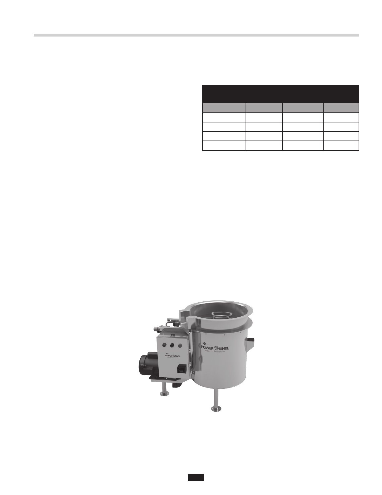
Product Overview
INTRODUCTION
The PowerRinse® Waste Collection System is a food
and food-related waste handling solution that improves
kitchen efficiency by increasing scrapping speed and
reducing bulk waste.
A series of nozzles along a trough aid in the pre-rinse
and scrapping of dishes. Water flow down the trough
moves waste into a scrap basket, which can then be
emptied into a waste or compost receptacle, while water
soluble waste is sent down the drain. The trough system
increases efficiency by allowing multiple users to scrap
and pre-soak dishes at the same time. The PowerRinse
Waste Collection System is an alternative to using a food
waste disposer or pulper system.
This Installation, Care, and Use Manual is for the Trough
(Model PRT) only (see Figure 1). For the Standard (Model
PRS) and Pot/Pan (Model PRP), please reference
separate document.
The PowerRinse Waste Collection System is CUL® US
Listed when installed in conjunction with InSinkErator
pumps and controls, and per the installation instructions
in this Installation, Care, and Use Manual (see Figures 3
and 4 for typical installations).
This Installation, Care, and Use Manual covers the models
listed in Table 1.
Table 1. Electrical Specifications
PowerRinse® Waste Collection System
Trough (Model PRT)
Model Part No. Voltage Phase
PRT-1 15441 110-120V 1
PRT-2 15441A 208/220-240V 1
PRT-3 15441B 208/220-240V 3
PRT-4 15441C 460-480V 3
IMPORTANT NOTE – These installation instructions
are for the benefit of the installing contractor.
InSinkErator and/or InSinkErator Factory Authorized
Service Centers do not make original installations. For
technical information not covered in these instructions,
contact the supplier, an InSinkErator Field Sales
Representative, or InSinkErator Foodservice Sales
and Service at 1-800-845-8345.
Figure 1. Trough (Model PRT)
3
Page 4
Product Overview
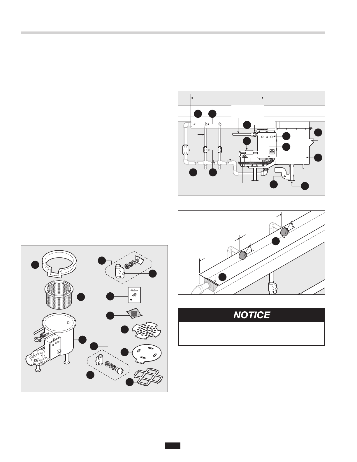
SYSTEM COMPONENTS
The PowerRinse® Waste Collection System includes the
following components (see Figure 2):
a. Trough Tray
b. Scrap Basket
c. Diffuser Assembly
d. Ball Valve
e. Waste Collector Base Assembly (see Figure 3)
f. Waste Collector Tank and Mounting Assembly
g. Control (Pre-wired)
h. Solenoid (Pre-wired)
i. Pump (Pre-wired)
j. Air Gap
k. Leveling Flange Feet
l. 2" Drain Discharge
m. 1/2" NPT Water Inlets (Hot and Cold Connections)
n. Installation, Care, and Use Manual
o. Mounting Hardware
• Lock Washers (12)
• 1/4"-20 Nuts (12)
p. Basket Cover
OPTIONAL COMPONENTS
q. Trough Nozzle Assembly
r. Ball Valve
s. Cover
t. Rack Guide
a
c
d
TYPICAL INSTALLATION
Figures 3 and 4 illustrate the typical installation of the
PowerRinse® Waste Collection System. For a
complete list of system components refer to the
System Components list located to the left of Figure 3.
See Figure 5 on next page for system dimensions.
10' (3 m)
Incoming Hot
q
c
3/4"
Piping
d
r
Figure 3. Typical Installation
3' (0.9 m)
Recommended
and Cold Water
Supply Lines
1-1/2"
Piping
Incoming Power
(1/2" Conduit)
c
m
i
3' (0.9 m)
Recommended
45°
g
h
l
k
45°
q
j
f
b
e
Figure 2. System Components
Installation, Care, and Use Manual
n
Trough (Model PRT)
WARNING indicates a hazardous situation which, if not avoided, could result in
death or serious injury.
CAUTION indicates a hazardous situation which, if not avoided, could result in
minor or moderate injury.
NOTICE is used to address practices not related to physical injury.
Please be certain that the person who installs or uses this appliance carefully reads
and understands the Safety Instructions contained in this manual.
Part No. 15443 Rev Awww.insinkerator.com/foodservice
Figure 4. Typical Diffuser and Trough Nozzle Installation
o
p
The PowerRinse® Waste Collection System pump
motor fan must have a minimum of 1" of clearance from
any wall or obstruction in order to operate correctly.
q
s
REQUIRED TOOLS / MATERIALS
The following items are needed to install the PowerRinse®
Waste Collection System:
r
t
o Screwdriver
o Pipe wrench
o 7/16" wrench or socket
o Tools and materials necessary to install the power line,
drain line, and the hot and cold water
The following items are needed if repositioning the control:
o 1/2" wrench or socket
4
Page 5
Product Overview
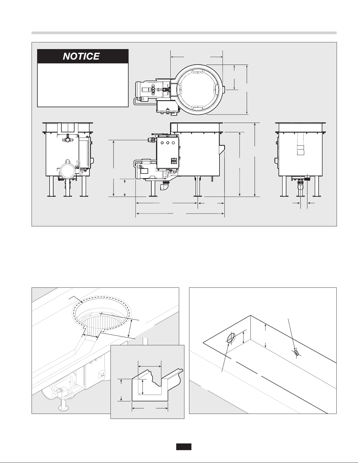
23.5" (597 mm)
The PowerRinse® Waste
Collection System pump motor
fan must have a minimum of 1"
of clearance from any wall or
obstruction in order to operate
co r rectly.
25. 41"-28. 41"
(64 5-722 mm )
7.93"-10.93"
(201-278 mm)
27. 96"
(710 m m)
Figure 5. PowerRinse® Waste Collection System Dimensions
40. 05"
(10 17 mm )
12.0 9"
(307 mm)
11. 25"
(286 mm)
(572 mm)
28.93"-31.93"
(735-811 mm)
22.5"
33"-3 6"
(8 38 -914 mm)
3"
(76 mm)
TABLE CUTOUT DIMENSIONS
Use the dimensions from Figure 6 for Trough
(Model PRT) table cutout. Weld the waste collector tray
to the underside of the table so the opening aligns with
the trough in the table.
Ø20"
(Ø507.5 mm)
6-1/2"
(165.1 mm)
Figure 6. Trough Table Cutout
(Model PRT)
Flange Detail Cross Section
5-1/2 "
(139.7 mm)
12-1/4"
(311.1 mm)
5- 3/4"
(14 6 .1 m m)
4"
(101. 6 mm)
8- 3/4"
(222.3 mm)
If using in line with a dishwasher, it is recommended to
mount the waste collector tray a minimum of 24" away
from the loading end of the dishwasher to allow enough
table space for a dish rack.
Optional Mounting Hole
for Trough Nozzle
Ø1-5/16" (Ø33.3 mm) Centered
3" min.
3" min.
(76.2 mm)
(76.2 mm)
1-1/4" min.
1-1/4" min.
(31.8 mm)
(31.8 mm)
Mounting Hole for Diffuser
Ø2" (Ø50.8 mm)
Centered Horizontally
Figure 7. Diffuser and Trough Nozzle Mounting Holes
5
Page 6
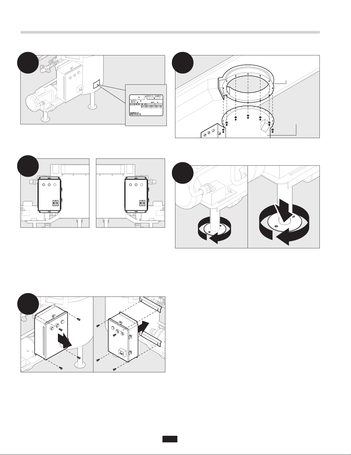
ASSEMBLY
Installation Instructions
1
Remove unit from package. Ensure that the power
supply is appropriate based on the control configuration
ordered with the unit. Verify using spec plate on tank.
2
3
Tro u gh
Tra y
Waste Collector
Base Assembly
Secure waste collector base assembly to trough tray
using provided lock washers and 1/4"-20 nuts.
4
Ensure that the control is on the proper side of the tank.
The control should always face the operator.
NOTE: The waste collector base assembly is shipped
with the control factory-installed on the left side of
the tank.
CHANGING THE CONTROL LOCATION
2a
Optional – to relocate the control, remove and save
four (4) bolts and nuts. Reposition box on other side of
tank and secure with previously removed hardware. It is
not necessary to disconnect factory-installed wiring.
Rotate legs clockwise when viewing from top until they
extend to the floor.
Optional – use the provided holes on the flanged foot
to secure unit to floor with anchors (not provided by
InSinkErator).
After relocating control, verify conduit and solenoid
connections are tight.
6
Page 7

Installation Instructions
ASSEMBLY (cont.)
INTERNAL PLUMBING INSTRUCTIONS
5
Ø2"
(50.8 mm)
2" NPT
Connection
Install diffuser at end of trough.
5a
Ø1-5/16"
(Ø33.3 mm)
45°
3/4" NPT
Connection
PLUMBING
PROPERTY DAMAGE
• Installation must comply with all local plumbing
codes.
• If water pressure exceeds the recommended
80 psi, pressure regulators should be used.
WATER CONNECTIONS
Plumb a hot and a cold water supply line to mixer valve
(see Figure 8). Connections are 1/2" NPT.
IMPORTANT NOTES:
• Mixing valve can be relocated.
• Hot and cold water lines must match the markings on
mixer valve. If lines are reversed, mixer valve will not
operate properly after adjustment.
• It is recommended that ball type shutoff valves be
installed in line with the cold and hot water lines.
• A minimum of 30 psi at the mixer valve is needed for
the waste collector to operate correctly.
Optional – Install trough nozzle(s) at a 45 degree angle
as shown.
6
Diffuser
1-1/2"
Ball
Valve
Trough Nozzle
3/4"
Ball
Valve
3/4"
Piping
Reducing
Tee
1-1/2"
Piping
Plumb 1-1/2" pipe from pump outlet to diffuser opening
(re-circulated pipe). A ball valve should be installed near
diffuser to regulate water ow.
Cold Water
Supply Line
Mixer
Valve
Figure 8. Water Connections
Hot
Water
Supply
Line
IMPORTANT NOTE: This air gap meets ASME
A112.1.2-2012 standard and eliminates the need for a
vacuum breaker installed with the system (see Figure 9).
Air Gap
NOTE: If installing trough nozzles, use reducing tees
to plumb 3/4" pipe from the 1-1/2" re-circulated pipe to
nozzle(s). A ball valve should be installed near
each nozzle(s).
Figure 9. Air Gap
7
Page 8

Installation Instructions
PLUMBING (cont.)
ADJUSTING WATER TEMPERATURE
NOTE: It may be necessary to adjust the mixing valve to
set the appropriate water temperature.
To adjust water temperature (see Figure 10):
1. Unscrew button head screw on the valve cap until cap
can be pulled out.
2. Pull cap out.
3. Turn cap to adjust water temperature.
4. When desired temperature is reached, push cap in
and tighten button head screw to secure cap.
2
Cap
1
Figure 10. Adjusting Water Temperature
Button
Head
Screw
3
3
Cap
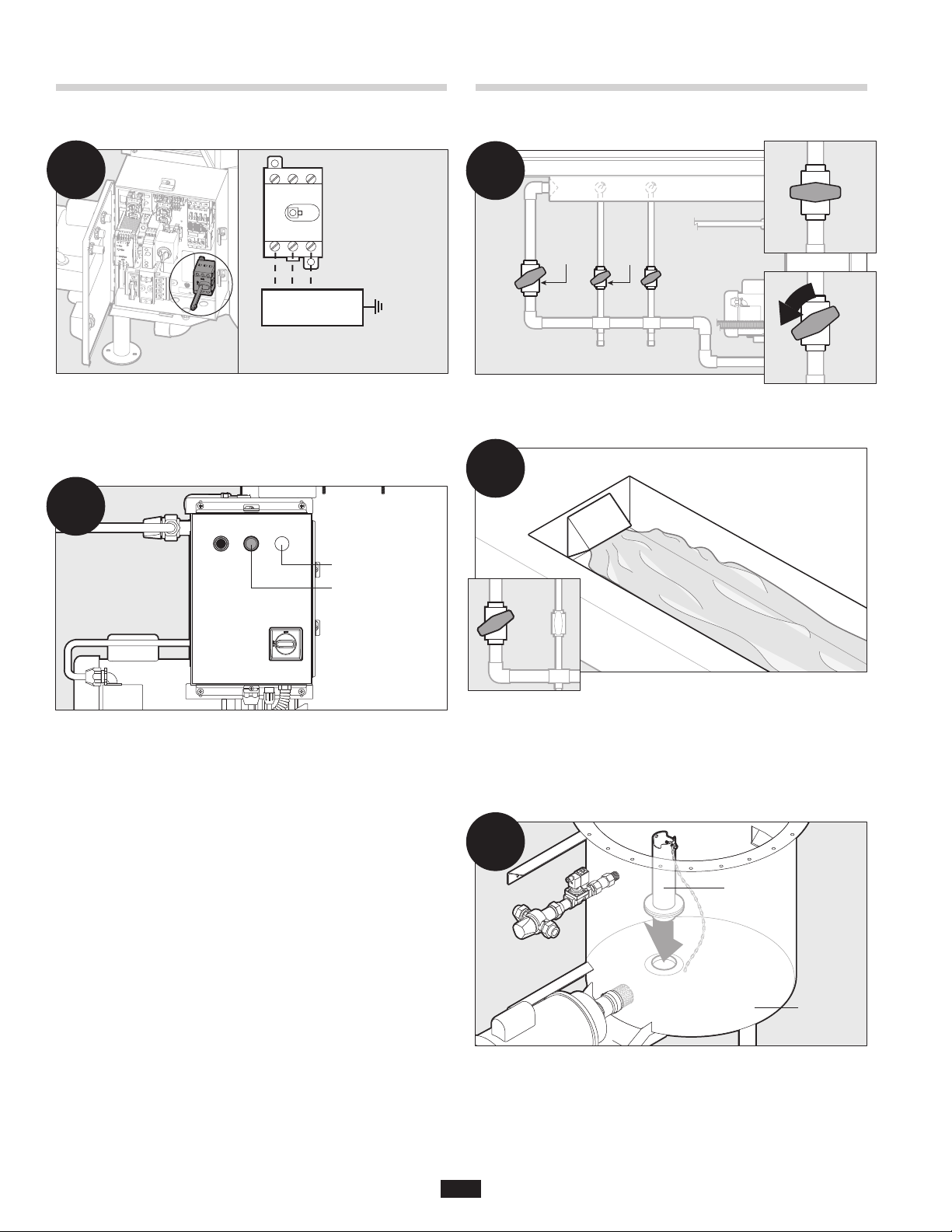
ELECTRICAL
ELECTRICAL SHOCK
• Turn off all electrical supply to the collector before
attempting any work on it. Use a voltmeter or
circuit tester to ensure that power is off.
• Installation must conform to local electrical codes.
• All control centers and collector components must
be carefully and permanently grounded.
• A properly fused disconnect must be installed at
the electrical supply source for the control center.
ELECTRICAL DISCONNECT SWITCH
The switch on the front panel of the control disconnects
the line voltage (see Figure 12). It interlocks with the
front cover so that the panel cannot be opened unless
the switch is in the OFF position.
ON
OFF
Position
Position
Electrical
Disconnect
Switch
DRAIN PIPING
Plumb a 2" drain line through a “P-trap” from the 2" male
threaded nipple on the bottom of the waste collector
tank (see Figure 11).
2" Drain
Connection
Waste
Collector
Tan k
Figure 11. Drain Piping
Ensure all connections are tight and leak free,
including rubber boots and plumbing connections
supplied by the manufacturer, before moving forward
and engaging the system.
Figure 12. Electrical Disconnect Switch
NOTE: Use of the electrical disconnect switch results
in a 30 second delay before system can be restarted.
You must wait 30 seconds after reactivation of the line
disconnect switch before system will start.
PROPERTY DAMAGE
• Ensure that the control center voltage and phase
match the pump and electrical supply. Reference
the nameplates for voltage and phase.
• The pump motor wiring diagram is shown on the
casing of the pump.
PERSONAL INJURY
Disconnect electricity at line disconnect switch
before servicing system.
8
Page 9

Installation Instructions
1
2
ELECTRICAL (cont.)
ELECTRICAL CONNECTIONS
NOTE: Ensure that the power supply is appropriate
based on the control configuration ordered with the unit.
One electrical connection is required. To connect the
waste collection system to the electricity:
1
2
Remove top cover retainers by loosening screws and
open the front panel.
NOTE: Electrical disconnect switch must be in OFF
position to open control panel (see Figure 12).
Control
2
INITIAL SETUP AND VERIFICATION
PREPARE THE SYSTEM
1
ON
Position
Electrical
Disconnect
Switch
Turn electrical disconnect switch to the ON position.
Open shutoff valves in water lines, if installed.
2
Start
Indicator Light
Solenoid
(Pre-wired)
Incoming
Power
(1/2" Conduit)
1/2" Knockout
Run power from main power supply to the 1/2" knockout
on bottom of control and connect as shown.
NOTE: Be sure to use liquid tight conduit and conduit
fittings.
Pump
(Pre-wired)
3
1
Press the START button. Indicator light turns on.
NOTE: If the unit does not turn on, see Troubleshooting.
3
Verify that the pump is functioning correctly.
IMPORTANT NOTE: Wait time until pump
engages is approximately 60 seconds after
starting unit.
Close front panel and tighten screws on top cover
retainers to secure.
9
Page 10
Installation Instructions Operating Instructions
INITIAL SETUP AND VERIFICATION (cont.)
3a
For 3 Phase units only – Ensure pump motor fan is
rotating clockwise (when viewed from the motor end).
If rotation is counter-clockwise, turn off power supply,
open front panel, and switch L1 and L2 connections.
1 ON
0 OFF
L1 L2 L3*
Incoming Power
Supply
*NOTE: Single Phase models
do not have L3 wire.
Panel
Ground
Plug
4
Indicator Light
Stop
MAIN OPERATION
1
1-1/2"
Ball
Valve
Check ball valve(s) settings to ensure they are not
completely shut or fully open.
3/4"
Ball
Valve
2
Closed
Slightly
Open
Turn off unit by pressing the STOP button. Indicator
light turns off.
NOTE: If the unit does not turn off, see Troubleshooting.
Ball
Valve
Adjust ball valve for diffuser until desired water flow rate
in trough is achieved.
Optional – If trough nozzles are installed, adjust ball
valve(s) until water plume hits desired location in
the trough.
3
Overflow
Tub e
Waste
Collector
Tan k
Place the overflow tube into the drain at the bottom of
waste collector tank.
10
Page 11

MAIN OPERATION (cont.)
Operating Instructions
4
Scrap
Basket
Waste
Collector
Tan k
Place scrap basket inside waste collector tank. Unit
must always have the scrap basket in place during
operation.
4a
Cover
Waste
Collector
Tan k
Rack
Guide
Waste
Collector
Tan k
5
Start Indicator Light
To begin, press START button on control and allow the
reservoir tank to fill with water. Indicator light turns on.
Pump turns on and water plume starts once tank has
reached optimal fill level (approximately 60 seconds
after pushing the START button).
6
move solid waste from the surface.
Pre-soak problem dishes with baked-on or difficult to
remove food by setting them in the trough or under the
plume(s). Solid waste is collected in the scrap basket.
Scrap soiled dishes using the water in the
trough and from the nozzle plume(s) to help
Optional – Place cover or rack guide on trough tray.
Use of cover/rack guide is optional but recommended
to maximize workspace.
DO NOT use corrosive chemicals for scrapping.
7
Indicator Light
Stop
Press STOP on the control panel. Indicator light turns off.
11
Page 12

Operating Instructions
1
1
MAIN OPERATION (cont.)
TIMED RUN FEATURE
The PowerRinse® Waste Collection System has a builtin shut off timer in the control. The timer is preset for 20
minutes from factory. After the set time elapses, the unit
will shut off.
To adjust timer:
1
Timer
Switch
To turn timed run ON or OFF:
1
2
Timer ON and
OFF Switch
Open the control panel. Locate the Timer ON and OFF
switch.
2
Timer ON
Position
Timer OFF
Position
2
Open the control panel. Locate the Timer Switch.
2
Timer
Switch
Time
Range
Switch
Main Dial
Rotate time range switch or main dial to desired
settings (as shown). The time range switch sets the
increments (0.1s, 1s, 10s, etc.) and the main dial is the
“multiplier.” The factory default is 10m on time range
switch and 2 on the main dial, or 20 minutes.
Move switch to desired position.
12
Page 13

Operating Instructions
TO EMPTY SCRAP BASKET
1
Indicator Light
Stop
Ensure unit is turned off by pressing the STOP button
on the control.
1a
Cover
Rack
Guide
TO CLEAN UNIT
It is recommended that unit be cleaned daily at end of
shift, and as needed throughout the day.
1
Overflow
Tub e
Waste
Collector
Tan k
Turn off unit and empty scrap basket (see above
instructions). Pull overflow tube to drain water inside
waste collector tank.
2
Waste
Collector
Tan k
Remove cover or rack guide, if in use.
Waste
Collector
Tan k
2
Scrap
Basket
Waste
Collector
Tan k
Remove scrap basket and dump waste into appropriate
trash or compost receptacle.
Waste
Collector
Tan k
Pump
Inlet
Screen
Remove pump inlet screen.
3
DO NOT use corrosive chemicals for scrapping.
Rinse cover or rack guide, scrap basket, tray,
pump inlet screeen, and tank interior. Scrap
basket may be run through dishwasher.
13
Page 14

Troubleshooting
ELECTRICAL SHOCK
• Turn off all electrical supply to the collector
before attempting to work on it. Use a voltmeter
or circuit tester to ensure that the power is off.
• DO NOT bypass interlock switch.
Troubleshooting for problems other than what is listed below should be performed by a qualified service person.
Troubleshooting performed by untrained personnel could result in electrical shock or damage to the PowerRinse®
waste collection system.
SYSTEM TROUBLESHOOTING
PROBLEM POSSIBLE CAUSE SOLUTION
Waste Collector does not turn on. • Electrical supply turned off.
• Fuse blown or circuit breaker turned
off at power supply.
• Control circuit fuse blown.
• Line disconnect switch on control not
in the “ON” position.
• Line disconnect switch on control is
defective.
• Start switch on control center is
defective.
• Stop switch on control center is
defective.
• Turn on the electrical supply.
• Replace fuse or reset circuit breaker.
• Replace fuse.
• Turn to “ON” position, wait 30 seconds
before attempting to start again.
• Call for service.
• Call for service.
• Call for service.
Waste Collector will start when
“START” button is pushed, but
shuts down when “START” button
is released.
Waste Collector stops
unexpectedly.
Waste Collector turns on, but pump
does not operate correctly.
• Insufficient time allowed after line
disconnect switch on control center
is turned to the “ON” position.
• 24V power from control center
(control circuit) is low or not present.
• Fuse blown or circuit breaker tripped
at power source.
• 24V power from control center
(control circuit) is low or not present.
• STOP button on control has been
pushed.
• Line disconnect switch has been
turned to the “OFF” position.
• Pump clogged.
• Pump inlet screen clogged.
• Allow 30 seconds before attempting system
startup (at “START” switch).
• Call for service.
• Replace fuse or reset circuit breaker.
• Call for service.
• Push “START” button on control center.
• Turn to “ON” position, wait 30 seconds
before attempting to start system.
NOTE: Line disconnect switch is only
intended for use in the event of control
center servicing.
• Call for service.
• Call for service.
• Clean unit.
14
Page 15

PROBLEM POSSIBLE CAUSE SOLUTION
Water flows continuously before
control is turned on.
Troubleshooting
• Solenoid valve is stuck open.
• Solenoid valve is defective.
• Call for service.
• Replace solenoid valve.
Drain is clogged. • Scrap basket not in place when using
Waste Collector.
• Water is too cold.
Water does not fill in tank. • Overflow pipe not in drain. • Place overflow pipe in drain.
Water system is too hot or cold. • Mixing valve not adjusted properly. • Adjust mixing valve to achieve proper water
Pump leaks water. • Pump has failed. • Replace pump.
Waste Collector not circulating any
water or not enough water.
Unit does not stop. • Control has failed. • Stop unit by turning the electrical
Drain consistently clogs. • Consultation required to
• Ball valve(s) closed. • Adjust ball valve – open more.
troubleshoot.
• Call plumber.
NOTE: Scrap basket should be in place at
all times during operation.
• Adjust mixer valve.
temperature.
disconnect switch to the OFF position.
Call for service.
• Call plumber.
Pump inlet screen clogged. • Scrap basket not in place when
using Waste Collector.
• Turn off unit, remove basket and
clean debris from screen with hand
or overhead sprayer.
15
Page 16

Model PRT-1 (110-120V, 1 Phase) Wiring Diagram
ELECTRICAL SHOCK
• Turn off all electrical supply to the collector before
attempting any work on it. Use a voltmeter or
circuit tester to ensure that power is off.
• Installation must conform to local electrical codes.
• All control centers and collector components must
be carefully and permanently grounded.
• A properly fused disconnect must be installed at
the electrical supply source for the control center.
120 V
110 -12 0 V
1-phase
1 Phase
1/2 to 2 HP
PROPERTY DAMAGE
• Ensure that the control center voltage and phase
match the pump and electrical supply. Reference
the nameplates for voltage and phase.
• The pump motor wiring diagram is shown on the
casing of the pump.
Note: Black wires = Line voltage (110 - 120 V).
Call Toll Free 1-800-845-8345
for the nearest InSinkErator
Authorized Service Agency or
to reach Technical Support.
16
Page 17

Model PRT-2 (208/220-240V, 1 Phase) Wiring Diagram
ELECTRICAL SHOCK
• Turn off all electrical supply to the collector before
attempting any work on it. Use a voltmeter or
circuit tester to ensure that power is off.
• Installation must conform to local electrical codes.
• All control centers and collector components must
be carefully and permanently grounded.
• A properly fused disconnect must be installed at
the electrical supply source for the control center.
120 V
208/220-240V
1-phase
1 Phase
1/2 to 2 HP
PROPERTY DAMAGE
• Ensure that the control center voltage and phase
match the pump and electrical supply. Reference
the nameplates for voltage and phase.
• The pump motor wiring diagram is shown on the
casing of the pump.
Note: Black wires = Line voltage (208/220 - 240 V).
Call Toll Free 1-800-845-8345
for the nearest InSinkErator
Authorized Service Agency or
to reach Technical Support.
17
Page 18

Model PRT-3 (208/220-240V, 3 Phase) Wiring Diagram
ELECTRICAL SHOCK
• Turn off all electrical supply to the collector before
attempting any work on it. Use a voltmeter or
circuit tester to ensure that power is off.
• Installation must conform to local electrical codes.
• All control centers and collector components must
be carefully and permanently grounded.
• A properly fused disconnect must be installed at
the electrical supply source for the control center.
120 V
208/220-240V
1-phase
3 Phase
1/2 to 2 HP
PROPERTY DAMAGE
• Ensure that the control center voltage and phase
match the pump and electrical supply. Reference
the nameplates for voltage and phase.
• The pump motor wiring diagram is shown on the
casing of the pump.
Note: Black wires = Line voltage (208/220 - 240 V).
Call Toll Free 1-800-845-8345
for the nearest InSinkErator
Authorized Service Agency or
to reach Technical Support.
Overload Settings
Model Current Reset
PRT-3 3.2 Automatic
18
Page 19

Model PRT-4 (460-480V, 3 Phase) Wiring Diagram
ELECTRICAL SHOCK
• Turn off all electrical supply to the collector before
attempting any work on it. Use a voltmeter or
circuit tester to ensure that power is off.
• Installation must conform to local electrical codes.
• All control centers and collector components must
be carefully and permanently grounded.
• A properly fused disconnect must be installed at
the electrical supply source for the control center.
120 V
460-480V
1-phase
3 Phase
1/2 to 2 HP
PROPERTY DAMAGE
• Ensure that the control center voltage and phase
match the pump and electrical supply. Reference
the nameplates for voltage and phase.
• The pump motor wiring diagram is shown on the
casing of the pump.
Note: • Black wires = Line voltage (460 - 480 V).
Call Toll Free 1-800-845-8345
for the nearest InSinkErator
Authorized Service Agency or
to reach Technical Support.
Overload Settings
Model Current Reset
PRT-4 1.5 Automatic
19
Page 20

Limited Warranty
InSinkErator®, a division of Emerson Electric Co., (“InSinkErator”
or “Manufacturer” or “we” or “our” or “us”) warrants to the original
purchaser only (“Customer” or “you” or “your”), subject to the
exclusions below, that your InSinkErator® PowerRinse® Waste
Collection System (the “InSinkErator Product”) will be free from
defects in material and workmanship for one year from the original
date of purchase (the “Warranty Period”). This limited warranty
terminates if the original purchaser transfers the InSinkErator Product
to any other person or entity.
If a covered claim is made during the Warranty Period, Manufacturer
will, through its authorized service representative, and at
Manufacturer’s or its authorized service representative’s sole
discretion, either repair or replace your InSinkErator Product. If your
InSinkErator Product is replaced, the warranty on the replacement
InSinkErator Product will be limited to the unexpired term remaining
in the original Warranty Period. YOUR SOLE AND EXCLUSIVE
REMEDY UNDER THIS LIMITED WARRANTY SHALL BE LIMITED
TO REPAIR OR REPLACEMENT OF THE INSINKERATOR
PRODU CT.
What is Covered
This limited warranty includes repair or replacement of your
InSinkErator Product, accessories if included in the original
InSinkErator Product package, and all replacement parts and
labor costs if provided by an authorized InSinkErator service
representative.
What is not Covered
This limited warranty does not extend to and expressly excludes:
• Losses or damages or the inability to operate your InSinkErator
Product resulting from conditions beyond the Manufacturer’s
control including, without limitation, accident, alteration, misuse,
abuse, neglect, or negligence (other than Manufacturer’s).
• Wear and tear expected to occur during the normal course of use,
including without limitation, cosmetic rust, scratches, dents or
comparable and reasonably expected losses or damages.
• Failure to install, maintain, assemble, or mount the InSinkErator
Product in accordance with Manufacturer’s instructions or local
electrical and plumbing codes, faulty or improper electrical
installation, faulty or improper plumbing installation, clogged drain
lines, or an improperly sized unit (as specified by InSinkErator).
What we will do to Correct Problems
To file a warranty claim during the Warranty Period, you may call Toll
Free 1-800-845-8345 for the nearest InSinkErator Authorized Service
Agency or to reach Technical Support, or you may visit our website at
www.insinkerator.com.
The following information must be provided as part of your warranty
claim: your name, address, phone number, your InSinkErator Product
model and serial number. You will be required to submit supporting
documentation of the date of purchase.
Manufacturer or its authorized service representative will determine,
in its sole and absolute discretion, if your InSinkErator Product is
covered under this limited warranty. Only an authorized InSinkErator
service representative may provide warranty service. InSinkErator
is not responsible for warranty claims arising from work performed
on your InSinkErator Product by anyone other than an authorized
InSinkErator service representative.
InSinkErator® may make improvements and changes in the specification at any time, in its sole discretion, without notice or obligation and further
reserves the right to change or discontinue models. ©2016 InSinkErator®, a business unit of Emerson Electric Co. All rights reserved.
No Other Express Warranty Applies
THE LIMITED WARRANTIES PROVIDED ABOVE ARE THE SOLE
AND EXCLUSIVE WARRANTIES PROVIDED BY MANUFACTURER
TO THE ORIGINAL PURCHASER, AND ARE IN LIEU OF ALL
OTHER WARRANTIES, WRITTEN OR ORAL, EXPRESS OR
IMPLIED, WHETHER ARISING BY OPERATION OF LAW OR
OTHERWISE, INCLUDING, WITHOUT LIMITATION, WARRANTIES
OF MERCHANTABILITY OR FITNESS FOR A PARTICULAR
PURPOSE, WHETHER OR NOT THE PURPOSE HAS BEEN
DISCLOSED AND WHETHER OR NOT THE INSINKERATOR
PRODUCT HAS BEEN SPECIFICALLY DESIGNED OR
MANUFACTURED FOR YOUR USE OR PURPOSE .
Limitation of Liability
TO THE EXTENT PERMITTED BY LAW, IN NO EVENT
SHALL MANUFACTURER OR ITS AUTHORIZED SERVICE
REPRESENTATIVES BE LIABLE FOR ANY INCIDENTAL, SPECIAL,
INDIRECT, OR CONSEQUENTIAL DAMAGES, INCLUDING
ANY ECONOMIC LOSS, WHETHER RESULTING FROM
NONPERFORMANCE, USE, MISUSE OR INABILITY TO USE THE
INSINKERATOR PRODUCT OR THE MANUFACTURER’S OR ITS
AUTHORIZED SERVICE REPRESENTATIVE’S NEGLIGENCE.
MANUFACTURER SHALL NOT BE LIABLE FOR DAMAGES
CAUSED BY DELAY IN PERFORMANCE AND IN NO EVENT,
REGARDLESS OF THE FORM OF THE CL AIM OR CAUSE OF
ACTION (WHETHER BASED IN CONTRACT, INFRINGEMENT,
NEGLIGENCE , STRICT LIABILITY, OTHER TORT OR
OTHERWISE), SHALL MANUFACTURER'S LIABILIT Y TO YOU
EXCEED THE PRICE PAID BY THE ORIGINAL OWNER FOR THE
INSINKERATOR
The term "consequential damages" shall include, but not be limited
to, loss of anticipated profits, business interruption, loss of use or
revenue, cost of capital or loss or damage to property or equipment.
Some states do not allow the exclusion or limitation of incidental or
consequential damages, so the above limitation may not apply to you.
This warranty gives you specific legal rights and you may also have
other rights which vary from state to state.
PRODU CT.
 Loading...