

Page 1
IN
SINK
ERATOR
Commercial
Products Group
COMMERCIAL DISPOSER
CONTROL CENTER
Installation Manual
Model MSLV
WARNING
CAUTION
Please be certain that the person who installs or uses this appliance carefully reads and understands the Safety Instructions
contained in this manual.
The Warning signal alerts you to potential hazards or unsafe practices which, if not avoided, could
result in severe personal injury or death.
The Caution signal alerts you to hazards or unsafe practices which, if not avoided, may result in
minor personal injury or property damage.
Part No. 14187 - March, 1999
Page 2

TABLE OF CONTENTS
INTRODUCTION 2
FEATURES 2
MOUNTING THE CONTROL CENTER 2
PLUMBING CONNECTIONS 3
ELECTRICAL CONNECTIONS 4
TIME DELAY RELAY 5
OPERATING INSTRUCTIONS 6
TROUBLESHOOTING 6
SCHEMATIC WIRING DIAGRAMS 7-10
1
Page 3
FEATURES/MOUNTING THE CONTROL CENTER
INTRODUCTION
The MSLV Control Center is UL* listed for use with ISE
Commercial Food Waste Disposers. See Table 1 for approved
combinations. The control center operates the disposer. Its main
functions are:
• To start and stop the disposer.
• To start the water flow to the disposer.
TABLE 1. Approved Disposer and Control Center Combinations
Model Waste Disposer Model
PUSH BUTTON OPERATION
Push black button to start disposer. Push
red button to stop disposer.
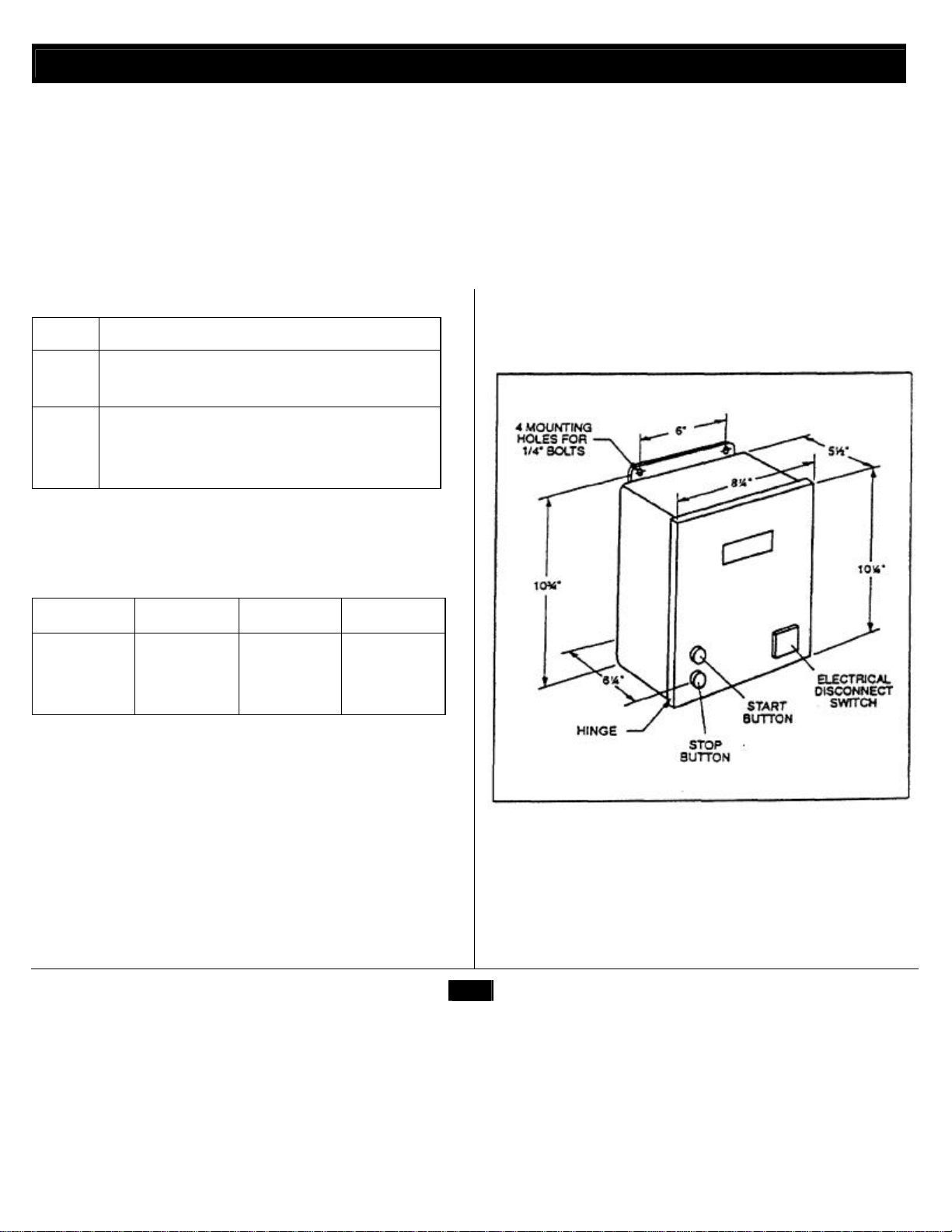
MOUNTING THE CONTROL CENTER
Using flanges at the back of the control center enclosure and only
mount panel in the upright vertical position (door hinge is on the
left). See Figure 1.
Locate control center within sight of disposer per local codes.
If box is mounted to the sink table, recess the box so that the
buttons do not extend beyond the table's edge.
MSLV-1
MSLV-2
MSLV-3
MSLV-4
SS50-26, SS75-27. SS100-28, SS125-25, SS150-34.
SS150-38, SS200-27, SS200-31
SS50-27, SS75-28, SS100-29, SS125-26, SS150-36,
SS150-39. SS200-29. SS200-32 SS300-25, SS300-27.
SS500-28. SS500-30. SS750-13, SS750-15, SS1000-10,
SS1000-12
Control center models and specifications are shown in Table 2
TABLE 2. Electrical Specifications
Model Voltage Phase hp
MSLV-1 120V 1 Ø 1/2-2
MSLV-2 208-240 V 1 Ø 1/2-2
MSLV-3 208-240 V 3 Ø
MSLV-4 380-460 V 3 Ø 1/2-10
1/2
-10
FEATURES
LOW VOLTAGE CONTROL
Controls operate on a 24 V solid state control circuit.
FIGURE 1. Control Center Dimensions
ENCLOSURE
Stainless steel NEMA 4 construction.
ELECTRICAL DISCONNECT SWITCH
The lever switch on the front panel of the control center
connects line voltage. It interlocks with the front cover so that the
cover cannot be opened unless the switch is in OFF position.
2
Page 4
PLUMBING CONNECTIONS
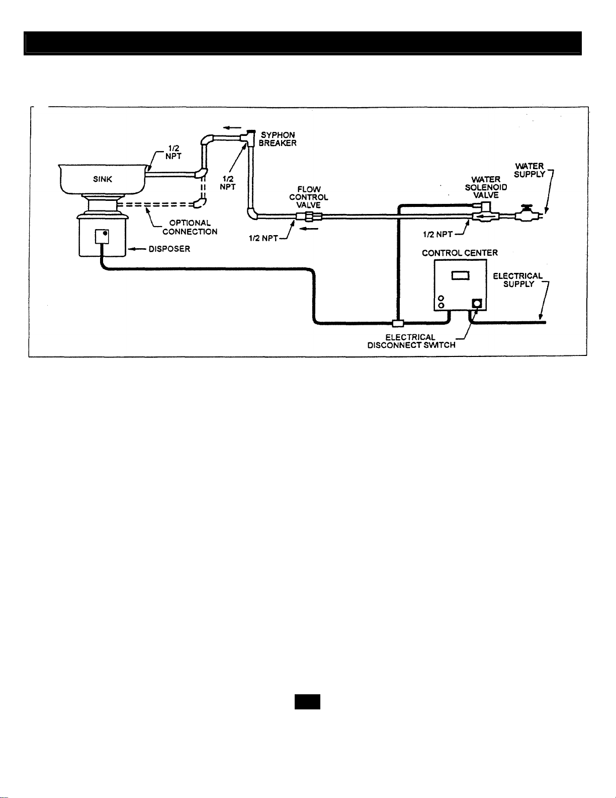
FIGURE 2. Typical Installation Diagram
PLUMBING CONNECTIONS
The solenoid valve is packed with the control center. The flow
control valve and syphon breaker are supplied with all complete
disposer packages (packed separately).
The solenoid valve is supplied with a 24 V coil. Make certain that the
valves are plumbed according to water flow direction arrows marked
on valves or the valves will not function properly.
The flow control valve regulates all water flowing into the disposer.
This conserves water and prevents overloading. Check direction of
water flow arrows.
A syphon breaker must be installed above the sink flood plane per
local plumbing codes. Check direction of water flow arrows.
3
Page 5

ELECTRICAL CONNECTIONS
electrical codes.
• Turn off the electrical supply to the disposer before attempting
any work on it. Use a voltmeter or circuit tester to ensure that
the power is off.
• Alt installation work must conform to local plumbing and
• All control centers and disposers must be carefully and
permanently grounded.
• A properly fused disconnect must be installed at the electrical
supply source for the control center.
NOTE: The MSLV control center has a door disconnect switch,
the disconnect switch must be in the off position before the panel
door can be opened. Power is still present at the disconnect until
power is turned off at the electrical supply source.
WARNING
ELECTRICAL SHOCK PROPERTY DAMAGE
ELECTRICAL CONNECTIONS
The MSLV control center uses low voltage (24 V) to operate contactor
coils, push buttons and solenoid valves. Red wires denote 24 V circuit.
Connect the incoming line power to the electrical door disconnectswitch and connect the disposer motor to labeled terminal blocks
in the control center. Use appropriate schematic wiring diagram,
Figures 7, 8, 9 or 10. A wiring diagram is also located on the
inside door of the control center. Wire the disposer motor for
correct voltage using the connection diagram inside the motor
terminal box.
Connect water solenoid valve as shown in Figure 3.
• Ensure that control center voltage and phase match the
disposer motor and electrical supply. Check name plates on
disposer and control centers for voltage and phase
specifications.
• Refer to the control center wiring diagrams in this manual for
correct connection.
• Use NEMA 4 watertight electrical connectors (not supplied)
when making electrical connections to the control center.
WATER SOLENOID VALVE
Connect solenoid valve to the low voltage solenoid terminals
numbers 4 and 5.
FIGURE 3. Solenoid valve connections to control panel
terminals
CAUTION
Wire per local electrical code using 7/8" diameter holes in bottom
of control center cabinet and install NEMA 4 watertight electrical
connectors. (Not supplied).
After completing the connections, close door and fasten all locking
clamps. Replace disposer motor cover. Turn on power.
4
Page 6

TIME DELAY RELAY
The time delay relay may be used with the MSLV to delay solenoid valve
shut-off, providing a post flush. This helps prevent drain line stoppages
and is beneficial when ground food waste must travel through many
bends or a long horizontal run, in the drain line. It is adjustable from 0 to
10 minutes and factory set to provide approximately a 5 minute delay. To
adjust the time. SHUT OFF ELECTRIC POWER. Inside unit, locate the
adjustment knob. Turn clockwise to increase delay. Turn
counterclockwise to decrease delay. See Figure 4 for wiring.
Ensure the voltage rating on the time delay relay and solenoid valve are
24 volts.
TIME DELAY RELAY
FIGURE 4. Time delay relay connections
5
Page 7

OPERATING INSTRUCTIONS/ TROUBLE SHOOTING
•
Allow only trained personnel to operate disp
oser.
•
Do not put fingers or hands into the disposer.
be in the direction of the arrow on valve.
TO STOP
1. No incoming line power. Tur
n line power on.
Please read the disposer operating instructions and train personnel before
operating the disposer. The operating instructions are supplied with the
disposer and Include:
< Disposer operation.
< How to restart the disposer after a jam condition.
ELECTRICAL SHOCK/PROPERTY DAMAGE
• Troubleshooting other than what is recommended in this section
should only be performed by qualified service personnel.
WARNING
• Use baffles and guarding to avoid splashing and ejection of
materials.
• When attempting to remove objects from a disposer, use longhandled tongs or pliers.
• Turn power off before clearing a jam, removing an object from the
disposer or pressing the red reset button (see
Troubleshooting this page).
• Disconnect electricity before adjusting set points.
OPERATING INSTRUCTIONS D. Water flows constantly before start button is pushed.
TO START
neck to ensure disposer is free of foreign objects. 2 sure power is on.
3. Push start button. Disposer motor will run and water will flow into
the disposer.
Push stop button. Disposer motor and water will stop. (If time delay
relay is used the water flow will stop in 1-10 minutes).
TROUBLESHOOTING
This control center was inspected and tested under operating conditions
before shipment from the factory. In case of trouble, check the items
listed below.
A. Disposer motor will not start and water does not flow.
2. Electrical disconnect switch is not on. Turn electrical disconnect
switch to ON position.
3. Control circuit Fuse FNA2 is blown. Replace fuse.
B. Disposer motor stops while grinding but water continues to flow.
WARNING
PERSONAL INJURY
• Further troubleshooting performed by untrained personnel could
result in electric shock or damage to the control center.
• All electrical checks must be performed by a qualified professional.
C. Disposer will not start but water flows.
1. Overload protector on the disposer may have tripped. Press stop
button. Locate red reset button. on front of disposer electrical
cover. Press to reset. If motor had been running, wait five
minutes for the motor and overload to cool down.
2. Disposer is jammed. Press stop button and follow directions for
unjamming supplied with disposer.
1. Water solenoid valve is installed backward. Water flow should
2. Water solenoid valve is wired incorrectly. Check schemtic
wiring diagram, figures 5, 6, 7 and 8.
E. Overload trips frequently.
Do not overload disposer with excess amounts of garbage and
water.
If trouble still persists, call your nearest ISE Authorized Service
Agency. For the location of your nearest service agency, call toll-free 1-
1.
Disposer is jammed. Press stop button and follow directions for
unjamming supplied with the disposer.
2. Disposer motor overload protector has tripped. Follow
instruction in C1.
6
Page 8

Schematic Wiring Diagram - Model MSLV 1 Ø 1/2-2 hp
PROPERTY DAMAGE
WARNING
CAUTION
ELECTRICAL SHOCK
• Turn off all electrical supply to the disposer before attempting any work on
it. Use a voltmeter or circuit tester to ensure that power is off.
• Installation must conform to local electrical codes.
•
All control centers and disposers must be carefully and permanently
grounded.
• A properly fused disconnect must be installed at the electrical supply source
for the control center.
• Ensure that the control center voltage and phase match the disposer motor
and electrical supply. Check name-plates on disposers and control centers for
voltage and phase specification.
• The disposer motor wiring connection is shown in the disposer terminal box.
• Red wires - Low voltage (24v)
Note:
control
• Black wires - Line voltage (380460v) control
7
Page 9

Schematic Wiring Diagram - Model MSLV 208-240v 1 Ø 1/2 - 2 hp
8
WARNING
ELECTRICAL SHOCK PROPERTY DAMAGE
• Turn off all electrical supply to the disposer before attempting any
work on it. Use a voltmeter or circuit tester to ensure that power is off.
• Installation must conform to local electrical codes.
• All control centers and disposers must be carefully and permanently
grounded.
• A properly fused disconnect must be installed at the electrical supply
source for the control center.
• Ensure that the control center voltage and phase match the
disposer motor and electrical supply. Check name-plates on
disposers and control centers for voltage and phase specification.
• The disposer motor wiring connection is shown in the disposer
terminal box.
CAUTION
Note: • Red wires • Low voltage (24v)
control
• Black wires - Line voltage
(380-460V) control
Page 10

Schematic Wiring Diagram - Model MSLV 208-240v 3 Ø 1/2 - 10 hp
WARNING
ELECTRICAL SHOCK PROPERTY DAMAGE
• Turn off all electrical supply to the disposer before attempting any work
on it. Use a voltmeter or circuit tester to ensure that power is off.
• Ensure that the control center voltage and phase match the disposer
motor and electrical supply. Check name-plates on disposers and
control centers for voltage and phase specification.
CAUTION
• Installation must conform to local electrical codes.
• All control centers and disposers must be carefully and permanently
grounded.
• A properly fused disconnect must be installed at the electrical supply
source for the control center.
• The disposer motor wiring connection is shown in the disposer
terminal box.
Note:
•
Red wires - Low voltage (24v)
control
• Black wires - Line voltage
(380-460v) control
9
Page 11

Schematic Wiring Diagram - Model MSLV 380-460v 3 Ø 1/2 - 10 hp
• Installation must conform to local elec
trical codes.
WARNING
ELECTRICAL SHOCK PROPERTY DAMAGE
• Turn off all electrical supply to the disposer before attempting any
work on it. Use a voltmeter or circuit tester to ensure that power is off.
• Ensure that the control center voltage and phase match the
disposer motor and electrical supply. Check name-plates on
disposers and control centers for voltage and phase specification.
CAUTION
• All control centers and disposers must be carefully and permanently
grounded.
• A properly fused disconnect must be installed at the electrical supply
source for the control center.
• The disposer motor wiring connection is shown in the disposer
terminal box.
• Red wires - Low voltage (24v)
Note:
control
• Black wires - Line voltage
(380-460v) control
10
 Loading...