

Page 1
DISPOSER CONTROL CENTER
Installation Manual
Model MSLV
www.insinkerator.com
The Danger signal indicates an immediately hazardous situation which, if not
avoided, will result in death or serious injury.
The Warning signal alerts you to potential hazards or unsafe practices which, if
not avoided, could result in severe personal injury or death.
The Caution signal alerts you to hazards of unsafe practices which, if not avoided,
may result in minor personal injury or property damage.
Please be certain that the person who installs or uses this appliance carefully reads
and understands the Safety Instructions contained in this manual
Part No. 14187 - April 2006
Page 2
I ON
0 OFF
START
STOP
10-3/4"
11-1/2"
10-1/4"
6"
8-1/4"
5-9/16"
7"
START
BUTT
ON
ELECTRICAL
DISCONNECT
SWITCH
4 MOUNTING
HOLES FOR
¼" BOLTS
STOP
BUTT
ON
HINGE
6"
10¾"
6¼"
8¼"
10¼"
5½"
Table of Contents
Features
Warranty ......................................................... 2
Introduction ..................................................... 2
Features .........................................................
Mounting the Control Center .......................... 2
Plumbing Connections .................................... 3
Electrical Connections ....................................
Time Delay relay .............................................
Operating Instructions ....................................
Troubleshooting ..............................................
Schematic Wiring Diagrams ........................
FOODSERVICE DISPOSER CONTROL CENTER
LIMITED WARRANTY
In-Sink-Erator Foodservice Disposer Control Centers are warranted against defects in material and
workmanship for one year from the date of installation. The warranty includes parts and labor, provided the service is performed by an In-Sink-Erator
Factory Authorized Service Center. This warranty
does not apply if failure is due to: faulty or improper
electrical installation, faulty or improper plumbing
installation, product abuse or misuse, or accidental
damage.
INTRODUCTION
The MSLV Control Center is UL
In-Sink-Erator Commercial Food Waste Disposers.
See Table 1 for approved combinations. The control
center operates the disposer. Its main functions are:
• To start and stop the disposer.
• To start the water flow to the disposer.
TABLE 1. Approved Disposer and Control Center Combinations
Model Waste Disposer Model
MSLV-1
MSLV-2
MSLV-3
MSLV-4
The control center models and specifications are shown in Table 2
TABLE 2. Electrical Specifications
Model Voltage Phase HP
MSLV-1 120 V
MSLV-2
MSLV-3
MSLV-4
Introduction
SS50-26, SS75-27, SS100-28, SS125-25,
SS150-34, SS150-38, SS200-27. SS200-31
SS50-27, SS75-28, SS100-29, SS125-26,
SS150-36, SS150-39, SS200-29, SS200-32,
SS300-25, SS300-27, SS500-28, SS500-30,
SS750-13, SS750-15, SS1000-10, SS1000-12
208 – 240 V 1Ø 1/2 – 2
208 – 240 V 3Ø 1/2 – 10
380 – 460 V 3Ø 1/2 – 10
Warranty
®
-listed for use with
1Ø 1/2 – 2
5-8
LOW VOLTAGE CONTROL
Controls operate on a 24 V solid state control circuit.
2
ENCLOSURE
Stainless steel NEMA 4 construction.
ELECTRIC DISCONNECT SWITCH
3
The lever switch on the front panel of the control center
disconnects the line voltage. It interlocks with the front
4
cover so that the cover cannot be opened unless the
4
switch is in the off position.
4
NOTE:
Use of the electrical disconnect switch results
in a 30-second delay before system can be restarted.
You must wait 30 seconds after reactivation of the line
disconnect switch before system will start.
PUSH BUTTON OPERATION
Push Black button to start disposer.
Push Red button to stop disposer.
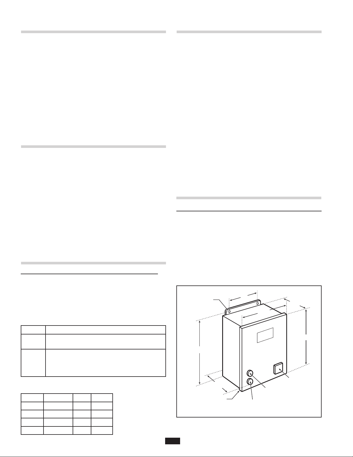
Mounting the Control Center
MOUNTING THE CONTROL CENTER
Use the flanges at the back of the control center enclo
sure and only mount panel in the upright vertical position
(door hinge is on the left - see Figure 1).
Locate control center within sight of disposer per local
codes.
If box is mounted to the sink table, recess the box so that
the buttons do not extend beyond the table’s edge.
Figure 1. Control center dimensions
2
-
Page 3
All pipe fittings are ½" NPT (National Pipe Taper)
SYPHON
BREAKER
FLOW
CONTROL
VALV
E
WA
TER
SOLENOID
VALVE
WATE
R
SUPPL
Y
ELECTRICA
L
SUPPL
Y
ELECTRICA
L
DISCONNEC
T
SWITC
H
CONTROL
CENTER
OPTIONAL
CONNECTION
DISPOSER
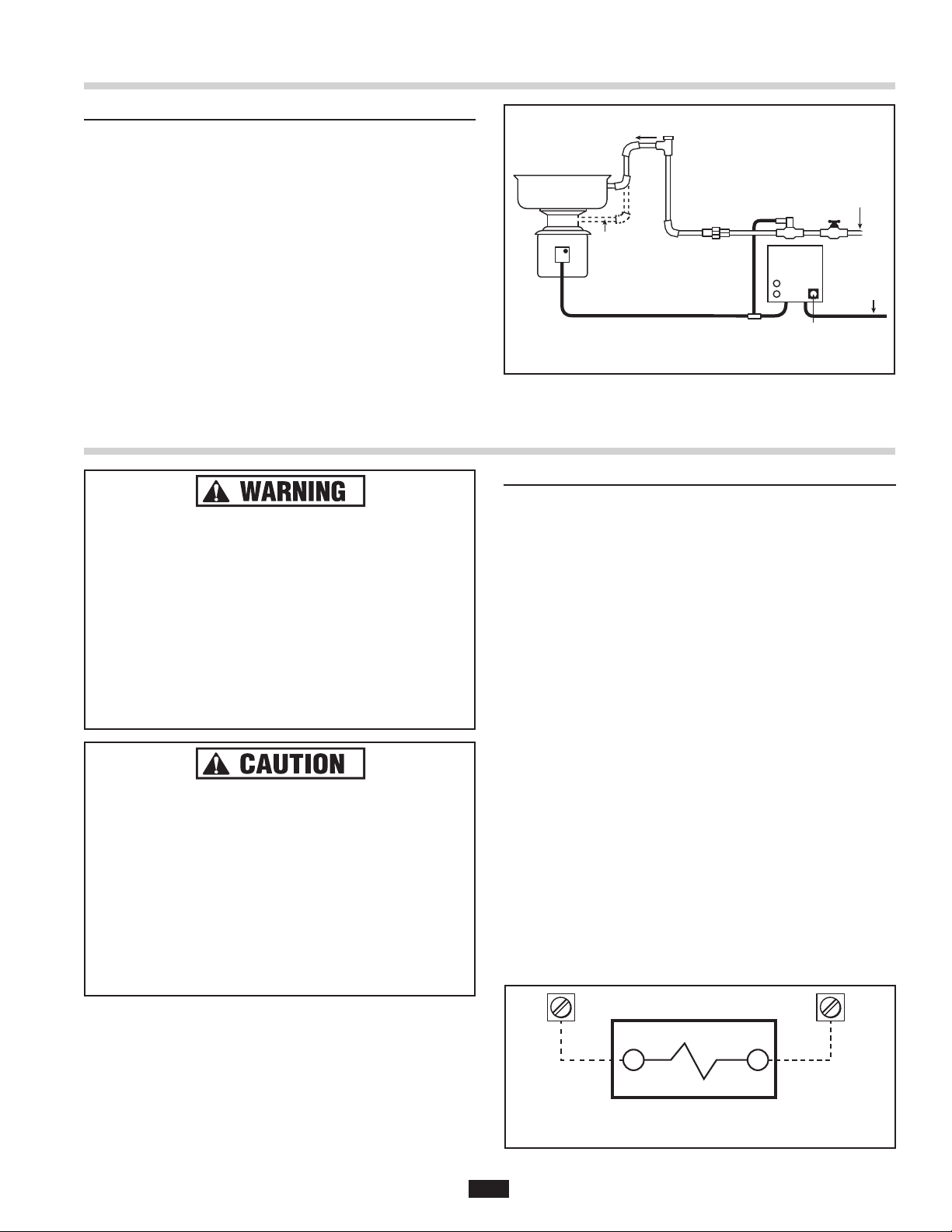
Plumbing Connections
WATER SOLENOID VALVE
24 COIL
4 5
PLUMBING CONNECTIONS
The solenoid valve is packed with the control center. The
flow control valve and syphon breaker are supplied with
all complete disposer packages (packaged separately).
The solenoid valve is supplied with a 24 V coil. Make cer
tain that the valves are plumbed according to the water
flow direction arrows marked on the valves, or the valves
will not function properly.
The flow control valve regulates all water flowing into the
disposer. This conserves water and prevents overload
ing. Check direction of water flow arrows.
A syphon breaker must be installed above the sink flood
plane per local plumbing codes. Check direction of water
flow arrows.
• Turn off the electrical supply to the disposer before
attempting any work on it. Use a voltmeter or
circuit tester to ensure that the power is off.
• All installation work must conform to local
plumbing and electrical codes.
• All control centers and disposers must be
carefully and permanently grounded.
• A properly fused disconnect must be installed at
the electrical supply source for the control center.
• Ensure that control center voltage and phase
match the disposer motor and electrical supply.
Check name plates on disposer and control
centers for voltage and phase specifications.
• Refer to the control center wiring diagrams in this
manual for correct connection.
• Use NEMA 4 watertight electrical connectors (not
supplied) when making electrical connections to
the control center.
NOTE: The MSLV control center has a door disconnect
switch, the disconnect switch must be in the off position
before the panel door can be opened. Power is still present at the disconnect until power is turned off at the supply
source.
ELECTRIC SHOCK
PROPERTY DAMAGE
-
-
Figure 2. Typical installation diagram
Electrical Connections
ELECTRICAL CONNECTIONS
The MSLV control center uses low-voltage (24 V) to oper
ate contactor coils, push buttons and solenoid valves. Red
wires denote the 24 V circuit.
Connect the incoming line power to the electrical door dis
connect switch and connect the disposer motor to labeled
terminal blocks in the control center. Use the appropriate
schematic wiring diagram, Figures 5, 6, 7 or 8. Wiring
diagram is also located on the inside door of the control
center. Wire the disposer motor for correct voltage using the
connection diagram inside the motor terminal box.
Wire per local electrical code using 7/8" diameter holes in
the bottom of the control center cabinet, and install NEMA 4
watertight electrical connectors (not supplied).
centers and disposers must be carefully and permanently grounded.
After completing the connections, close door and fasten
all locking clamps. Replace disposer motor cover. Turn on
power.
WATER SOLENOID VALVE
Connect water solenoid valve as shown in Figure 3.
nect solenoid valve to the low-voltage solenoid terminals
numbers 4 and 5.
Figure 3. Solenoid valve connections to control panel terminals.
-
-
All control
Con-
3
Page 4

Time Delay Relay
2 3 4 5
6
6
33
1
2
4
SOL
NO
COM
ADJUSTMENT KNOB
24 V AC
The time delay relay may be used with the MSLV to delay
solenoid valve shut-off, providing a post flush. This helps
prevent drain line stoppages and is beneficial when ground
food waste must travel through many bends or down a
long horizontal run in the drain line. It is adjustable from 0
to 10 minutes and factory-set to provide an approximately
5-minute delay. To adjust the time, SHUT OFF ELECTRIC
POWER. Inside the unit, locate the adjustment knob. Turn
clockwise to increase delay or turn counterclockwise to
decrease delay. See figure 4 for wiring.
Ensure the voltage rating on the time delay and solenoid
valve are 24 volts.
OPERATING INSTRUCTIONS
TO START
1. Check to ensure disposer is free of foreign objects.
2. Ensure power is on.
3. Push start button. Disposer motor will run and water
will flow into the disposer.
TO STOP
1. Push stop button. Disposer motor and water will stop.
NOTE: If time delay relay is used, the water may
continue to flow into disposer for up to 10 minutes
.
Troubleshooting
This control center was inspected and tested under
operating conditions before shipment from factory. In case
of trouble, check the items listed below:
Disposer motor will not start and water does not flow.
A.
1. No incoming line power. Turn line power on.
2. Electrical disconnect switch is not on. Turn electrical
disconnect switch to ON position.
3. Control circuit fuse FNA2 is blown. Replace fuse.
B. Disposer motor stops while grinding but water
continues to flow.
1. Press stop button and follow directions in disposer
installation manual for unjamming disposer.
2. Disposer motor overload has tripped. Follow
instructions for C1, below.
Figure 4. Time delay relay connections
Operating Instructions
Please read the disposer operating instructions and
train personnel before operating the disposer.
The operating instructions are supplied with the disposer
and include:
• Disposer Operation
• How to restart the disposer after a jam condition.
PERSONAL INJURY
• Turn power off before clearing a jam, removing an
object from the disposer, or pressing the red reset
button (see Troubleshooting)
• Disconnect electricity before adjusting set points.
• Allow only trained personnel to operate the disposer.
• Use baffles and guarding to avoid splashing and
ejection of materials.
• Do not put fingers or hands into the disposer.
• When attempting to remove objects from a disposer,
use long-handled tongs or pliers.
.
ELECTRICAL SHOCK / PROPERTY DAMAGE
• Troubleshooting other than what is recommended
in this section should only be performed by
qualified service personnel.
• Further troubleshooting performed by untrained
personnel could result in electric shock or damage
to the control center.
• All electrical checks must be performed by a
qualified profession
al.
C. Disposer motor will not start but water flows.
1. Overload protector on the disposer may have tripped.
Press the stop button. Locate the red reset button
on front of disposer electrical cover. Press to reset. If
the motor had been running, wait five minutes for the
motor and overload to cool down.
2. Disposer is jammed. Press the red stop button and
follow the directions for unjamming supplied with the
disposer.
D. Overload trips frequently
1. Do not overload the disposer with excess amounts of
garbage and water.
If trouble still persists, call your nearest In-Sink-Erator
Authorized Service Agency. For the location of your nearest
service agency, call toll-free 1-800-845-8345.
4
Page 5

(FNA2)
| ON
| OFF
4
GROUND
H1 H3 H2 H4
X2 XF
FUSE
2 3 4 5 M1 M
2
3
6
6
2
L1
INCOMING
L2
L1 L2
L1
L2
M1
M2
5
6
6
5
5
4
4
L2
L1
DISPOSER
MOTO
R
OPTIONAL
SOLENOID
VALVE
START
STOP
MODEL NO. MSLV-5
120 W, 1 Ø, ½-2 HP
PART NO. 1418
6
NEMA 4
IN-SINK-ERATOR DIVISION
EMERSON ELECTRIC CO
.
4700 21ST STREE
T
RACINE, WI. 53406-5093
Wiring Diagrams
ELECTRIC SHOCK
• Turn off the electrical supply to the disposer before
attempting any work on it. Use a voltmeter or
circuit tester to ensure that the power is off.
• Installation must conform with local electrical
codes.
• All control centers and disposers must be carefully
and permanently grounded.
• A properly-fused disconnect must be installed
at
the electrical supply source for the control center.
PROPERTY DAMAGE
• Ensure that the control center voltage and phase
match the disposer motor and electrical supply.
Check nameplates on disposers and control
centers for voltage and phase specification.
• The disposer motor wiring connection is shown in
the disposer terminal box.
Note: • Red wires = Low Voltage (24 V) control
• Black wires = Line voltage (120 V) control
Model MSLV
120 V
1 Ø
1/2 to 2 hp
Figure 5. 120 V, 1 Ø, ½ to 2 hp Wiring Diagram
Call Toll Free 1-800-845-8345
for the nearest In-Sink-Erator
Authorized Service Center or
to reach Technical Support.
5
Page 6

(FNA2)
| ON
| OFF
4
GROUND
H1 H3 H2 H4
X2 XF
FUSE
2 3 4 5 M1 M2
3
6
6
2
L1
INCOMING
L2
L1 L2
L1
L2
M1
M2
5
6
6
5
5
4
4
L2
L1
DISPOSER
MOTO
R
OPTIONAL
SOLENOID
VALVE
START
STOP
MODEL NO. MSLV-6
208 – 240 W, 1 Ø, ½-2 HP
PART NO. 14186A
NEMA
4
IN-SINK-ERATOR DIVISION
EMERSON ELECTRIC CO
.
4700 21ST STREET
RACINE, WI. 53406-5093
Wiring Diagrams
ELECTRIC SHOCK
• Turn off the electrical supply to the disposer before
attempting any work on it. Use a voltmeter or
circuit tester to ensure that the power is off.
• Installation must conform with local electrical
codes.
• All control centers and disposers must be carefully
and permanently grounded.
• A properly-fused disconnect must be installed
at
the electrical supply source for the control center.
Model MSLV
208 – 240 V
1 Ø
1/2 to 2 hp
PROPERTY DAMAGE
• Ensure that the control center voltage and phase
match the disposer motor and electrical supply.
Check nameplates on disposers and control
centers for voltage and phase specification.
• The disposer motor wiring connection is shown in
the disposer terminal box.
Note: • Red wires = Low Voltage (24 V) control
• Black wires = Line voltage (208 – 240 V) control
Call Toll Free 1-800-845-8345
for the nearest In-Sink-Erator
Authorized Service Center or
to reach Technical Support.
Figure 6. 208 – 240 V, 1 Ø, ½ to 2 hp Wiring Diagram
6
Page 7

(FNA2)
L3
L1
L2
L3
| ON
| OFF
4
GROUND
H1 H3 H2 H4
X2 XF
FUSE
2 3 4 5
NC
M1 M2 M3
3
6
6
2
L1
INCOMING
L2
L1
L2
L3
M1
M2
5
6
6
5
5
4
4
L2
L1
DISPOSER
MOTO
R
OPTIONAL
SOLENOID
VALVE
START
STOP
M3
NC
MODEL NO. MSLV-7
208 – 240 W, 3 Ø, ½-10 HP
PART NO. 14186B
NEMA
4
IN-SINK-ERATOR DIVISION
EMERSON ELECTRIC CO
.
4700 21ST STREE
T
RACINE, WI. 53406-5093
Wiring Diagrams
ELECTRIC SHOCK
• Turn off the electrical supply to the disposer before
attempting any work on it. Use a voltmeter or
circuit tester to ensure that the power is off.
• Installation must conform with local electrical
codes.
• All control centers and disposers must be carefully
and permanently grounded.
• A properly-fused disconnect must be installed
at
the electrical supply source for the control center.
PROPERTY DAMAGE
• Ensure that the control center voltage and phase
match the disposer motor and electrical supply.
Check nameplates on disposers and control
centers for voltage and phase specification.
• The disposer motor wiring connection is shown in
the disposer terminal box.
Note: • Red wires = Low Voltage (24 V) control
• Black wires = Line voltage (208-240 V) control
Model MSLV
208 – 240 V
3 Ø
1/2 to 10 hp
Figure 7. 208 – 240 V, 3 Ø, ½ to 10 hp Wiring Diagram
7
Call Toll Free 1-800-845-8345
for the nearest In-Sink-Erator
Authorized Service Center or
to reach Technical Support.
Page 8

(FNA2)
L3
L1
L2
L3
| ON
| OFF
4
GROUND
H1 H3 H2 H4
X2 XF
FUSE
2 3 4 5
NC
M1 M2 M3
3
6
6
2
L1
INCOMING
L2
L1
L2
L3
M1
M2
5
6
6
5
5
4
4
L2
L1
DISPOSER
MOTO
R
OPTIONAL
SOLENOID
VALVE
START
STOP
M3
NC
MODEL NO. MSLV-8
380-460w, 3 Ø, ½-10 HP
PART NO. 14186C
NEMA
4
IN-SINK-ERATOR DIVISION
EMERSON ELECTRIC CO
.
4700 21ST STREET
RACINE, WI. 53406-5093
Wiring Diagrams
ELECTRIC SHOCK
• Turn off the electrical supply to the disposer before
attempting any work on it. Use a voltmeter or
circuit tester to ensure that the power is off.
• Installation must conform with local electrical
codes.
• All control centers and disposers must be carefully
and permanently grounded.
• A properly-fused disconnect must be installed
at
the electrical supply source for the control center.
Model MSLV
380 – 460 V
3 Ø
1/2 to 10 hp
PROPERTY DAMAGE
• Ensure that the control center voltage and phase
match the disposer motor and electrical supply.
Check nameplates on disposers and control
centers for voltage and phase specification.
• The disposer motor wiring connection is shown in
the disposer terminal box.
Note: • Red wires = Low Voltage (24 V) control
• Black wires = Line voltage (380 – 460 V) control
Call Toll Free 1-800-845-8345
for the nearest In-Sink-Erator
Authorized Service Center or
to reach Technical Support.
8
Figure 8. 380 – 460 V, 3 Ø, ½ to 10 hp Wiring Diagram
 Loading...