

Page 1

ISE
IN-SINK-ERATOR
Commercial
Products Group
COMMERCIAL DISPOSER
CONTROL CENTER
Installation Manual
Model CC-202C
WARNING
CAUTION
Please be certain that the person who installs or uses this appliance carefully reads and understands the Safety Instructions
contained in this manual.
The Warning signal alerts you to potential hazards or unsafe practices which, if not avoided, could
result in severe personal injury or death.
The Caution signal alerts you to hazards or unsafe practices which, if not avoided, may result in
minor personal injury or property damage.
Part No. 14125 - February, 1998
Page 2
FEATURES / MOUNTING THE CONTROL CENTER
The contro
l center models and specifications are shown in Table
2
PUSH BUTTON OPERATION
INTRODUCTION
The CC-202C Control Center is UL approved for use with ISE
Commercial Food Waste Disposers. See Table 1 for approved
combinations. The control center operates the disposer. Its main
functions are:
• To start and stop the disposer. Using flanges at the back of the control center enclosure and
• To reverse the direction of the disposer motor automatically
upon restart.
• To start the water flow to the disposer.
TABLE 7. Approved Disposer and Control Center Combinations
Model Waste Disposer Model
Push black button to start disposer.
Push red button to stop disposer.
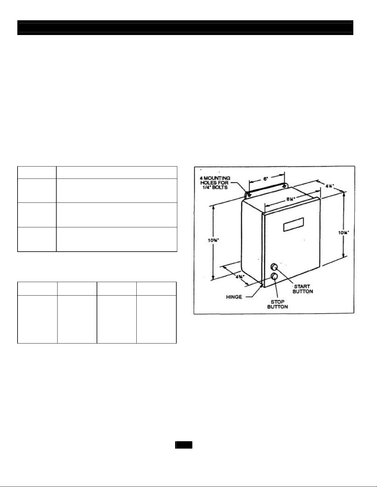
MOUNTING THE CONTROL CENTER
only mount panel in the upright vertical position (door hinge is
on the left). See Figure 1.
Locate control center within sight of disposer per local codes.
If box is mounted to the sink table, recess the box so that the
buttons do not extend beyond the table's edge.
CC-202C-1 CC202C-2
CC-202C-3 CC202C-4
CC-202C-5 CC202C-6
SS50-26, SS75-27. SS100-28, SS125-25, SS150-34,
SS150-38, SS200-27. SS200-31
SS50-27, SS75-28, SS100-29, SS125-26, SS150-36,
SS150-39, SS200-29, SS200-32
SS300-25, SS300-27, SS500-28, SS500-30. SS75013, SS750-15. SS1000-10, SS1000-12
TABLE 2. Electrical Specifications
Model Voltage Phase hp
CC-202C-1 120V 1 1/2-2
CC-202C-2 208/230 V 1 1/2-2
CC-202C-3 208/230 V 3 1/2-5
CC-202C-4 380/460 V 3 1/2-5
CC-202C-5 208/230 V 3 7 ½ -10
CC-202C-6 380/460 V 3 7 ½ - 10
FIGURE 1. Control Center Dimensions
FEATURES
AUTOMATIC REVERSE
The disposer motor will reverse its direction of rotation
automatically upon restart.
ENCLOSURE
Stainless steel NEMA 4 construction.
2
Page 3
ELECTRICAL CONNECTIONS
• Turn off the electrical supply to the disposer before attempting any
work on it. Use a voltmeter or circuit tester to ensure that the
power is off.
• All installation work must conform to local plumbing and electrical
codes.
• All control centers and disposers must be carefully and
permanently grounded.
• A properly fused disconnect must be installed at the electrical
supply source for the control center.
WARNING
ELECTRICAL SHOCK PROPERTY DAMAGE
ELECTRICAL CONNECTIONS
Connect the incoming line power and disposer motor to the labeled
terminal block in the control center. Use appropriate voltage and phase
electrical connection diagrams 5, 6, 7 or 8. Wire the disposer motor. For
correct voltage use the connection diagram inside the motor terminal
box.
• Ensure that control center voltage and phase match the disposer
motor and electrical supply. Check name plates on disposer and
control centers for voltage and phase specifications.
• Refer to the control center wiring diagrams in this manual for
correct connection.
• Use NEMA 4 watertight electrical connectors (not supplied) when
making electrical connections to the control center.
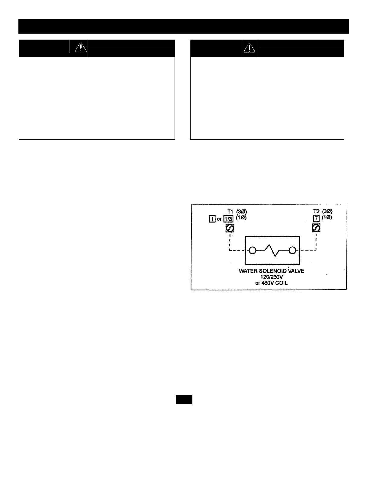
WATER SOLENOID VALVE
Connect solenoid valve to the control terminal numbers as shown
in Figure 3. Make sure the solenoid valve is the same voltage as
the control panel and supply power.
CAUTION
Connect water solenoid valve as shown in Figure 6.
Wire per local electrical code using 1-1/8" diameter holes in bottom of
control center cabinet and install NEMA 4 watertight electrical
connectors. (Not supplied).
After completing the connections, close door and fasten all locking
clamps. Replace disposer motor cover. Turn on power.
FIGURE 3. Solenoid valve connections to control panel terminals
4
Page 4

OPERATING INSTRUCTIONS / TROUBLESHOOTING
6
personnel before operating the disposer. The operating
instructions include:
• Disposer operation:
• How to restart the disposer after a jam condition.
PERSONAL INJURY
• Allow only trained personnel to operate disposer.
• Use baffles and guarding to avoid splashing and ejection of
materials.
• Do not put fingers or hands into the disposer.
• When attempting to remove objects from a disposer, use longhandled tongs or pliers.
• Turn power off before clearing a jam, removing an object from the
disposer or pressing the red reset button. (See Troubleshooting this
page).
• Disconnect electricity before adjusting set points.
ELECTRICAL SHOCK/PROPERTY DAMAGE
• Troubleshooting other than what is recommended in this section
should only be performed by qualified service personnel.
• All electrical checks must be performed by a qualified professional.
C. Disposer will not start but water flows.
1. Overload protector on the disposer may have tripped. Press
stop button. Locate red reset button on front of disposer
electrical cover. Press to reset. If motor had been running, wait
five minutes for the motor and overload to cool down.
2. Disposer is jammed. Press stop button and follow directions for
unjamming supplied with disposer.
WARNING Please read the disposer operating instructions and train your
OPERATING INSTRUCTIONS
TO START
1. Check to ensure disposer is free of foreign objects.
2. Ensure power is on.
3. Push start button. Disposer motor will run and water will flow into the
disposer.
TO STOP
1. Push stop button. Disposer motor and water will stop.
TROUBLESHOOTING
This control center was inspected and tested under operating conditions
before shipment from the factory. In case of trouble, check the items
listed below.
A. Disposer motor will not start and water does not flow.
1. No incoming line power. Turn line power on.
B. Disposer motor stops while grinding but water continues to flow.
D. Water flows constantly before start button is pushed.
1. Water solenoid valve is installed backward. Water flow should
be in the direction of the arrow on valve.
2. Water solenoid valve is wired incorrectly. Recheck wiring
diagram on page 7, 8 or 9.
E. Overload trips frequently.
1. Do not overload disposer with excess amounts of garbage and
water. (See disposer instructions for recommended water
flows.)
If trouble still persists, call your nearest ISE Authorized Service
Agency. For the location of your nearest service agency, call toll-free 1800-558-5700.
1. Disposer is jammed. Press stop button and follow directions for
unjamming supplied with the disposer.
2. Disposer motor overload protector has tripped. Follow instruction
in C1.
Page 5

SCHEMATIC WIRING DIAGRAMS
MODEL N
o. CC202
-
2
WARNING
ELECTRICAL SHOCK PROPERTY DAMAGE
• TURN OFF ALL ELECTRICAL SUPPLY TO THE DISPOSER BEFORE ATTEMPTING
ANY WORK ON IT. USE A VOLTMETER OR CIRCUIT TESTER TO ENSURE THAT
POWER IS OFF.
• INSTALLATION MUST CONFORM TO LOCAL ELECTRICAL CODES.
• ALL CONTROL CENTERS AND DISPOSERS MUST BE CAREFULLY AND
PERMANENTLY GROUNDED.
• A PROPERLY FUSED DISCONNECT MUST BE INSTALLED AT THE ELECTRICAL
CAUTION
• ENSURE THAT THE CONTROL CENTER VOLTAGE AND PHASE MATCH THE
DISPOSER MOTOR AND ELECTRICAL SUPPLY. CHECK NAMEPLATES ON
DISPOSERS AND CONTROL CENTERS FOR VOLTAGE AND PHASE
SPECIFICATION.
• THE DISPOSER MOTOR WIRING CONNECTION IS SHOWN IN THE DISPOSER
TERMINAL BOX.
208/230V, 1 Ø, 1/2 - 2 HP
IN-SINK-ERATOR DIVISION
EMERSON ELECTRIC CO.
4700 21st. STREET
RACINE, WI 53406-5093
8
Page 6

SCHEMATIC WIRING DIAGRAMS
SUPPLY SOURCE FOR THE CONTROL CENTER.
MODEL N
o. CC202
IN-SINK
-
ERATOR DIVISION
WARNING
ELECTRICAL SHOCK PROPERTY DAMAGE
• TURN OFF ALL ELECTRICAL SUPPLY TO THE DISPOSER BEFORE ATTEMPTING
ANY WORK ON IT. USE A VOLTMETER OR CIRCUIT TESTER TO ENSURE THAT
POWER IS OFF.
• INSTALLATION MUST CONFORM TO LOCAL ELECTRICAL CODES.
• ALL CONTROL CENTERS AND DISPOSERS MUST BE CAREFULLY AND
PERMANENTLY GROUNDED.
• A PROPERLY FUSED DISCONNECT MUST BE INSTALLED AT THE ELECTRICAL
CAUTION
• ENSURE THAT THE CONTROL CENTER VOLTAGE AND PHASE MATCH THE
DISPOSER MOTOR AND ELECTRICAL SUPPLY. CHECK NAMEPLATES ON
DISPOSERS AND CONTROL CENTERS FOR VOLTAGE AND PHASE
SPECIFICATION.
• THE DISPOSER MOTOR WIRING CONNECTION IS SHOWN IN THE DISPOSER
TERMINAL BOX.
380/460V, 3 Ø, 1/2 - 5 HP
EMERSON ELECTRIC CO.
4700 21st STREET
RACINE, WI 53406-5093
10
Page 7

SCHEMATIC WIRING DIAGRAM
OL CENTER VOLTAGE AND PHASE MATCH
ELECTRICAL SUPPLY SOURCE FOR THE CONTROL CENTER.
WARNING
ELECTRICAL SHOCK PROPERTY DAMAGE
TURN OFF ALL ELECTRICAL SUPPLY TO THE DISPOSER BEFORE
•
ATTEMPTING ANY WORK ON IT. USE A VOLTMETER OR CIRCUIT
•
INSTALLATION MUST CONFORM TO LOCAL ELECTRICAL CODES.
ALL CONTROL CENTERS AND DISPOSERS MUST BE CAREFULLY AND
•
PERMANENTLY GROUNDED.
A PROPERLY FUSED DISCONNECT MUST BE INSTALLED AT THE
•
CAUTION
ENSURE THAT THE CONTR
•
THE DISPOSER MOTOR AND ELECTRICAL SUPPLY. CHECK
NAMEPLATES ON DISPOSERS AND CONTROL CENTERS FOR
VOLTAGE AND PHASE SPECIFICATION.
• THE DISPOSER MOTOR WIRING CONNECTION IS SHOWN IN THE
DISPOSER TERMINAL BOX.
MODEL No. CC202
380/460V. 3 Ø,7-1/2 - 10 HP
IN-SINK-ERATOR DIVISION
EMERSON ELECTRIC CO.
4700 21st STREET
RACINE. WI 53406-5093
 Loading...