

Page 1
DISPOSER CONTROL CENTERS
SERVICE MANUAL
CC-101 SERIES
COMMERCIAL DISPOSER
CONTROL CENTERS
(INCLUDES WIRING DIAGRAMS)
SEE PREFACE FOR MODEL REFERENCE
IN-SINK-ERATOR DIVISION
EMERSON ELECTRIC CO.
4700 21st STREET, RACINE, WI 53406
Page 2

TABLE OF CONTENTS
2 Preface
2-1
CC-101 B
15-2
SECTION PAGE NO.
1 Safety Precautions 1-1
3 General Information 3-1
4 Wiring Diagrams 4-1
5 Plumbing, Motor and Line Voltage Connections 5-1
6 Subpanel Removal and Replacement 6-1
7 Component Description 7-1
8 Component Location 8-1
9 Operating Sequence 9-1
10 Component Testing and Replacement 10-1
11 Troubleshooting 11-1
12 Information Tips 12-1
13 Special Equipment 13-1
14 Glossary of Terms 14-1
15 Technical Data Sheets (How the Control Center Works)
CC-101 C & CC-101D 15-10
CC-101 E 15-18
CC-101 G & CC-101H 15-26
Page 3

PREFACE SECTION 2
A Control center is a device used to start and stop a commercial
disposer by the use of two push-button switches. It is commonly
referred to as a control panel and contains various electrical
component parts. The main functions of the control panel are to
reverse the direction of the disposer motor each time it is started,
start the water flow to the disposer, and allow it to flow for several
minutes after the disposer is turned off.
This manual includes CC-101 series control centers manufactured
since 1976 (i.e., CC-101 A through CC-101 G). Basic functions
remained the same throughout the CC-101 series, but component
parts changed, and eventually additional features were added.
NOTE
Once the function and purpose of each component is learned, control
centers manufactured before 1976 can also be diagnosed. If one
studies the B and C models, the remaining models become easier to
understand.
The model number of a control center can be found on the
specifications decal located on the inside or outside of the enclosure
door. All information on the decal (i.e., voltage, horsepower and
phase) must be noted prior to diagnosing. Variations of a control
center do not necessarily change the model number. Visual
inspection will determine which wiring diagram in this manual applies
to a given control center.
Factory assistance is available by calling 1-800-558-5700 (in
Wisconsin call 1-800-922-2331).
2-1
Page 4
GENERAL INFORMATION SECTION 3
GENERAL
This section is not intended as a complete installation guide.
Basic notes and guidelines for installation are provided here
for the purpose of checking or troubleshooting an existing
installation. Detailed installation instructions were provided
with the disposer; to obtain technical information not covered
in those instructions, contact the Factory.
NOTE
Neither the IN-SINK-ERATOR Company nor any of its Authorized
Service Centers performs original installations,
All installations are to be in accordance with local plumbing
and electrical codes.
NOTE
The disposer control center must be mounted within direct sight of
the disposer per local codes. Any remote control stations must also
be located within direct sight of the disposer per local codes.
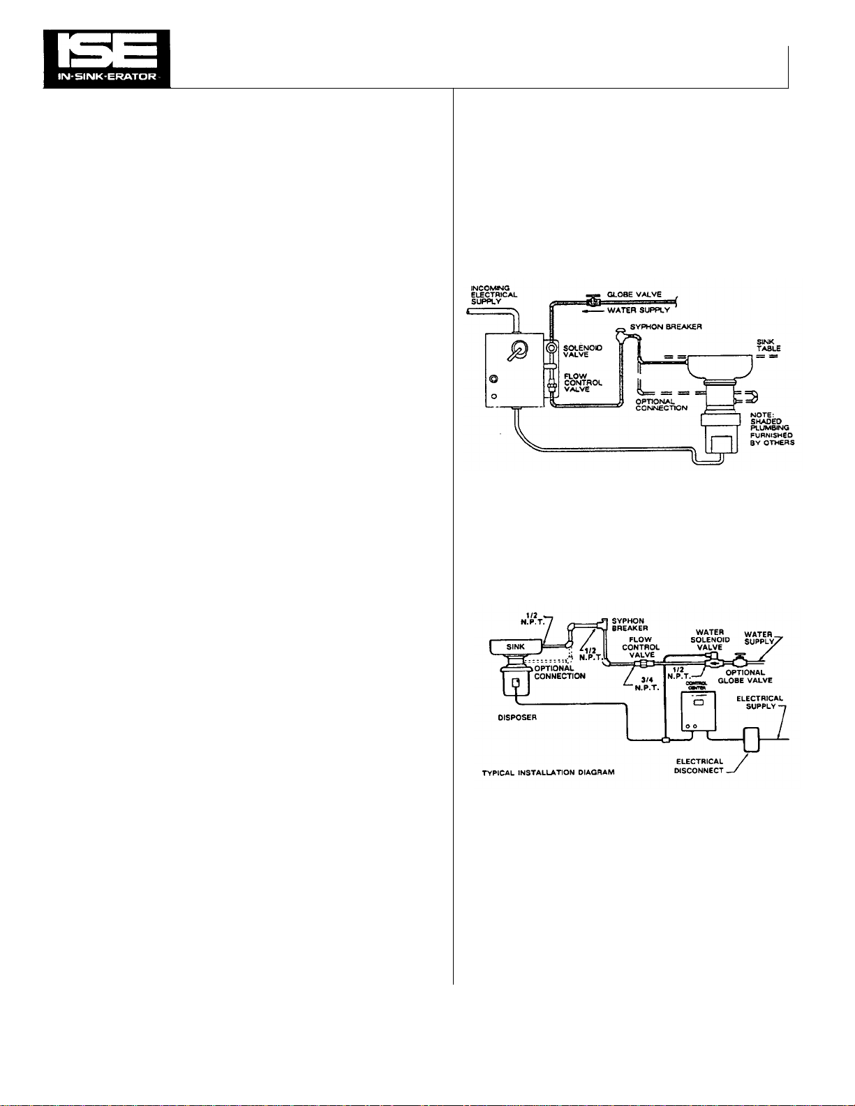
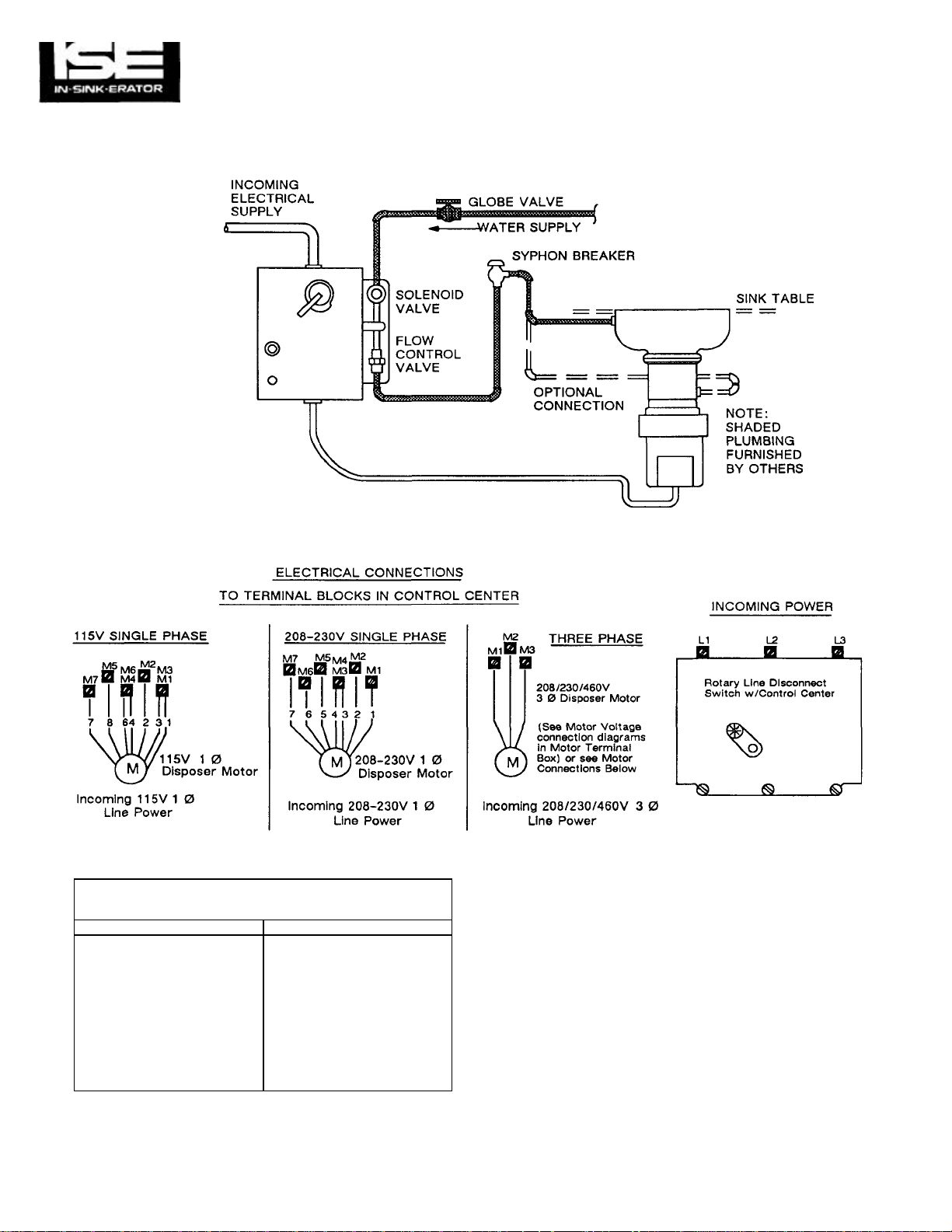
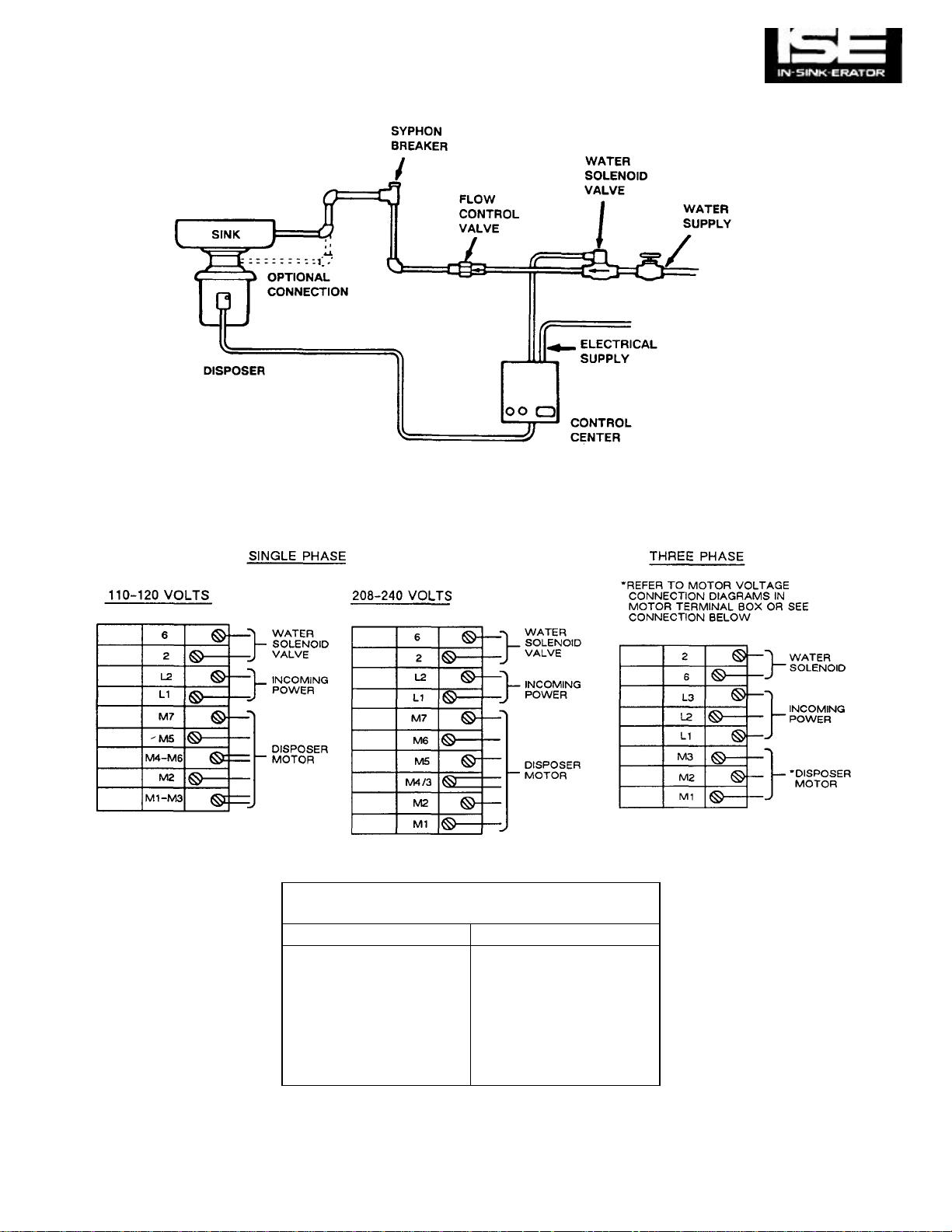
PLUMBING INSTALLATION
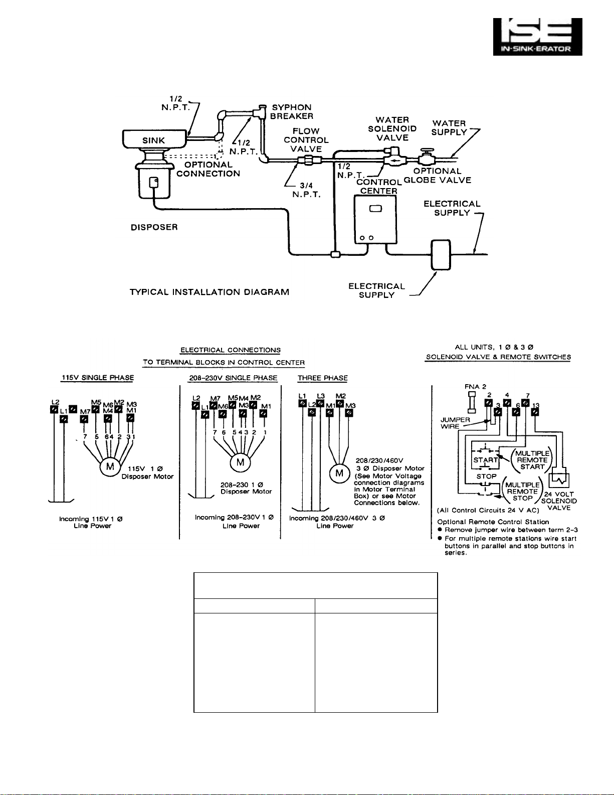
The following plumbing installation diagrams are included to
illustrate the plumbing connections of a typical installation.
Figure 5-1 shows an installation for a control center with an
enclosure-mounted solenoid valve (models CC-101A and
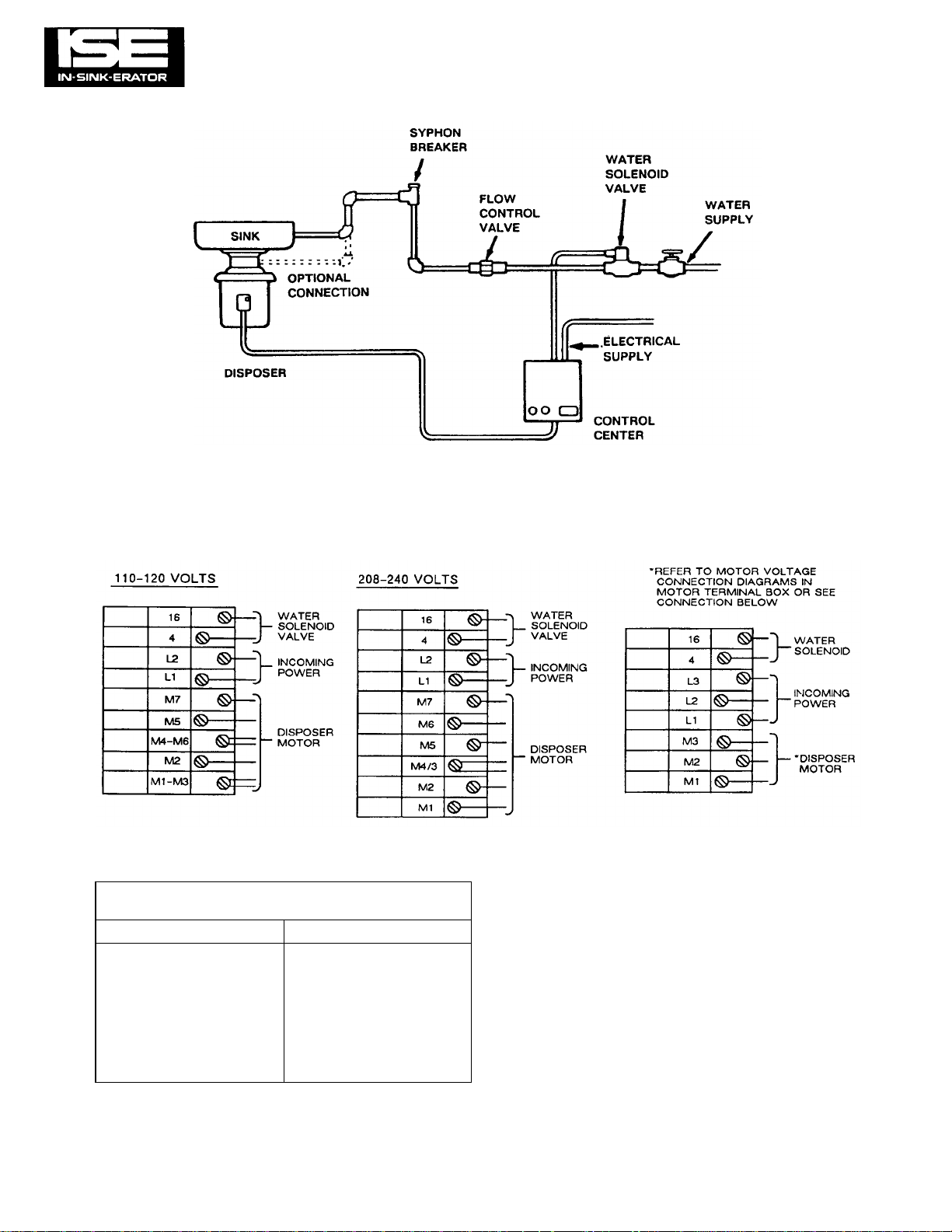
CC-101B). Figure 5-2 shows an installation with a remote-
mount solenoid valve (all other models).
The solenoid valve and flow control valve are each marked
with arrows showing the proper water flow direction. Both
valves must be installed so that the water flows through them
in the correct direction or the valves will not work properly.
Note that in all installations a syphon breaker (vacuum
breaker) must be installed above the sink flood plane per local
plumbing code.
Figure 5-1. Plumbing Connection Diagram, Typical
Installation (Enclosure-Mount Solenoid
Valve).
GENERAL ELECTRICAL INFORMATION
IN-SINK-ERATOR Commercial Disposer Control Centers are
shipped from the factory wired for a specific voltage and
phase. Please refer to the Control Center wiring diagrams in
this manual for the correct connections. (Disposer motor
connections will depend upon the operating voltage and
phase of the disposer.)
Figure 5-2. Plumbing Connection Diagram, Typical
Installation (Remote-Mount Solenoid
Valve).
3-1
Page 5
Figure
4-1.
CC-101B
Figure
4-2.
CC-101E
SECTION 3 GENERAL INFORMATION (Cont'd)
FEATURES
All CC-101 series Commercial Disposer Control Centers have
the following features:
Automatic Reversing Action — Automatically reverses the
disposer motor each time it is started to double the life of the
disposer grinding shredders.
Built-in Magnetic Starter — Automatically disengages electric
power to disposer if power loss occurs. Disposer must be
restarted.
Post Water Flush — Adjustable time delay relay automatically
permits water to flush sewer lines clear after disposer has
been turned off, eliminating sewer clogging.
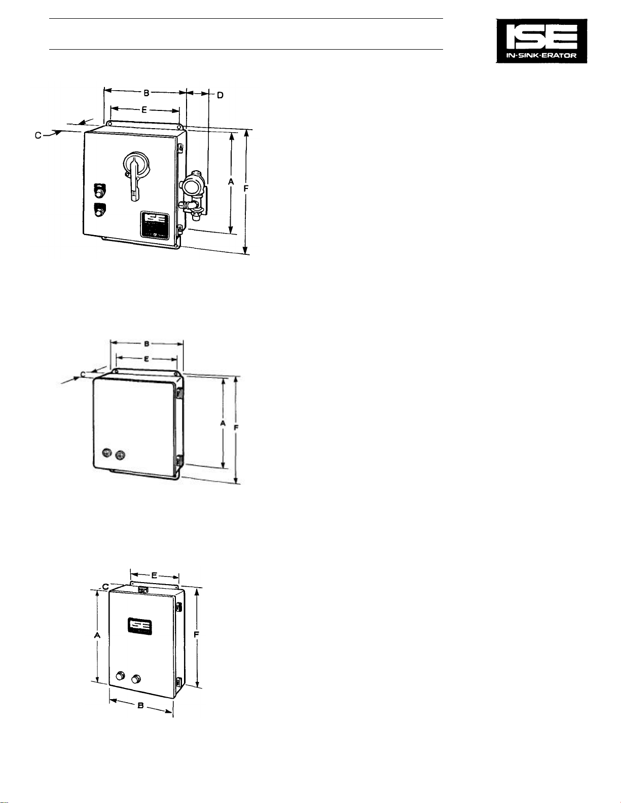
DIMENSIONS
Models CC-101 A and CC-101B
Length (A) 14"
Width (B) 12"
Depth (C) 6"
Width (D) 3-1/2"
5/16" Bolt Holes, Center to Center (E) 10"
5/16" Bolt Holes, Center to Center (F) 14-11/16"
Models CC-101C. CC-101D, and CC-101E
Length (A) 14"
Width (B) 12"
Depth (C) 6"
5/16" Bolt Holes, Center to Center (E) 10"
5/16" Bolt Holes, Center to Center (F) 14-11/16"
Other Features:
—Main flow control valve and solenoid valve mounted elsewhere in water line
Model CC-101G
Length (A) 15"
Width (B) 10"
Depth (C) 6"
5/16" Bolt Holes, Center to Center (E) 8"
5/16" Bolt Holes, Center to Center (F) 15-5/8"
Figure 4-3. CC-101G
3-2
Page 6

WIRING DIAGRAMS SECTION 4
The standard disposer motor voltages are 115/208/230 volts for
single phase electrical power and 208/230/460 volts for three phase
electrical power.
NOTE
Three phase contactors require three sets of contacts to carry line
voltage to the disposer, while single phase contactors require four
Circuitry and parts function on all control centers are identified
within their respective models. This applies to all component parts
controlled by or on the secondary voltage side of the transformer,
whether it is a 1 phase or 3 phase control center.
The wiring (circuitry) to the line voltage connections on the Reversing
contactors are identical on all 3 phase (only) contactors. The wiring
(circuitry) to the line voltage connections on the Reversing contactors
are identical on all 1 phase (only) contactors.
sets. Two identical contactors are utilized in every control center to
perform the function of reversing the disposer motor rotation.
Therefore, the wiring diagrams in this section (Figs. 4-12 through 4-
19) show 3 phase contactors but can be used to diagnose or trace
circuitry for 1 phase or 3 phase control centers, keeping in mind that
only the contactors are different from 1 phase to 3 phase. Refer to
Figs. 4-10 and 4-11 for 1 phase contactor connections.
All electrical connections must conform to local codes. Be
certain that all IN-SINK-ERATOR disposers and control centers
are carefully and permanently grounded.
CAUTION
ELECTRICAL INSTALLATION
BEFORE ANY ELECTRICAL WORK IS PERFORMED, REMOVE LINE
POWER FROM THE DISPOSER CONTROL CENTER BY TURNING OFF
THE CIRCUIT BREAKER. USE A VOLTMETER OR CIRCUIT TESTER TO
ENSURE THAT POWER IS OFF BEFORE PROCEEDING.
disposer motor voltage and phase must be the same as the
electrical supply. Check name-plates on both units for ratings.
All connections must conform to local codes. Ground the
disposer control center, the disposer, and all control boxes.
The following wiring diagrams are included to illustrate the electrical
connections for each standard model of disposer control center and
disposer motor. For each standard model of disposer control center,
wiring diagrams are shown to illustrate the most typical configurations. The wiring diagrams include motor connections. Since various
options can be custom ordered for a control enter, the wiring
diagrams for a particular model of control center do not reflect every
possible option. Additional wiring diagrams illustrating various special
(nonstandard) configurations of each model are provided in section
10 of this manual.
WARNING
CAUTION The control center and
4-1
Page 7
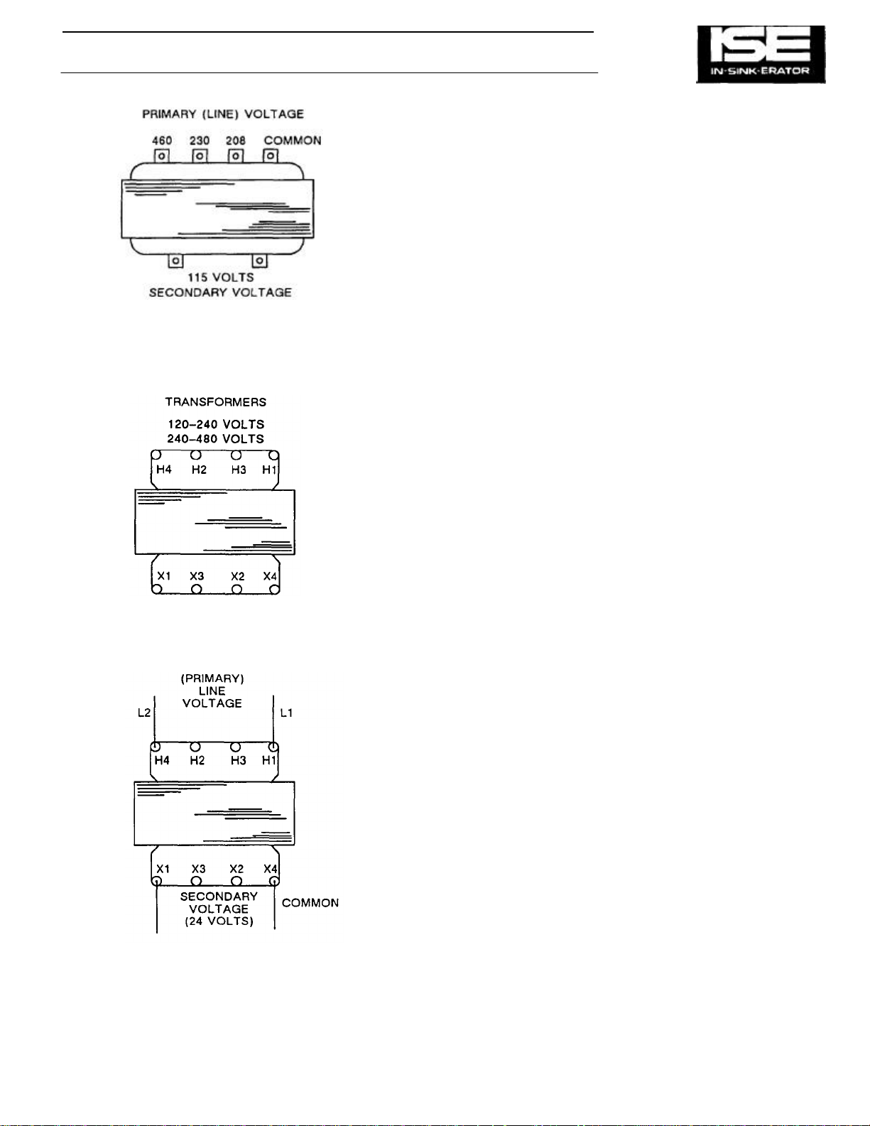
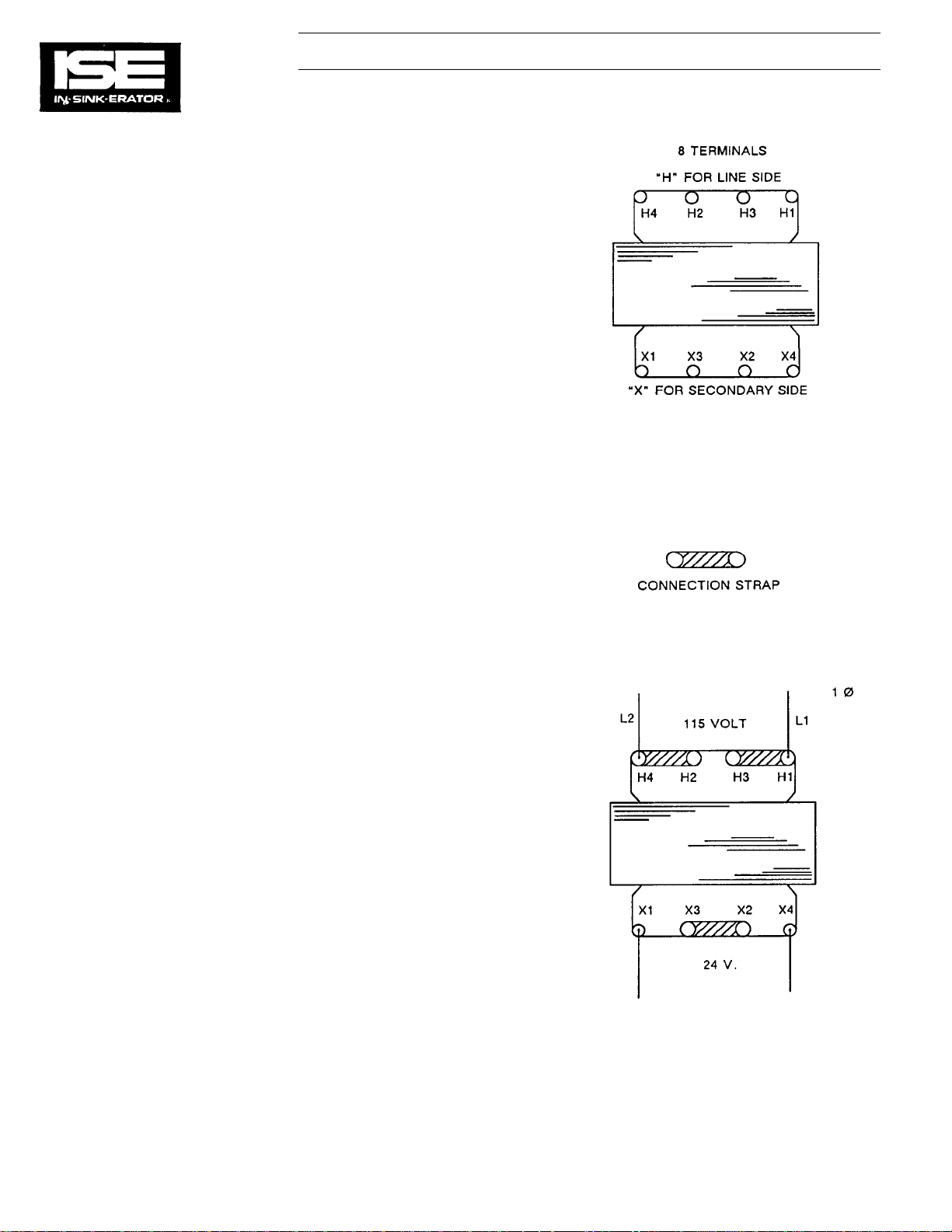
TRANSFORMER CONNECTIONS FOR
SECTION 4 WIRING DIAGRAMS (Cont'd)
Figure 4-3. 115 V Transformer Taps.
CONTROL CENTERS WITH 115 V CONTROL
CIRCUIT
Power lines carry line voltage to the primary terminals (also
called "taps") of the transformer. Line L2 is connected to the
common (ground) tap with Line L1 connected to the tap
coinciding with the line voltage.
The secondary taps on these transformers will always
supply 115 V ac to the load. This secondary voltage
operates the component parts in the control circuit. These
transformers are rated at 100 VA (Volt/Amperes), and can
be used for any 208 V/230 V/460 V incoming line. See
Figure 4-3.
TRANSFORMER CONNECTIONS FOR
CONTROL CENTERS WITH 24 V CONTROL
CIRCUITS
All control centers with 24 V secondary voltage require one
of two transformers. They appear identical. The specification
decal on the transformers will show 120 - 240 V or 240 -480
V (connections for line voltage). There is no reference to 208
V, but it is to be understood that 208 V connections will be
the same as 240 V. Whenever the recommended
transformer is used wiring diagrams furnished with the Control Center or in this manual apply.
Both 24 V secondary tap transformers can be used with 240
or 208 V inputs, but the terminal connections will change
and Control Center wiring diagrams may not necessarily apply. Whenever in doubt, refer to and use the connections
shown on the transformer specification decal. Connections
for input (primary) and output (secondary) voltages are the
same in all cases. See Figure 4-4 for connections.
RATED AT 100 VA
Figure 4-4. 24 V Transformer Taps.
4-2
Page 8
WIRING DIAGRAMS (Cont'd) SECTION 4
Terminal Connections
Transformer tap connections vary and are made in accordance with the applied line voltage. A conductive connection strap is normally used but 12 ga. wire can be
substituted (see Fig. 4-5).
Connections
Shown are the standard connections when the recommended
transformer is used. Refer to the illustrated parts list for specific
Control Centers. The voltage and phase of the Control Center
must be known. Secondary voltage for Figs. 4-5 through 4-8 is
24 V.
Figure 4-5. 115 V, 1 Phase.
4-3
Page 9
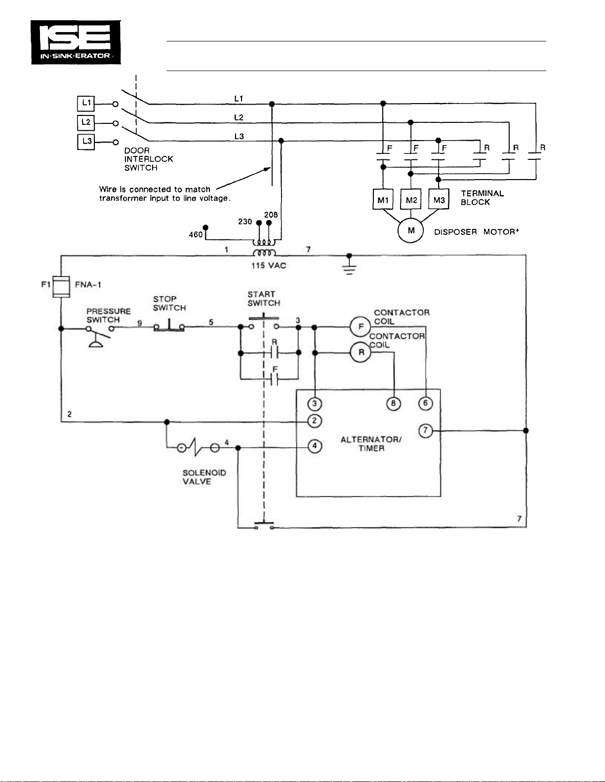
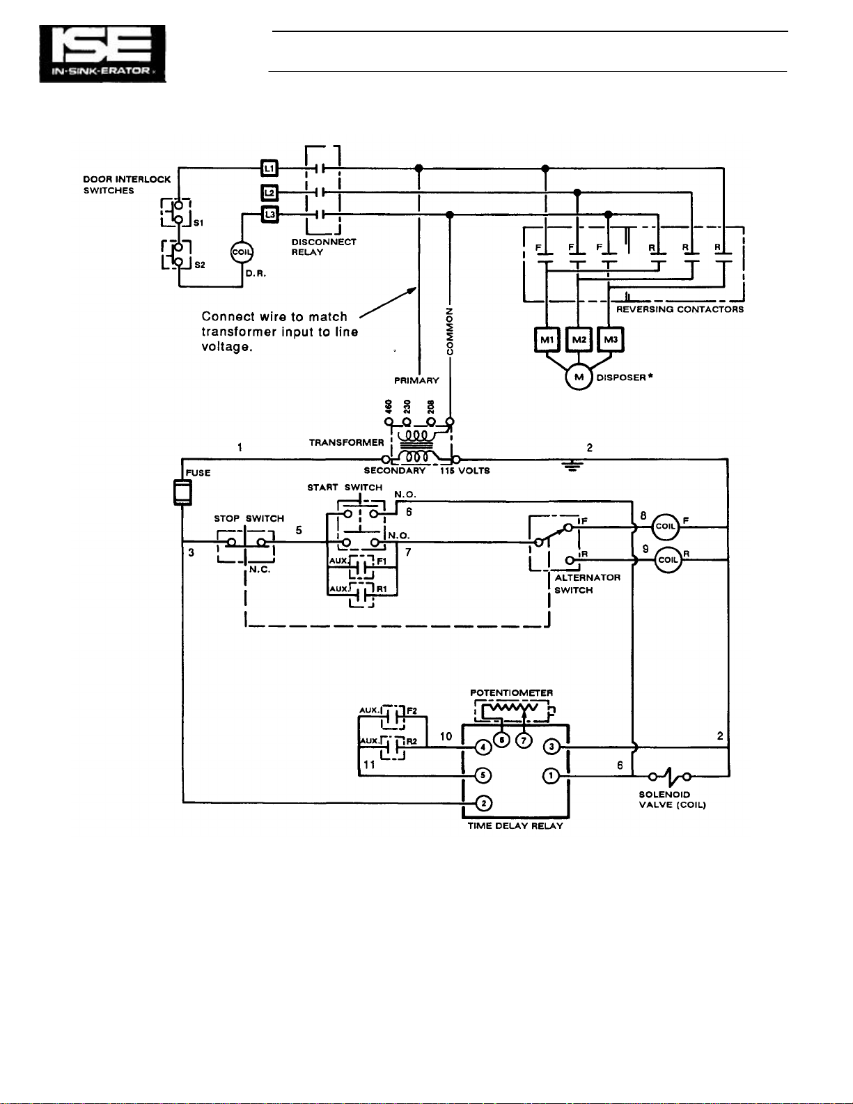
*SEE WIRING DIAGRAM IN DISPOSER
Figure
4-12.
Model CC
-
101A Wiring Diagram.
WIRING DIAGRAMS (Cont'd) SECTION 4
TERMINAL BOX FOR PROPER
CONNECTIONS OR FIG. 5-2.
4-7
Page 10
*SEE WIRING DIAGRAM IN DISPOSER
SECTION 4 WIRING DIAGRAMS (Cont'd)
TERMINAL BOX FOR PROPER
CONNECTIONS OR FIG. 5-2.
4-8
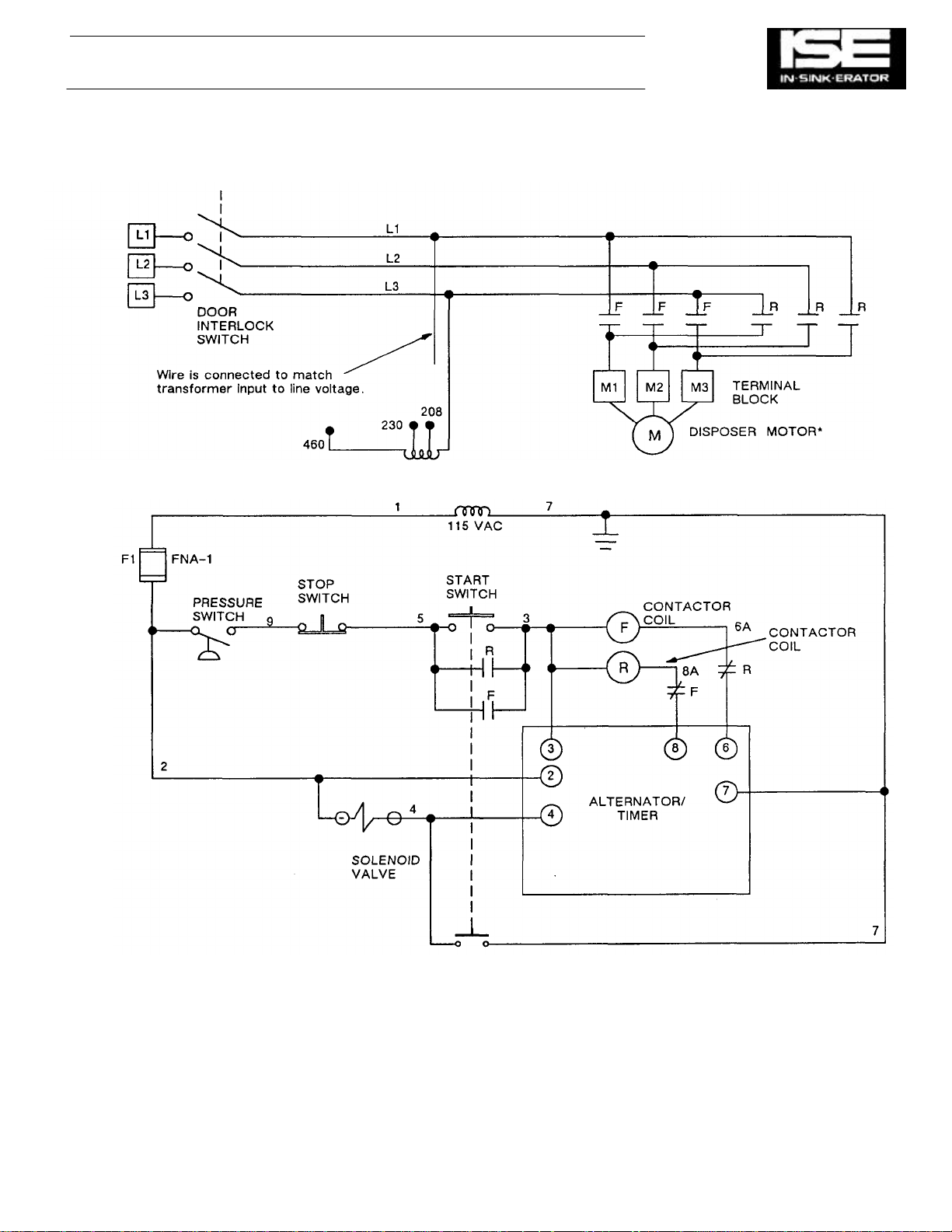
Figure 4-13. Model CC-101A Wiring Diagram (with Contactor Interlocks).
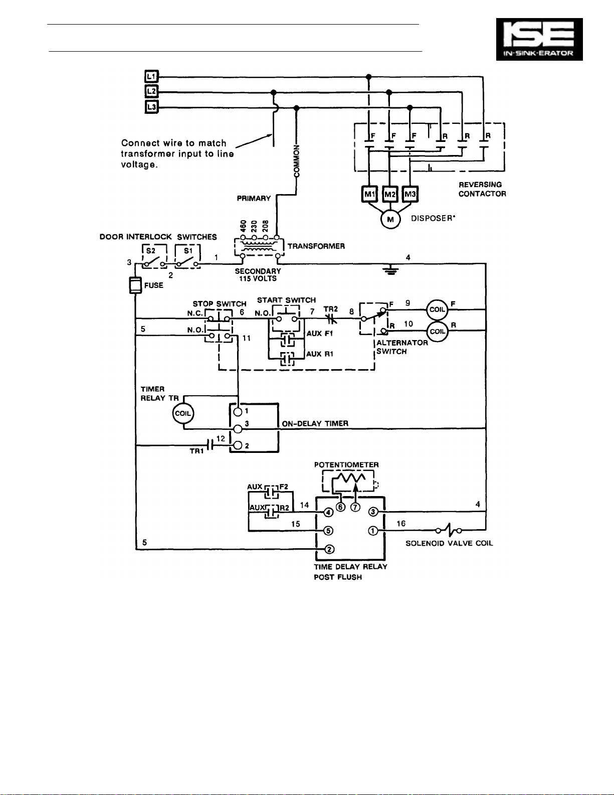
Page 11

*SEE WIRING DIAGRAM IN
Figure
4-14.
Model CC
-
101B Wiring Diagram.
WIRING DIAGRAMS (Cont'd) SECTION 4
DISPOSER TERMINAL BOX FOR
PROPER CONNECTIONS OR FIG.
5-2.
4-9
Page 12
SECTION 4 WIRING DIAGRAMS (Cont'd)
4-10
*SEE WIRING DIAGRAM IN DISPOSER
TERMINAL BOX FOR PROPER
CONNECTIONS OR FIG. 5-2.
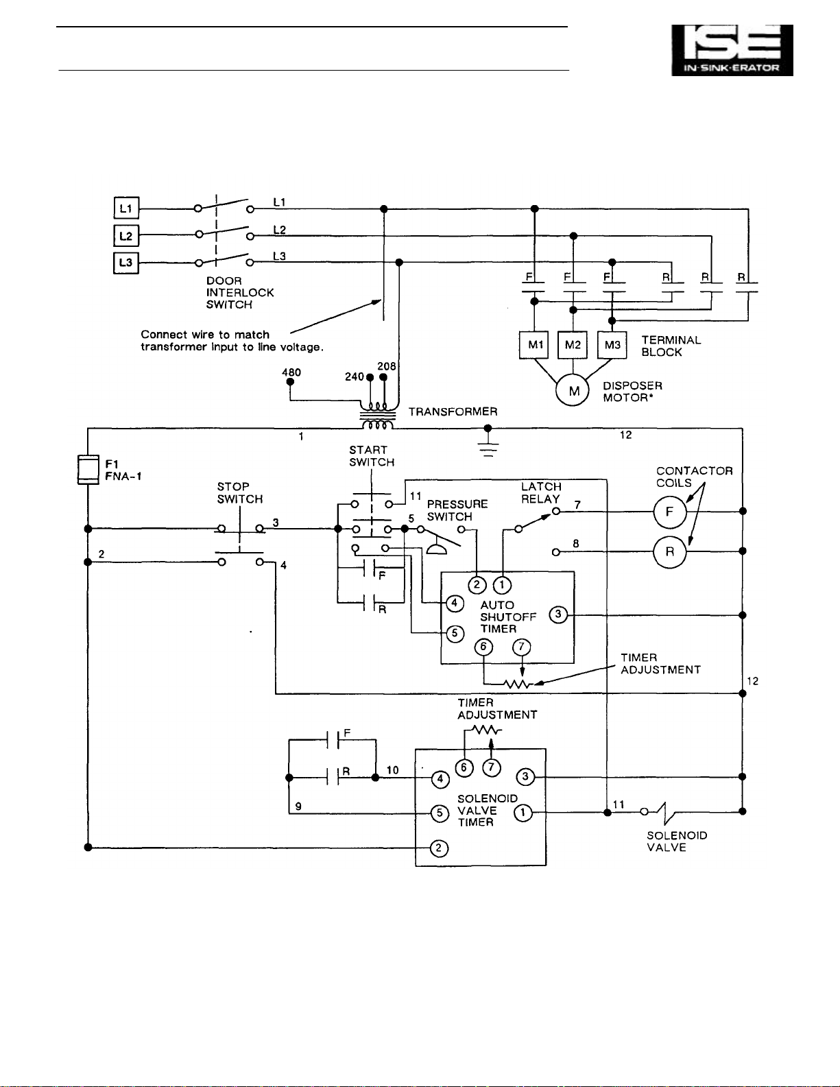
Figure 4-15. Model CC-101B Wiring Diagram (with Auto-Shutoff Timer).
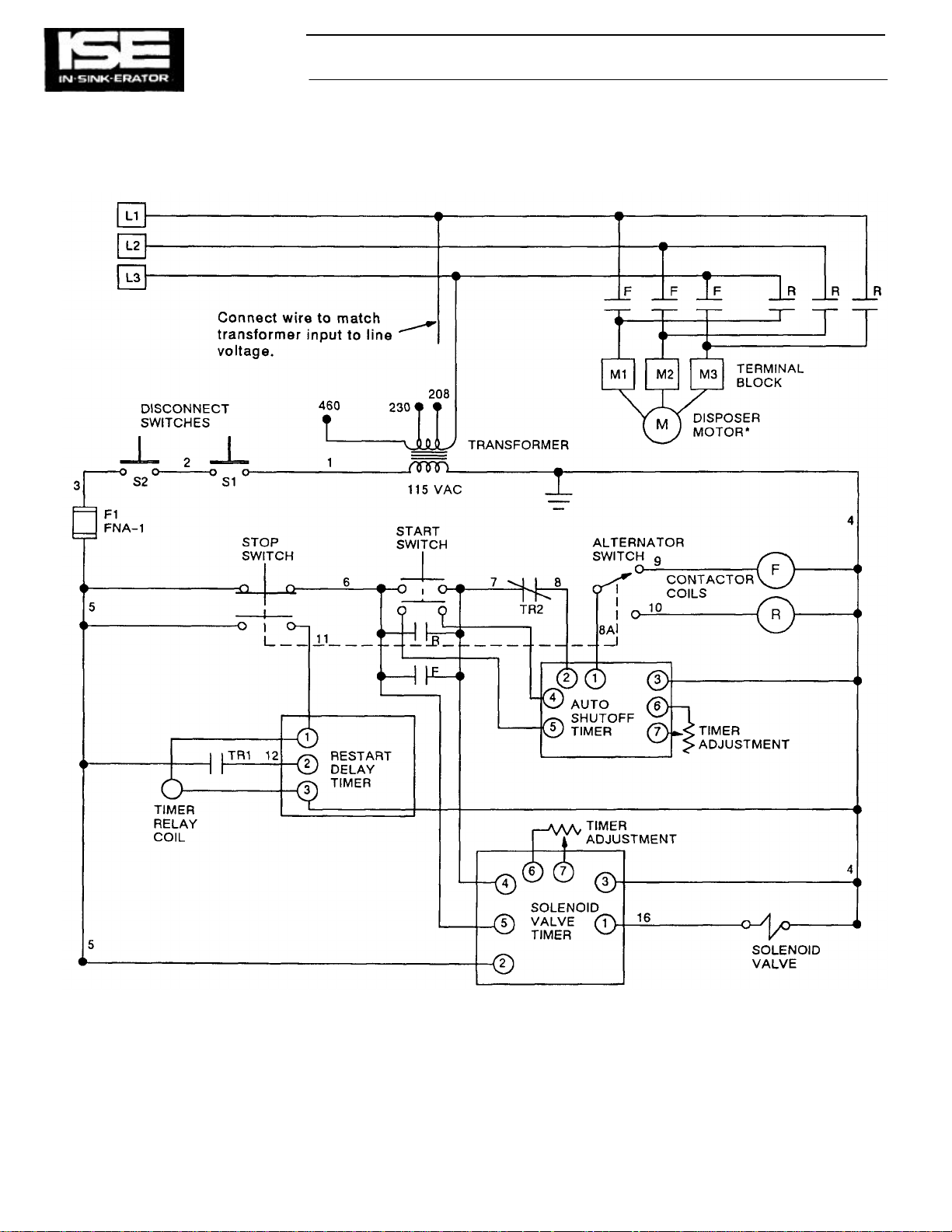
Page 13
WIRING DIAGRAMS (Cont'd) SECTION 4
*SEE WIRING DIAGRAM IN DISPOSER
TERMINAL BOX FOR PROPER
CONNECTIONS OR FIG. 5-5.
Figure 4-16. Modal CC-101C and CC-101D Wiring Diagram.
4-11
Page 14
*SEE WIRING DIAGRAM IN
Figure
4-17.
Model CC
-
101E Wiring Diagram.
4-
12
SECTION 4 WIRING DIAGRAMS (Cont'd)
DISPOSER TERMINAL BOX FOR
PROPER CONNECTIONS OR FIG.
5-7.
Page 15
WIRING DIAGRAMS (Cont'd) SECTION 4
•SEE WIRING DIAGRAM IN DISPOSER
TERMINAL BOX FOR PROPER
CONNECTIONS OR FIG. 5-7.
Figure 4-18. Model CC-101E Wiring Diagram (with Auto-Shutoff Timer).
4-13
Page 16
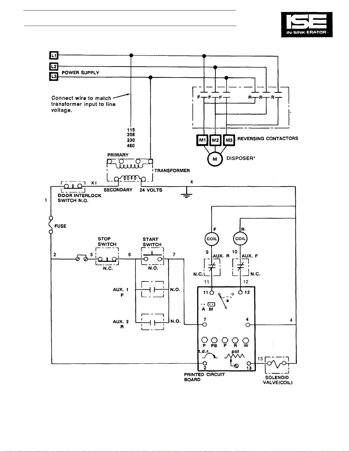
SECTION 4 WIRING DIAGRAMS (Cont'd)
•SEE WIRING DIAGRAM IN DISPOSER
TERMINAL BOX FOR PROPER
CONNECTIONS OR FIG. 5-9.
Figure 4-19. Model CC-101G Wiring Diagram.
4-14
Page 17
PLUMBING, MOTOR AND LINE VOLTAGE
208/230
VOLT
-3 0 460
VOLT
-3 0
Figure
5-2.
Electrical Connections
Figure
5-3.
Rotary Disconnect
CONNECTIONS
SECTION 5
Figure 5-1. CC-101A & B General Layout.
For CC-101A & CC-101B.
MOTOR CONNECTIONS FOR
For CC-101A & CC-101B.
7 & 1 ———— M1 1 —————— M1
8 & 2 ———— M2 2 —————— M2
3 & 9 ———— M3 3 —————— M3
10 & 4 ———— TT 4 & 7 ———— TT
5 & 1 ———— TT 5 & 8 ———— TT
12 & 6 ———— TT 3 & 9 ———— TT
TS = TAPE SEPARATELY 11 - TS
TT = TIE TOGETHER
NOTE: OLD 208 VOLT 3 0 MOTORS HAD ONLY 3 LEAD WIRES
ATTACHED TO TERMINAL BLOCK M1, M2 & M3.
10 - TS
12 - TS
These control centers have rotary line disconnect switches directly
connected to the incoming line.
The terminal blocks accommodate the motor connections.
5-1
Page 18
PLUMBING, MOTOR AND LINE VOLTAGE
7 & 1
————
M1
1
——————
M1
SECTION 5
CONNECTIONS (Cont'd)
Figure 5-4. CC-101C & D General Layout.
ELECTRICAL CONNECTIONS TO TERMINAL
BLOCK IN CONTROL CENTER
MOTOR CONNECTIONS FOR
20B/230 VOLT-3 0 460 VOLT-3 0
8 & 2 ———— M2
3 & 9 ———— M3
10 & 4 ———— TT
5 & 1 ———— TT
12 & 6 ———— TT
TS = TAPE SEPARATELY
TT = TIE TOGETHER
Figure 5-5. Electrical Connections For CC-101C & CC-101D.
5-2
2 —————— M2
3 —————— M3
4 & 7 ———— TT
5 & 8 ———— TT
3 & 9 ———— TT
10 - TS
11 - TS
12 - TS
Page 19
PLUMBING, MOTOR AND LINE VOLTAGE
3 & 9
————
M3 3 ——————
M3
10 & 4
————
TT
4 & 7
————
TT
5 & 1
————
TT
5 & 8
————
TT
12 & 6
————
TT
3 & 9
————
TT
10 - TS
TS = TAPE SEPARATELY
11 - TS
CONNECTIONS (Cont'd)
Figure 5-6. CC-101E General Layout.
SECTION 5
SINGLE PHASE THREE PHASE
MOTOR CONNECTIONS FOR
208/230 VOLT-3 0 460 VOLT-3 0
7 & 1 ——— M1
8 & 2 ———— M2
ELECTRICAL CONNECTIONS TO TERMINAL
BLOCK IN CONTROL CENTER
1 —————— M1
2 —————— M2
TT = TIE TOGETHER
12 - TS
Figure 5-7. Electrical Connections For CC-101E.
5-3
Page 20
PLUMBING, MOTOR AND LINE VOLTAGE
SECTION 5
CONNECTIONS (Cont'd)
Figure 5-8. CC-101G General Layout.
MOTOR CONNECTIONS FOR
208/230 VOLT-3 0 460 VOLT-3 0
7 & 1 ———— M1
8 & 2 ———— M2
3 & 9 ———— M3
10 & 4 ———— TT
5 & 1 ——— TT
12 & 6 ———— TT
TS = TAPE SEPARATELY
TT = TIE TOGETHER
5-4
Figure 5-9. Electrical Connections For CC-101G.
1 —————— M1
2 —————— M2
3 —————— M3
4 &7 ———— TT
5 & 8 ———— TT
3 & 9 ———— TT
10 - TS
11 - TS
12 - TS
Page 21

SUBPANEL REMOVAL AND REPLACEMENT SECTION 6
GENERAL
This section provides the information required for the removal and replacement of the subpanel in the disposer
control center enclosure. The subpanel is the flat piece
of sheet metal inside the enclosure that most of the
components are mounted on. Most components are
secured with screws and can be changed without
removing the subpanel. However, a few components
are secured with screws to a nut on the back of the
subpanel and require that the panel be removed to
remove the component. Also, it is sometimes necessary
to remove the subpanel to retrieve lost fasteners.
Differences between control center models sometimes
require slight differences in the procedures. The
changes are described when necessary.
REMOVAL PROCEDURE
WARNING
BEFORE PERFORMING ANY REPAIRS ON THE
DISPOSER OR THE DISPOSER CONTROL CENTER, BE
SURE TO TURN OFF THE MAIN POWER AT THE
DISCONNECT, CIRCUIT BREAKER OR FUSE BOX. LABEL
AND LOCK THE CIRCUIT OPEN. USE A METER OR
ELECTRICAL TESTER TO ENSURE THAT POWER IS OFF
BEFORE PERFORMING ANY REPAIRS.
1. Turn off power line to disposer control center. Label
and lock the circuit open.
2. For units equipped with door interlock switch, turn
door interlock switch to OFF position.
3. Loosen screws securing enclosure door clamps and
open door.
NOTE
Before disconnecting any wire, write down its location. You
will need to refer to It when reassembling the disposer control
center.
NOTE
Some units have plastic safety shields covering the terminals
of some components. On units so equipped, remove the shield
(s) before disconnecting wires from those components.
4. Disconnect power line wires from contactor or
disconnect relay.
5. Disconnect and separately insulate disposer motor
wires from terminal block.
6. Disconnect wires from start switch terminals.
7. Disconnect wires from stop switch terminals.
8. On units so equipped, cut cable tie securing stop
switch/start switch wire harness to enclosure.
9. Disconnect solenoid valve wires from terminal block.
10. On units equipped with pressure switch, disconnect
pressure switch wires.
11. On units equipped with disconnect switch (es),
disconnect wires from disconnect switch terminals.
6-1
Page 22

SECTION 6
SUBPANEL REMOVAL AND
REPLACEMENT (Cont'd)
12. Remove screws securing panel to enclosure.
13. Carefully remove panel from enclosure. It may be
necessary to tilt the panel somewhat to remove it
from the enclosure.
NOTE
Some units have a plastic safety shield over the terminals of
the door interlock switch or disconnect contactor. On units so
equipped, the safety shield must be removed before the
power line wires can be disconnected.
REASSEMBLY PROCEDURE
WARNING
BEFORE PERFORMING ANY REPAIRS ON THE
DISPOSER OR THE DISPOSER CONTROL CENTER. BE
SURE TO TURN OFF THE MAIN POWER AT THE
DISCONNECT, CIRCUIT BREAKER OR FUSE BOX.
LABEL AND LOCK THE CIRCUIT OPEN. USE A METER
OR ELECTRICAL TESTER TO ENSURE THAT POWER IS
OFF BEFORE PERFORMING ANY REPAIRS.
1. Make sure power line to disposer control center is
still turned off.
2. Insert panel in enclosure and position panel so that
mounting holes in panel are aligned with standoffs
(mounting posts) in enclosure.
3. Secure panel to enclosure with 4 screws.
4. Connect solenoid valve wires.
5. On units equipped with a pressure switch, connect
pressure switch wires.
6. On units equipped with disconnect switch (es),
connect wires to disconnect switch terminals.
7. If cable tie was cut during disassembly procedure,
replace cable tie.
8. Connect wires to start switch terminals.
9. Connect wires to stop switch terminals.
10. Connect disposer motor wires.
11. Connect power line wires.
12. On units equipped with plastic safety shields,
replace the safety shield over the terminals.
13. Close and secure enclosure door.
6-2
Page 23
COMPONENT DESCRIPTION SECTION 7
GENERAL
This section provides information on the function of the
component parts of the control center. Photographs of the
individual components are provided, with a description accompanying each one. For some components, more than one
photograph is provided in order to illustrate minor component
changes from one model to the next. This section also calls out
the location of each component on the schematic diagram.
Note that no one model of disposer control center contains all
the components listed in this section. The components used in
a particular control center can be determined by looking at the
wiring diagram on the inside of the control center enclosure
door.
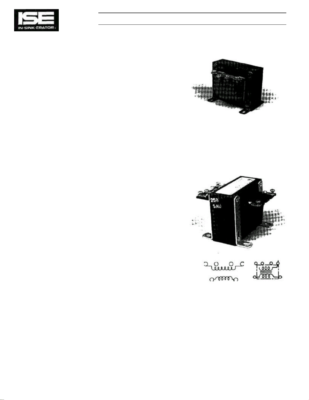
Transformer
The transformer steps down the higher voltage from the power
line to a relatively low 115 volts (24 volts for some models).
This lower voltage is used for control purposes to power the
controlling components, which may include a reverser/timer, a
latch relay coil, a contactor coil, a solenoid valve, a solenoid
valve timer, a restart delay timer, a timer relay coil, a control
circuit board, and an auto shutoff timer.
Line voltage is applied to the primary winding (the top winding
of the transformer as shown on the wiring diagram), and the
control voltage (115 or 24 volts) is taken from the secondary
winding (the bottom winding). The transformer has several
different input connections so that it can be used with different
line voltages.
Figure 7-1. Transformer.
7-1
Page 24
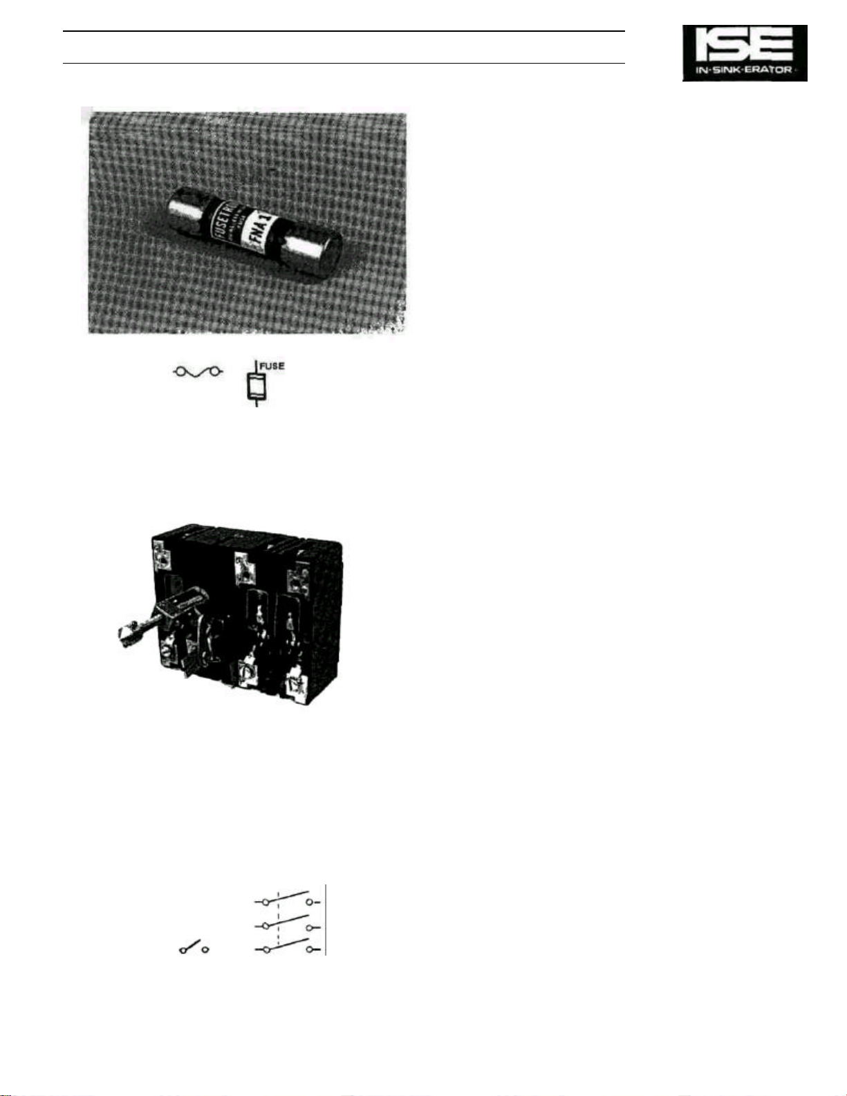
Figure
7-2
. Fuse.
SECTION 7 COMPONENT DESCRIPTION (Cont'd)
Fuse
The fuse, designated F1 on the wiring diagrams in this
manual, provides circuit protection in the event of a
short circuit or other electrical problem in the control
center. If too much current is used by the any
component in the control center, the fuse will blow,
opening the circuit. This fuse does not protect the
disposer motor from excessive current; the disposer
motor is protected by the circuit breaker or fuse in the
line that supplies power to it or by the overload
protector or the disposer motor.
On the wiring diagrams Inside the enclosure door,
some models designate the fuse by Its F1 reference
designation;
other models designate It only by its fuse type, e.g.
FNA 1 or FHA 2.
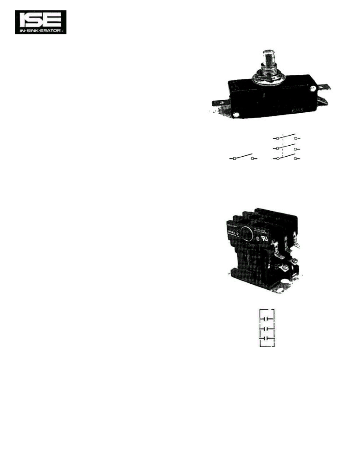
Door Interlock Switch (Line Disconnect)
NOTE
The door interlock switch is a safety device that
combines a disconnect switch with a mechanical door
latch. They are connected together by an "operating
rod" that is fastened to the interlock switch. The door
interlock switch must be turned off to open the control
center door. Turning the switch off disconnects the
power line from the disposer motor and from the
transformer that supplies power to the control circuits
in the control center. This is done as a safety
precaution. However, line voltage is still present on the
line terminals of the door interlock switch.
Figure 7-3. Door Interlock Switch.
7-2
Page 25
Disconnect Switch
COMPONENT DESCRIPTION (Cont'd) SECTION 7
Control centers that do not have a door interlock switch have
one or two disconnect switches mounted at the top of the
control center enclosure. The switch (es) are positioned so that
when the control center door is closed, the switch plunger(s)
are pushed in, closing the switch contacts. Disconnect switch
contacts are wired in series. When the control center door is
opened, the switch contacts open and the control voltage is
turned off, either directly by the disconnect switch or indirectly
by a disconnect relay on units so equipped. This turns off line
voltage to the disposer control center (for units with two
disconnect switches, only one disconnect switch has to be
open to disconnect the control voltage). However, line voltage
is still present at the power line terminals of some components
(refer to the appropriate wiring diagram to determine which
terminals remain live for any particular model).
Disconnect Relay (Line Disconnect)
Some models of disposer control center have a disconnect
relay that works in conjunction with disconnect switches. The
disconnect relay supplies line power to the disposer control
center. The disconnect relay coil is powered directly from the
power lines (line voltage). Power to the disconnect relay coil is
controlled by the disconnect switches. If either switch opens
(the control center door is opened), the disconnect relay coil is
turned off. This opens the relay, disconnecting line power to the
disposer control center. However, line voltage is still present on
the power line terminals of the disconnect relay even when the
contactor is open.
Figure 7-4. Disconnect Switch.
Figure 7-5. Disconnect Relay.
7-3
Page 26
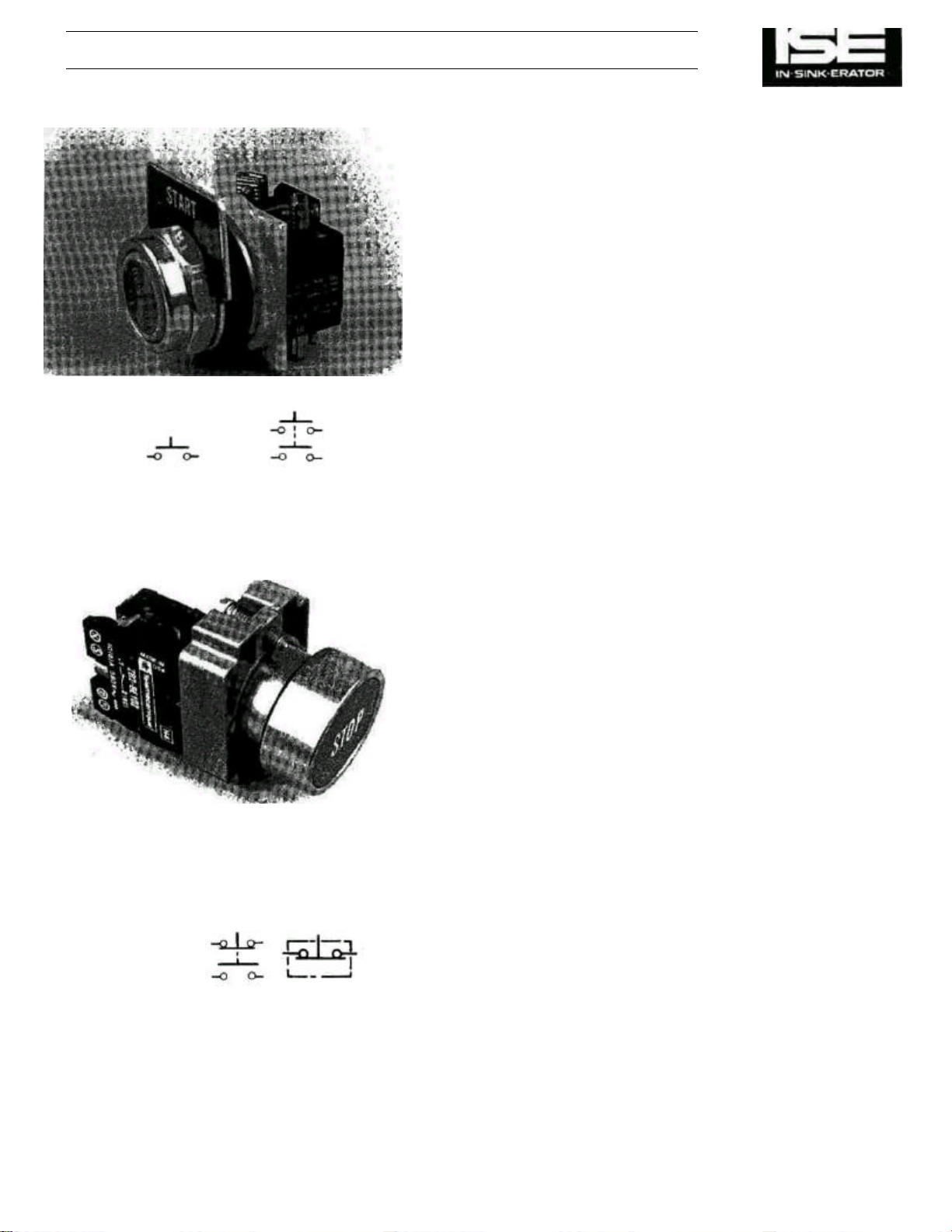
Figure
7-6.
START Switch.
SECTION 7 COMPONENT DESCRIPTION (Cont'd)
START Switch
The START switch has one or more sets of contacts, depending upon
the model. When the START switch is pressed, all the contacts close.
Depending upon the model, the contacts send power to different
devices such as the contactor coil, the solenoid valve, the control
circuit board, and the auto shutoff timer. All functions required to start
the disposer are switched by the START switch contacts.
For all models, the START and STOP switches are each composed of a mechanical pushbutton connected to one or two
detachable sets of electrical contacts that open and close as
the pushbutton moves In and out. However, for the operational
description, the STOP and START switches are treated as
single components rather than as assemblies.
STOP Switch
The STOP switch has one or more sets of contacts, depending
upon the model. When the STOP switch is pressed the
contacts open or close, depending upon whether they are
normally open. or normally closed. One set of contacts opens
to interrupt power to the contactor coil (either directly or via the
control circuit board). Other contacts close to activate the
alternator/timer, latch relay, or the restart delay timer.
NOTE
NOTE
The start and stop switches are momentary contact pushbutton switches. Once pressed in, they will return to their original
position when released.
Figure 7-7. STOP Switch.
7-4
Page 27
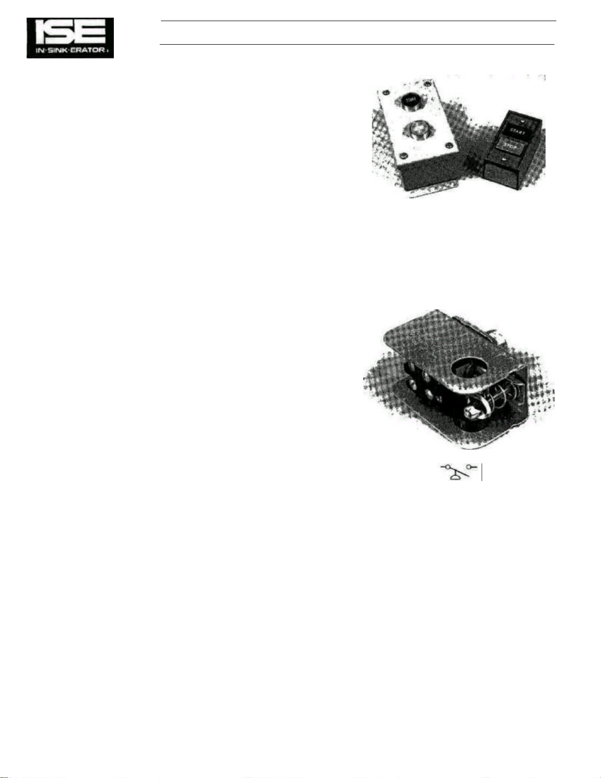
Remote Control Station
Figure
7-8.
Remote Control Station.
COMPONENT DESCRIPTION (Cont'd) SECTION 7
This is a START switch and a STOP switch that can be mounted at a
distance from the control center, and are the same type and design of
those on the control center. The remote START switch contacts are
connected in parallel with the control center START switch contacts.
The remote STOP switch contacts are connected in series or parallel
with the control center STOP switch contacts, depending upon the
model. (Refer to the appropriate wiring diagram.)
Pressure Switch
The pressure switch prevents the disposer motor from operating if the
water pressure falls below approximately 15 p.s.i. If pressure drops
below this point, the pressure switch opens, interrupting power to the
component parts and shuts down the disposer. The START switch
must be pressed to restart the disposer. The pressure switch acts in
the same manner as a STOP switch.
Figure 7-9. Pressure Switch.
7-5
Page 28
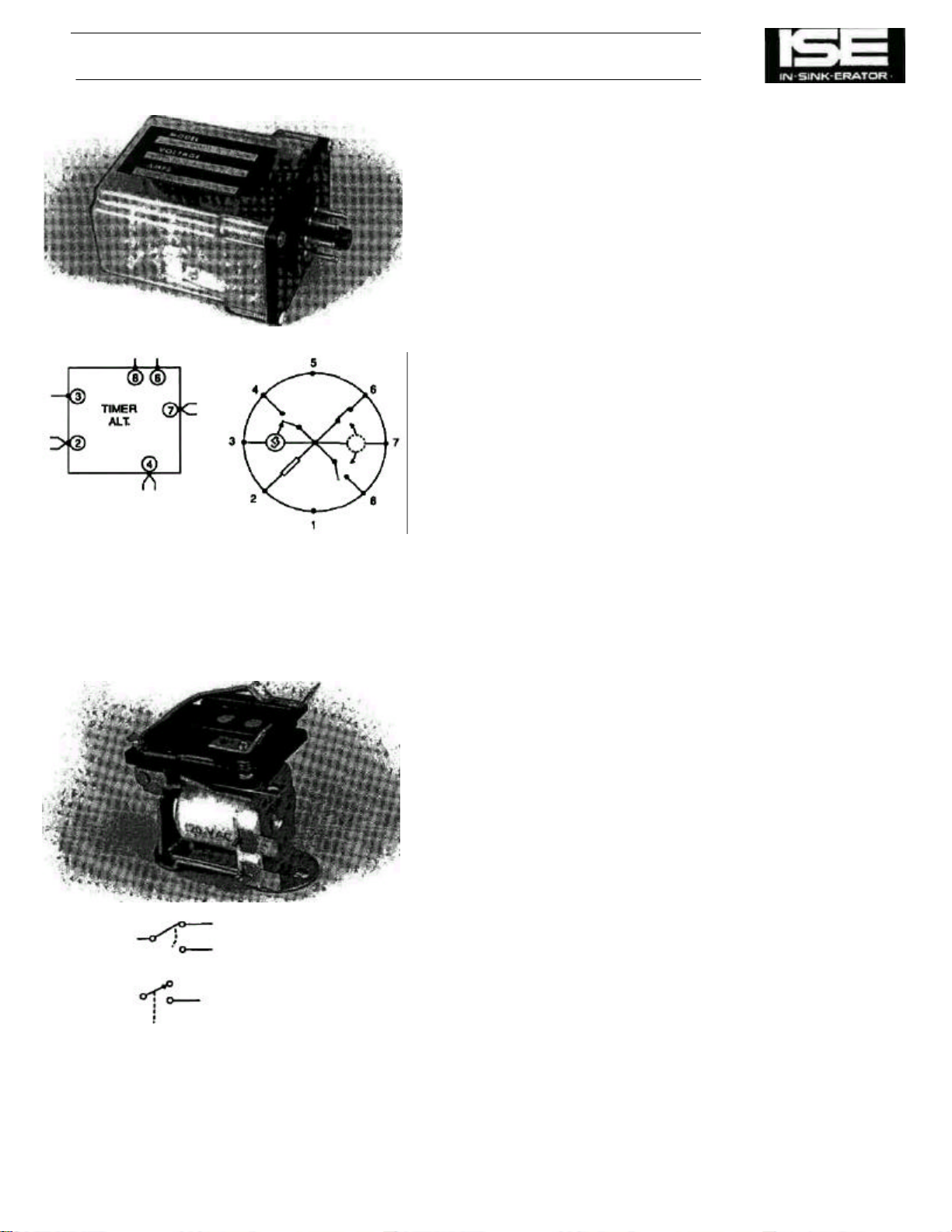
Reverser/Timer
SECTION 7 COMPONENT DESCRIPTION (Cont'd)
The reverser/timer performs two different functions for the
disposer control center. It switches between the F and the R
contactor coils with every START/STOP cycle. This provides
the automatic reversing action for the disposer motor. It also
controls the water flow timing cycle. When the STOP switch is
pressed the reverser/timer begins the 5-minute water flow
timing cycle; it maintains power to the solenoid valve until the
cycle ends. Terminal 2 is the power input, terminal 7 is ground
(common), terminal 4 is the output that drives the solenoid
valve, and terminal 3 senses when each START/ STOP cycle
begins and ends. Terminals 6 and 8 connect to the F (forward)
and R (reverse) contactor coils respectively. Note that when the
START switch is pressed, the reverser/ timer connects the F or
R contactor coil internally to pin 7 to turn the contactor coil on.
Latch Relay (Reversing Relay)
The latch relay performs the automatic reversing of the disposer motor. This relay toggles ("flip-flops") or switches
between its two sets of contacts once per START/STOP cycle.
In one position, the latch relay directs voltage to the F (forward)
contactor coil, causing the disposer motor to run in the forward
direction. In the other position, the latch relay directs voltage to
the R (reverse) contactor coil, causing the motor to run in the
Figure 7-10. Reverser/Timer and Socket.
reverse direction. The latch relay changes position every time
the STOP switch is pressed.
Figure 7-11. Latch Relay.
7-6
Page 29
COMPONENT DESCRIPTION (Cont'd) SECTION 7
Alternator Switch (Reversing)
The alternator switch provides auto-reversing action for the
disposer motor by alternately selecting between its two outputs every START/STOP cycle. The alternator switch is mechanically linked with the STOP switch so that every time the
STOP switch is pressed, the alternator switch changes from
one output to the other. One output is connected to the F
contactor coil; the other is connected to the R contactor coil.
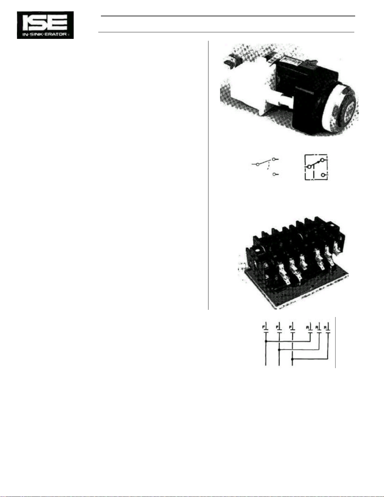
Contactors (Reversing Contactors)
Two contactors, F (forward) and R (reverse), direct line
voltage to the disposer motor. They are either mounted separately or on a mutual mounting plate. One connects the
disposer motor windings to run the disposer in the forward
direction. The other connects them to run in the reverse direction. Depending upon the model of disposer control center,
selection of the contactors is controlled by the reverser/ timer,
reversing switch, latch relay, or control circuit board. This
description does not include the auxiliary contacts or auxiliary
contact microswitches mounted to the reversing contactor.
When power is applied to one of the contactor coils, all of the
contacts associated with that coil close. They open again
when power is removed from the coil. Note that only one
contactor, F or R, can be energized at a time. All the F
contacts shown on the wiring diagram close when the F contactor coil is energized. All the R contacts close when the R
coil is energized. When the contactor pulls down engaging the
contacts carrying power to the motor, it also activates the
auxiliary contacts or auxiliary contact microswitches.
Since the application of the contacts differs from one model of
disposer control center to the next, it is necessary to refer to
the wiring diagram for each model to determine their
functions.
Figure 7-12. Alternator Switch (Is fastened to the
STOP switch).
Figure 7-13. Contactors.
7-7
Page 30
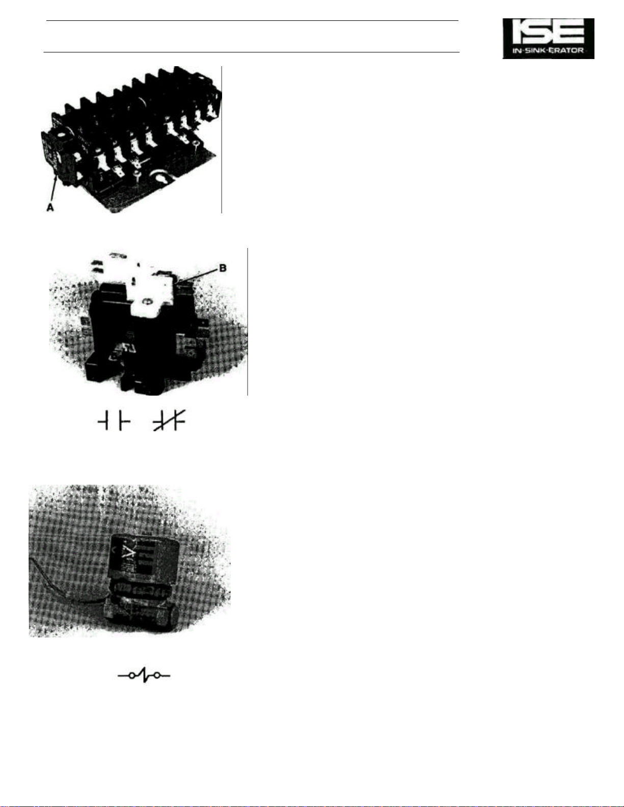
Figure
7-14.
Auxiliary Contacts.
Auxiliary Contacts
SECTION 7 COMPONENT DESCRIPTION (Cont'd)
Auxiliary contacts are additional sets of contacts (block or
microswitches) mounted to and are activated in unison with the
mechanical action of the reversing contactors.
Auxiliary contact blocks are mounted to the end of the reversing
contactor. See Fig. 7-14 (A).
Auxiliary contact microswitches are mounted to the top of the
reversing contactor. See Fig. 7-14 (B).
Auxiliary contacts may contain one or two sets of contacts which may
have any combination of N.O. and/or N.C.
They are used in the control circuit to:
• Bypass the start button (switch) after the unit is started and the start
button is released, maintaining power to the control circuit.
• Activate power to the "F" or "R" coil in the reversing contactor.
• Engage the time delay relay controlling the solenoid
valve.
• "Lockout" the reversing contactor coil not engaged preventing it
from being activated.
• Maintain power to the time delay relay holding the solenoid valve
engaged after the stop button is pressed and the disposer motor
stops.
The model of the control center determines the type, the number of
and the function of the auxiliary contacts. Review the respective wiring
diagram.
Solenoid Valve
The solenoid valve is an electrically-controlled water valve. The
valve opens when power is applied to the solenoid valve coil,
allowing water to flow to the disposer. When power to the coil is
removed, the valve shuts off the water flow. The solenoid valve
is powered by the transformer in the disposer control center,
and is controlled by the reverser/timer, the time delay relay, or
a printed circuit board.
The solenoid valve must be installed with its arrow pointing
downstream or erratic water flow will occur.
Figure 7-15. Solenoid Valve.
7-8
Page 31

COMPONENT DESCRIPTION (Cont'd) SECTION 7
Solenoid Valve Timer (Time Delay Relay)
The solenoid valve timer is a solid state electronic device.
After the STOP switch is pressed the disposer motor stops
but, the solenoid valve timer supplies power to the solenoid
valve for a defined time (which can be adjusted by a potentiometer) to provide water to the disposer which helps reduce
drain clogging. When the water flow timing cycle ends, the
solenoid valve timer removes power from the solenoid valve,
shutting off the flow of water.
Potentiometer
The potentiometer is a device with an adjustable screw or
stem used to control the time-out of the time delay relay. It is
connected directly to the time delay relay and is adjustable
from 0 to 5 or 10 minutes depending on the model. Using a
small flat blade screwdriver and turning the screw fully
clockwise, will set the time-out to maximum.
Restart Delay Timer
The disposer motor should not be subjected to rapid reversals
in direction which could occur if the unit were turned on and
off rapidly a number of times, which causes' motor burnout. To
prevent this, the restart delay timer stops the disposer from
restarting within 5 seconds after it is turned off. The restart
delay timer is a non-adjustable electronic timer. When the
STOP switch is pressed, one pair of STOP switch contacts
(as shown on the wiring diagram) signals the restart delay
timer to begin the restart timeout period. When this happens,
the restart delay timer applies power to the timer relay coil.
The timer relay contacts open, preventing power from
reaching either contactor; this prevents the unit from being
started. When the restart timeout period ends, the restart
delay timer allows normal operation again.
Figure 7-16. Solenoid Valve Timer and Potentiometer.
Figure 7-17. Restart Delay Timer.
7-9
Page 32

Figure
7-18.
Timer Relay.
SECTION 7 COMPONENT DESCRIPTION (Cont'd)
Timer Relay
This time relay has several sets of contacts which can N.O., N.C., or
both. The contacts open or close when the coil in the relay is
activated.
This relay works in conjunction with the restart delay timer to
provide restart delay protection control for the disposer motor.
When the STOP switch is pressed, the bottom STOP switch
contacts close, supplying power to the restart delay timer and
the timer relay coil (TR). The energized coil closes the TR1
contacts, supplying power to terminal 2 of the restart delay
timer. This signals the restart delay timer to maintain power to
the timer relay coil (via terminal 1) until the restart timeout
period expires. During the restart timeout period, the TR2
contacts open to prevent current from flowing through the
reversing contactor coils, thus preventing operation of the
disposer motor. When the restart timeout period expires, the
restart delay timer removes the power from terminal 1. The TR
relay then returns to normal, opening the TR1 contacts and
closing the TR2 contacts. When this happens, the disposer
can be started again.
7-10
Page 33

Control Circuit Board
Figure
7-19.
Control Circuit Board.
COMPONENT DESCRIPTION (Cont'd) SECTION 7
NOTE
This electronic circuit board contains the larger and bulkier time
delay relays, relays potentiometer and alternator found is earlier
model control centers. It is a totally self-contained unit and is
non-repairable.
This device controls the reversing contactor coils, the water flow
tinning cycle, the restart timeout period, and the auto shutoff
function for the control center. It also controls the auto reversing
for the disposer motor with every START/ STOP cycle.
Power from the transformer is supplied to the circuit board via
terminals 2 and 4. Terminal 4 is the common, or chassis
ground. Terminal 7 of the control circuit board is the START/
STOP switching input. When the input goes high (on), the
control circuit board starts the disposer motor and turns on the
solenoid valve to allow water to flow to the disposer. When the
input goes low (off), the control board stops the disposer,
begins the water flow timing cycle and begins the restart
timeout period.
Terminal 11 is the output line to the F (forward) contactor coil.
(Power is supplied to the F contactor coil via terminal 11 and
chassis ground, terminal 4.) This line is used to close the F
contactor, which runs the disposer motor in the forward
direction.
Terminal 12 is the output line to the R (reverse) contactor coil.
(Power is supplied to the R contactor coil via terminal 12 and
chassis ground, terminal 4.) This line is used to close the R
contactor, which runs the disposer motor in the reverse
direction.
Terminal 13 is the output line to the solenoid valve. (Power is
supplied to the solenoid valve via terminal 13 and chassis
ground, terminal 4.) This line is used to turn on the solenoid
valve, which allows water to flow to the disposer.
Flow Control Valve
The flow control valve is installed in the water supply line
between the solenoid valve and the disposer. When the solenoid valve is open, the flow control valve regulates the flow of
water to the disposer. By providing optimum water flow, it
prevents excessive water consumption while allowing adequate
water for proper disposer operation. The flow control valve
requires no electric power.
Disposer application requires a properly sized valve (3,5 or 10
G.P.M.) 3/4" N.P.T. It must be installed with the arrow on the
valve pointing downstream or the diaphragm in the valve will not
control proper water flow.
Figure 7-20. Flow Control Valve.
7-11
Page 34

SECTION 7 COMPONENT DESCRIPTION (Cont'd)
Auto Shutoff Timer
The auto shutoff timer is an adjustable electronic device that is
electrically the same as the solenoid valve timer. The auto
shutoff timer is connected so that once the disposer motor is
started, it will shut off automatically after a defined period of
time (the period may or may not be adjusted by a potentiometer). However, the motor will also stop at any time if the
STOP switch is pressed.
Figure 7-21. Auto Shutoff Timer.
7-12
Page 35

COMPONENT DESCRIPTION (Cont'd) SECTION 7
Pressure Switch
A pressure switch is an electrical switch whose contacts are activated
by water pressure.
A water line connected to the water fitting allows water pressure to
press against a diaphragm. This action overcomes the spring
tensioned disk behind the diaphragm, allowing the disk to make and
activate the switch contacts.
The pressure switch assures water flow to the disposer when it is
running. Whenever the water pressure diminishes, it is sensed by the
pressure switch and its contacts open shutting down the operation.
Pressure switches in control centers are preadjusted to close its
contacts at a water pressure of 15 P.S.I, or more.
A momentary pressure drop can cause the switch to drop out,
opening the circuit.
Figure 7-22. Pressure Switch.
7-13
Page 36

COMPONENT LOCATION SECTION 8
GENERAL
This section shows the location of each component for each standard
model of disposer control center. A separate photograph is provided
for each model.
CC-101 A
Figure 8-1. Model CC-101 A Disposer Control Center, Component Location Diagram. PARTS
LEGEND
Item No. Description
1 START Switch
2 STOP Switch
3 Disconnect Handle
4 Transformer
5 Fuse
6 Contactor, Reversing
7 Alternator-Timer
8 Water Solenoid Valve
9 Pressure Switch
10 Flow Control Valve
11 Operating Rod
12 Auxiliary Contacts
13 Line Disconnect Switch
8-1
Page 37

SECTION 8 COMPONENT LOCATION (Cont'd)
C-101 B
Figure 8-2. Model CC-101B Disposer Control Center, Component Location Diagram.
PARTS LEGEND
Item No. Description
1 START Switch
2 STOP Switch
3 Disconnect Handle
4 Transformer
5 Fuse
6 Contactor, Reversing
7 Latch Relay (Alternator)
8 Potentiometer
9 Line Disconnect Switch
10 Solenoid Valve
11 Pressure Switch
12 Flow Control Valve
13 Operating Rod
14 Auxiliary Contacts
15 Time Delay Relay
8-2
Page 38

COMPONENT LOCATION (Cont'd) SECTION 8
CC-101 C
Figure 8-3. Model CC-101C Disposer Control Center, Component Location Diagram.
PARTS LEGEND
Item No. Description
1 STOP Switch (w/Reverser Switch attached)
2 START Switch
3 Disconnect Switch
4 Transformer
5 Fuse
6 Contactor, Disconnect
7 Time Delay Relay
8 Potentiometer
9 Reversing Contactor
10 Auxiliary Contacts
8-3
Page 39

PARTS LEGEND
SECTION 8 COMPONENT LOCATION (Cont'd)
CC-101 D
Figure 8-4. Model CC-101D Disposer Control Center, Component Location Diagram.
Item No. Description
1 START Switch
2 STOP Switch (w/Reverser Switch attached)
3 Disconnect Switch
4 Transformer
5 Fuse
6 Auxiliary Contact Block
7 Time Delay Relay
8 Potentiometer
9 Disconnect Contactor
10 Contactor, Reversing
8-4
Page 40

COMPONENT LOCATION (Cont'd) SECTION 8
CC-101 E
Figure 8-5. Model CC-101 E Disposer Control Center, Component Location Diagram.
PARTS LEGEND
Item No. Description
1 START Switch
2 STOP Switch (w/Reverser Switch attached)
3 Disconnect Switch
4 Transformer
5 Fuse
6 Contactor, Reversing
7 Timer-On Delay
8 Time Delay Relay
9 Potentiometer
10 Relay
11 Auxiliary Contacts
12 Water Solenoid Valve (Not Shown)
Page 41

SECTION
8 COMPONENT LOCATION (Cont'd)
CC-101 G
8-6
Figure 8-6. Model CC-101G Disposer Control Center, Component Location Diagram.
PARTS LEGEND
Item No. Description
1 START Switch
2 STOP Switch
3 Disconnect Switch
4 Transformer
5 Fuse
6 Auxiliary Contact Block
7 Circuit Board
8 Terminal Block
9 Contactor, Reversing
10 Water Solenoid Valve (Not Shown)
Page 42

OPERATING SEQUENCE SECTION 9
GENERAL
This section describes the operating sequence of the IN-SINKERATOR Commercial Disposer Control Center and illustrates
the electrical operation with diagrams. The description is
written to apply to all control centers, with differences between
models noted as necessary. Differences between models are
best noted by referring to the schematic wiring diagrams that
are mounted on the inside of the door in each control center
enclosure.
NOTE
All models have some type of interlock or disconnect switch
that prevents operation of the disposer when the control center door is open.
1. The operator presses the START switch. The START
switch contacts close, supplying power to the F (forward) or R
(reverse) contactor coil. On some models, the power does not
go directly to the contactor coils from the switch, but instead
goes to a control circuit board that determines which contactor
coil will be energized.
Some models have a second set of contacts on the START
switch that supply power to the solenoid valve while the start
switch is pressed. When the START switch is released, power
to the solenoid valve is supplied by the reverser/ timer, the
solenoid valve timer, or the control circuit board, depending
upon the model.
Models equipped with an auto shutoff timer have an additional
pair of contacts on the START switch that signal the auto
shutoff timer to begin timing the auto shutoff cycle. (On all
models the disposer motor stops immediately when the STOP
switch is pressed, regardless of whether the unit has an auto
shutoff timer.)
NOTE
For models that have a pressure switch, the water pressure
must be at least 15 p.s.i. to keep the pressure switch closed or
the disposer motor will not run. If the water pressure Is less
than 15 p.s.i. the pressure switch contacts will open, preventing power from reaching the contactor coil.
NOTE
For the purpose of this description, operation is described with
the F contactor coil selected. However, operation Is the same
when the R coil is selected; the only thing that changes is the
disposer motor's direction of rotation. (The direction reverses
with every START/STOP cycle.) Energizing the F contactor
coil closes all the F contacts shown on the wiring diagram.
Energizing the R contactor coil closes all the R contacts. Only
one contactor can be closed at a time.
2. The energized contactor coil closes the contactor, causing
two things to happen:
a. Power is applied to the disposer motor through the F
contacts.
b. The F contact across the START switch closes, sup-
plying continuous power to the contactor coil. This
keeps the contactor closed after the START switch is
released. (This has the same effect as holding the
START switch in continuously.)
9-1
Page 43

SECTION 9 OPERATING SEQUENCE (Cont'd)
3. Solenoid valve power is maintained by the reverser/ timer,
the solenoid valve timer, or the control circuit board,
depending on the control center model.
This condition continues until the operator presses the STOP
switch.
4. The operator presses the STOP switch. The STOP switch
contacts open, interrupting power to the F contactor coil.
Some models have a second set of contacts on the STOP
switch that are used to supply power to the latch relay coil to
make it change from one state to another, or to signal a restart
delay timer to begin the restart timeout period.
On some models a reverser switch is mechanically linked to
the STOP switch. The reverser switch is used to alternately
select the F (forward) or R (reverse) contactor coil, which
determines the disposer motor's direction of rotation. The two
output terminals of the reverser switch are connected to the F
and R contactor coils. Every time the STOP switch is pressed,
the reverser switch changes from one output terminal to the
other.
Models with a restart delay timer have an additional set of
contacts on the stop switch that signal the restart delay timer to
begin the restart timeout period.
5. The F contactor coil releases (opens) the F contacts,
turning off power to the disposer motor.
6. The water flow timing cycle begins. During the water flow
timing cycle, solenoid valve power is maintained by the
reverser/timer, the solenoid valve timer, or the control
circuit board, depending on the control center model.
7. When the water flow timing cycle ends, the reverser/ timer,
the solenoid valve timer, or the control circuit board
removes power from the solenoid valve, shutting off the
flow of water to the disposer.
8. Operation is the same for the next START/STOP cycle,
except that the R contactor is energized instead of the F
contactor.
REVERSING
All CC-101 Series Commercial Disposer Control Centers
perform automatic reversing of the disposer motor with each
START/STOP cycle. The disposer operates effectively in either
direction, and the reversing action doubles the life of the
shredders in the disposer. The reversing can be accomplished
with a reverser/timer, a latch relay, an reverser switch, or a
control circuit board, depending on the control center model.
Although the components are different, they all perform
disposer motor reversing by changing state every
START/STOP cycle. Descriptions of these components are
provided in the Component Function section of this manual.
9-2
Page 44

COMPONENT TESTING AND REPLACEMENT SECTION 10
GENERAL
This section provides information on testing and replacement of all
the disposer control center components, including the solenoid valve
and the pressure switch. Component variations among the different
disposer control center models are noted in the procedures when
applicable. To simplify testing, these procedures test the components
in the circuit whenever possible. This eliminates having to remove
each component for testing.
Many of the test procedures require a voltmeter. Either a volt-ohm
meter (VOM), a digital multimeter (DMM), or a vacuum-tube
voltmeter (VTVM) may be used. All measurements are in AC volts
unless otherwise noted. Continuity testing (with ohm meter) can be
used - with line voltage off - to test components. Care must be taken
to set the meter to the correct setting (voltage or ohms) and range
BEFORE each measurement is taken. Failure to do so may destroy
the meter. (The expected voltage or resistance reading is listed in
each step where a voltage measurement is taken.) Also, be sure to
plug the meter test leads into their correct sockets on the meter; on
many meters, the lead sockets used for resistance measurements
are separate from the sockets used for voltage measurements.
WARNING
TESTING OF COMPONENTS IN THE CIRCUIT WITH POWER APPLIED
EXPOSES THE REPAIR TECHNICIAN TO DANGEROUS VOLTAGES. BE
VERY CAREFUL NOT TO TOUCH ANY WIRES OR TERMINALS THAT
MAY BE CARRYING HIGH VOLTAGE.
Each wire in the disposer control center is identified by a numbered
tag on the wire. (Red wires carry control voltage, black wires carry
line voltage.) The same numbers are shown on the wiring diagram.
Component terminal numbers provided in this section, unless
otherwise noted, refer to the identification number of the wire
connecting to a component terminal.
Many tests require that the door interlock switch or disconnect switch
(es) be defeated. Appropriate defeat procedures are provided at the
beginning of this section.
DOOR INTERLOCK SWITCH DEFEAT PROCEDURE,
MODELS CC-101A AND CC-101B
Perform this procedure when it is necessary to test any component
with the enclosure door open.
WARNING
THIS PROCEDURE DEFEATS THE DOOR INTERLOCK SWITCH
AND PLACES LINE VOLTAGES AND CONTROL VOLTAGES ON
NUMEROUS TERMINALS INSIDE THE DISPOSER CONTROL
CENTER. BE VERY CAREFUL NOT TO TOUCH ANY WIRES OR
TERMINALS INSIDE THE DISPOSER CONTROL CENTER
ENCLOSURE.
Figure 10-1. Defeating Door Interlock Switch.
10-1
Page 45

SECTION 10
COMPONENT TESTING AND
REPLACEMENT (Cont'd)
1. Turn off power line to disposer control center. Check
power inside control center to ensure that it is off.
2. Grasp shaft of door interlock switch with large pliers and
turn shaft counterclockwise until switch snaps into ON
position (See Figure 10-1).
3. When testing is complete, switch must be returned to
OFF position before enclosure door can be closed.
DISCONNECT SWITCH DEFEAT PROCEDURE,
MODELS CC-101C THROUGH CC-101G
Perform this procedure when it is necessary to test any
component with the enclosure door open.
THIS PROCEDURE DEFEATS THE DISCONNECT SWITCH (ES)
AND PLACES LINE VOLTAGES AND CONTROL VOLTAGES ON
NUMEROUS TERMINALS INSIDE THE DISPOSER CONTROL
CENTER. BE VERY CAREFUL NOT TO TOUCH ANY WIRES OR
TERMINALS INSIDE THE DISPOSER CONTROL CENTER
ENCLOSURE.
1. Turn off power line to disposer control center.
2. Place a small piece of plywood over plunger(s) of disconnect switch (es). Clamp wood to lip of enclosure,
holding the switch plunger(s) in (closed) position. (See
Figure 10-2). Ensure that clamp does not touch any wires
or connectors inside the enclosure.
Model CC-101G Control Centers have normally closed
switches that can be bypassed by moving switch leads from
the normally closed (N.C.) to the normally open (N.O.) terminal.
3. When testing is complete, be sure to remove wood and
clamp, or restore switch to the correct configuration.
WARNING
NOTE
Figure 10-2. Defeating Disconnect Switch.
10-2
Page 46

COMPONENT TESTING AND
SECTION
10
Figure
10-4.
Measuring Fuse Voltage.
REPLACEMENT (Cont'd)
TRANSFORMER TEST PROCEDURE. ALL
MODELS
1. Turn off power line to disposer control center. Check inside
enclosure to ensure that power is off.
2. Perform door interlock switch defeat procedure or disconnect switch defeat procedure as appropriate.
3. Turn on power line to disposer control center.
4. Measure voltage between two power line (black) wires
connected to primary winding terminals of transformer.
(See Figure 10-3.) Voltage should be same as power line
voltage. If voltage is 0, either power line is off or door
interlock/disconnect switch was not defeated properly.
Correct these conditions before proceeding to next step.
5. Measure voltage between two red wires on secondary
winding terminals of transformer. Voltage should be 115
volts (CC-101G 24 volts).
TRANSFORMER REPLACEMENT PROCEDURE, ALL
MODELS
1. Turn off power line to disposer control center.
2. Note location of all wires connected to transformer.
Disconnect wires.
3. Remove screws securing transformer to panel and remove
transformer.
4. Align replacement transformer with mounting holes and
secure to panel with screws.
5. Connect wires to proper transformer terminals. FUSE
Figure 10-3. Measuring Transformer Input
Voltage.
TEST PROCEDURE, ALL MODELS
1. Turn off power line to disposer control center.
2. Perform door interlock switch defeat procedure or disconnect switch defeat procedure as appropriate.
3. Turn on power line to disposer control center.
4. Measure voltage between chassis ground (any un-painted
metal surface on the disposer control center housing) and
one end of fuse, then between ground and other end of
fuse. (See Figure 10-4). Voltage should be 115 volts (24
volts for CC-101G) on either end of fuse. If one end is 0
volts, fuse is blown and should be replaced.
10-3
Page 47

SECTION 10
(Model CC-101A) (Model CC-101 B)
Figure 10-5. Measuring Voltage Across Door
Interlock Switch.
COMPONENT TESTING AND
REPLACEMENT (Cont'd)
FUSE REPLACEMENT PROCEDURE,
ALL MODELS
1. Turn off power line to disposer control center. Check for power
inside enclosure to ensure that power is off.
2. Remove fuse from spring-loaded holder using a cartridge
fuse puller (or equivalent).
3. Push replacement fuse into holder. DOOR INTERLOCK
SWITCH TEST PROCEDURE
1. Turn on power to disposer control center.
2. Measure voltage across one pair of disconnect switch
terminals. (See Figure 10-5). Voltage should be same as
line voltage.
3. Use pliers to carefully rotate door interlock switch to ON
position. Voltage should go to 0 volts.
4. Repeat steps 2 and 3 for other sets of contacts on door
interlock switch.
DOOR INTERLOCK SWITCH REPLACEMENT
PROCEDURE
1. Turn off power line to disposer control center. Check to
ensure that power is off in the enclosure.
2. Note location of wires connected to door interlock switch.
Disconnect wires.
3. Remove screws securing door interlock switch to panel.
Remove door interlock switch.
4. Put replacement switch in position on panel and secure
with screws.
5. Connect wires to proper terminals on replacement switch.
10-4
DISCONNECT SWITCH TEST PROCEDURE,
MODEL CC-101A AND CC-101B
1. Turn on power line to disposer control center.
2. Measure voltage between disconnect switch terminals. Voltage
should be 115, 208, 230, or 460 volts, depending on model.
Page 48

COMPONENT TESTING AND
REPLACEMENT (Cont'd)
DISCONNECT SWITCH TEST PROCEDURE, MODEL
CC-101C, MODEL CC-101D AND CC-101E
1. Turn on power line to disposer control center.
2. Measure voltage between terminals of disconnect switch on
right-side of enclosure while holding down plunger of leftside switch. (See Figure 10-6.) Voltage should be 24 or 115
volts, depending on model.
3. Measure voltage between terminals of left-side disconnect
switch while holding down plunger of right-side disconnect
switch. Voltage reading should be 24 or 115 volts,
depending on model.
DISCONNECT SWITCH TEST PROCEDURE,
MODEL CC-101G
1. Turn on power line to disposer control center.
2. Measure voltage between terminals of disconnect switch.
With door open (disconnect switch plunger should be out),
voltage should be 24 volts.
3. Push switch plunger in. Voltage should go to 0 volts.
DISCONNECT SWITCH REPLACEMENT
PROCEDURE, SNAP-MOUNT SWITCH
SECTION 10
Figure 10-6. Measuring Voltage Across
Disconnect Switch.
1. Turn OFF power to disposer control center.
2. Note location of wires connected to disconnect switch.
Disconnect wires.
3. Use a razor blade or hobby knife to carefully cut away any
adhesive securing disconnect switch to mounting hole.
4. Squeeze together the retaining clips on each side of switch
to allow switch to be pulled out through mounting hole.
Remove switch from mounting hole.
5. Put replacement switch in mounting hole and push switch
into hole until it snaps into place. Secure switch with clear
silicone-type adhesive such as R.T.V. or G.E. Silicone
adhesive.
6. Connect wires to proper terminals on disconnect switch.
DISCONNECT SWITCH REPLACEMENT
PROCEDURE, THREAD-MOUNT SWITCH
1. Make sure power is off to disposer control center.
2. Note location of wires connected to disconnect switch.
Disconnect wires.
3. Remove nut and lock washer securing switch to enclosure.
Remove switch from enclosure.
4. Position replacement switch in mounting hole and secure
with nut and lock washer.
10-5
Page 49

SECTION 10
COMPONENT TESTING AND
REPLACEMENT (Cont'd)
Figure 10-7. Measuring Voltage At Disconnect
Relay.
5. Connect wires to proper terminals on disconnect switch.
DISCONNECT RELAY TEST PROCEDURE
1. Turn on power to disposer control center.
2. Perform disconnect switch defeat procedure. Disconnect
relay should close when both disconnect switch plungers
are pushed down.
3. Measure voltage between 1L1 (line) and L1 (load) terminals of disconnect relay. (See Figure 10-7). Voltage
reading should be 0 volts.
• Measure voltage between any 2 line terminals. Voltage
reading should be line voltage.
• Repeat step 3 for terminals 1L2 and L2, and for terminals
1L3 and L3.
DISCONNECT RELAY REPLACEMENT
PROCEDURE, MODELS CC-101C AND CC-101D
1. Turn off power to disposer control center.
2. Note location of wires connected to disconnect relay.
Disconnect wires.
3. Remove screws securing disconnect relay to panel.
Remove disconnect relay.
4. Put replacement disconnect relay in position on panel and
secure with screws.
5. Connect wires to proper terminals on disconnect relay.
Figure 10-8. Measuring Voltage Across START
Switch.
10-6
START SWITCH TEST PROCEDURE,
MODEL CC-101A
WARNING
WHEN PERFORMING THIS TEST, THE DISPOSER MOTOR WILL
RUN. MAKE SURE NO PERSON IS WORKING NEAR THE
DISPOSER WHEN THIS TEST IS PERFORMED.
1. Turn off power line to disposer control center.
2. Perform door interlock defeat procedure.
3. Turn on power line to disposer control center.
4. Measure voltage between switch terminals 4 and 7. (See
Figure 10-8.) Voltage should be 120 volts.
5. Press START switch. Measure voltage between switch
terminals 4 and 7. Voltage should be 0 volts.
6. Press STOP switch and repeat steps 4 and 5 for terminals
3 and 5.
7. Press STOP switch when finished with test procedure.
Page 50

COMPONENT TESTING AND
REPLACEMENT (Cont'd)
START SWITCH TEST PROCEDURE, MODEL
CC-101B
WARNING
WHEN PERFORMING THIS TEST, THE DISPOSER MOTOR
WILL RUN. MAKE SURE NO PERSON IS WORKING NEAR
THE DISPOSER WHEN THIS TEST IS PERFORMED.
1. Turn off power line to disposer control center.
2. Perform door interlock defeat procedure.
3. Turn on power line to disposer control center.
4. Measure voltage between switch terminals 3 and 11.
Voltage should be 120 volts.
5. Press START switch. Measure voltage between switch
terminals 3 and 11. Voltage should be 0 volts.
6. Press STOP switch and repeat steps 4 and 5 for terminals
3 and 5.
7. Press STOP switch when finished with test procedure.
START SWITCH TEST PROCEDURE,
MODELS CC-101C AND CC-101D
SECTION 10
WARNING
WHEN PERFORMING THIS TEST, THE DISPOSER MOTOR WILL
RUN. MAKE SURE NO PERSON IS WORKING NEAR THE
DISPOSER WHEN THIS TEST IS PERFORMED.
1. Turn off power line to disposer control center.
2. Perform disconnect switch defeat procedure.
3. Turn on power line to disposer control center.
4. Measure voltage between switch terminals 5 and 6. (See
Figure 10-9.) Voltage should be 120 volts.
5. Press START switch. Measure voltage between switch
terminals 5 and 6. Voltage should be 0 volts.
6. Press STOP switch and repeat steps 4 and 5 for terminals
5 and 7.
7. Press STOP switch when finished with test procedure.
START SWITCH TEST PROCEDURE, MODEL
CC-101E
WARNING
WHEN PERFORMING THIS TEST, THE DISPOSER MOTOR WILL
RUN. MAKE SURE NO PERSON IS WORKING NEAR THE
DISPOSER WHEN THIS TEST IS PERFORMED.
1. Turn off power line to disposer control center.
2. Perform disconnect switch defeat procedure.
3. Turn on power line to disposer control center.
Figure 10-9. Measuring Voltage Across START
Switch.
10-7
Page 51

10-8
SECTION 10
COMPONENT TESTING AND
REPLACEMENT (Cont'd)
4. Measure voltage between switch terminals 6 and 7. Voltage
should be 120 volts.
5. Press START switch. Measure voltage between switch terminals
6 and 7. Voltage should go to 0 volts.
6. Press STOP switch when finished with test procedure.
START SWITCH TEST PROCEDURE.
MODEL CC-101G
WARNING
WHEN PERFORMING THIS TEST, THE DISPOSER MOTOR WILL
RUN. MAKE SURE NO PERSON IS WORKING NEAR THE
DISPOSER WHEN THIS TEST IS PERFORMED.
1. Turn off power line to disposer control center.
2. Perform disconnect switch defeat procedure.
3. Turn on power line to disposer control center.
4. Measure voltage between switch terminals 6 and 7. Voltage
should be 24 volts.
5. Press START switch. Voltage should go to 0 volts.
6. Press STOP switch when finished with test procedure.
START SWITCH REPLACEMENT PROCEDURE,
THREADED-COLLAR MOUNT
1. Turn off power line to disposer control center.
2. Note location of wires on switch. Disconnect wires.
3. Unscrew threaded collar securing switch to control center
door. Remove switch.
4. Insert replacement switch in mounting hole in door. Secure switch to door with threaded collar. Be sure letter ing
on switch button is right-side up.
5. Connect wires to proper switch terminals.
START SWITCH REPLACEMENT PROCEDURE,
TWO-SCREW MOUNT
1. Turn off power line to disposer control center.
2. Note location of wires on switch. Disconnect wires.
3. Loosen two screws at rear top and bottom of switch so that rear
section of switch is flush with door.
4. Push front section of switch in (toward rear section), turn it
counterclockwise until it stops (about 1/8 turn). Front and rear
switch sections can now be separated by pulling front section
away from rear section.
5. Remove switch from mounting hole.
6. Position rear section of replacement switch behind mounting
hole. Loosen two screws at rear top and bottom of switch so that
rear section of switch is flush with door.
Page 52

SECTION
10
COMPONENT TESTING AND
REPLACEMENT (Cont'd)
7. Position front section of switch so that lettering on pushbutton is
upright, then turn front section counter-clockwise about 1/8 turn.
Insert front section into rear section as far as it will go, then turn
front section clockwise until it stops (about 1/8 turn).
8. Tighten two screws on rear of switch until switch is secured
tightly in mounting hole. Be sure lettering on pushbutton is still
upright.
9. Connect wires to proper switch terminals.
STOP SWITCH TEST PROCEDURE,
MODEL CC-101A
1. Turn off power line to disposer control center.
2. Open disposer control center door.
3. Perform door interlock switch defeat procedure.
4. Turn on power line to disposer control center.
5. Measure voltage between switch terminals 5 and 9. (See
Figure 10-10.) Voltage should be 0 volts.
6. Press STOP switch. Voltage should go to 120 volts.
7. Measure voltage between switch terminals 2 and 4.
Voltage should be 120 volts.
8. Press STOP switch. Voltage should go to 0 volts.
STOP SWITCH TEST PROCEDURE,
MODEL CC-101B
1. Turn off power line to disposer control center.
2. Open disposer control center door.
3. Perform door interlock switch defeat procedure.
4. Turn on power line to disposer control center.
5. Measure voltage between switch terminals 2 and 3.
Voltage should be 0 volts.
6. Press STOP switch. Voltage should go to 120 volts.
7. Measure voltage between switch terminals 2 and 4.
Voltage should be 120 volts.
8. Press STOP switch. Voltage should go to 0 volts.
Figure 10-10. Measuring STOP Switch Voltage.
STOP SWITCH TEST PROCEDURE,
MODELS CC-101C AND CC-101D
1. Turn off power line to disposer control center.
2. Open control center door.
3. Perform door interlock defeat procedure.
4. Turn on power line to disposer control center.
5. Measure voltage between switch terminals 5 and 3. (See Figure
10-11.) Voltage should be 0 volts.
6. Press STOP switch. Voltage should go to 120 volts.
Figure 10-11. Measuring Voltage Across STOP
Switch.
10-9
Page 53

SECTION 10
COMPONENT TESTING AND
REPLACEMENT (Cont'd)
STOP SWITCH TEST PROCEDURE,
MODEL CC-101E
1. Turn off power line to disposer control center.
2. Perform door interlock defeat procedure.
3. Turn on power line to disposer control center.
4. Measure voltage between switch terminals 5 and 6.
Voltage should be 0 volts.
5. Press STOP switch. Voltage should go to 120 volts.
6. Measure voltage between switch terminals 5 and 11.
Voltage should be 120 volts.
STOP SWITCH TEST PROCEDURE, MODEL
CC-101G
1. Turn off power line to disposer control center.
2. Perform door interlock defeat procedure.
3. Turn on power line to disposer control center.
4. Measure voltage between switch terminals 3 and 6.
Voltage should be 24 volts.
5. Press STOP switch. Voltage should go to 0 volts.
STOP SWITCH REPLACEMENT PROCEDURE,
THREADED-COLLAR MOUNT WITHOUT ATTACHED
REVERSER SWITCH
1. Turn off power line to disposer control center.
2. Note location of wires on switch. Disconnect wires.
3. Unscrew threaded collar securing switch to control center
door. Remove switch.
4. Insert replacement switch in mounting hole in door. Secure switch to door with threaded collar. Be sure lettering
on switch button is right-side up.
5. Connect wires to proper switch terminals.
STOP SWITCH REPLACEMENT PROCEDURE.
THREADED-COLLAR MOUNT WITH ATTACHED
REVERSER SWITCH
1. Turn off power line to disposer control center.
2. Note location of wires on switch. Disconnect wires.
3. Note location of wires connected to reverser switch.
Disconnect wires (reverser switch is mechanically
attached to STOP switch and are replaced as one unit).
4. Unscrew threaded collar securing switch to control center
door. Remove switch.
5. Insert replacement switch in mounting hole in door. Secure switch to door with threaded collar. Be sure letter ing
on switch button is right-side up.
6. Connect wires to proper switch terminals.
10-10
Page 54

COMPONENT TESTING AND
SECTION
10
REPLACEMENT (Cont'd)
STOP SWITCH REPLACEMENT PROCEDURE.
TWO-SCREW MOUNT
1. Turn off power line to disposer control center.
2. Note location of wires on switch. Disconnect wires.
3. Unscrew threaded collar securing switch to control center
door. Remove switch.
4. Insert replacement switch in mounting hole in door.
Secure switch to door with threaded collar. Be sure
lettering on switch button is right-side up.
5. Connect wires to proper switch terminals.
PRESSURE SWITCH TEST PROCEDURE
WARNING
WHEN PERFORMING THIS TEST, THE DISPOSER MOTOR WILL
RUN. MAKE SURE NO PERSON IS WORKING NEAR THE
DISPOSER WHEN THIS TEST IS PERFORMED.
1. Turn off power line to disposer control center.
2. Perform door interlock switch or disconnect switch defeat
procedure as appropriate.
3. Turn on power line to disposer control center.
4. Press START switch.
5. Measure voltage across pressure switch wires. (See
Figure 10-12.) Voltage should be 0 volts. If voltage is 120
volts, check water pressure. Pressure must be at least 15
p.s.i. to close the pressure switch contacts. If pressure is
over 15 p.s.i. and voltage is 120 volts, switch is defective
and must be replaced.
CAUTION
When performing the next step, do not allow the disposer
to run for more than 10 seconds without water. If the
pressure switch is working properly, the disposer will
turn itself off.
6. With disposer running, shut off water supply. Disposer
should stop within 10 seconds. If it does not stop within
10 seconds, pressure switch is defective. Press STOP
switch to stop disposer.
Figure 10-12. Measuring Voltage Across Pressure
Switch.
PRESSURE SWITCH REPLACEMENT
PROCEDURE
1. Turn off power line to disposer control center.
2. Turn off water supply to pressure switch.
• Remove reverser/timer.
• Note location of pressure switch wires. Disconnect wires.
• Remove screws securing pressure switch to control
center enclosure.
• Put replacement pressure switch in correct position and
secure with screws.
10-11
Page 55

SECTION 10
COMPONENT TESTING AND
REPLACEMENT (Cont'd)
• Connect pressure switch wires to proper terminals.
• Replace reverser/timer.
• Turn on water supply.
REVERSER/TIMER TEST PROCEDURE
WARNING
WHEN PERFORMING THIS TEST, THE DISPOSER MOTOR WILL
RUN. MAKE SURE NO PERSON IS WORKING NEAR THE
DISPOSER WHEN THIS TEST IS PERFORMED.
1. Turn off power line to disposer control center.
2. Perform door interlock switch defeat procedure.
3. Turn on power line to disposer control center.
4. Make sure water supply to disposer is turned on.
5. Press START switch.
6. Disposer motor should run and water should flow to disposer.
7. Press STOP switch.
8. Disposer motor should stop. Water should continue flowing for
several minutes, then stop.
REVERSER/TIMER REPLACEMENT PROCEDURE
1. Turn off power to disposer control center.
2. Turn door interlock switch to off position and open en-
closure door.
3. Grasp reverser/timer firmly and pull it straight out of its
socket.
4. Put replacement reverser/timer in position on socket and
press firmly into socket until it is completely seated.
NOTE
The reverser/timer connector is keyed so that it can only be inserted
Into Its socket when the pins are correctly lined up.
LATCH RELAY (REVERSER) TEST PROCEDURE
1. Turn off power line to disposer control center.
2. Perform door interlock defeat procedure.
3. Turn on power line to disposer control center.
4. Measure voltage between latch relay terminal 7 and any
chassis ground.
5. Press STOP switch a number of times. Voltage should
alternate between 0 and 120 volts each time STOP switch
is pressed.
6. Repeat steps 4 and 5 for latch relay terminal 8 and any
chassis ground.
10-12
Page 56

LATCH RELAY (REVERSER) REPLACEMENT
SECTION
10
PROCEDURE
COMPONENT TESTING AND
REPLACEMENT (Cont'd)
1. Turn off power line to disposer control center.
2. Note location of wires connected to latch relay. Disconnect wires.
3. Remove screws securing latch relay to panel. Remove
latch relay.
4. Place replacement latch relay in position on panel and
secure with screws.
5. Connect wires to proper terminals on latch relay.
REVERSER SWITCH TEST PROCEDURE,
MODELS CC-101C AND CC-101D
1. Turn off power line to disposer control center.
2. Perform door interlock defeat procedure.
3. Turn on power line to disposer control center.
4. Measure voltage between reverser switch terminal 8 and
any chassis ground. (See Figure 10-13.)
5. Press STOP switch several times. Voltage should alternate between 120 volts and 0 volts each time STOP
switch is pressed.
6. Repeat steps 4 and 5 for alternator switch terminal 9 and
chassis ground.
REVERSER SWITCH TEST PROCEDURE, MODEL CC101E
1. Turn off power line to disposer control center.
2. Perform disconnect switch defeat procedure.
3. Turn on power line to disposer control center.
4. Measure voltage between alternator switch terminal 9 and
any chassis ground.
5. Press STOP switch several times. Voltage should alternate between 120 volts and 0 volts each time STOP
switch is pressed.
6. Repeat steps 4 and 5 for reverser switch terminal 10 and
any chassis ground.
Figure 10-13. Measuring Voltage at Reverser
Switch.
REVERSER SWITCH REPLACEMENT
PROCEDURE
1. The STOP switch and reverser switch are replaced as an
assembly since they are mechanically attached. Refer to
STOP Switch Replacement Procedure with Attached
Reverser Switch.
10-13
Page 57

SECTION 10
(Attached Contactors)
COMPONENT TESTING AND
REPLACEMENT (Cont'd)
CONTACTOR TEST PROCEDURE
WHEN PERFORMING THIS TEST, THE DISPOSER MOTOR
WILL RUN. MAKE SURE NO PERSON IS WORKING NEAR
THE DISPOSER WHEN THIS TEST IS PERFORMED.
There are two contactors in the disposer control center. One
runs the motor in the reverse direction; the other runs the
motor in the forward direction. The direction alternates with
every START/STOP cycle. Both contactors must be tested.
They may be mounted together or separately.
1. Turn off power line to disposer control center.
2. Perform door interlock or disconnect switch defeat procedure as appropriate.
3. Turn on power line to disposer control center.
4. Press START switch.
5. One contactor should close. On closed contactor,
measure voltage across each pair of contacts. (See
Figure 10-14.) Voltage across each pair should be 0.
6. Press STOP switch. Wait 10 seconds.
7. Press START switch. Other contactor should close.
8. Measure voltage across each pair of contacts of other
contactor.
9. If same contactor closes every START/STOP cycle,
other problems exist that must be repaired before testing
contactors. Refer to troubleshooting section of this
manual.
WARNING
(Separate Contactors)
Figure 10-14. Measuring Voltage Across Contactor
Contacts.
10-14
CONTACTOR REPLACEMENT PROCEDURE,
ALL MODELS
NOTE
On units having the forward and reverse contactors mechanically
linked together, both contactors are replaced as an assembly. On
those units having physically separate forward and reverse
contactors, each contactor can be replaced separately.
1. Turn off power line to disposer control center.
2. Note locations of all wires connected to contactor. Disconnect wires.
3. Remove screws securing contactor to panel and remove
contactor.
4. Put replacement contactor in correct position on panel
and secure with screws.
5. Connect wires to proper contactor terminals.
Page 58

COMPONENT TESTING AND
REPLACEMENT (Cont'd)
SOLENOID VALVE TEST PROCEDURE
WARNING
WHEN PERFORMING THIS TEST, THE DISPOSER MOTOR WILL
RUN. MAKE SURE NO PERSON IS WORKING NEAR THE
DISPOSER WHEN THIS TEST IS PERFORMED.
1. Turn off power line to disposer control center.
2. Perform door interlock defeat procedure.
3. Turn on power line to disposer control center.
4. Make sure water supply to solenoid valve is turned on. If
water supply is turned off, this test cannot be performed.
5. Press START button. Water should flow to disposer.
6. If water does not flow, measure voltage across solenoid
valve wires. Voltage should be 120 volts (24 volts for CC101G). If voltage is correct but water doesn't flow,
solenoid valve is defective and must be replaced. If
voltage across solenoid wires is 0 volts, other problems
exist that must be corrected before solenoid valve can be
tested. Refer to troubleshooting section of this manual.
SECTION 10
SOLENOID VALVE REPLACEMENT PROCEDURE,
ENCLOSURE-MOUNTED
1. Turn off power line to disposer control center.
2. Turn off water supply to solenoid valve.
3. Note location of solenoid valve wires. Disconnect wires.
4. Remove pressure switch and pressure switch spacer.
5. Remove solenoid valve bracket.
6. Disconnect water supply line at the union below the tee.
7. Remove threaded collar securing solenoid valve to control center enclosure and remove solenoid valve assembly.
8. Disassemble solenoid valve from tee.
9. Install tee on replacement solenoid valve.
10. Place replacement solenoid valve assembly in correct
position and secure to control center enclosure with
threaded collar.
11. Install solenoid valve bracket.
12. Connect solenoid valve assembly to water supply line.
13. Install pressure switch and spacer.
10-15
Page 59

SECTION 10
COMPONENT TESTING AND
Figure 10-15. Measuring Solenoid Valve Timer
Voltage.
REPLACEMENT (Cont'd)
14. Connect solenoid valve wires to proper terminals.
15. Turn on water supply.
SOLENOID VALVE REPLACEMENT PROCEDURE,
REMOTELY-MOUNTED
1. Turn off power line to disposer control center.
2. Turn off water supply to solenoid valve.
3. Disconnect solenoid valve wires.
4. Disconnect solenoid valve from water supply line.
5. Connect replacement solenoid valve to water supply line.
6. Connect solenoid valve wires.
7. Turn on water supply.
SOLENOID VALVE TIMER (TIME DELAY RELAY)
TEST PROCEDURE
WHEN PERFORMING THIS TEST, THE DISPOSER MOTOR
WILL RUN. MAKE SURE NO PERSON IS WORKING NEAR
THE DISPOSER WHEN THIS TEST IS PERFORMED.
1. Turn off power line to disposer control center.
2. Perform door interlock defeat procedure.
3. Turn on power line to disposer control center.
4. Turn on water supply to solenoid valve.
5. Press START switch.
6. Press STOP switch. Water should continue to flow to
disposer for at least half a minute. (Length of time depends upon setting of timer adjustment on solenoid valve
timer.) If water stops flowing as soon as STOP switch is
pressed, solenoid valve timer may be defective. Perform
the following steps.
7. Measure voltage between pins 2 and 3 of solenoid valve
timer. (See Figure 10-15.) Voltage should be 120 V.
Pins 2 and 3 refer to the pin numbers printed on the solenoid valve
timer.
8. Measure voltage between pins 4 and 5 of solenoid valve
timer. Press START switch. Voltage should be 0.
Pins 4 and 5 refer to the pin numbers printed on the solenoid valve
timer.
9. Ensure that solenoid valve is working.
10. Adjust potentiometer and repeat steps 5 and 6. Water
should flow longer the more the potentiometer is turned
clockwise.
WARNING
NOTE
NOTE
10-16
Page 60

COMPONENT TESTING AND
11. If all conditions in steps 6,7, and 8 are met and solenoid
valve timer still fails this test procedure, solenoid valve
timer is defective and must be replaced.
SOLENOID VALVE TIMER REPLACEMENT
PROCEDURE
1. Turn off power line to disposer control center.
2. Note locations of all wires connected to solenoid valve
timer and potentiometer. Disconnect wires.
3. Remove screw securing solenoid valve timer to panel
and remove solenoid valve timer and potentiometer.
4. Place replacement solenoid valve timer and replacement
potentiometer in correct position on panel and secure
with screw.
5. Connect wires to proper terminals on solenoid valve timer
and potentiometer.
RESTART TIMER TEST PROCEDURE
WARNING
WHEN PERFORMING THIS TEST, THE DISPOSER MOTOR WILL
RUN. MAKE SURE NO PERSON IS WORKING NEAR THE
DISPOSER WHEN THIS TEST IS PERFORMED.
1. Turn off power line to disposer control center.
2. Defeat door interlocks using jumper wires.
3. Turn on power to disposer control center.
4. Measure voltage between pins 1 and 3 of restart timer.
(See Figure 10-16.)
NOTE
Pins 1 and 3 refer to the pin numbers printed on the solenoid valve timer.
5. Press START switch.
6. Press STOP switch. Voltage should go to 120 volts.
7. After 5 to 10 seconds, voltage should go to 0 volts.
REPLACEMENT (Cont'd)
SECTION 10
Figure 10-16. Measuring Restart Timer Voltage.
RESTART TIMER REPLACEMENT PROCEDURE
1. Turn off power to disposer control center.
2. Note location of all wires connected to restart timer.
Remove wires.
3. Remove screw securing restart timer to panel. Remove
restart timer.
4. Put replacement restart timer in correct position on panel
and secure with screw.
5. Connect wires to proper terminals on restart timer.
10-17
Page 61

COMPONENT TESTING AND
SECTION 10
Figure 10-17. Measuring Voltage Across Timer
Relay Contacts.
REPLACEMENT (Cont'd)
TIMER RELAY TEST PROCEDURE
WHEN PERFORMING THIS TEST, THE DISPOSER MOTOR WILL
RUN. MAKE SURE NO PERSON IS WORKING NEAR THE
DISPOSER WHEN THIS TEST IS PERFORMED.
1. Turn off power line to disposer control center.
2. Perform door interlock defeat procedure.
3. Turn on power line to disposer control center.
4. Measure voltage between TR1 contacts. (See Figure 10-17.)
5. Press START switch.
6. Press STOP switch. Voltage should be 0 volts.
7. After 5 to 10 seconds, voltage should go to 120 volts.
8. Measure voltage between TR2 contacts.
9. Press START switch. Voltage should be 0 volts.
10. Press STOP switch, then immediately press and hold START
switch. Voltage should be 120 volts.
11. After 5 to 10 seconds, voltage should go to 0 volts.
12. Release START switch.
13. If timer relay fails to meet all conditions in this test procedure,
check restart timer. If restart timer is working and timer relay still
fails test procedure, timer relay is defective and should be
replaced.
WARNING
TIMER RELAY REPLACEMENT PROCEDURE
1. Turn off power to disposer control center.
2. Note location of all wires connected to timer relay. Disconnect wires.
3. Perform panel removal procedure as described in section
3 of this manual.
4. Remove nut and lock washer securing timer relay to
panel. (Nut and lock washer are on back of panel.) Remove timer relay.
5. Put replacement timer relay in correct position on panel
and secure with screw. Do not overtighten.
6. Connect wires to proper terminals on timer relay.
CONTROL CIRCUIT BOARD TEST PROCEDURE
WARNING
WHEN PERFORMING THIS TEST, THE DISPOSER MOTOR WILL
RUN. MAKE SURE NO PERSON IS WORKING NEAR THE
DISPOSER WHEN THIS TEST IS PERFORMED.
1. Turn off power line to disposer control center.
2. Perform disconnect switch defeat procedure.
3. Turn on power to disposer control center.
10-18
Page 62

COMPONENT TESTING AND
REPLACEMENT (Cont'd)
4. Measure voltage between control circuit board terminals 2
and 4. (See Figure 10-18.) Voltage should be 24 volts.
(This is supply voltage for circuit board.)
5. Press START switch.
6. Measure voltage between control circuit board terminals 4
and 13. Voltage should be 24 volts. (This is output terminal
to solenoid valve.)
7. Measure voltage between control circuit board terminals 4
and 12. Note voltage.
8. Press STOP.
9. Wait 5 seconds, then press START again. Repeat the
START/STOP cycle several times. Voltage at control circuit
board terminal 4 should alternate between 0 and 24 volts
each time the START/STOP cycle begins.
10. Repeat steps 7, 8, and 9 for control circuit board terminals
4 and 11.
11. Check START and STOP switches, contactors, contactor
coils, transformer output, and solenoid valve. If all are OK
and disposer still does not operate correctly, control circuit
board is bad and must be replaced.
CONTROL CIRCUIT BOARD REPLACEMENT
PROCEDURE, MODEL CC-101G
SECTION 10
Figure 10-18. Measuring Voltage at Control
Circuit Board.
1. Turn off power line to disposer control center.
2. Note location of all wires connected to control circuit board.
Disconnect wires.
3. Control circuit board is mounted on four plastic studs. For
each stud, use fingers or long nose pliers to squeeze stud
while lifting circuit board away from panel. Do this at all
four corners of control circuit board then remove control
circuit board.
4. Put replacement control circuit board in position over studs
and press circuit board onto studs until it snaps into place.
5. Connect wires to proper terminals on control circuit board.
10-19
Page 63

TROUBLESHOOTING (PROBLEM,
contactor
CAUSE, SOLUTION)
SECTION 11
Review "Information Tips," Section 12, before concluding any of these
"Solutions."
MODEL CC-101B
PROBLEM POSSIBLE CAUSE SOLUTION
Motor doesn't run; water doesn't flow
Motor doesn't run; water flows
Motor doesn't run; water flows only while START switch is held in
Power line is off Turn on power
Door interlock switch Is OFF Turn switch on
Water is turned off Turn water on
Low water pressure Must be Increased to 15-20 psi
minimum
Pressure switch inoperative Replace pressure switch
Power line circuit breaker is tripped or
fuse is blown
Fuses are blown Replace fuses
START switch is defective Replace switch
Transformer is defective Replace transformer
Overload protector on disposer motor is
tripped
Auxiliary contacts not staying engaged Adjust or replace auxiliary
Start switch defective Replace switch
Water pressure is too low Raise pressure
Reset breaker/replace fuse
Walt 5 minutes, then reset
contacts
Motor doesn't stop when STOP switch is pressed
Motor stops but starts again when stop button is released
Alternator relay is defective Replace relay
Pressure switch is defective Replace switch
START switch is defective Replace switch
F or R contactor is defective Replace contactor Motor runs only every other START/STOP cycle
Latch relay is defective Replace relay
Latch relay is defective Replace relay Motor runs only in one direction
STOP switch is defective Replace switch
STOP switch is defective Replace switch
Auxiliary contacts not opening Replace auxiliary contact block or
F or R contactor is defective (Contacts
stay closed)
Excessive water pressure Must be decreased
Pressure switch defective Replace pressure switch
Start switch defective Replace start switch
Auxiliary contacts stay closed Replace auxiliary contact block or
Replace contactor
contactor
11-1
Page 64

SECTION 11
TROUBLESHOOTING (PROBLEM, CAUSE,
SOLUTION)
Review "Information Tips," Section 12, before concluding any of these
"Solutions."
MODEL CC-101B
PROBLEM POSSIBLE CAUSE SOLUTION
Water doesn't flow; motor runs
Water flows only while START switch is held in; motor runs Solenoid valve timer is defective Replace timer
Water stops flowing immediately when STOP switch Is pressed
runs constantly (beyond 10 minutes)
Solenoid valve is defective Replace valve
Solenoid valve is Installed backwards Reinstall correctly
Time delay relay defective Replace time delay relay
Solenoid valve timer needs adjusting Set timer adjustment to desired
water flow period
Solenoid valve timer is defective Replace timer
Solenoid valve is defective Replace valve Water flows continuously, even when power line is turned off
Excessive water pressure Reduce water pressure
Solenoid valve timer is defective Replace timer Water flows whenever power line to disposer is on
Start switch defective Replace switch
Potentiometer defective Replace potentiometer Cannot adjust water time out period OR water will not shut off -
Time delay relay defective Replace time delay relay
11-2
Page 65

TROUBLESHOOTING (PROBLEM, CAUSE,
SOLUTION)
SECTION 11
Review "Information Tips," Section 12, before concluding any of these
"Solutions."
MODEL CC-101C AND CC-101D
PROBLEM POSSIBLE CAUSE SOLUTION
Motor doesn't run, water doesn't flow
Motor doesn't run; water flows
Water flows only while START switch is held in; motor runs
Motor runs only in one direction Reverser switch is defective Replace switch*
Motor doesn't stop when STOP switch is pressed
Power line is off Turn on power
Control center door is open Close door
Power line circuit breaker is tripped or
fuse Is blown
Fuse F1 is blown Replace fuse
Disconnect switch is defective Replace switch
Disconnect contactor is defective Replace contactor
Transformer is defective Replace transformer
START switch is defective Replace switch
Overload protector on motor is tripped Wait 5 minutes, then reset
Start switch defective Replace start switch
Auxiliary contacts not staying engaged Adjust or replace auxiliary
START switch is defective Replace switch
Reverser switch is defective Replace switch*
F or R contactor is defective Replace contactor
Time delay defective Replace time delay
F or R contactor is defective Replace contactor Motor runs only every other START/STOP cycle
Reverser switch is defective Replace switch*
STOP switch is defective Replace switch*
Auxiliary contacts not opening Replace auxiliary contact block
Reset breaker/replace fuse
contacts
F or R contactor is defective (Contacts
stay closed)
Water doesn't flow; motor runs
Water flows only while START switch is held in; motor runs Defective solenoid valve timer Replace timer
Water flows only while START switch is held in; motor doesn't run
*The reverser switch and STOP switch are replaced as an assembly.
Water supply is turned off Turn on water supply to disposer
Solenoid valve is defective Replace valve
Solenoid valve Installed backwards Reinstall correctly
Time delay relay defective Replace time delay relay
START switch is defective Replace switch
Reverser switch is defective Replace switch*
F or R contactor is defective Replace contactor
Replace contactor
11-3
Page 66

SECTION 11
TROUBLESHOOTING (PROBLEM, CAUSE,
SOLUTION)
Review "Information Tips," Section 12, before concluding any of these
"Solutions."
MODEL CC-101C AND CC-101D
PROBLEM POSSIBLE CAUSE SOLUTION
Water stops flowing immediately when STOP switch is pressed
runs constantly (beyond 10 minutes)
Solenoid valve timer needs adjusting Set timer to desired water flow
time-out period
Solenoid valve timer is defective Replace timer
Solenoid valve is defective Replace timer Water flows continuously, even when power line is turned off
Excessive water pressure Reduce water pressure
Solenoid valve timer is defective Replace valve Water flows whenever power line to disposer is on
Start switch defective Replace switch
Potentiometer defective Replace potentiometer Cannot adjust water time out period OR water will not shut off Time delay relay defective Replace time delay switch
11-4
Page 67

Review "Information Tips," Section 12, before concluding any of these
"Solutions."
MODEL CC-101E
PROBLEM POSSIBLE CAUSE SOLUTION
SECTION 11
Motor doesn't run, water doesn't flow
Motor doesn't run; water flows
Water flows only while START switch is held in; motor runs
Motor runs only in one direction Reverser switch is defective Replace switch*
Motor doesn't stop when STOP switch is pressed
Power line is off Turn on power
Control center door is open Close door
Power line circuit breaker is tripped or fuse
is blown
Fuse F1 is blown Replace fuse
Disconnect switch is defective Replace switch
Disconnect contactor is defective Replace contactor
Transformer is defective Replace transformer
START switch is defective Replace switch
Overload protector on motor is tripped Walt 5 minutes, then reset
Start switch defective Replace start switch
Auxiliary contacts not staying engaged Adjust or repla ce auxiliary
START switch is defective Replace switch
Reverser switch is defective Replace switch*
F or R contactor is defective Replace contactor
Time delay defective Replace time delay
F or R contactor is defective Replace contactor Motor runs only every other START/STOP cycle
Reverser switch is defective Replace switch*
STOP switch is defective Replace switch*
Auxiliary contacts not opening Replace auxiliary contact block
Reset breaker/replace fuse
contacts
F or R contactor is defective (Contacts stay
closed)
Water doesn't flow; motor runs
Water flows only while START switch is held in; motor runs Defective solenoid valve timer Replace timer
Water flows only while START switch is held in; motor doesn't run
Water supply is turned off Turn on water supply to disposer
Solenoid valve is defective Replace valve
Solenoid valve Installed backwards Reinstall correctly
Time delay relay defective Replace time delay relay
START switch is defective Replace switch
Reverser switch is defective Replace switch*
F or R contactor Is defective Replace contactor
Replace contactor
11-5
Page 68

SECTION 11
Review "Information Tips," Section 12, before concluding any of these
"Solutions."
MODEL CC-101E
PROBLEM POSSIBLE CAUSE SOLUTION
Water stops flowing Immediately when STOP switch is pressed
constantly (beyond 10 minutes)
No restart time-out period
*The reverser switch and STOP switch are replaced as an assembly.
Solenoid valve timer needs adjusting Set timer to desired water flow
time-out period
Solenoid valve timer is defective Replace timer
Solenoid valve is defective Replace timer Water flows continuously, even when power line is turned off
Excessive water pressure Reduce water pressure
Solenoid valve timer is defective Replace valve Water flows whenever power line to disposer is on
Start switch defective Replace switch
Potentiometer defective Replace potentiometer Cannot adjust water time out period OR water will not shut off - runs
Time delay relay defective Replace time delay switch
STOP switch is defective Replace switch*
Restart timer is defective Replace timer
Timer relay is defective Replace relay
11-6
Page 69

Review "Information Tips," Section 12, before concluding any of these
"Solutions."
MODEL CC-101G AND CC-101H
PROBLEM POSSIBLE CAUSE SOLUTION
SECTION 11
Water doesn't flow; motor runs
Motor doesn't run; water flows
START/STOP cycle
Motor doesn't stop when STOP switch is pressed
Power line is off Turn on power
Control center door is open Close door
Power line circuit breaker is tripped or fuse is
blown
Fuse F1 is blown Replace fuse
START switch is defective Replace switch
STOP switch is defective Replace switch
Disconnect switch is defective Replace switch
Control circuit board is defective Replace circuit board
Transformer is defective Replace transformer
Overload protector on motor is tripped Walt 5 minutes, then reset
Auxiliary contacts in contactor coil circuit not
closing
Contactor coil open Replace contactor
F or R contactor is defective Replace contactor Motor runs only every START/STOP cycle
Control circuit board is defective Replace circuit board
Control circuit board is defective Replace circuit board Motor runs only in one direction
May be normal-15 second (stop) delay
required before reversing circuit engages
F or R contactor is defective Replace contactor Motor runs only while START switch is pressed in on every other
Control circuit board defective Replace circuit board
STOP switch is defective Replace switch
Reset breaker/replace fuse
Replace or adjust auxiliary
contact block
Nothing
F or R contactor is defective (Contacts stay
closed)
Control circuit board is defective Replace circuit board
Water doesn't flow; motor runs
Water stops flowing Immediately when STOP switch is pressed Water flow timer on control circuit board is
Water flows continuously, even when the power line is turned off
Water supply is turned off Turn on water supply to disposer
Solenoid valve is defective Replace solenoid valve
Control circuit board is defective Replace circuit board
Solenoid valve Installed backwards Reinstall correctly
misadjusted
Solenoid valve is defective Replace valve
Solenoid valve installed backwards Reinstall correctly
Extreme/excessive water pressure Reduce water pressure
Control circuit board is defective Replace circuit board Water flows whenever power line to disposer is on
Solenoid valve installed backwards Reinstall correctly
Replace contactor
Set timer to desired water flow
time-out period
11-7
Page 70

INFORMATIONAL TIPS
SECTION
12
• Before making any repairs, find out if someone else has
attempted to fix the problem, and find out what has already been done or attempted.
• When the enclosure door is open(ed), some components
may still be "live". Line voltage will be present until the
main circuit panel or disconnect is turned off. Once the
line voltage is off, check the control center components
with a voltmeter to ensure that no voltage is present.
• A standard neon test lamp can be modified for use as a
safety light to warn if the power line has been reenergized (see Figure 12-1). It can be attached to the line
side of the reversing contactor inside the enclosure while
service is being performed. If the lamp lights, power has
been turned on.
• Replaced control centers are good reference/study tools.
Studying them just before making service calls should
help diagnosis even though the specific models may vary
somewhat in configuration.
• Whenever power must be on in the enclosure during
control center diagnosis, use a 12 inch long, 1/8 inch
diameter dowel for "picking and pushing" at the components. DO NOT USE METAL TOOLS FOR PROBING
INSIDE A LIVE CONTROL CENTER ENCLOSURE.
• The area around disposer control centers are very prone
to be wet — sometimes under water. Do not stand on
wet floors or equipment when working on any electrical
equipment.
• Bypassing the control center and running the disposer
direct using a "cheater cord" will help to isolate the
problem in either the disposer or the control center.
• Low or unstable line voltage at the transformer has a
definite effect on the secondary transformer output. Always check the primary and secondary voltage at the
transformer, especially when erratic or "phantom"
problems are present. Low secondary voltage can cause
inoperable component parts.
Figure 12-1. Modified Neon Test Lamp.
Cut probes from both test lamp wires and fasten needlepoint
alligator clamps. One test lamp must be made for every
voltage - 115V, 208/230 V, 460 V. Ensure that line power Is
off before connecting test lamp.
• Although a wiring diagram may show only one wire at a
terminal, there may actually be more. Wiring diagrams
are drawn for electrical circuit clarity and accuracy, not
complete physical accuracy. Any time a wire is removed,
it should be marked if the service technician must leave
the site.
• Do not remove wires or components requiring replace-
ment (unless absolutely necessary) until the replacement
part is in hand.
Next Page
12-1
Page 71

SECTION 12 INFORMATIONAL TIPS (Cont'd)
• If temporary repairs must be made to the control center or
disposer to make the disposer operate until replacement
parts can be obtained, make sketches for reference. MAKE
CERTAIN THAT TEMPORARY REPAIRS ALLOW SAFE
OPERATION OF THE DISPOSER AND CONTROL
CENTER, AND THAT THE TEMPORARY REPAIRS DO
NOT DAMAGE OTHER COMPONENTS.
• Solenoid valves furnished with control centers have a
single voltage coil. Solenoid valves with proper multivoltage coils can be used providing the coil wires are
connected to accept secondary voltage from the control
centers.
• Solenoid valves mounted on older control center models
can be relocated elsewhere if required. Rewiring and
enclosure protection must be in accordance with local
electrical codes.
• A few control centers made for specific requirements have
additional components or different configurations than are
shown in this manual. Contact the factory for assistance if
needed.
• Access holes for control center power supply lines are to
be sealed and watertight. If water is found inside the
control center enclosure, notify the owner/management of
the site.
• Some control centers may be subjected to vibration, jarring
and pounding due to their location and the work habits of
kitchen personnel. This could result in wiring connections
and component mounts working loose. Before leaving each
job, check all wiring connections (spade, screw and solder)
and mounting means (screw, nut and bolt) to ensure that
all connections and components in the enclosure are tight.
• Follow these steps first when diagnosing control
centers and make observations.
1. Attempt starting the unit.
2. Shut off power at control center (turn handle or open
door).
3. Attempt starting unit.
4. Shut off power at main electrical panel.
Use meter or test lamp at control center to test
"Power Off.
5. Tighten all electrical screw and spade connections. Look for wires that may be loose or not
connected.
6. Turn on Power.
Check voltage at primary and secondary
terminals on transformer.
7. Attempt starting unit.
8. Diagnose.
12-2
Page 72

SPECIAL EQUIPMENT SECTION 13
GENERAL
Special, or non-standard control centers account for only a
small portion of all control centers. This section provides an
overview of special control centers.
ADDED PARTS
The most common difference between a special control center
and a standard control center is that the special control center
has an added auto shutoff timer to provide an automatic
shutoff feature. The auto shutoff feature turns off the disposer
automatically after a set amount of time. Auto shutoff is
standard in control centers with PC boards.
A few control centers are non-standard because they have
been equipped with a non-standard input voltage transformer
(e.g. 415 volts, 380 volts, etc.).
Sometimes a control center may appear non-standard, but a
visual inspection will reveal that it is a standard control center
that has been incorrectly modified by a repair person.
REMOTE PARTS
The addition of a remote control station also makes a control
center special.
REPAIR PARTS
If the part(s) required to make a repair are not found on the
appropriate parts sheet, contact the factory for assistance.
The specification decal shows an engineering serial number
(i.e. ENG 12935 AM) used for identification of special equipment.
13-1
Page 73

GLOSSARY OF TERMS SECTION 14
NOTE
Many of the components listed in this glossary apply only to
specific models of the control center.
Alternator Switch: A switch that alternately selects the foward
or reverse direction of rotation for the disposer motor. The
switch is mechanically coupled to the stopswitch.
Alternator/timer: An electronic module that controls the solenoid valve timing and alternately selects the forward or reverse direction of rotation for the disposer motor.
Auto Shutoff Timer: An electronic timer that automatically
turns off the disposer motor after a preset amount of time.
Auxiliary Contacts: Contacts that are supplementary to the
main contacts and are actuated at the same time.
Carbon Tracking: Traces of carbon oxidation usually deposited on contacts as a result of arcing.
Cheater Cord: A short electrical cord, designed to be plugged
into a standard receptacle, used to supply power to the
disposer motor to determine if a problem lies in the disposer or
in the control panel.
Coils: A long conductor (or group of conductors) wound into a
tight package to take advantage of the resulting inductance.
Contact Blocks: A block of conducting material used in a
relay or contactor to close a circuit.
Contactor: An electromechanical switching device that allows
the low-power control voltage circuit to turn the disposer motor
on and off.
Control Circuit Board: A printed circuit board that controls
the solenoid valve timing and auto shutoff timing, and alternately selects the forward or reverse direction of rotation for
the disposer motor.
Control Circuits: The control circuits include the printed circuit board, start and stop switches, disconnect or door interlock switch, pressure switch, all relay and contactor coils, all
timers, and the solenoid valve.
Control Voltage: The control voltage is 24 volts ac or 115
volts ac, depending upon the model of disposer control center.
All control circuits in the disposer control center are powered
by the control voltage. This provides a margin of safety by
isolating the operator from the higher line voltage that powers
the disposer motor.
Disconnect Relay: A relay that connects the line voltage to
the rest of the control center when line voltage is applied to the
relay coil. The relay coil is controlled by a disconnect switch.
Disconnect Switch: A plunger switch that opens a control
voltage circuit, either directly or via a control relay, when the
enclosure door is opened. The plunger is pushed in, closing
the circuit, when the door is closed.
Door Interlock Switch: A manually-operated rotary switch
that disconnects line power from the disposer control center
when the enclosure door is opened. The door cannot be
opened without turning the switch off.
14-1
Page 74

SECTION 14 GLOSSARY OF TERMS (Cont'd)
Enclosure; The metal box that houses the disposer control
center.
Flow Control Valve: A valve that maintains an optimum water
flow to the disposer.
Fuse: An expendable protective device in an electric circuit
that melts to interrupt the circuit when the current (amperage)
through the circuit exceeds a prescribed level, thus protecting
the equipment from damage.
Latch Relay: A relay that alternately selects the forward or
reverse direction of rotation for the disposer motor. Every time
that power is applied to the latch relay coil, the relay changes
state. The coil receives power every time the stop switch is
pressed.
Line Voltage: The voltage provided by the power line at the
point of use.
Microswitches: Small spring-loaded switches usually used to
detect mechanical motion such as open doors.
Operator: The person who is using the disposer control center.
Operating Rod: A metal part connecting an internal switch to
an external operating handle.
Panel: A large, flat piece of sheet metal that most of the
components in the control center are fastened to.
Potentiometer: A variable resistive device used to change the
value of a voltage in a circuit element, usually operated by a
rotating shaft.
Power Line: The wires that supply ac power to the disposer
control center and the disposer.
Pressure Switch: A switch that is closed by water pressure.
Control voltage to the enclosure is controlled by the pressure
switch. If water pressure is below approximately 15 psi, the
switch remains open, disabling the control center.
Printed Circuit Board: A pattern of conductors formed on an
insulated panel to which electrical components are soldered.
Push Button Operator: A small switch operated by finger
pressure.
Remote Control Station: A start switch and stop switch for
the control center that are mounted at a different location than
the control center.
Restart Delay Timer: An electronic timer that prevents the
disposer from being restarted for a few seconds after it is
turned off. This prevents possible damage to the disposer.
Restart Time-out Period: The brief period of time after the
disposer is turned off during which it cannot be restarted.
Reverser Switch: A switch that alternately selects forward or
reverse rotation for the disposer motor. The switch is mechanically coupled to the STOP switch.
Reverser/Timer: An electronic module that controls the solenoid valve timing and alternately selects forward or reverse
rotation for the disposer motor.
14-2
Page 75

GLOSSARY OF TERMS (Cont'd) SECTION 14
Safety Shield: A piece of plastic that is installed over some
terminals in the control center to prevent accidental contact
with dangerous voltages.
Secondary Voltage: The voltage produced by the secondary
winding of a transformer.
Solenoid Valve: An electrically-operated valve that controls
water flow to the disposer.
Solenoid Valve Timer: An adjustable electronic timer that
controls how long the solenoid valve remains open.
Solid State Device: An electrical component made of a solid
piece of material, usually a semiconductive material such as
silicon.
Start/Stop Cycle: One complete running cycle of the disposer
and the disposer control center, from the time that the operator
presses the start switch until the time that the solenoid valve
timer turns off the water flow.
Start Switch: A momentary-contact switch that starts the
disposer.
Stop Switch: A momentary-contact switch that stops the
disposer.
Subpanel: See Panel.
Terminal Block (Strip): A piece of insulating material on
which terminals are mounted.
Time Delay Relay: A relay that opens or closes at the end of a
predetermined time interval.
Timer Relay: A relay that is controlled by the restart delay
timer. The timer relay contacts open to prevent operation of
the disposer.
Transformer: A device used to change the value of line voltage to another value.
Water Flow Timing Cycle: The period of time that water
continues flowing to the disposer after the disposer is turned
off.
Water Supply Line: The pipe that supplies water to the disposer via the flow control valve and the solenoid valve.
Wiring Harness: An array of wires bound together by wire
ties.
14-3
Page 76

SECTION 15 TECHNICAL DATA SHEET CC-101 B
BASIC FUNCTIONS
• Starts and stops the disposer motor through the
FORWARD
use of two pushbutton control switches.
• Reverses the direction of the disposer motor
each time the unit is started through a set of
reversing (magnetic) contactors and an
alternator (relay).
• Starts the water flow to the disposer through the
solenoid valve, allows a post-flush up to five
minutes after the unit is shut down using an
adjustable solid-state time delay relay. Turn
adjusting screw clockwise to increase delay counter-clockwise to decrease delay.
• A pressure switch responds to water pressure
and will shut down electrical power to the
disposer if the water pressure drops down below
15 p.s.i.
NOTE
Control Center at the line disconnect switch inside
the Control Center.
E. A pressure switch mounted to an inside wall of the
Control Center senses the water pressure and will
shut down the disposer and control when pressure
falls below 15 p.s.i.
F. The alternator relay is a flip-flop relay that directs
voltage to either the F or R coil of the reversing
contactor each time it is activated.
G. The solid-state time delay relay holds the water)
solenoid valve engaged and controls the time it will
stay engaged (allowing water to flow) after the unit is
shut off. The time it stays on is determined by the
manually adjusted screw on the potentiometer.
(Setting range: zero to five minutes).
H. Reversing contactors carry line voltage to the
disposer motor through its line contacts.
The start and stop switches are momentary contact
pushbutton switches. Once pressed in, they will
return to their original position when released.
Wiring diagrams on pages 15-3, 15-5 & 15-7 are
Identical and to be used to trace circuitry while
reading text. A typical 3 phase diagram is shown. J. Auxiliary (Aux) contacts are actually micro-switches
mounted on the top of each (F and R) reversing
A. The use of letters F and R is to indicate the direction
the disposer motor will run. F symbolizes forward; R
symbolizes reverse. In reality there is no forward or
reverse as it does not matter in which direction the
motor runs as long as it will reverse direction each
time it is started by the Control Center. Therefore, F
and R is used for explanatory reasons only.
B. A transformer is used to step down the line voltage
to 115 volts on which the component parts function.
A transformer is not required with a 115 volt line
voltage supply.
C. A one-ampere fuse protects the component parts of
the 115-volt circuit.
D. Turning a lever mounted on the outside of the door
will switch the line power on or off to the
contactor.
OPERATION
• Turning the lever on the door rotates a
connecting operating rod and the line disconnect switch snaps on (contacts close).
• Line power now passes through the disconnect
switch to the primary side of the transformer and
to the reversing contactors.
• Line power is stepped down to 115 volts at the
secondary side of the transformer, passes
through the fuse, through the closed contacts of
the stop switch and to the start switch which is
normally open.
Page 77

CC-101 B (Cont'd) SECTION 15
Page 78

SECTION 15 CC-101 B (Cont'd)
operation.
• It continues to and stops at the normally open
The action of all the following takes place within one
second:
1. Pushing in on the start button closes both sets of the
2. Current now flows to and through the solenoid valve
3. The water pressure closes and holds the pressure
4.
contacts at the same stop switch.
• It continues to Terminal 2 on the time delay
relay and exits Terminal 3, returning to the
transformer and completing that circuit. The
Control Center is now in the ready mode.
normally open contacts.
coil and returns to the transformer. The solenoid
valve opens and water flows through it and through
the pressure switch to the disposer.
switch contacts closed. The contacts will stay closed
as long as water pressure is maintained.
Since both sets of contacts on the start switch are
closed, another circuit is completed through:
time delay controlling the voltage now exiting
Terminal 1 to the solenoid valve (coil). Releasing the
start button also opens its circuit to the solenoid
valve (coil). Water continues to flow.
The disposer and Control Center are now in total
7.
Pushing in on the stop switch will:
•
1.
Open its normally closed contacts thereby,
2. Opening and shutting down the P coil
circuit.
• There is no power now to contactor coil F. The
F contacts carrying line power to the disposer
motor snap open and the disposer stops.
• The motion of the F contactor opening also
opens the contacts of Aux F1 and Aux F2.
There now is no power/circuit through them.
Aux F2 will now engage and hold the timer in the
• the other set of contacts on the start switch,
• to the pressure switch,
• passing through the pressure switch and
alternator relay exiting Terminal AF,
• through the (reversing contactor coil) F coil and
returning to the transformer.
5. The F coil being electrically activated pulls the F
(reversing) contactor in, closing the line contacts
which carry line voltage to the disposer motor. The
disposer is now running. (The R contactor and coil R
remain idle-no circuitry).
The action of the contactor pulling in, pulls away
6.
from the N.O. auxiliary contacts (Aux F1 and Aux
F2), causing their contacts to close.
Aux F1 will now hold the F coil circuit engaged when
the start button is released.
• With no power through Aux F2, it no longer
holds the timer (Terminals 4 and 5), but the time
delay relay (still powered from Terminals 2 to 1
and 3) maintains power to the solenoid valve
coil and water flow continues. The timer
(Terminals 4 and 5) being released now starts
to time out (zero to five minutes) depending on
the pre-selected manual adjustment of the
potentiometer. When the time has lapsed, the
timer interrupts the circuit (Terminals 2 to 1),
and there is now no power to the solenoid valve
coil. The valve closes and the water flow stops.
• Pushing in on the stop switch also closes its
normally open contacts. We now have a
completed circuit through the stop switch and
alternator relay coil, returning to the
transformer. The relay becomes activated and
pulls a lever, releasing the AF contact and
engaging the AR contact.
15-4
Page 79

CC-101 B (Cont'd) SECTION 15
15-5
Page 80

CC-101 B (Cont'd) SECTION 15
15-7
Page 81

SECTION 15 CC-101 B (Cont'd)
15-8
Page 82

G.
SECTION 15
TECHNICAL DATA SHEET MODELS CC-
101 C & CC-101 D
BASIC FUNCTIONS
• Starts and stops the disposer motor through the
use of two pushbutton control switches.
• Reverses the direction of the disposer motor
each time the unit is started through a set of
reversing (magnetic) contactors and an
alternator (mechanically operated "flip-flop"
switch).
• Starts the water flow to the disposer through the
solenoid valve, allows a post flush up to ten
minutes after the unit is shut down using an
adjustable solid state time delay relay. Turn
adjusting screw clockwise to increase delay counter-clockwise to decrease delay.
NOTE
CC-101 D
The application of this technical brochure is based
on the Model CC-101 C Control Panel, but Is also
applicable to the Model CC-101 D. Where the CC101 C reversing contactors are mounted separately
with micro-switches for auxiliary contacts, the CC101 D reversing contactors are mounted on a metal
base plate with auxiliary contact blocks mounted to
both ends. Wiring diagrams and sequence of operation remain the same and can be used for either
model.
parts function. A transformer on a 115 volt control
center is not required.
C. A one-ampere fuse protects the component parts of
the 115-volt circuit.
D. The action of the door interlock switches (opening or
closing) is controlled by opening or closing the
Control Center door.
E. The disconnect relay (magnetic contactor) carries
line power when the door interlock switches are
closed.
F. The alternator is a "flip-flop" switch that directs
voltage to either the F or R coil of the reversing
contactor each time it is activated.
The solid state time delay relay holds the (water)
solenoid valve engaged and controls the time it will
stay engaged, (allowing water to flow) after the unit
is shut off. The time it stays on is determined by the
manually-adjusted screw on the potentiometer.
(Setting range: zero to ten minutes).
H. Reversing contactors carry line voltage to the
disposer motor through its line contacts.
The start and stop switches are momentary contact
pushbutton switches. Once pressed in, they will
return to their original position when released.
15-10
FORWARD
NOTE
Wiring diagrams on pages 15-11, 15-13 & 15-15 are
identical and to be used to trace circuitry while
reading text. A typical 3 phase diagram Is shown.
A. The use of the letters F and R indicates the direction
the disposer motor will run. F symbolizes forward; R
symbolizes reverse. In reality there is no forward or
reverse as it does not matter in which direction the
motor runs as long as it will reverse direction each
time it is started by the Control Center. Therefore, F
and R are used for explanatory reasons only.
B. A transformer is used to step down the line voltage
to 115 volts on which the component
J. Auxiliary (Aux) contacts are actually micro-switches
mounted on the top of each F and R reversing
contactor.
INTRODUCTION
A. Disposer motor wiring connections are made to
terminal blocks in the Control Center in accordance
with the diagram furnished with the Control Center.
B. Transformer primary terminals are prewired at the
factory for the line voltage to be used. Specification
decal (voltage) of the Control Center and of the
disposer must match the line voltage.
Page 83

CC-101 C & CC-101 D (Cont'd) SECTION 15
15-11
Page 84

G.
the a
lternator switch,
SECTION 15
CC-101 C & CC-101 D (Cont'd)
C. Component parts wired to the secondary side of the
transformer work on secondary voltage. Notice the F
and R coils. They are actually located in the P and R
sides of the reversing contactors. Although the
reversing contactors carry line voltage to the
disposer motor, the coils work on secondary voltage.
D. The reversing contactors are actually two separate
magnetic contactors. Only one contactor is actuated
at a time. Depending on which contactor is actuated,
F or R, determines the direction of the motor rotation
(forward or reverse).
E. The four auxiliary contact switches are micro-
switches mounted to the top of the reversing
contactors. Aux F1 and Aux F2 are mounted on the
F contactor, while Aux R1 and Aux R2 are mounted
on the R contactor. They are actuated only when
that contactor is actuated. Aux F1 or R1 holds the
circuit closed after the start button is pressed in and
released. Aux F2 or R2 activates and holds a timing
device in the time delay relay.
F. The alternator switch is mounted to the stop button
and is mechanically "flip-flopped" by the stop button
operator each time it is pressed. The stop button and
alternator switch are one assembly.
The action of all the following takes place in one second:
1. Pushing in on the start button closes both sets of
2. Current now flows to and through the solenoid valve
3.
coil. The coil pulls in the relay, closing its
contacts.
• Line power now passes through the disconnect
relay line contacts to the primary side of the
transformer and to the reversing contactors.
• Line power is stepped down to 115 volts at the
secondary side of the transformer. Power then
passes through the fuse, through the closed
contacts of the stop switch and to the start
switch which is normally open.
• It continues to Terminal 2 on the time delay
relay and exits Terminal 3, returning to the
transformer completing that circuit. The Control
Center is now in the ready mode.
the normally open contacts.
coil and returns to the transformer. The solenoid
valve opens and water flows through it to the
disposer.
Since both sets of contacts on the start switch are
closed, another circuit is completed through:
The two disconnect switches (micro-switches) allow
line power to the disconnect relay coil when the door
is closed. The switches and relay coil are rated for
line voltage.
H. Line voltage is carried through the closed disconnect
relay contacts and is directed to the transformer and
reversing contactors.
OPERATION
• Closing the Control Center door presses in on
the two door interlock switches, closing them.
Line voltage now passes through them and the
disconnect relay
• the other set of contacts of the start switch,
• to and through the closed contacts (F) of
• to and through the (reversing contactor
coil) coil F and returning to the transformer.
• The F coil being electrically activated pulls the F
(reversing) contactor in, closing the line
contacts that carry line voltage to the disposer
motor. The disposer is now running. (The R
contactor and coil R remain idle - no circuitry).
15-12
Page 85

CC-101 C & CC-101 D (Cont'd) SECTION 15
Page 86

SECTION 15 CC-101 C & CC-101 D (Cont'd)
• The action of the contactor pulling in, pulls
1. Aux F1 will now hold the F coil circuit engaged when
2.
Pushing in on the stop switch will:
1.
2.
3. Mechanically alternates (flip-flops) the alternator
4.
away from the normally open auxiliary contacts
(Aux F1 and Aux F2) causing their contacts to
close.
the start button is released.
Aux F2 will now engage and hold the timer in the
time delay controlling the voltage now exiting
Terminal 1 to the solenoid valve (coil).
Releasing the start button also opens its circuit to
the solenoid valve (coil). Water continues to flow.
The disposer and Control Center are now in total
operation.
Open its normally closed contacts; thereby
Opening and shutting down the coil F circuit;
switch contacts, so that the power will be directed to
the R coil when the unit is next started.
The F contacts carrying line power to the disposer
motor snap open and the disposer stops.
Where are we now?
1. The disposer motor and water flow have stopped.
2. The alternator switch is repositioned to the R
3.
(Terminal 2 to 1) and there is now no power to
the solenoid valve coil. The valve closes and the
water flow stops.
contactor coil. When the Control Center is started
again, circuits to the R reversing contactor and R coil
will be used and the disposer will run opposite of its
previous direction.
The only active but idle circuit is from the
transformer through the fuse, to Terminal 2 on the
time delay relay exiting Terminal 3 and returning to
the transformer.
• Opening the Control Center door interrupts line
power through the door interlock switches. In
turn, power is lost to the disconnect relay coil
whose line contacts open. There is no longer
voltage to the transformer or the reversing
contactor. Line power is still evident at the
terminal block line connectors.
• The motion of the F contactor opening also
opens the contacts of Aux F1 and Aux F2.
There now is no power/circuit through them.
• With no power through Aux F2, it no longer
holds the timer (Terminals 4 and 5), but the
time delay relay (still powered from Terminals 2
to 1 and 3) maintains power to the solenoid
valve coil and water flow continues. The timer
(Terminals 4 and 5) being released now starts
to time out (zero to ten minutes) depending on
the preselected manual adjustment of the
potentiometer. When the time has elapsed, the
timer interrupts the circuit
NOTE
The wire from the start switch to the solenoid valve
coil, In essence, Is redundant. Therefore, It may not
be found on some models. The auxiliary contacts F2
and F12 perform the same function.
Some CC-101 C Control Centers had a relay used to
electrically lock-out reversing contactors F or R.
Reversing contactors In the CC-101 D are mounted
on a common base plate utilizing a built-in
mechanical lock-out device.
Each auxiliary contact block in the CC-101 D has
two sets of contacts.
15-14
Page 87

CC-101 C & CC-101 D (Cont'd) SECTION 15
15-15
Page 88

SECTION 15 CC-101 C & CC-101 D (Cont'd)
CC
-
101 C
CC
-
101 D
15-16
Page 89

SECTION 15
TECHNICAL DATA SHEET MODEL
CC-101 E
BASIC FUNCTIONS
• Starts and stops the disposer motor through
FORWARD
the use of two pushbutton control switches.
• Reverses the direction of the disposer motor
each time the unit is started through a set of
reversing (magnetic) contactors and an
alternator (mechanically activated "flip-flop"
switch).
• Starts the water flow to the disposer through
the solenoid valve, allows a post flush up to ten
minutes after the unit is shut down using an
adjustable solid state time delay relay. See
note on page 15-22.
• Once the unit is shut off, it can only be
restarted after a ten second delay using a time
delay relay. This prevents motor burnout
caused by the user.
NOTE
E. The alternator is a "flip-flop" switch that directs
voltage to either the F or R coil of the reversing
contactor each time it is activated.
F. The solid state time delay relay holds the (water)
solenoid valve engaged and controls the time it will
stay engaged (allowing water to flow) after the unit
is shut off. The time it stays on is determined by the
manually-adjusted screw on the potentiometer.
(Setting range: zero to ten minutes).
G. Reversing contactors carry line voltage to the
disposer motor through its line contacts.
H. The start and stop switches are momentary contact
pushbutton switches. Once pressed in, they will
return to their original position when released.
Auxiliary contacts (contact blocks) are mounted on
the end of each F and R reversing contactor.
Wiring diagrams on pages 15-19, 15-21 & 15-23
are Identical and to be used to trace circuitry while
reading text. A typical 3 phase diagram Is shown.
A. The use of the letters F and R is to indicate the
direction the disposer motor will run. F symbolizes
forward; R symbolizes reverse. In reality there is no
forward or reverse as it doesn't matter in which
direction the motor runs as long as it will reverse
direction each time it is started by the Control
Center. Therefore. F and R are used for
explanatory reasons only.
B. A transformer is used to step down the line voltage
to 115 volts on which the component parts function.
A transformer is not required with a 115 volt line
voltage supply.
C. A one-ampere fuse protects the component parts of
the 115-volt circuit.
D. A magnetic relay and a time delay relay work in
conjunction to prevent restart of the unit for
approximately ten seconds.
INTRODUCTION
A. Disposer motor wiring connections are made to
terminal blocks in the Control Center in accordance
with the diagram furnished with the Control Center.
B. Transformer primary terminals are prewired at the
factory for the line voltage to be used. Specification
decal (voltage) of the Control Center and of the
disposer must match the line voltage.
C. Component parts wired to the secondary side of the
transformer work on secondary voltage. Notice the
F and R coils. They are actually located in the F and
R sides of the reversing contactors. Although the
reversing contactors carry line voltage to the
disposer motor, the coils work on secondary
voltage.
15-18
Page 90

CC-101 E (Cont'd) SECTION 15
Page 91

SECTION 15 CC-101 E (Cont'd)
D. The reversing contactors are actually two separate
magnetic contactors mounted on a mutual base
plate. Only one contactor is actuated at a time.
Depending on which contactor is actuated, F or R,
determines the direction of the motor rotation
(forward or reverse) . A mechanical device (lever),
which is fastened between the two, prevents the R
contacts to pull in while the F contacts are engaged,
and vice versa.
E. Auxiliary contact blocks, each with two sets of
contacts, are mounted to the ends of the reversing
contactors. Aux F1 and Aux F2 are mounted on the
F contactor while Aux R1 and Aux R2 are mounted
on the R contactor. They are actuated only when
that contactor is actuated. Aux F1 or R1 holds the
circuit closed after the start button is pressed in and
released. Aux F2 or R2 activates and holds a timing
device in the time delay relay.
F. The alternator switch is mounted to the stop button
and is mechanically "flip-flopped" by the stop button
operator each time it is pressed. The stop button and
alternator switch is one assembly.
relay and exits Terminal 3, returning to the
transformer completing that circuit. The Control
Center is now in the ready mode.
The action of all the following takes place within one
second:
• Pushing in on the start button closes its N. 0.
contacts. We now have a completed circuit
through the TR2 (N.C.) contacts of the timer
relay (TR), through the alternator switch,
continuing through the F (contactor) coil and
returning to the transformer.
• The F Coil being electrically activated pulls the
F (reversing) contactor in, closing the line
contacts that carry line voltage to the disposer
motor. The disposer is now running. (The R
contactor and R coil remain idle-no circuitry.)
• The action of the contactor pulling in, pulls
away from the N.O. auxiliary contacts (Aux F1
and Aux F2) causing their contacts to close.
• It continues to Terminal 2 on the time delay
G. The two door interlock switches (micro-switches) are
in the secondary circuit. Therefore they do not
interrupt line voltage. They are controlled by opening
or closing the Control Center door.
H. Line voltage will always be evident at the
transformer and reversing contactors even though
the door interlock switches are open.
OPERATION
• Closing the Control Center door presses in on
the two door interlock switches, closing them.
The secondary circuit is now engaged.
• Line power is stepped down to 115 volts at the
secondary side of the transformer. Power then
continues through both door interlock switches,
through the fuse, then through the closed
contacts of the stop switch and to the start
switch, which is normally open.
• Aux F1 will now hold the F coil circuit engaged
when the start button is released.
• Aux F2 now activates (and holds engaged) the
time delay relay completing a circuit from
terminal 2 to terminal 1. Circuit continues
through the solenoid valve coil and returns to
the transformer. The energized solenoid coil
now opens the valve and water flows to the
disposer.
The disposer and Control Center are now in total
operation.
Pushing in on the stop switch will:
1. Open its normally closed contacts thereby,
2. Opening and shutting down the F coil circuit,
3. Mechanically alternates (flip-flops) the alternator
switch contacts, so that power will be directed to the
R coil when the unit is next started.
15-20
Page 92

CC-101 E (Cont'd) SECTION 15
15-21
Page 93

SECTION 15 CC-101 E (Cont'd)
coil.
The F contacts carrying line power to the disposer
4.
motor snaps open and the disposer stops.
• The motion of the F contactor opening also
opens the contacts of Aux F1 and Aux F2.
There now is no power/circuit through them.
With no power through Aux F2, it no longer holds
the timer (Terminals 4 and 5) but the time delay (still
powered from Terminals 2 to 1 and 3) maintains
power to the solenoid valve coil and water flow
continues. The timer (Terminals 4 and 5) being
released now starts to time out (zero to ten minutes)
depending on the preselected manual adjustment of
the potentiometer. When the time has lapsed, the
timer interrupts the circuit (Terminal 2 to 1) and
there is now no power to the solenoid valve coil.
The valve closes and the water flow stops.
• Pushing in on the stop switch also closed its
N.O. contacts, energizing the timer relay (TR)
• The timer relay pulls in and the normally closed
contacts TR2 open. As long as TR2 remains
open because it is in the reversing contactor
coil circuit, the unit cannot be restarted.
• As the TR2 contacts opened, the normally
open contacts TR1 closed. Now we have
voltage to Terminal 2 on the on-delay timer,
exiting Terminal 3 and returning to the
transformer. This activates the on-delay timer.
• The timer will remain in the state of holding
TR2 open as long as the stop button N.O.
contacts are held closed.
• Releasing the stop button allows its N.O.
contacts to open again. The timer relay coil
remains energized as the on-delay
Where are we now?
is through TR1, into Terminal 2, exits Terminal
1, through the coil and exits Terminal 3
returning to the transformer.
The on-delay timer is now in its (approximately ten
seconds) timing mode. When the time has lapsed,
voltage to timer relay coil is interrupted and the timer
relay snaps open, closing TR2 contacts and opening
TR1 contacts. The unit can now be restarted.
• The disposer motor and water flow have
stopped.
• The alternator switch is repositioned to the R
contactor coil. When the Control Center is
started again, circuits to the R reversing
contactor and R coil will be used and the
disposer will run opposite of its previous
direction.
• The only active but idle circuit is from the
transformer through the fuse, to Terminal 2 on
the time delay relay exiting Terminal 3 and
returning to the transformer.
Opening the Control Center door opens door
interlock switches S1 and S2 and interrupts the
secondary voltage circuit. Line power remains
evident at the transformer's primary connections and
at the reversing contactor terminals.
The post flush time delay relay is adjustable
manually (approximately zero to ten minutes) by
turning the screw on the potentiometer -clockwise to
increase delay - counterclockwise to decrease
delay. The on-delay timer is non-adjustable.
timer is directing voltage through it. That circuit
NOTE
15-22
Page 94

CC-101 E (Cont'd) SECTION 15
15-23
Page 95

SECTION 15 CC-101 E (Cont'd)
15-24
Page 96

• Permits an automatic shut
-
off mode.
closed;
(disposer should run):
SECTION 15
TECHNICAL DATA SHEET MODEL CC-
101 G & CC-101 H
BASIC FUNCTIONS
• Starts and stops the disposer motor through the
FORWARD
A. The use of letters F and R is to indicate the direction the
use of two pushbutton control switches.
• Reverses the direction of the disposer motor
each time the unit is started through a set of
reversing (magnetic) contactors and an
electronic alternator built in a Printed Circuit
(P.C.) board.
• Starts the water flow to the disposer through the
solenoid valve and allows a post flush up to ten
minutes after the unit is shut down using an
adjustable time delay relay in the P.C. board.
See note on page 15-30.
• Prevents "plugging" that causes motor burnout.
NOTE
The application of this technical brochure is based
on the Model CC-101G Control Panel, but is also
applicable to the Model CC-101H. The line
disconnect switch on the Model CC-101H Is a rotary
switch controlled by an ON/OFF knob on the control
center cabinet. It Is located In the electrical circuit
prior to any and all components. Component parts of
the Model CC-101H have been reposltioned on the
subpanel. Wiring diagrams and sequence of
operations remain the same and can be used for
either model.
NOTE
Wiring diagrams on pages 15-27, 15-29 & 15-31 are
identical and to be used to trace circuitry while
reading text. A typical 3 phase diagram is shown.
disposer motor will run. F symbolizes forward; R
symbolizes reverse. In reality there is no forward or reverse
as it does not matter in which direction the motor runs as
long as it reverses direction each time it is started by the
Control Center. Therefore, F and R are used for
explanatory reasons only.
• activation of the water solenoid valve and when
D.
E. The action of the door interlock switch (opening or
F. Symbols shown on the P.C. board used for
to shut it off with its time delay relay. Shut-off
delay is manually adjusted (zero to ten minutes);
• timed run (automatic) or continuous run
(manual). When the plug-in pin is in the
automatic position, the disposer will shut off in
ten minutes automatically. Post-water flush will
continue. Disposer must be restarted. Pulling
the plug-in pin out and repositioning it to "man"
(manual) continuous run, the disposer must be
shut off manually by pressing in on the stop
button;
• when the disposer motor will reverse direction. If
the disposer is restarted within ten seconds it
will start but the motor will not reverse. This
action prevents motor damage if it is reversestarted ("plugging") before it has come to a
complete halt;
P Door Interlock switch is closed-power on;
P.B. Start pushbutton is pressed in-circuit
F Forward contactor coil is activated
(disposer should run);
R Reverse contactor coil is activated
W Solenoid valve coil is activated (water
should flow).
TRANSFORMER
• A transformer is used to step down the line
voltage to 24 volts on which the component
parts function. A two-ampere fuse protects the
component parts of the 24-volt circuit.
closing) is controlled by opening or closing the
control center door.
explanatory purposes only.
B. Reversing contactors carry line voltage to the disposer
motor.
C. The printed circuit board controls determine:
• which one (F or R coil) will receive voltage to activate
its respective contactor and auxiliary contacts (uses an
electronic alternating device);
15-26
Page 97

MODEL CC-101 G & CC-101 H (Cont'd) SECTION 15
15-27
Page 98

SECTION 15 MODEL CC-101 G & CC-101 H (Cont'd)
remote switches.
INTRODUCTION OPERATION
A. Disposer motor wiring connections are made to
terminal blocks in the Control Center in accordance with diagram furnished with the
Control Center.
B. Transformer primary terminals are prewired at
the factory for the line voltage to be used.
Specification decal (voltage) of the Control
Center and of the disposer must match the line
voltage.
C. Component parts wired to the secondary side
of the transformer work on secondary voltage.
Notice the F and R coils; they are actually
located in the F and R sides of the reversing
contactors. Although the reversing contactors
carry line voltage to the disposer motor, the
coils work on secondary voltage.
D. The reversing contactors are actually two
separate magnetic contactors. Only one contactor is actuated at a time depending on which
contactor coil is actuated, (F or R). This
determines the direction of the motor rotation
(forward or reverse).
E. The four auxiliary contact blocks are mounted
to the reversing contactors. Aux 1 F and Aux R
are screwed to the end of the F contactor. Aux
2 R and Aux F are screwed to the end of the R
contactor. They are actuated only when that
contactor is actuated. Aux 1 F or Aux 2 R hold
the circuit closed after the start button is
pressed in and released. Aux R and Aux F act
as an electrical lockout when one contactor is
engaged. The electrical lockout prevents any
electrical power to the other contactor thereby
preventing dead shorts and equipment burnout.
F. The door interlock switch will shut off only the
secondary voltage when the door is opened. It
does not shut off the line voltage. The line side
of the transformer and the reversing contactors
remain hot.
• The power supply, motor lead wires and
1. Power now passes through the start switch (as
solenoid valve are connected to the terminal block in the Control Center.
• Closing the Control Center door pushes in
on the door interlock switch closing its
contacts and completing the circuit to the
component parts.
• The power supply is turned on at the elec-
trical panel, enters the primary side of the
transformer and is stepped down to 24
volts at the secondary-side (terminals).
There is now power to the printed circuit
•
board. Closed circuit is from the transformer through the door interlock switch
and fuse and enters the printed circuit
board at Terminal 2. The power exits Terminal 4 and returns to the transformer
completing the circuit. All other circuits
remain open. The "Power" light on the P.C.
board is glowing indicating readiness
mode. Everything else is idle.
• There is also power through the stop (N.C.)
switch and just to the normally open start
switch and auxiliary contacts 1 F and 2 R.
Note the jumper wire just before the stop
switch which is removed when adding
• Pressing in on the start switch (and holding
in for a second or more before releasing)
activates/closes several more circuits. (The
disposer and water are now running). Light
P.B. glows.
it is held in) to terminal 7 on the P.C. board,
through alternator (a) engaged with Terminal
11, continues through auxiliary contacts (Aux
R), through contactor coil F and returns to the
transformer, completing the circuit. There is no
power at Terminal 12; therefore, the R
contactor and coil circuit are not affected.
15-28
Page 99

MODEL CC-101 G & CC-101 H (Cont'd) SECTION 15
15-29
Page 100

SECTION 15 MODEL CC-101 G & CC-101 H (Cont'd)
2. Contactor coil F pulls in and closes the F contacts of
the reverse contactor. The F contacts now carry line
voltage to the disposer. It runs. Light F glows
indicating the F contactor and coil are activated
carrying line voltage to the disposer. The R light
does not glow.
When the contactor was pulled in, it also:
3.
Aux R is mounted to the F contactor and Aux F is
mounted to the R contactor.
The closed Aux 1 F now takes over for the start switch
when it is released and holds the circuit engaged. Light
P.B. glows. The opened Aux F prevents any voltage to
contactor coil R.
Power to Terminal 7 on the P.C. board also passes
4.
through and activates the time delay relay "t.d.r."
and "pot." Then exits from Terminal 13 to the
solenoid valve coil and returns to the transformer.
The solenoid coil pulls in and water flows through
the valve to the disposer. Light W glows indicating
power to the solenoid valve coil.
• All control circuits are engaged/powered except
Disposer will continue operating until either of the
following two conditions occur:
1. The stop switch is pressed, opening the circuit; no
power to coil F, contactor F is released and snaps
open shutting down power to disposer. The action of
the contactor snapping open also opened the
contacts of Aux 1 F and closed the contacts of Aux
F. Water flow
Closed auxiliary contact Aux 1 F
Opened auxiliary contact Aux F
NOTE
R (reverse) circuit/components. The disposer is
running in the forward (F) direction and the
water is flowing.
power to the solenoid valve coil; OR
If plug-in pin is in "Auto" position, a second time
delay will interrupt power to the contactor coil after
approximately ten minutes run and allow the
contactor to open. Water flow will time out and stop.
The stop switch will override the "Auto" mode and
will stop the disposer anytime.
• Once the disposer is stopped (for at least ten
seconds), the alternator (a) in the P.C. board
will disengage Terminal 11 and engage
Terminal 12. Now, when the unit is next started,
power will be directed to R coil and the R
contactor will engage carrying line voltage to the
disposer causing it to run in the R (reverse)
direction. In this mode, now Aux 2 R and Aux R
are in play. The R light glows. The F light does
not.
• Once the disposer is stopped, there no longer is
incoming power at Terminal 7 at the P.C. board.
The incoming power at Terminal 2 now operates
the power to the solenoid coil.
• Every time the unit is restarted after a 10
second delay, the "a" (alternator) will alternate
its position from Terminal 11 (F) to Terminal 12
(R) causing the disposer motor to run opposite
its previous direction. If the disposer is restarted
without a 10 second delay, the disposer will run
in the same (previous) direction.
NOTE
The post flush time delay relay Is adjustable
manually (approx. 0-10 minutes) by turning the
(water shut off delay) adjusting screw -clockwise to
increase delay - counterclockwise to decrease delay.
continues until t.d.r. (time delay relay) times out the
2.
15-30
 Loading...