


TECHNICAL MANUAL
RACK CONVEYOR DISHMACHINES
Admiral Series
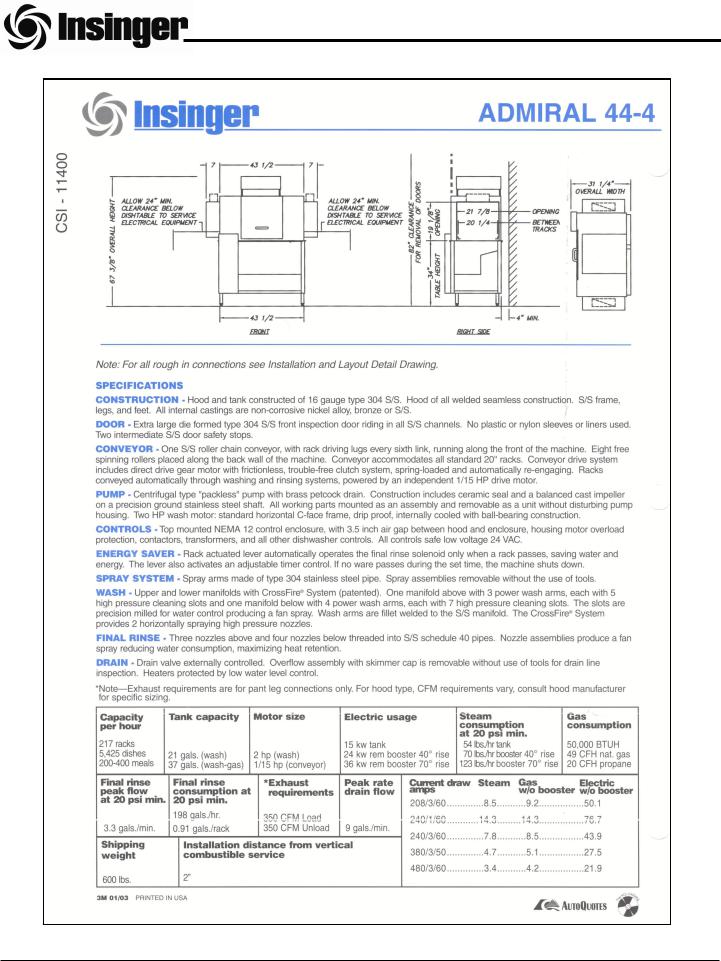
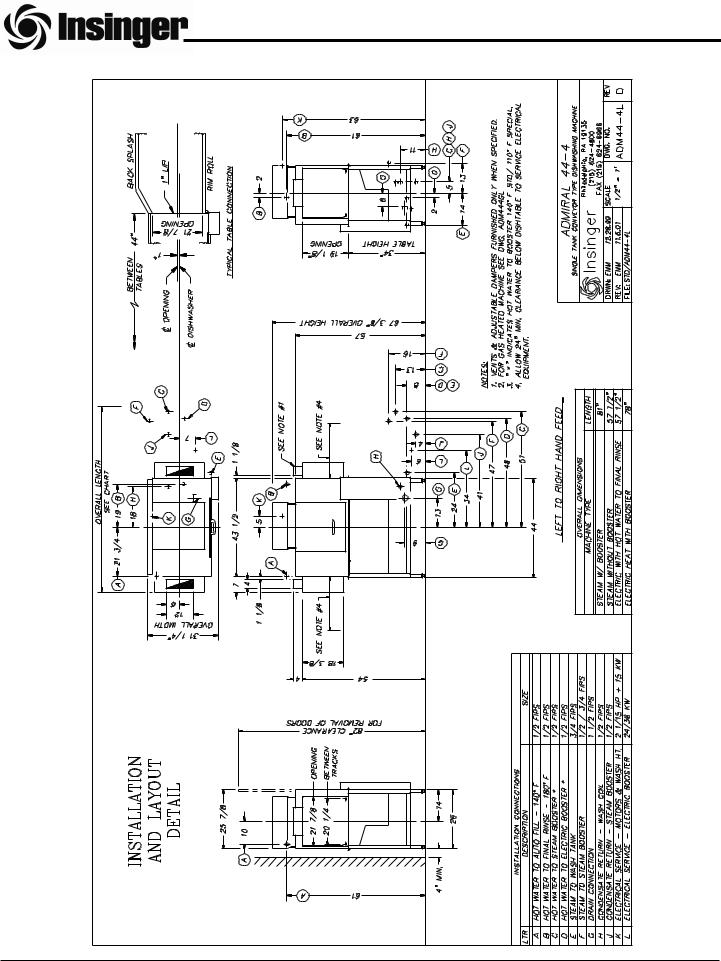
Admiral 44-4
Admiral 66-4
Installation, Operation, and Maintenance Instructions
Insinger Machine Company
6245 State Road
Philadelphia, PA 19135-2996
800.344.4802
Fax 215.624.6966 www.insingermachine.com

Thank you for purchasing this quality Insinger product.
On the space provided below please record the model, serial number and start-up date of this unit:
Model:__________________________________
Serial Number:___________________________
Start-Up Date:____________________________
When referring to this equipment please have this information available.
Each piece of equipment at Insinger is carefully tested before shipment for proper operation. If the need for service should arise please contact your local Authorized Insinger Service Company.
A Service Network Listing is provided on our web site, www.insingermachine.com or call Insinger at 800-344-4802 for your local authorized servicer.
For proper activation of the Insinger Limited Warranty a SureFire™ Start-Up & Check-Out Service should be completed on your machine. Refer to the Introduction section in this manual for an explanation of Insinger SureFire™ Start-Up & Check-Out Program.
Please read the Insinger Limited Warranty and all installation and operation instructions carefully before attempting to install or operate your new Insinger product.
To register your machine for warranty by phone, fax or the internet or for answers to question concerning installation, operation, or service contact our Technical Services Department:
TECHNICAL SERVICE CONTACTS
Toll-Free |
800-344-4802 |
|
|
Fax |
215-624-6966 |
|
|
service@insingermachine.com |
|
|
|
Web |
www.insingermachine.com |
|
|
TABLE OF CONTENTS
Part 1 |
|
Technical Information |
3-13 |
∙Introduction
∙Cut-sheets & Installation Drawings
∙Warranties
Part 2 |
|
Installation Instructions |
14-17 |
∙ Installation and Start-Up Procedures |
|
Part 3 |
|
Operating Instructions |
18 |
∙ Operating Procedures |
|
Part 4 |
19 |
Cleaning Instructions |
|
∙ Daily and Weekly Procedures |
|
Part 5 |
20-22 |
Maintenance & Repair Procedures |
∙ Maintenance & Repair Procedures
∙ Basic Service Guide
Part 6
Electrical Schematics & Replacement Parts 23-32
∙ Machine Wiring Diagrams |
|
∙ Control Panel Layout & Component |
Drawings |
Part 7 |
33 |
Spare Parts List |
|
Part 8 |
34-64 |
Replacement Parts |
∙ Overall Assembly Drawings for: Admiral 44-4 Admiral 66-4
∙Drain Assembly
∙Motor/Pump Assembly
∙Conveyor & Chain Tensioner Assemblies
∙Rinse Converter
∙Scrap Screen Arrangement
∙Top Baffles and Curtain Location
∙Drive Mechanism Assembly
∙Final Rinse Assemblies
∙Electric Heaters & Boosters
∙Steam Coils, Injectors and Boosters
∙Discharge Lines Assemblies
∙Rear Track Assemblies
Admiral Series DOC ADM-ES 1.0 04 |
www.insingermachine.com 800-344-4802 |

Admiral Series DOC ADM-ES 1.0 04 |
1 |
www.insingermachine.com 800-344-4802 |
Admiral Series DOC ADM-ES 1.0 04 |
2 |
www.insingermachine.com 800-344-4802 |

Admiral Series DOC ADM-ES 1.0 04 |
3 |
www.insingermachine.com |
800-344-4802 |
Admiral Series DOC ADM-ES 1.0 04 |
4 |
www.insingermachine.com |
800-344-4802 |

Admiral Series DOC ADM-ES 1.0 04 |
5 |
www.insingermachine.com 800-344-4802 |

Admiral Series DOC ADM-ES 1.0 04 |
6 |
www.insingermachine.com 800-344-4802 |

Admiral Series DOC ADM-ES 1.0 04 |
7 |
www.insingermachine.com |
800-344-4802 |

Admiral Series DOC ADM-ES 1.0 04 |
8 |
www.insingermachine.com |
800-344-4802 |
PART 1 TECHNICAL INFORMATION
ADMIRAL RACK CONVEYOR SERIES
INTRODUCTION
Purpose
The purpose of this technical manual is to provide installation, operation, cleaning and maintenance directions.
A section is provided for replacement parts.
Scope
This manual contains all pertinent information to assist in the proper installation, operation, cleaning, maintenance, and parts ordering for Insinger Rack Conveyor Admiral Dishwasher Series.
The installation instructions are intended for qualified equipment installers. The operation and cleaning instructions are intended for the daily users of the equipment. The maintenance and parts sections are intended for qualified service and/or maintenance technicians. Replacement parts may be ordered directly from our factory
or from your local Insinger Authorized Service Agency. You can speak to the Insinger Technical Services Department, 800/344-4802, or e-mail us at service@insingermachine.com. When calling for warranty information or replacement parts please provide the model and serial number of your Insinger Equipment. These important numbers should be noted in this manual on the spaces provided on the opening page.
Surefire™ Start-up & Check-out Program
Insinger is proud to offer our exclusive Surefire™ Start-up & Check-out Program to our commercial customers. This service is included in the purchase price of your new Insinger dishwasher. We will provide an authorized factory service technician for the initial start-up of your new Insinger dishwasher to ensure it is running at optimum levels from the very first pass. Please call the factory or your local Insinger Sales Representative to schedule this service.
NSF 3-2003 requirements for detergent
and chemical sanitizer dispensers.
This machine must be operated with an automatic detergent dispenser and, if applicable, an automatic chemical sanitizer feeder, including a visual means to verify that detergents and sanitizers are delivered or a visual or audible alarm to signal if detergents and sanitizers are not available for delivery to the respective washing and sanitizing systems. Please see instructions for electrical and plumbing connections located in this manual and in the feeder equipment manual.
Definitions
Throughout this guide you will find the following terms: WARNING, CAUTION, & NOTE.
WARNING indicates potential physical danger. CAUTION indicates potential equipment damage. NOTE indicates helpful operating hints or tips.
You will visually be able to identify each as shown below:
! |
WARNING: |
Indicates potential physical danger. |
þIndicates helpful operating hints or tips.NOTE:
CAUTION:
Indicates potential equipment damage.
Admiral Series DOC ADM-ES 1.0 04 |
9 |
www.insingermachine.com 800-344-4802 |

PART 1 TECHNICAL INFORMATION
INSINGER MACHINE COMPANY LIMITED WARRANTY
Insinger Machine Company, Inc. (Insinger) hereby warrants to the original retail purchaser of this Insinger Machine Company, Inc. product, that if it is assembled and operated in accordance with the printed instructions accompanying it, then for a period of either 15 months from the date of shipment from Insinger or 1 year (12 months) from the date of installation, that said Insinger product shall be free from defects in material and workmanship. Whichever one of the two aforestated limited warranty time periods is the longest shall be the applicable limited warranty coverage time period.
Insinger may require reasonable proof of your date of purchase; therefore, you should retain your copy of invoice or shipping document.
This limited warranty shall be limited to the repair or replacement of parts which prove defective under normal use and service and which on examination shall indicate, to Insinger’s satisfaction, they are defective. Any part that is claimed to be defective and covered by this limited warranty must be returned to Insinger, this may be done through an Authorized Service Agency. Furnish serial number of machine with shipment and send to:
Insinger Machine Company
6245 State Road
Philadelphia, PA 19135-2996
If Insinger’s inspection confirms the defect and the claim, Insinger will repair or replace such part without charge and return it to you freight or postage prepaid.
This limited warranty does not cover any failure or accident, abuse, misuse, alteration, misapplication, improper installation, fire, flood, acts of God or improper maintenance or service, or failure to perform normal and routine maintenance as set out in
the instruction booklet (operating instructions) or for improper operation or failure to follow normal operating instructions (as set out in the instruction booklet). Insinger is not responsible nor liable for any conditions of erosion or corrosion caused by corrosive detergents, acids, lye or other chemicals used in the washing and or cleaning process.
Service must be done by either Insinger Appointed Service Agencies or agencies receiving prior authorization from Insinger.
All warranty work must be done during normal working hours, unless purchaser receives prior authorization from Insinger.
There are no other express warrants except as set forth herein and any applicable implied warranties of merchantability and fitness are limited in duration to the period of coverage of this express written limited warranty. This limited warranty supersedes all other express warranties, implied warranties of merchant-ability and fitness or limited warranties as of this date, January 1, 1998. Some states do not allow limitation on how long an implied warranty lasts so this limitation may not apply to you.
Insinger is not liable for any special, indirect or consequential damages. Some states do not allow the exclusion or limitation of incidental or consequential damages, so this limitation nor exclusion may not apply to you.
Insinger does not authorize any person or company to assume for it any other obligation or liability in connection with the sale, installation, use, removal, return or replacement of its equipment: and no such representations are binding on Insinger.
Admiral Series DOC ADM-ES 1.0 04 |
10 |
www.insingermachine.com 800-344-4802 |

PART 1 TECHNICAL INFORMATION
INSINGER MACHINE COMPANY LIMITED WARRANTY COMMERCIAL MARINE USE
Insinger Machine Company, Inc. (Insinger) hereby warrants to the original retail purchaser of this Insinger Machine Company, Inc. product, that if it is assembled and operated in accordance with the printed instructions accompanying it (installation manual), then for a period of 18 months from the date of installation on board the vessel, that said Insinger product shall be free from defects in material and workmanship.
Insinger may require reasonable proof of your date of equipment install, therefore, you should retain your copy of invoice or shipping document.
This limited warranty shall be limited to the replacement of parts which prove defective under normal use and service and which on examination shall indicate, to Insinger's satisfaction, they are defective. Any part that is claimed to be defective and covered by this limited warranty must be returned to Insinger. Furnish serial number of machine with shipment and send to:
Insinger Machine Company, Inc.
6245 State Road
Philadelphia, PA 19135-2996
If Insinger's inspection confirms the defect and the claim, Insinger will repair or replace such part without charge and return it to you freight or postage prepaid. If part damages are not covered, Insinger will contact the customer and advise.
If a factory trained authorized technician is required to repair or replace defective parts or material during the 18 month warranty period, the cruise line will be responsible for the payment of travel expense and a minimum of four hours labor.
Labor will be billed to the customer at a reduced rate of $40.00 per hour. If sailing with a vessel is required, then an eight hour per day minimum will apply.
This limited warranty does not cover accident, abuse, misuse, alteration, misapplication, improper installation, fire, flood, or improper maintenance or service, or failure to perform normal and routine maintenance as set out in the instruction booklet (operating instructions) or for improper operation or failure to follow normal operating instructions (as set out in the instruction booklet).
Insinger is not responsible nor liable for any conditions of erosion or corrosion caused by corrosive detergents, acids, lye or other chemicals used in the washing, caring and or cleaning process.
Warranty service must be done by either Insinger Appointed Service Agencies or agencies, customers galley engineers receiving prior authorization from Insinger.
There are no other express warrants except as set forth herein and any applicable implied warranties of merchantability and fitness are limited in duration to the period of coverage of this express written limited warranty. This limited warranty supersedes all other express warranties, implied warranties of merchantability and fitness or limited warranties as the above date.
Insinger does not authorize any person or company locally or overseas to assume for it any other obligation or liability in connection with the sale, installation, use, removal, return or replacement of its equipment; and no such representations are binding on Insinger.
Admiral Series DOC ADM-ES 1.0 04 |
11 |
www.insingermachine.com 800-344-4802 |
PART 2 INSTALLATION INSTRUCTIONS
INSTALLATION INSTRUCTIONS
Placement
Carefully uncrate machine. Take caution not to damage components which may be mounted on the top or sides of the machine. Set unit in place and adjust the feet to level the machine.
Fasten the tables to the load and unload side of the machine. Most installations require fastening the turn-down lip of the dish table to the side of the machine with flathead counter-sunk screws. The table design should provide horizontal clearance of 30” for servicing underneath the table.
Electrical Connections
Connect electrical lines sized for the correct voltage, current and phase of the machine. These should agree with the machine requirements indicated on the nameplate and labels on the control panel.
On machines not provided with a single-point connection (optional) there is an electrical connection required for the: 1. Pumps and control circuit, 2.
Wash tank heater(s) and, 3. Rinse tank heaters (if provided).
If an electric booster is provided, connect power directly to the booster.
Fusing must be in accordance with the Fuse Sizing Chart below.
CAUTION:
Connections must be made to a circuit breaker or fused disconnect as provided by the end-user and required by local codes.
A laminated wiring diagram is inside the control panel.
FUSE SIZING CHART
Model |
208VAC/3È |
230VAC/3È |
380VAC/3È |
460VAC/3È |
220VAC/IÈ |
|
|
|
|
|
|
|
|
Admiral 44-4 |
15A |
10A |
10A |
6A |
20A |
|
Steam or Electric |
||||||
|
|
|
|
|
||
|
|
|
|
|
|
|
Admiral 44-4 |
15A |
15A |
10A |
6A |
25A |
|
Steam or Electric |
||||||
Power Loader |
|
|
|
|
|
|
|
|
|
|
|
|
|
Admiral 44-4 |
15A |
15A |
10A |
10A |
25A |
|
Steam or Electric |
||||||
Power Unloader |
|
|
|
|
|
|
|
|
|
|
|
|
|
Admiral 44-4 |
|
|
|
|
|
|
Steam or Electric |
20A |
15A |
10A |
10A |
25A |
|
Power Loader |
|
|
|
|
|
|
Power Unloader |
|
|
|
|
|
|
|
|
|
|
|
|
|
Admiral 44-4 |
15A |
15A |
10A |
6A |
20A |
|
Gas Heat |
||||||
|
|
|
|
|
||
|
|
|
|
|
|
|
Admiral 44-4 |
|
|
|
|
|
|
Gas Heat |
15A |
15A |
10A |
10A |
25A |
|
Power Loader |
|
|
|
|
|
|
Power Unloader |
|
|
|
|
|
|
|
|
|
|
|
|
|
Admiral 44-4 |
|
|
|
|
|
|
Admiral 66-4 |
60A |
50A |
30A |
25A |
n/a |
|
Electric Heat |
||||||
|
|
|
|
|
||
Single-Point Electric |
|
|
|
|
|
|
|
|
|
|
|
|
|
Admiral 44-4 |
|
|
|
|
|
|
Electric Heat |
60A |
50A |
30A |
25A |
n/a |
|
Single-Point Electric |
|
|
|
|
|
|
Power Unloader |
|
|
|
|
|
|
|
|
|
|
|
|
|
|
|
|
|
|
|
Admiral Series DOC ADM-ES 1.0 04 |
12 |
www.insingermachine.com 800-344-4802 |

PART 2 INSTALLATION INSTRUCTIONS
FUSE SIZING CHART
Model |
208VAC/3È |
230VAC/3È |
380VAC/3È |
460VAC/3È |
220VAC/IÈ |
|
|
|
|
|
|
|
|
Admiral 44-4 |
|
|
|
|
|
|
electric heat |
60A |
50A |
35A |
25A |
n/a |
|
single-point electric |
|
|
|
|
|
|
power unloader |
|
|
|
|
|
|
|
|
|
|
|
|
|
Admiral 44-4 |
|
|
|
|
|
|
electric heat |
60A |
50A |
35A |
25A |
n/a |
|
single-point electric |
||||||
power loader |
|
|
|
|
|
|
power unloader |
|
|
|
|
|
|
|
|
|
|
|
|
|
Admiral 66-4 |
15A |
15A |
10A |
6A |
25A |
|
steam or electric |
||||||
|
|
|
|
|
||
|
|
|
|
|
|
|
Admiral 66-4 |
15A |
15A |
10A |
10A |
35A |
|
steam or electric |
||||||
power loader |
|
|
|
|
|
|
|
|
|
|
|
|
|
Admiral 66-4 |
20A |
15A |
10A |
10A |
30A |
|
steam or electric |
||||||
power unloader |
|
|
|
|
|
|
|
|
|
|
|
|
|
Admiral 66-4 |
|
|
|
|
|
|
steam or electric |
20A |
20A |
10A |
10A |
30A |
|
power loader |
|
|
|
|
|
|
power unloader |
|
|
|
|
|
|
|
|
|
|
|
|
|
Admiral 66-4 |
15A |
15A |
10A |
10A |
25A |
|
gas heat |
||||||
|
|
|
|
|
||
|
|
|
|
|
|
|
Admiral 66-4 |
20A |
15A |
10A |
10A |
30A |
|
gas heat |
||||||
power loader or unloader |
|
|
|
|
|
|
|
|
|
|
|
|
|
Admiral 66-4 |
|
|
|
|
|
|
gas heat |
20A |
15A |
10A |
10A |
35A |
|
power loader and |
|
|
|
|
|
|
unloader |
|
|
|
|
|
|
|
|
|
|
|
|
|
Admiral 66-4 |
|
|
|
|
|
|
electric heat |
60A |
50A |
35A |
25A |
n/a |
|
single-point electric |
|
|
|
|
|
|
power loader or unloader |
|
|
|
|
|
|
|
|
|
|
|
|
|
Admiral 66-4 |
|
|
|
|
|
|
electric heat |
60A |
60A |
35A |
30A |
n/a |
|
single-point electric |
||||||
power loader and |
|
|
|
|
|
|
unloader |
|
|
|
|
|
|
|
|
|
|
|
|
|
Admiral 44-4¹ |
|
|
|
|
|
|
Admiral 66-4¹ |
60A |
45A |
30A |
25A |
80A |
|
electric heat |
||||||
|
|
|
|
|
||
non-SPC |
|
|
|
|
|
|
|
|
|
|
|
|
1 This circuit is required for all machines with electric tank heat that are not configured for single point connection.
CAUTION:
As with any 3 phase system, an electrician must check all motors for proper phasing, i.e., pump motors must be running in direction indicated by arrow on housing.
Admiral Series DOC ADM-ES 1.0 04 |
13 |
www.insingermachine.com 800-344-4802 |
PART 2 INSTALLATION INSTRUCTIONS
Mechanical Connections
Connect water lines for tank fills as tagged and noted on the installation drawings.
If machine is provided with steam heat connect the steam lines and steam condensate lines as tagged and noted on installation drawings. If machine is provided with gas heat, connect the gas line.
If a booster is provided a hot water connection is necessary (110º F or 140º F).
CAUTION:
Drain lines must be as specified on installation drawings.
Drain line should be properly vented and should have fall of not less than 1/4” to the foot of proper flow.
Some area plumbing codes require drains
to flow into an open gap with an opening twice the diameter of the pipe.
Check with your local plumbing codes for the type of drain connection required.
Chemicals
Upon the completed installation of the dishwasher, contact a local detergent/chemical supplier for the correct chemicals for your soil load and geographical area.
Electrical connection points for the detergent dispenser and rinse injector are located inside the control panel. Refer to the wiring diagram for this machine for the proper connection points.
Dispensers may be connected on either the primary voltage side of the machine or the 24VAC control voltage side.
CAUTION:
When connecting on the 24VAC control voltage side of the transformer, total VA must not exceed 5Kva.
The detergent density probe can be placed in the provided hole (labeled “Detergent Probe”) in the wash tank.
CAUTION:
All lines must be flushed prior to use to remove debris.
CAUTION:
Do not reduce the size of lines as specified in installation drawings. All lines are sized to facilitate necessary flows, pressures, etc.
HVAC
The ventilation system should be sized to provide adequate ventilation per machine specs. Refer to spec sheet.
Stainless steel, watertight ducting should be connected to the vent cowls (optional) on each end of the machine.
Tabling
Load and unload tables should be pitched towards the machine to return excess water into the machine.
CAUTION:
Machines with unload tables less than 48” should utilize a rack limit switch to shut the machine down if clean racks pile-up. This extends the life of the drive system.
Admiral Series DOC ADM-ES 1.0 04 |
14 |
www.insingermachine.com 800-344-4802 |

PART 2 INSTALLATION INSTRUCTIONS
Initial Start-Up Adjustments
Tank Overfill Adjustment
1.Locate tank overfill timer in the control panel. See the control panel layout drawing located in Section 6, Electrical Schematic and Replacement Parts.
2.The overfill timer starts timing when the upper level float is actuated. Adjust the overfill timer potentiometer to turn the tank fill solenoid off when the water level is 1/4” below the lip of the overflow tube.
3.The timer has a built in dwell timing delay of 5 seconds (nominal to dampen float bounce caused by tank water motion.
Conveyor Jam Adjustment
1.Remove the mechanism guard to gain access to the conveyor drive.
2.Locate the compression spring (refer to Drawing #1397-1, Drive Mechanism Assembly).
3.The factory set compression dimension is a nominal 3 13/16”. Installations washing heavier ware may need to adjust this for more compression to keep the machine from shutting down prematurely.
4.Should the drive mechanism switch be activated by a conveyor jam, the Check Conveyor Light on the control panel will illuminate and the machine will shut down.
5.To restart the machine, clear the jam and press the green Start Button.
Final Rinse Pressure Adjustment
1.The final rinse pressure must be adjusted to 20PSI. This is done by adjusting the pressure regulator.
Admiral Series DOC ADM-ES 1.0 04 |
15 |
www.insingermachine.com 800-344-4802 |

PART 3 OPERATION INSTRUCTIONS
Insinger dishmachines are user-friendly, making |
CAUTION: |
|
|
them the easiest dishmachines on the market to |
|
|
|
|
|
||
operate and maintain. |
Overloading racks will impede proper cleaning of the |
|
|
By following these operating procedures your |
ware and also put extra strain on the conveyor system. |
|
|
|
|
||
|
|
||
Insinger dishwasher will give you years of trouble |
|
|
|
free service. |
10. Slide the rack into the dishmachine, the conveyor |
||
|
|||
OPERATION INSTRUCTIONS |
11. will pass the rack through the various machine |
||
1. Ensure drain overflow tube is in place. Close all |
cycles. Upon entering the final rinse section of |
||
the machine the rack will engage the final rinse |
|||
tank drain valves. One drain is provided for |
actuator allowing the water to sanitize the dishes. |
||
each tank of the dishmachine. |
12. Should a conveyor jam occur, the CHECK CON- |
||
2. Check for proper installation and cleanliness of |
|||
VEYOR light will illuminate and the machine will |
|||
all internal, removable components such as |
shutdown. To re-start the machine, clear the |
||
suction strainers, scrap screens, and spray |
conveyor jam and press the GREEN START |
||
manifolds. |
button. If the CHECK CONVEYOR light comes |
||
3. Ensure all water, steam, and gas lines are |
back on, contact a qualified service technician. |
||
|
|
||
open. Ensure electrical circuits are on. |
13. Upon completion of ware cleaning depress the |
||
4. Close machine doors. |
RED button to stop the conveyor system. |
||
|
|
||
þAn interlock is provided to shut the machine down if the doors are open, therefore the machine will not run if the doors are opened.NOTE:
5.Move the power toggle switch to the ON position.
6.The machine will begin to fill.
7.When the tanks are full the tank heat will operate automatically.
CAUTION:
To ensure proper operation
of the auto tank fill feature and the tank heaters, the tank level floats MUST be cleaned daily.
8.Depress the GREEN button to start the conveyor.
9.The system is now ready for operation. All ware should be properly scrapped. Do not overload racks.
14.Move the POWER toggle switch to the OFF position.
15.Refer to the cleaning procedures for proper cleaning of the dishmachine.
16.Report any unusual occurrences to qualified service personnel.
Admiral Series DOC ADM-ES 1.0 04 |
16 |
www.insingermachine.com 800-344-4802 |

PART 4 CLEANING INSTRUCTIONS
The following cleaning procedures should be done daily, at the end of the shift.
DAILY CLEANING PROCEDURES
1.Remove all internal removable parts including spray manifolds, scrap screens, drain overflow tubes, suction strainers and curtains.
2.Remove the end caps from the spray manifolds and clean with the brush provided. Flush the manifolds.
3.Flush scrap screens.
4.Clean drain overflow tube.
þV-cup seal on the drain overflow tube may become gummed not allowing the overflow tube to seal. This will cause the drain to leak water. Remove any build-up on the V-cup seal. When the seal becomes worn, replace with part # D2-557.
5.Clean the suction strainers of build-up.NOTE:
þImproper cleaning of the suction strainers will cause the pumps to cavitate. This will cause poor washing results.
6.Clean the tank level float with a plastic abrasive pad (do not use steel wool).NOTE:
þ NOTE:
Level floats must be cleaned daily. Build-up of grease and dirt will cause faulty operation of the tank fill heating system.
The LIQUID LEVEL FLOAT is located below the scrap screens in those tanks which contain water heating devices (coils, steam injectors, or electric immersion heaters) and pump inlet strainers. They are usually located, in rackless and rack conveyor style machines, on the inside tank wall, at approximately water level, opposite and parallel to the inspection doors. In the door, stationary rack type machines, the LIQUID LEVEL FLOAT may be found beneath the scrap screen.
7.Clean curtains. When the curtains are beyond cleaning or torn they should be replaced.
8.Clean final rinse nozzles of matter clogging the jet spray.
9.Leave the doors open to allow the drying of the interior surfaces.
WEEKLY CLEANING PROCEDURES
An ENERGY SAVER SWITCH is provided on the control panel. When running the machine with de-liming solution, place this switch in the OFF position to allow the machine to run continuously. When not de-liming, the switch should be in NORMAL. Consult your detergent supplier for deliming solution concentration and frequency of use.
Admiral Series DOC ADM-ES 1.0 04 |
17 |
www.insingermachine.com 800-344-4802 |
PART 5 MAINTENANCE & REPAIR PROCEDURES
The following is a basic guide for the repair and replacement of common dishwasher parts. Refer to the Basic Services Guide for troubleshooting tips.
MAINTENANCE REQUIREMENTS
Daily
1.Refer to the operations and cleaning instructions provided in this manual for daily cleaning procedures.
Weekly
1.The entire machine should be wiped down using an industrial grade stainless steel cleaner.
2.Under the supervision of your detergent supplier the machine interior must be properly delimed.
3.A switch is provided on the control panel to run the machine continuously. For de-liming, move the selector switch to the DE-LIME position, then operate the machine normally. When deliming is completed, return the selector switch to “normal”.
þThe water quality in some areas requires de-liming to be done more frequently. Contact
your detergent supplier for recommended de-liming frequency.NOTE:
Quarterly
1.Remove and clean the strainer screens on the water and steam lines. If the screens cannot be cleaned, replace.
2.Inspect the condition of the solenoid valve seats, and diaphragms. Replace where necessary.
3.Inspect drain O-Rings for leakage. Replace where necessary.
4.Grease the drive chain and sprockets.
5.Adjust conveyor chain tension using adjustment bolts located on the exit ends of the machine.
MAINTENANCE PROCEDURES
Solenoid Valve Disassembly
1.Disconnect the power supply to the machine. Turn off the water supply.
2.Remove cap on top of the coil. Remove the coil.
3.Remove the 4 hex bolts and lift bonnet from valve body. Note positioning of spring and plunger.
4.Remove main piston.
5.Inspect for dirt, wear or lime build-up. Clean or replace as required.
6.Reassemble in reverse of disassembly.
Liner Strainer Disassembly
1.Shut off water or steam supply.
2.Remove large hex nut on bottom of strainer body.
3.Remove strainer screen. Inspect and clean or replace as necessary.
4.Reassemble in reverse of disassembly. Water flow must be same direction as arrow on line strainer body. Use new gaskets to insure a tight seal.
Pump Disassembly
1.Before disassembling pump ensure there are no obstructions in the pump intake. Remove and clean the suction strainer (inside tank). See dwg. SK-2456A
þIt is not necessary to remove the pump housing from the machine to disassemble pump.NOTE:
2.Remove the pump motor and impeller by removing the 4 hex bolts attaching them to the pump housing.
3.Repair or replace the pump parts as required.
4.Reassemble in reverse of disassembly.
Admiral Series DOC ADM-ES 1.0 04 |
18 |
www.insingermachine.com 800-344-4802 |
 Loading...