

Page 1

User Guide
Freedom Box 200C
Wireless Ruggedized Modem
Warning: You must install the modem software before inserting the FB200C modem.
TM
For Windows 2000 and XP
Page 2

Notice: Restricted Proprietary Information
© Copyright Novatel Wireless Inc. (2003)
The information contained in this document is the exclusive property of Novatel Wireless Inc. All rights reserved. Unauthorized reproduction
of this manual in any form without the expressed written approval of Novatel Wireless Inc. is strictly prohibited. This manual may not, in
whole or in part, be copied, reproduced, translated, or reduced to any electronic or magnetic storage medium without the written consent of a
duly authorized officer of Novatel Wireless Inc.
The information contained in this document is subject to change without notice and should not be construed as a commitment by Novatel
Wireless Inc. unless such commitment is expressly given in a covering document.
Novatel Wireless Inc. makes no warranties, either expressed or implied, regarding this document, its merchantability, or its fitness, for any
particular purpose.
Microsoft
®
and Windows® are either registered trademarks or trademarks of Microsoft Corporation in the United States and/or other countries.
All other brand names and product names used in this document are trade names, service marks, trademarks, or registered trademarks of their
respective owners.
The Novatel Wireless logo and Freedom Box 200C are trademarks of Novatel Wireless, Inc.
Produced in the USA.
Page 3

Table of Contents 3
Table of Contents
Table of Contents
Technical Support
Safety and Regulatory Notices .............................................................................................................. 3
Regulatory Notices................................................................................................................................. 3
Technical Support .................................................................................................................................. 3
System Requirements............................................................................................................................ 3
FB200C Overview and Installation............................................................ 5
FB200C front panel................................................................................................................................ 5
FB200C Rear Panel............................................................................................................................... 6
Connecting the power cable .................................................................................................................. 7
Installing the Wireless Connection Manager Software on Windows ....9
Uninstalling the Wireless Connection Manager Software .................................................................... 12
Getting Started With the Wireless Connection Manager...................... 13
Connecting to the Network................................................................................................................... 13
Disconnecting From the Network......................................................................................................... 17
Quitting the Wireless Connection Manager Application....................................................................... 17
System Tray Icons ............................................................................................................................... 18
Getting to Know the Wireless Connection Manager for Windows ...... 19
The Wireless Connection Manager Main Window ............................................................................... 19
The Modem Configuration Window...................................................................................................... 20
The Modem Properties Window........................................................................................................... 21
The Detailed Status Report Window.................................................................................................... 23
The About Wireless Connection Manager Window ............................................................................. 24
Additional Menu Commands................................................................................................................ 25
Troubleshooting
Troubleshooting a Connection Failure ................................................................................................. 27
Error Messages.................................................................................................................................... 28
Frequently Asked Questions................................................................................................................ 29
Index.......................................................................................................... 31
Manual Revision A for Windows
Page 4

4 Table of Contents
Manual Revision A for Windows
This Page Intentionally Left Blank
Page 5

Technical Support —
Technical Support
Safety and Regulatory Notices
This product is not to be used in any environment where radio frequency equipment is prohibited
or restricted in its use. To ensure that your modem is deactivated you should remove it from your
computer under the above conditions.
Regulatory Notices
Federal Communications Commission Radio Frequency Interference Statement
This equipment has been certified to comply within the limits of a class B digital device pursuant
to part 15 and 24 of the FCC Rules. These limits are designed to provide reasonable protection
against harmful interference in residential situations. This equipment generates, uses, and can
radiate radio frequency energy, and, if not properly installed and used in accordance with the
instructions, may cause harmful interference to radio or television reception, which can be
determined by turning the equipment on and off. You are encouraged to try to correct the
interference by one or more of the following measures:
Reorient or relocate the receiving antenna of the television, radio or cordless telephone.
• Increase the separation between the equipment and the receiver.
• Connect the equipment to an outlet on a circuit different from that to which the receiver is
connected.
• Consult the dealer or an experienced radio/television technician for additional suggestions.
Technical Support
If you have any questions or comments about your FB200C, please contact the Novatel Wireless
Inc. Customer Support team.
WWW: http://www.novatelwireless.com/support/index.html
Email: support@novatelwireless.com
Phone: 1 (888) 888-9231
System Requirements
The following items are required to set up and use your FB200C modem:
• Pentium 90 processor or higher.
• Windows 2000 or XP
•64MB RAM
• 16MB hard drive space.
Manual Revision A for Windows
Page 6

Technical Support —
• CD-ROM drive.
• the Wireless Connection Manager software, included with your FB200C modem, and
• a user account, including a User Name and Password, from a network carrier with PCS CDMA
1X service.
To purchase a user account, please contact network carrier. For a list of network service provider
please email Novatel Wireless at support@novatelwireless.com or call 1 (888) 888-9231.
Manual Revision A for Windows
Page 7

7
FB200C Overview and Installation
This section provides an overview of the modem box and installation instructions.
FB200C front panel
The FB200C front panel has power, service, and data status indicators and a reset button as
shown on Figure 1.
Figure 1 FB200C Front Panel
Indicator/Button Function
Reset Reset button for the FB200C.
Power The power LED indicates power is on when lit.
Service The service LED indicates that the FB200C has acquired
network service.
Data The data LED indicates data activity between the
FB200C and the host computer.
Manual Revision A for Windows
Page 8
8
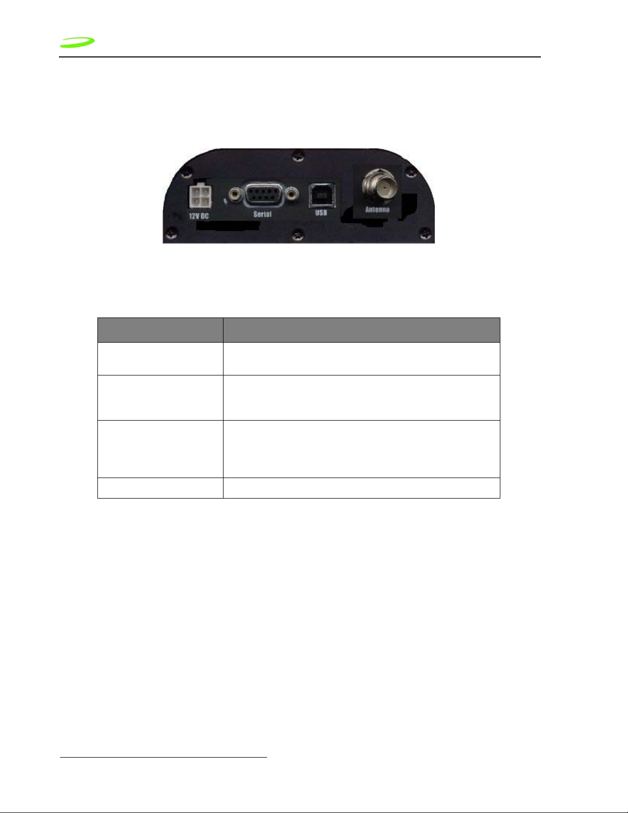
FB200C Rear Panel
The rear panel of the FB200C is where the power, communication port, and antenna cables are
connected. This is shown in Figure 2.
Figure 2 FB200C Rear Panel
Connector Description
12V DC Power cable plugs into this connector. The input supply
should be between 10 to 18 Volts DC.
Serial RS232 connector for modem main port. When using this
port, the modem acts as a AT modem. The Serial port is
disconnected when an active USB port is connected.
USB USB modem port. When using the USB port, the host
computer will have additional modem status information
not available when using the serial connector. USB must
be used when using Windows Connection Manager.
Antenna TNC antennae connector for external mount antennae.
Manual Revision A for Windows
Page 9

9
Connecting the power cable
The FB200C comes supplied with a power cable as illustrated in Figure 3.
Figure 3 Power cable
Wire Color Functionality
Green This wire is the positive terminal for the modem. The
modem is designed to be always on when power is
applied. Connect the green wire to vehicle IGN (IGNITION) if you only want the modem on when vehicle is on.
Connect the green wire to an always on fuse protected circuit connection to have modem always on.
Black Ground
Manual Revision A for Windows
Page 10

10
Manual Revision A for Windows
Page 11
11
Installing the Wireless Connection Manager Software on Windows
This section guides you step-by-step through the Wireless Connection Manager for Windows
installation procedure.
Once you have completed the set up and installation process, you will be able to use your
FB200C Modem with your Internet applications.
Warning: This application is only supported by Windows 2000 and XP
To install the Wireless Connection Manager onto your laptop or notebook computer:
1. Insert the Installation CD into the CD-ROM drive of your desktop computer. Run the
installation program WirelessConnectionManagerVx.xx.xx.exe.
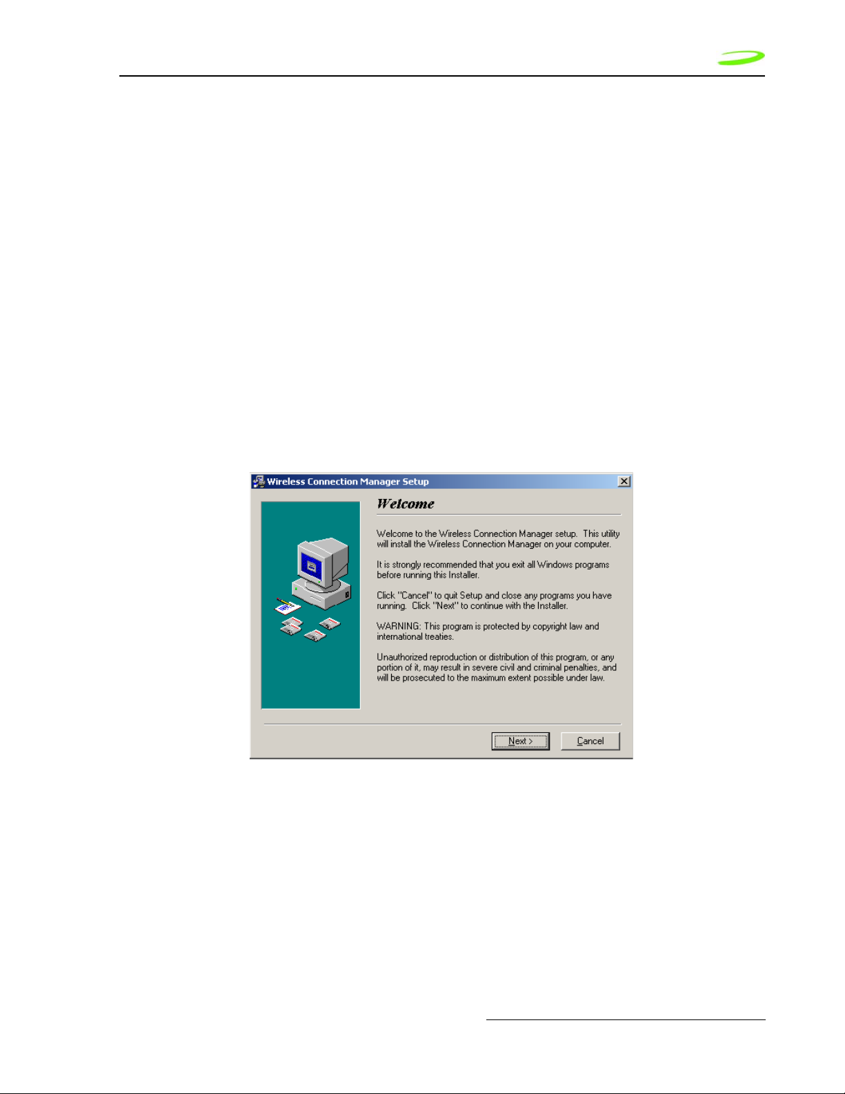
2. Follow the instructions displayed on screen to begin installing the Wireless Connection
Manager software. The Welcome window will appear, shown in Figure 1.
Figure 1 Welcome Window
Manual Revision A for Windows
Page 12

12
3. Read the information displayed on screen and click Next to continue. The Novatel Wireless
License Agreement will appear.
4. Read the agreement and select I read and agree to the above terms.
5. Click Next to continue. The Start Copying Files window will appear, shown in Figure 2.
Figure 2 Start Copying Files Window
Manual Revision A for Windows
Page 13

13
6. If you would like to review or change an installation setting, click Back. If you are satisfied
with the installation settings click Next to continue. The Installation Complete window will
appear, shown in Figure 3.
Figure 3 Installation Complete Window
7. Click Finish to exit the Installation program. The Install window will appear, shown in Figure
4.
Figure 4 Install Window
8. Click OK to restart your computer.
9. Once your computer has rebooted, make sure the modem is powered on by checking to
make sure the Power indicator is ON. Connect the FB200C’s USB cable into the computer’s
USB port. Windows will automatically detect and install the necessary modem drivers in
order to operate the FB200C modem.
10. When Windows has finished installing the FB200C modem drivers, you can access the
Wireless Connection Manager by double-clicking on the shortcut icon that has been placed
on your computer’s desktop.
Manual Revision A for Windows
Page 14

14
Uninstalling the Wireless Connection Manager Software
To uninstall the Wireless Connection Manager application, select Start -> Programs -> Novatel
Wireless -> Wireless Connection Manager -> Wireless Connection Manager Uninstall. The
Uninstall wizard will open, and guide you through removing the Wireless Connection Manager
program from your computer or by using the Windows Control panel and selecting "Add or
Remove Programs".
Manual Revision A for Windows
Page 15

15
Getting Started With the Wireless Connection Manager
The Wireless Connection Manager application allows you to monitor and control the operation of
your FB200C modem.
This section explains the basic steps required to operate the Wireless Connection Manager for
Windows.
Connecting to the Network
In order to use your Internet applications, your modem must first establish a network connection.
To connect to the network:
1. Launch the Wireless Connection Manager application by double-clicking the Wireless
Connection Manager icon, located on your desktop.
2. From the Wireless Connection Manager Main window, click Connect. See Figure 1.
Figure 1 Wireless Connection Manager Main Window
Manual Revision A for Windows
Page 16

16
3. If this is the first time you have attempted to connect to the network, the Wireless
Connection Manager will walk you through the 5 step activation process. See Figure 2.
Figure 2 Welcome Message
4. Click Next. The Activation Information window will appear, as shown in Figure 3.
Manual Revision A for Windows
Figure 3 Activation Information Window
Page 17

17
5. Click Next. When the enterprise administrator provides you with the activation code, enter
the number as indicated in Figure 4.
Figure 4 Activation code window
6. Click Next. Enter the phone number and MSID given by the Customer Solutions Advocate
as shown in Figure 5.
Figure 5 MDN and MSID window
Manual Revision A for Windows
Page 18

18
7. Click Next. The FB200C modem is activated properly when you see the successful
activation window as shown in Figure 6. Click Finish to close activation window.
Figure 6 successful activation window
8. The modem's network connection status will be displayed in the Modem status bar,
highlighted in Figure 7.
Figure 7 Modem Status Bar
If the modem is unable to connect to the network, check the modem’s signal strength as displayed
in the Signal Strength status bar. The greater the number of green bars present, the stronger
the signal strength. If the signal strength is poor, try changing your location in order to pick up a
stronger signal.
Manual Revision A for Windows
Page 19

19
Disconnecting From the Network
To disconnect your modem from the network, click Disconnect from the Wireless Connection
Manager Main window, shown in Figure 8.
Figure 8 Disconnect Button
To disconnect from the network and close the Wireless Connection Manager application, click the
located in the top-right corner of the Wireless Connection Manager Main window.
Alternately, you can select Exit from the Modem menu.
Quitting the Wireless Connection Manager Application
To quit the Wireless Connection Manager application, click the located in the top-right corner
of the Wireless Connection Manager main window.
Alternately, you can select Exit from the File menu, shown in Figure 9.
Figure 9 Exit Command
Manual Revision A for Windows
Page 20

20
The modem will terminate its network connection, and the Wireless Connection Manager
application will shut down.
System Tray Icons
When you launch the Wireless Connection Manager application, a system tray icon will appear
in the bottom-right corner of your desktop. These tray icons provide easy access to the Wireless
Connection Manager Main window and the modem’s connection status.
The following icons indicate the modem’s connection status:
- If this icon is visible, the modem is currently connected to the network.
- If this icon is visible, the modem is not connected to the network.
If the Wireless Connection Manager window is not visible, double-click the tray icon to open it.
Alternately, you can control the operation of the Wireless Connection Manager by right-clicking
the tray icon and selecting an action from the pop-up menu.
Manual Revision A for Windows
Page 21

21
Getting to Know the Wireless Connection Manager for Windows
This section introduces the various windows and menu commands that are contained in the
Wireless Connection Manager application for Windows.
The Wireless Connection Manager Main Window
When you launch the Wireless Connection Manager application for Windows, the Main window
will open, shown in Figure 1.
Figure 1 Wireless Connection Manager Main Window
The Wireless Connection Manager main window consists of the following items:
Duration Field This field indicates how long the modem has been con-
nected to the network.
Bytes Sent Field This field indicates the amount of data (bytes) the
modem has sent during the current network session.
Bytes Received Field This field indicates the amount of data (bytes) the
modem has received during the current network session.
Signal Strength Status Bar
Modem Status Bar This status bar displays the modem’s network connec-
This status bar indicates the modem’s signal strength. If
adequate signal strength is present, a number of the five
bars will be shaded green.
tion status.
Manual Revision A for Windows
Page 22

22
The Modem Configuration Window
To access the Modem Configuration window, shown in Figure 2, select Configuration from the
Modem menu.
Figure 2 Modem Configuration Window
The following fields are displayed in the Modem Configuration window:
Network Service Field This value directs the modem to attempt to connect only
with your service provide’s network. This is a read-only
field and cannot be altered.
Receive Next Call As
Field
Current System Time
Field
Current CDMA Time
Field
Show Connection
Properties While Connecting Check Box
Data Only - This value directs the modem to receive the
next call as packet data only. This is a read-only field
and cannot be altered.
This field displays the current system time as displayed
on your computer’s desktop.
This field displays the time as indicated by the CDMA
base station.
Select this check box if you wish to see the Connection
Properties window the next time you attempt to connect
to the network.
Manual Revision A for Windows
Page 23

23
The Modem Properties Window
To access the Modem Properties window, select Properties from the Modem menu
.
Figure 3 Modem Properties Window
The information contained in this window is useful for Customer Support in diagnosing problems
you may experience while using your modem.
Manual Revision A for Windows
Page 24

24
The following fields are contained in the Modem Properties window:
User Name This field displays your network user name.
Mobile Identification
Number
This field displays your modem’s Mobile Identification
Number. This number is used by the CDMA base station
to identify your modem.
ESN (HEX) This field displays your modem’s Electronic Serial Num-
ber (ESN). The ESN is a unique number given to each
modem as a means of identification.
PRL Version This field displays your modem’s Preferred Roaming List
(PRL) version. The PRL is a list of networks your modem
would prefer to connect with.
Firmware Version This field displays the firmware version your modem
uses.
Hardware Version This field displays the hardware version your modem
uses.
Modem Type This field displays the type of modem core your modem
uses.
Manufacturer This field displays the name of the firmware manufactur-
ing company.
Manual Revision A for Windows
Page 25

25
The Detailed Status Report Window
To access the Detailed Status Report window, select Detailed Status Report from the Tools
menu.
The Detailed Status Report window contains two tabs; the General and History tabs.
Figure 4 General Tab
The General tab, shown in Figure 4, is displayed by default and contains the following items:
Modem Status Bar This status bar displays the modem’s network connec-
tion status.
Total Bytes Transferred Field
Bytes Sent Field This field displays the total number of bytes sent, during
Bytes Received Field This field displays the total number of bytes received
Date Byte Totals Were
Last Cleared Field
This field displays the total number of bytes, both sent
and received, during the current network session.
the current network session.
during the current network session.
This field displays the date the byte totals were last
cleared.
Manual Revision A for Windows
Page 26

26
The History tab, shown in Figure 5, displays the date, time, and current modem and network
session activities. This tab is useful when attempting to diagnose problems with either your
modem or network connection.
Figure 5 History Tab
The About Wireless Connection Manager Window
To access the About Wireless Connection Manager window, shown in Figure 6, select About
Wireless Connection Manager from the Help menu.
Figure 6 About Wireless Connection Manager Window
This window contains information about the Wireless Connection Manager application, including:
• The software version
• The date the software was released
• The copyright information
Manual Revision A for Windows
Page 27

27
Additional Menu Commands
The following menu commands are also available from the Wireless Connection Manager
application.
Clear Bytes Command
To clear the modem’s total bytes counted, select Clear Bytes from the Tools menu.
All byte totals counted, either sent or received, by the modem during the current network session
will be cleared.
The modem’s byte totals are displayed in the General tab of the Detailed Status Report window,
shown in Figure 7.
Figure 7 Total Bytes Counter
Always on Top Command
To keep the Wireless Connection Manager window on top of all other windows, select Always
on Top from the Window menu, as shown in Figure 8.
Figure 8 Always on Top Command
Manual Revision A for Windows
Page 28

28
Note: Click Always on Top a second time to disable this command.
Hide Window Command
To hide the Wireless Connection Manager window, select Hide Window from the Window
menu, as shown in Figure 9.
Figure 9 Hide Window Command
The Wireless Connection Manager window will be minimized to the system tray icon .
Double-click on the icon to re-open the Wireless Connection Manager window.
Wireless Connection Manager Help
To access the online help for the Wireless Connection Manager application, select Wireless
Connection Manager Help from the Help menu, as shown in Figure 10. The application will
launch the Wireless Connection Manager online help files.
Manual Revision A for Windows
Figure 10 Wireless Connection Manager Help Command
Page 29

Troubleshooting 29
Troubleshooting
This section provides solutions to problems you may encounter while using your FB200C Modem
on a Windows operating system.
You can contact Novatel Wireless representative at support@novatelwireless.com or 1 (888)
888-9231 for additional information.
Troubleshooting a Connection Failure
If you are unable to establish a network connection, the following suggestions may correct the
problem:
• Verify that your FB200C modem is powered on and communication port is connected to
the computer.
• If the Wireless Connection Manager cannot communicate with the modem, exit the
Wireless Connection Manager application. Reset your FB200C Modem by using a thin
pen tip to push the reset button. This resets the modem hardware.
• Check your modem’s signal strength (displayed on the Wireless Connection Manager
Main window). If the signal strength is weak (less than two bars), your modem might be
unable to establish a network connection. Try moving to another location in order to pick
up a stronger signal.
• Launch the Wireless Connection Manager application and try to connect to the network
again.
Manual Revision A for Windows
Page 30

30 Troubleshooting
Error Messages
One of the following messages may be displayed if your modem is unable to register or connect
with the Mobile Network.
Message Solution
Modem Not
Responding
No Service If this message is displayed, there is no service available at this time.
Modem is not
present
Modem is already in
use
Device firmware
incompatible
This message may appear if you plug your FB200C modem into the USB
port and click on the Wireless Connection Manager shortcut icon before
your computer has detected the modem. Click OK on the message
window and wait between 15-30 seconds before clicking the shortcut
icon. If the message appears a second time, unplug and reconnect the
USB port to the modem and wait until your computer detects the modem
before clicking the Wireless Connection Manager shortcut icon again.
The network could be busy or undergoing maintenance. Try connecting
to the network at a later time or moving to another location if you are
outside the network’s coverage area.
If this message is displayed, verify that the modem USB cable is
plugged in properly. Note: Modem detection is only available when the
modem is connected using the USB port.
This message indicates the modem port is busy. Verify whether your
modem has already established a network connection. If the modem is
not currently connected to the network, exit the Wireless Connection
Manager program, relaunch the application and try a second time to
connect to the network.
If this message appears, your FB200C modem’s firmware is
incompatible with your current version of the Wireless Connection
Manager software. Please contact Novatel Wireless customer support
in order to upgrade your modem’s firmware.
There was no
answer
The remote access
server is not
responding
The modem has
reported an error
Manual Revision A for Windows
If this message appears, try and connect at a later time. If the message
appears again, contact your service provider customer support.
If this message appears, try and connect at a later time or move to a
better signal strength location. If you still cannot connect to the network,
contact your service provider customer support.
If this message is displayed, reboot your computer and try to connect
again. If you are still unable to connect, contact your service provider
customer support.
Page 31

Troubleshooting 31
Frequently Asked Questions
Question Answer
How can I check the
quality of my
connection?
How do I find out
what version of the
Wireless
Connection
Manager software
I’m using?
How do I find out
what version of
firmware and
hardware my
modem is using?
I have forgotten my
User Name and
Password. What do I
do?
How can I tell if I
have service?
The Signal Strength status bar, located on the Wireless Connection
Manager Main window, indicates the quality of the modem’s signal. If
two or more bars are shaded green, the modem’s signal strength is
good. If less than two bars are shaded green, the signal strength is poor
and it will be difficult to establish and maintain a network connection.
Open the Wireless Connection Manager Main window and select About
Wireless Connection Manager from the Help menu. The Wireless
Connection Manager software version, release date, and copyright
information will be displayed in the About Wireless Connection
Manager window.
Open the Wireless Connection Manager Main window and select
Properties from the Modem menu. The modem’s firmware and
hardware version, as well as the modem type and manufacturer, will be
displayed in the Modem Properties window.
Call your network service provider customer support.
The Wireless Connection Manager indicates whether you have service.
The Wireless Connection Manager will indicate if there is no service
available in the Modem Status field.
What is an ESN? An ESN (electronic serial number) is a unique number that identifies
your wireless modem to the network. You can check your modem’s ESN
by selecting Properties from the Modem menu.
Why won’t the
Wireless
Connection
Manager recognize
my User Name or
Password?
Verify that you are entering the correct information in the Connection
Properties window. If the Caps Lock feature is activated, turn it off and
enter the information again. If the problem persists, call Customer
Support of the network service provider to verify you have the correct
User Name and Password.
Manual Revision A for Windows
Page 32

32 Troubleshooting
Manual Revision A for Windows
Page 33

Index
A
About Wireless Connection Manager Window
Windows 24
C
Connecting to the Network
Windows 5, 13
Connection Failure
Error Messages 28
Troubleshooting 27
D
Detailed Status Report Window 23
General Tab 23
History Tab 24
Disconnecting from the Network
Windows 6, 17
E
Error Messages 28
F
Frequently Asked Questions 29
G
General Tab
Bytes Received Field 23
Bytes Sent Field 23
Date Byte Totals Were Last Cleared Field
23
Detailed Status Report Window 23
Modem Status Bar 23
Total Bytes Transferred Field 23
H
Help 26
History Tab
Detailed Status Report Window 23
M
Modem Configuration Window
Current CDMA Time Field 20
Current System Time Field 20
Network Service Field 20
Receive Next Call As Field 20
Show Connection Properties Check Box 20
Windows 20
33
Modem Manager
About Wireless Connection Manager Win-
dow 24
Detailed Status Report Window 23
General Tab 23
History Tab 24
Help 26
Main Window 19
Modem Properties Window 21
Quitting 7, 17
Windows Installation 9
Windows Modem Configuration Window
20
Modem Manager for Windows
Starting 13
Modem Manager Main Window
Bytes Received Field 19
Bytes Sent Field 19
Duration Field 19
Modem Status Bar 19
Signal Strength Status Bar 16, 19
Windows 19
Modem Properties Window
ESN (HEX) Field 22
Firmware Version Field 22
Hardware Version Field 22
Manufacturer Field 22
Mobile Identification Number 22
Modem Type Field 22
PRL Version Field 22
Windows 21
N
Network
Disconnecting from 6, 17
S
Signal Strength Status Bar 16
Software Installation
Windows 9
System Tray Icons 18
T
Total Byte Counter 25
Troubleshooting 27
Connection Failure 27
Error Messages 28
Frequently Asked Questions 29
Manual Revision A for Windows
Page 34

34
W
Windows Commands
About Wireless Connection Manager 24
Always on Top 25
Clear Total Bytes 25
Configuration 20
Detailed Status Report 23
Exit 17
Hide Window 26
Wireless Connection Manager Help 26
Properties 21
Manual Revision A for Windows
 Loading...