

Page 1
Novatel Wireless Inc.
Version 2.1
Novatel Wireless, I nc .
PCI Express Mini-card
Installation Guidelines for E351
Version 2.1
Page 1 of 18
Page 2

Novatel Wireless Inc.
Version 2.1
Notice: Restricted Proprietary Information
© Copyright Novatel Wireless, Inc. (2012)
The information contained in this document is the exclusive property of Novatel Wireless, Inc. All
rights reserved. Unauthorized reproduction of this manual in any form without the expressed
written approval of Novatel Wireless, Inc. is strictly prohibited. This manual may not, in whole or in
part, be copied, reproduced, translated, or reduced to any electronic or magnetic storage medium
without the written consent of a duly authorized officer of Novatel Wireless Inc.
The information contained in this document is subject to change without notice and should not be
construed as a commitment by Novatel Wireless Inc. unless such commitment is expressly given
in a covering document.
Novatel Wireless Inc. makes no warranties, either expressed or implied, regarding this document,
its merchantability, or its fitness, for any particular purpose.
Printed and produced in United States of America.
Page 2 of 18
Page 3
Rev.
Date
Brief Description of Change
Originator
Approved by
1.0
August 6, 2011
Initial Draft
Todd Gallagher
2.0
February 3, 2012
Responses to FCC
Inquiries Tracking# 409406
Roman Olmos
Todd Gallagher
2.1
February 22, 2012
Update made to 1900MHz
Antenna Gain Information
Roman Olmos
Todd Gallagher
Document Revision History
Novatel Wireless Inc.
Version 2.1
Page 3 of 18
Page 4
Novatel Wireless Inc.
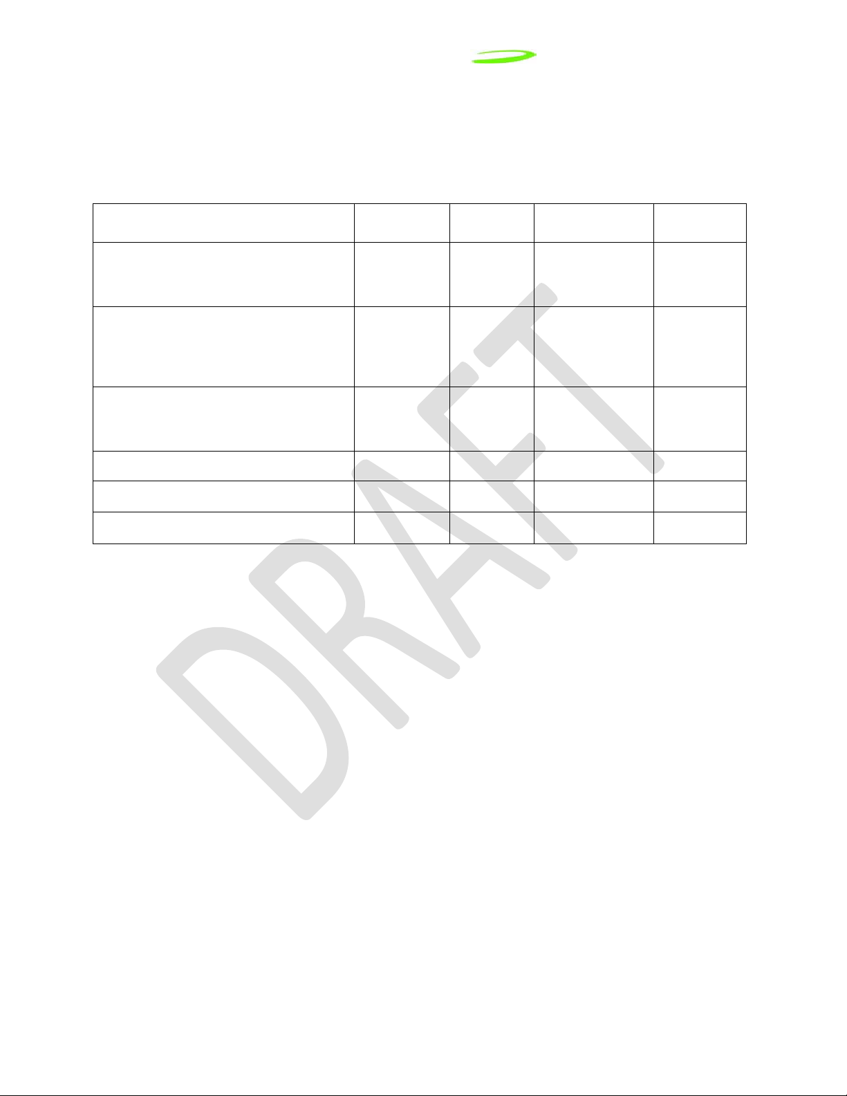
KDB Title
Version
Date
Attachment
Number
Version
Number
FCC KDB Publication Reference
Version 1.0
SAR Evaluation Considerations for
Laptop/Notebook and Tablet computers
Mobile and Portable Device
RF Exposure Procedures and
Equipment Authorization Policies
SAR Considerations for LTE Handsets
and Data modems
Modular Transmitter Approvals KDB 996369 07/12/2011 D01 v01r03
Permissive Change Policy KDB 178919 06/08/2011 D01 v05r01
Software Configuration Control KDB 594280 06/08/2011 D01 v01r01
KDB 616217 11/13/2009 D03 v01
KDB 447498 11/13/2009 D01 v04
KDB 941225 12/15/2010 D05 v01
Page 4 of 18
Page 5

Novatel Wireless Inc.
Version 1.0
E351 Module Installation and Collocation Guidelines
1.0 Introduction
This document provides collocation and installation instructions for future laptop computers through a
FCC Class I or a Class II Permissive Change based on the PKRNVWE351 SAR data and evaluation.
This process is documented in FCC KDB 616217 D03 and KDB 447498. Other configurations not
specifically described in this document may be authorized in a Class I permissive changes through
coordination with Novatel Wireless Inc. to verify that all technical requirements defined in FCC KDB
616217 D03 or other relevant FCC specifications are adequately addressed.
For other basics and details about FCC RF exposure compliance requirements for mobile and portable
devices, see FCC OET Bulletin 65 Supplement C.
The following installation host configurations are addressed in this document.
1) The E351 module can be installed as a standalone transmitter in notebooks meeting the
following conditions:
Mobile device notebooks where >20cm separation distance is provided between the
a.
WWAN antenna and the end user can be processed as a Class I change. The
technical parameters for mobile measurements are defined in Section 2.1.1.
Portable device notebooks where ≤20cm separation distance is provided between the
b.
WWAN transmitting antenna that meet the technical parameters defined in Section
2.1.2. These parameters define the conservative notebook configuration used as the
baseline host to evaluate SAR.
Note: “Standalone” condition is defined where a single transmitter is transmitting, as opposed
to two or more transmitters transmitting simultaneously.
2) This module was evaluated with a PIFA antenna (manufacturer xx, model xxx). As the
antenna is an integral part of the integration each antenna type will be subject to will be
subject to additional RF exposure evaluation and certification if applicable. The E351 will allow
collocated transmission through a Class I or Class II permissive change. The collocated
transmitters must meet the technical requirements defined in Secti on 4.0. and only after such
Class I or Class II is complete and according to its conditions.
3) Allow end-user installation prov ide d m odule/ not ebo ok Two-Way Authentication has been
addressed so that modules can only be activated in approved notebooks
4) The FCC ID must be permanently affixed on the exterior of the notebook so that it cannot be
separated from the host device itself.
PKRNVWE351
5) Per KDB 594280 Novatel Wireless Inc. will maintain control over settings that could allow the
product to operate outside the FCC rules.
6)
These installation guidelines are not applicable to non-notebook host devices or tablet
PCs. The installation guidelines are applicable for notebook computers where the E351
antennas and collocated antennas are located in the display portion of a notebook
computer. SAR evaluation is completed with the display open at a ninety-degree angle
as defined in KDB pub 616217 and Section 4 of KDB pub 447498.
The label used must state; Contains FCC ID:
Page 5 of 18
Page 6
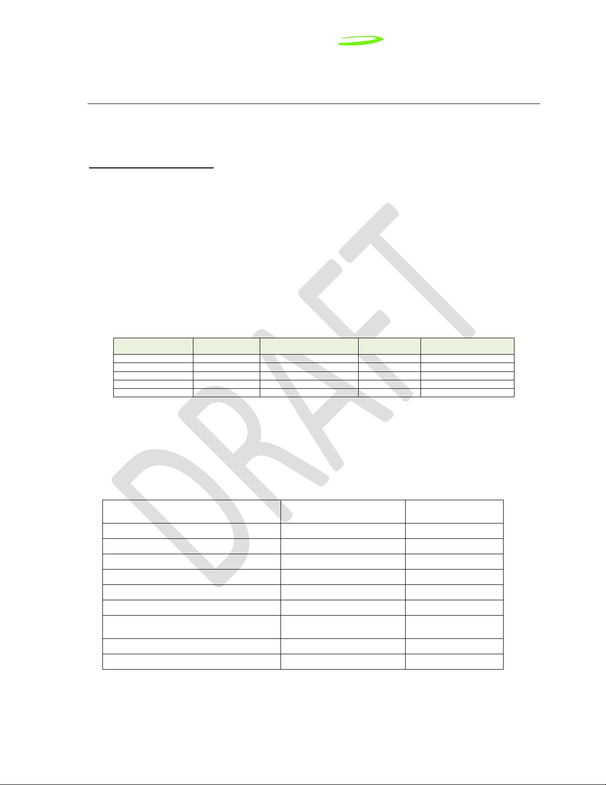
Novatel Wireless Inc.
Maximum Conducted
Power (dBm)
Conducted
Power (W)
Maximum Antenna Gain
(dBi)
LTE Band 13 (5MHZ)
779.5
24.25
0.266
5.0
LTE Band 13 (5MHz)
784.5
24.25
0.266
5.0
LTE Band 13 (10MHz)
782
24.25
0.266
5.0
CDMA2000
824
24.50
0.282
3.5
CDMA2000
1850
24.50
0.282
3.5
RF Exposure
Justification
Device type
Notebook
Display size
Any
WWAN Antenna locations
Display
WWAN module location
Anywhere
Minimum WWAN to User Distance
1.8cm
Section 3.0
Maximum WWAN to User Distance
(Portable application)
20cm
Section 3.0
SAR evaluation required
No
Collocated Transmitter Condition
Restricted.
Section 4.0
Version 1.0
2.0 Module Installation Guidelines
This section defines host installation limitations for mobile device and portable device hosts.
(See section 3.0 for mobile and portable definitions).
2.1 Installation Guidelines
2.1.1 Mobile Device Hosts (WWAN to user separation distance >20cm)
The E351 module can be installed for use in any authenticated mobile device notebook as long as the
antenna gain of the host antenna does not exceed the gain listed in table 1. (See section 3.0 for the
measurement guidelines of separation between the transmitting antenna and the user.) The modem
must not be collocated with other antennas or transmitters unless the guidelines are followed within
this document. Please refer to Section 4 for collocated information.
The maximum E351 conducted power and host antenna gain is listed in Table1.
.
Table 1 Maximum Conducted Power and Antenna Gain
Technology Frequency (MH z )
2.1.2 Portable Device Hosts (WWAN to user separation distance ≤20cm)
The E351 module can be installed for use in a portable device notebook as a Class I change if the
antenna separation distance is ≤20cm or >1.8cm. Table 2.0 describes the limitations if there are no
collocated transmitters. For collocated restrictions please see section 4.0.
Table 2 Portable Device Notebook Limitations – No collocated transmitters
Parameter Requirement
Exterior Display Material (Non metal)
Page 6 of 18
Page 7

Novatel Wireless Inc.
Parameter
Requirement
RF Exposure
Justification
Device type
Notebook
WWAN Antenna locations
Display
Exterior Display Material
(Non metal)
WWAN module location
Anywhere
Maximum WWAN to User Distance
1.8cm†
Section 3.0
SAR evaluation required
Yes
KDB 616217 D03
KDB 447498 section 3.
Version 1.0
2.1.3 Portable Device Hosts (WWAN to user separation distance ≤1.8cm)
The E351 module can be installed in a portable device notebook as a Class II change if the antenna
separation distance from the user is ≤1.8cm. Table 3.0 describes the limitations if there are no
collocated transmitter s. Collocated radios must be considered as per FCC KDB 616217 D03
supplemental note and section 3 of KDB 447498. Section 2.1.3 does not apply to tablets or nonnotebook devices.
Table 3 Portable Device Notebook Limitations – No collocated transmitters
Display size Any
Collocated Transmitter Condition
†Based on the SAR data collected during the original application.
2.1.4 End User Installation
Two-way authentic at ion documentation must be submitted as part of a Class I or a Class II Permissive
Change allowing end-user installation into notebooks that utilize the method of authentication.
Installation by an end user will be allowed once a Class I permissive change has been approv ed upo n
an evaluation by Novatel Wireless. If a Class II Permissive Change is required installation by end user
will be allowed only after such C2PC is and according to its conditions.
Authentication occurs in two methods:
1. Software installed on the modem:
a) Installation Software including list of pre-approved Notebooks and Modules.
b) PID/VID identification numbers in Module: Factory Installed
c) Module identification numbers in Notebook: Factory Installed
2. Implementation:
When a Module Upgrade Kit is procured the module is available for End-User installati on in
approved Notebook computers.
The connection manager software is run on the Notebook and the Module ID numbers are
checked against a pre-determined list of approved ID numbers in the installation software.
Both the Notebook and the Module are checked. If either ID does not match, the installation of
the Driver is halted and the Module will not work .
Moving the Module to other NON approved notebooks will not allow the module to operate.
Since the driver will ONLY operate in pre-a ppro ve d Not ebo ok s with the proper ID and whi le a
properly ID-checked Module is resident, you cannot load the driver for NON-approved
Modules or Notebooks.
Page 7 of 18
Page 8

Novatel Wireless Inc.
≥1.8c
Minimum Tx
Antenna
Version 1.0
2.1.5 Instructions provided to the user
Instructions provided to the end user must contain information to satisfy FCC RF exposure
requirements for Mobile or portable devices.
3.0 Individual SAR Evaluation
Portable RF exposure evaluation has been completed based on SAR measurements on a
representative antenna and a representative notebook computer that provided 1.8 cm of separation
distance between the edge of the WWAN antenna and the end user orientated at 90 degrees as
illustrated i n Figur e 1. The measured SAR value was 0.764W/kg.
As indicated in KDB 447498 section 2 a), ii) when SAR values are <0.8W/kg for a conservative
exposure measurement the devices can be used in multiple host platforms with similar attributes.
These instructions are restricted to laptop and notebook type devices. Please refer to section 4.0 for
collocation guidelines.
Figure 1-1
Portable Device Notebook Antenna Location – Horizontal orientation
Page 8 of 18
Page 9

Novatel Wireless Inc.
≥1.8cm
Minimum Tx Antenna
Distance
Version 1.0
Figure 1-2
Portable Device Notebook Antenna Location – Vertical orientation
Mobile Device Definition - FCC defines as a transmitting antenna located at a distance greater
than ≥20cm from the user.
Portable Device Definition - FCC defines as a transmitting antenna is located at a distance less
than ≤20cm from the user.
Page 9 of 18
Page 10

Novatel Wireless Inc.
Parameter
Requirement
RF Exposure
Justification
Device type
Notebook
Display size
Any
WWAN Antenna locations
Display
Exterior Display Material
(Non metal)
WWAN module location
Anywhere
Minimum WWAN to User Distance
1.8cm†
Section 3.0
Maximum WWAN SAR
0. 764W/kg (1g)*
Section 3.0
Maximum RF coaxial cable loss
1.41dBi*
Mobile Collocated Transmitter Condition
(Mixed mobile and WWAN portable)
<0.523 W/kg (1g)
Section 6.5 and 6.6
Portable Collocated Transmitter Condition
SAR < 0.836W/kg (1g)
Section 6.4 or
Section 6.6
WWAN)
TBD based on
maximum MPE
Section 6.5Table 0
Mobile Collocated antenna gain (Portable
WWAN)
5 dBi
Section 6.1
Distance to external card slots
>5cm
N/A
Version 1.0
4.0 Collocated Installation Guidelines
4.1 Collocated transmitter application
Collocated transmitters can be operated simultaneously with the E351 module, provided the technical
parameters listed in Table 4 are maintained and the information specified in Section 5.0 is on file as
part of a Class I permissive change. A Class II permissive change is required if the host device does
not meet the requirements specified in Table 4 and in section 6.
Table 4 Host Device Limitations – Collocated transmitters
Mobile Collocated antenna gain (mobile
†Based on the SAR data collected during the original application.
*Based on the original antenna tested with the module.
Other devices may be approved as collocated transmitters, provided the technical requirements of
FCC KDB 616217 D03 are satisfied. Please contact Novatel Wireless for additional installation
instructions.
.
conducted power and
Page 10 of 18
Page 11

Novatel Wireless Inc.
Version 1.0
5.0 Class I Permissive Change Documentation Requirements
The following documentation from KDB pub 616217 must be kept on file to account for simultaneous
transmission as part of a Class I permissive change. A Class II permissive change is required if the
technical requirements cannot be met.
1. List of all collocated transmitters with FCC and IC IDs
2. Verification that all WWAN and WLAN antennas are >5cm from external USB, PCMCIA or
other notebook I/O ports that support an external plug-in transmitter.
3. Drawings showing antenna locations and separation distances
4. Antenna types with respective dimensions and far field antenna gains
5. Specific module to antenna RF coaxial cable losses
6. RF exposure analyses demonstrating compliance with Section 4 of FCC KDB 616217 D03
shown below
as
Page 11 of 18
Page 12

Novatel Wireless Inc.
Version 1.0
6.0 Simultaneous RF Exposure E valuati on Gu id eli nes For
Collocated Transmitters Allowable through a Class I
Permissive change
6.1 Mobile Simultaneous Transmission guidelines
Collocated transmitters can be operated simultaneously with the E351 module in mobile
configurations, provided the technical parameters listed in KDB pub 447498 section 8 are met. These
procedures apply to antennas in the display screen for laptop devices.
These parameters are:
a) Transmitters and modules certified for mobile or portable exposure conditions and
categorically excluded by § 2.1091(c) can be incorporated in mobile device notebooks without
further testing or certification when:
i. The closest separation among all simultaneous (radiating) transmitting antennas is
≥20cm, or
ii. The antenna separation distance and MPE compliance boundary requirements that
enable all simultaneous transmitting antennas incorporated within the host to comply
with MPE limits are specified in the application filing of at least one of the certified
transmitters incorporated in the host device. In addition, when transmitters certified for
portable use are incorporated in a mobile device notebook the antenna(s) must be ≥ 5
cm from all other simultaneous transmitting antennas.
b) All transmitters in the final product must be at least 20cm from users and nearby persons. For
antenna distance instructions please refer section 4.0 Collocated Installation Guidelines.
6.2 Mobile Hosts calculations through power density calculations
The power density calculations for standalone transmitters at an exposure separation distance of 20
cm are shown in table 5 with the declared transmit power and antenna gain values. The calculations
are based on a cable loss of 0 dBi. The collocated transmitter values represent worst-case transmit
power and antenna gains allowable for use with the E351 WWAN module.
For frequency dependent limits, the lowest transmitter frequency was used to represent the lowest
MPE limit (e.g. 778MHz = 0.519 mW/cm
values for the corresponding frequency ranges.
Per OET 65, when RF sources have different frequencies, the fraction of the FCC power density limit
shall be determined and the sum of all fractional components shall be less than 1. The fractional MPE
calculation is a ls o addressed in FCC KDB 616217 D03 (Simultaneous Transmission Considerations).
2
). The WLAN power levels listed represent the worst-case
Page 12 of 18
Page 13

Novatel Wireless Inc.
LTE
778
24.25
0.266
5.0
1.00
29.25
0.841
0.167
0.519
WLAN
2400
29.00
0.794
5.0
1.00
34.00
2.51
0.500
1.000
5.0
WLAN
5800
29.00
0.794
5.0
1.00
34.00
2.51
0.500
1.000
5.0
(700
5.1 GHz
0.500
1.000
0.500
0.519
0.322
0.822 1 Pass
0.167
5.5 GHz
0.500
1.000
0.500
0.167
0.519
0.322
0.822 1 Pass
0.167
2.6 GHz
0.500
1.000
0.500
0.167
0.519
0.322
0.822 1 Pass
(850
fraction)
1.000
0.549
5.2 GHz
0.500
1.000
0.500
0.126
0.229
0.729
1
Pass
0.549
1.000
0.549
Table 5 WWAN and WLAN Standalone MPE Calculations
Version 1.0
Technology
CDMA 824 24.50 0.282 3.5 1.00 28.00 0.631 0.126 0.549
CDMA 1850 24.50 0.282 3.5 1.00
WLAN 5150 29.00 0.794
WLAN 5250 29.00 0.794
WLAN 5500 29.00 0.794
WIMAX 2600 29.00 0.794
Frequency
(MHz)
Maximum
Conducted
Power
(dBm)
Conducted
Power (W)
Maximum
Antenna
Gain (dBi)
5.0
5.0
Duty
Cycle
1.00 34.00 2.51 0.500 1.000
1.00 34.00 2.51 0.500 1.000
1.00 34.00 2.51 0.500 1.000
1.00 34.00 2.51 0.500 1.000
Average
EIRP
(dBm)
28.00 0.631 0.126 1.000
Average
EIRP (W)
Power
Density @
20cm
(mW/cm^2)
*The maximum antenna gain has been reduced to compensate for the collocated transmitters.
Table 6 WWAN 700 MHz Collocation Power Density
WLAN Band
2.4 GHz 0.500 1.000 0.500 0.167 0.519 0.322 0.822 1 Pass
5.2 GHz 0.500 1.000 0.500
5.8 GHz 0.500 1.000 0.500
WLAN Pd
(mW/cm^2)
FCC MPE
Limit
(mW/cm^2)
(WLAN
Pd) /
(MPE
Limit)
700 MHz
WWAN Pd
(mW/cm^2)
0.167
FCC MPE
Limit
(mW/cm^2)
0.519
0.519
(WWAN
700
MHz) /
MPE
Limit)
0.322 0.822 1 Pass
0.322 0.822 1 Pass
MHz
WWAN
fraction)
+ (WLAN
fraction)
Limit Pass/Fail
FCC MPE
Limit
(mW/cm^2)
WLAN Band
2.4 GHz 0.500
5.1 GHz 0.500
5.5 GHz 0.500
5.8 GHz 0.500
2.6 GHz 0.500
WLAN Pd
(mW/cm^2)
Table 7 WWAN 850 MHz Collocation Power Density
FCC MPE
Limit
(mW/cm^2)
1.000
1.000
1.000
(WLAN
Pd) /
(MPE
Limit)
0.500 0.126
0.500 0.126
0.500 0.126
0.500 0.126
0.500 0.126
850 MHz
WWAN Pd
(mW/cm^2)
FCC MPE
Limit
(mW/cm^2)
0.549
0.549
0.549
(WWAN
850
MHz) /
MPE
Limit)
0.229 0.729 1 Pass
0.229
0.229
0.229
0.229
MHz
WWAN
fraction)
+ (WLAN
0.729
0.729
0.729
0.729
Limit Pass/Fail
1 Pass
1 Pass
1 Pass
1 Pass
Page 13 of 18
Page 14

Novatel Wireless Inc.
2.4 GHz
0.500
1.000
0.500
1.000
1
Pass
0.500
1.000
0.500
0.126
1.000
0.126
0.626
1
Pass
5.2 GHz
0.500
1.000
0.500
1.000
1
Pass
5.5 GHz
0.500
1.000
0.500
0.126
1.000
0.126
0.626
1
Pass
5.8 GHz
0.500
1.000
0.500
1.000
1
Pass
2.6 GHz
0.500
1.000
0.500
0.126
1.000
0.126
0.626
1
Pass
Version 1.0
Table 8 WWAN 1900 MHz Collocation Power Density
(1900
MHz
WWAN
fraction)
+ (WLAN
fraction)
0.626
0.626
0.626
Limit Pass/Fail
Band
5.1 GHz
WLAN Pd
(mW/cm^2)
FCC MPE
Limit
(mW/cm^2)
(WLAN
Pd) /
(MPE
Limit)
1900 MHz
Pd
(mW/cm^2)
0.126
0.126
0.126
FCC MPE
Limit
(mW/cm^2)
(WWAN
1900
MHz) /
MPE
Limit)
0.126
0.126
0.126
6.3 Portable Simultaneous Transmission guidelines
Collocated transmitters can be operated simultaneously with the E351 module in portable
configurations, provided the technical parameters listed in KDB pub 447498 section 3 are met. These
procedures apply to antennas in the display screen for laptop devices.
These parameters are:
Transmitters and modules for use in portable exposure conditions that allow simultaneous
transmission:
a) Except during network hand-offs where the maximum hand-off duration is less than 30
seconds, simultaneous transmission applies when there is overlapping transmission. SAR is
evaluated for simultaneous transmission using volume scan measurements.
b) SAR is not required for the following simultaneous transmission conditions
i) When excluded by the procedures in FCC KDB 616217 D03 or KDB 648474.
ii) When specific requirements for simultaneous transmission SAR evaluation have not
been established for the host platform or device configuration:
(1) for the antennas that are located < 5 cm from persons, where
(a) The closest antenna separation distance is ≥ 5 cm for all simultaneous
transmitting antennas within the host or device; and
(b) The sum of the 1-g SAR is < 1.6 W/kg for all simultaneous transmitting
antennas that require stand-alone SAR evaluation or the SAR to peak
location separation ratios are < 0.3 for all simultaneous transmitting antenna
pairs; and
(c) The output power is ≤ 60/f(GHz) mW for any simultaneous transmitting
antenna(s) for which stand-alone SAR evaluation is not required.
(2) for the antennas that are located ≥ 5 cm from persons, contact the FCC
Laboratory to determine if the simultaneous transmission SAR exclusion
procedures for laptop/notebook/netbook computers in FCC KDB 616217 D03
its supplement may be applied.19
and
Page 14 of 18
Page 15

Novatel Wireless Inc.
kgWSAR
collocated
/764.06.1 −≤
kgWSAR
collocated
/836.0≤
MPE
collocated
≤ 1−
SAR
WWAN
1.6
kgWMPE
collocated
/523.0≤
Version 1.0
c) The operating and installation requirements, including restrictions, must be provided for OEM
integrators and end users to comply with simultaneous transmission SAR requirements.
6.4 Portable Device Hosts: Sum of Total SAR < SAR Limit
A portable collocated transmitter can be operated simultaneously with the WWAN transmitter provided
the individual SAR results for the portable collocated transmitter are less than the value specified
below based on Section 4)a) of FCC KDB 616217 D03. The maximum individual SAR value is based
on the worst case SAR recorded on the notebook computer at 1.8cm (0.764 W/kg).
6.5 Portable Device Hosts Sum of WWAN SAR + Collocated MPE <1
(Mobile Collocated transmitter with a portable transmitter)
For mobile collocated transmitters operating greater than 1 GHz, mobile collocated transmitter can be
operated simultaneously with the portable WWAN transmitter, provided the individual MPE results for
the mobile collocated transmitter are less than the value specified below based on Section 4)a) of FCC
KDB 616217 D03. The maximum individual SAR value is based on the worst case SAR recorded on
the HSTNN-F05C notebook computer at 18.5cm (0.345 W/kg).
Page 15 of 18
Page 16

Novatel Wireless Inc.
5∗ ([
SAR
WWAN
+ SAR
collocated
1.6
]
1.5
) ≤ Ant_ Separation
WWAN− to−Collocated
5∗ ([
SAR
WWAN
+ SAR
collocated
1.6
]
1.5
) ≤ Ant_ Separation
WWAN− to−Collocated
SAR
collocated
= 1.6∗ (
Separation
WWAN− to−Collocated
1.5
)
2
3
− SAR
WWAN
Version 1.0
6.6 Portable Device Hosts Max Collocated SAR Vs. Distance
If the summation of SAR exceeds the FCC limit, collocation is permitted through a Class I permissive
change provided the minimum allowable separation distance derived from the equation below is
satisfied. An alternate equation provides the maximum collocated SAR based on a specified
separation distance. In addition, the sum of the highest MPE must be less than the corresponding
MPE limit as defined in section 4. B) ii) of FCC KDB 616217 D03.
Minimum separation distance for Collocated Transmitters
Maximum collocated SAR vs distance
Page 16 of 18
Page 17

Novatel Wireless Inc.
Version 1.0
7.0 Regulatory Statements - Federal Communications Commission Notice (FCC—United States)
This equipment has been tested and found to comply with the limits for a Class B digital device,
pursuant to Part 15 of the FCC Rules. These limits are designed to provide reasonable protection
against harmful interference in a residential installation. This equipment generates, uses and can
radiate radio frequency energy and, if not installed and used in accordance with the instructions, may
cause harmful interference to radio communications.
However, there is no guarantee that interference will not occur in a particular installation. If this
equipment does cause harmful interference to radio or television reception, which can be determined
by turning the equipment off and on, the user is encouraged to try to correct the interference by one or
more of the following measures:
• Reorient or relocate the receiving antenna.
• Increase the separation between the equipment and receiver.
• Contact your service provider for help.
Notice to Consumers: Changes or modifications made to this equipment not expressly approved by
Novatel Wireless may void the FCC authorization to operate this equipment.
This device complies with Part 15 of the FCC Rules and with Industry Canada ICES-003.
Operation is subject to the following two conditions:
(1) this device may not cause harmful interference, and
(2) this device must accept any interference received, including interference that may cause
undesired operation.
The E351 is compliant to the relevant sections of the FCC rules:
• FCC CFR47 Part 2 (General Rules and Regulations, RF Exposure Evaluation)
• FCC CFR47 Part 15 (All Radio Frequency Devices)
• FCC CFR47 Part 24 (Narrow and wideband PCS modules)
• FCC CFR47 Part 22 (Cellular Service)
• FCCCFR47 Part 27 (Wireless Communications Services)
Page 17 of 18
Page 18

Novatel Wireless Inc.
8.0 Technical Support Contacts
Version 1.0
WWW:
Email: support@novatelwireless.com
http://www.nvtl.com/support/index.html
Page 18 of 18
 Loading...