

Page 1
inseego.com
User Guide
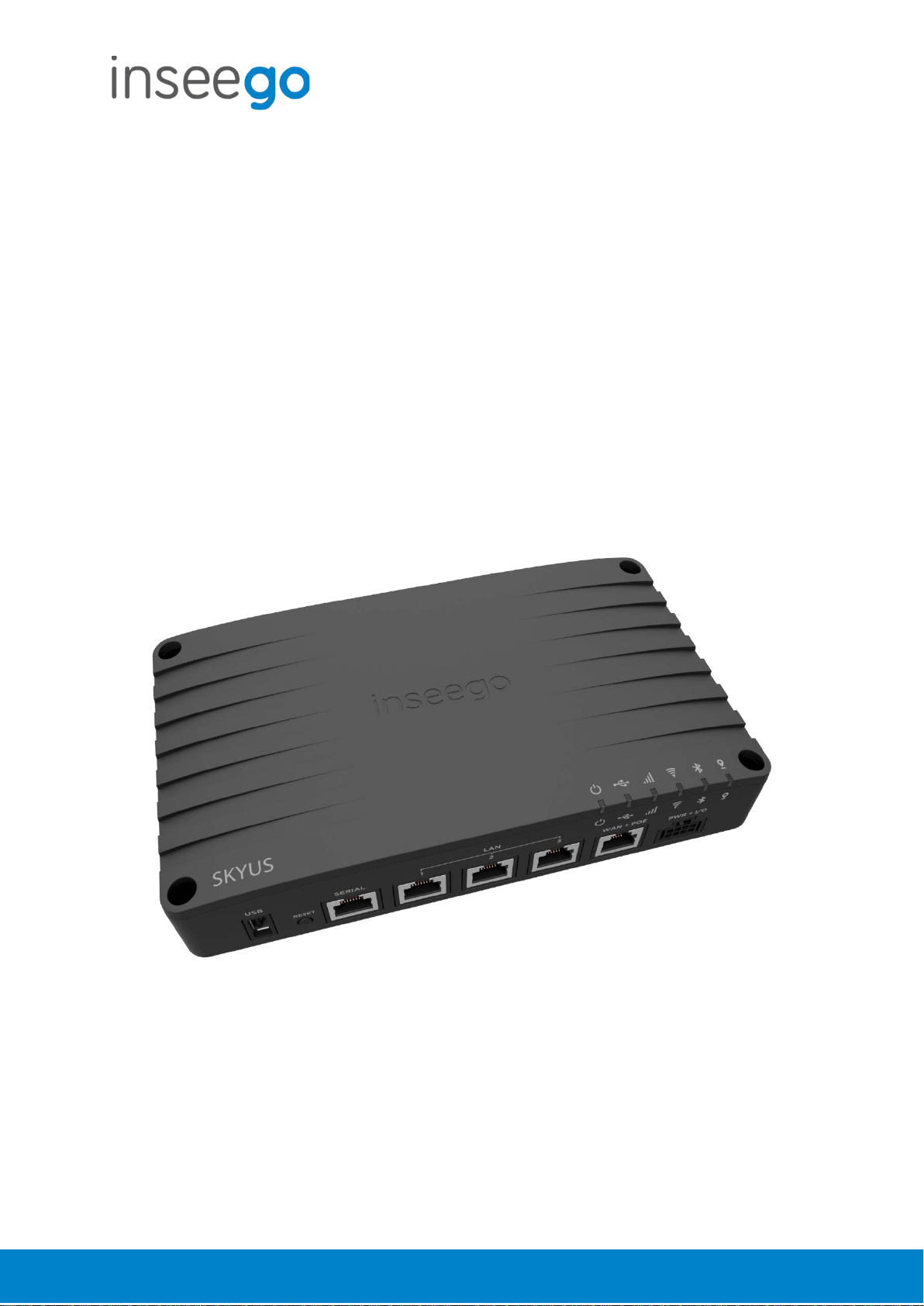
Skyus 500
Inseego
9605 Scranton Road Suite 300
San Diego, CA 92121
(858) 812-3400
Page 2

User Guide
inseego.com
Skyus 500 (Ninkasi)
Table of Contents
1. Product Overview ........................................................................................................................... 3
2. UI Reference.................................................................................................................................... 6
3. Using, Testing, Troubleshooting ................................................................................................... 48
4. Regulatory Information ................................................................................................................. 78
Rev 1 Page 2 of 78
Page 3
User Guide
inseego.com
Skyus 500 (Ninkasi)
1. Product Overview
Marketing Name: Skyus 500V
Model Name: SKR5MD8800
Base SKU: SK500V
Front View
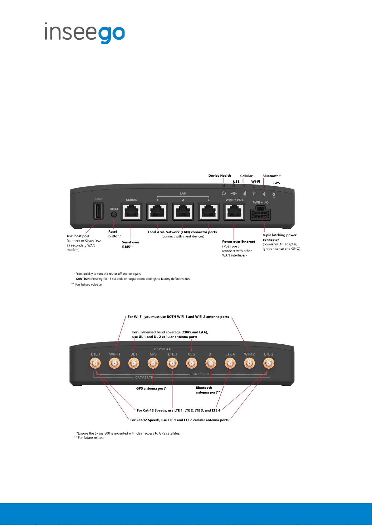
Back View
Rev 1 Page 3 of 78
Page 4
User Guide
inseego.com
Skyus 500 (Ninkasi)
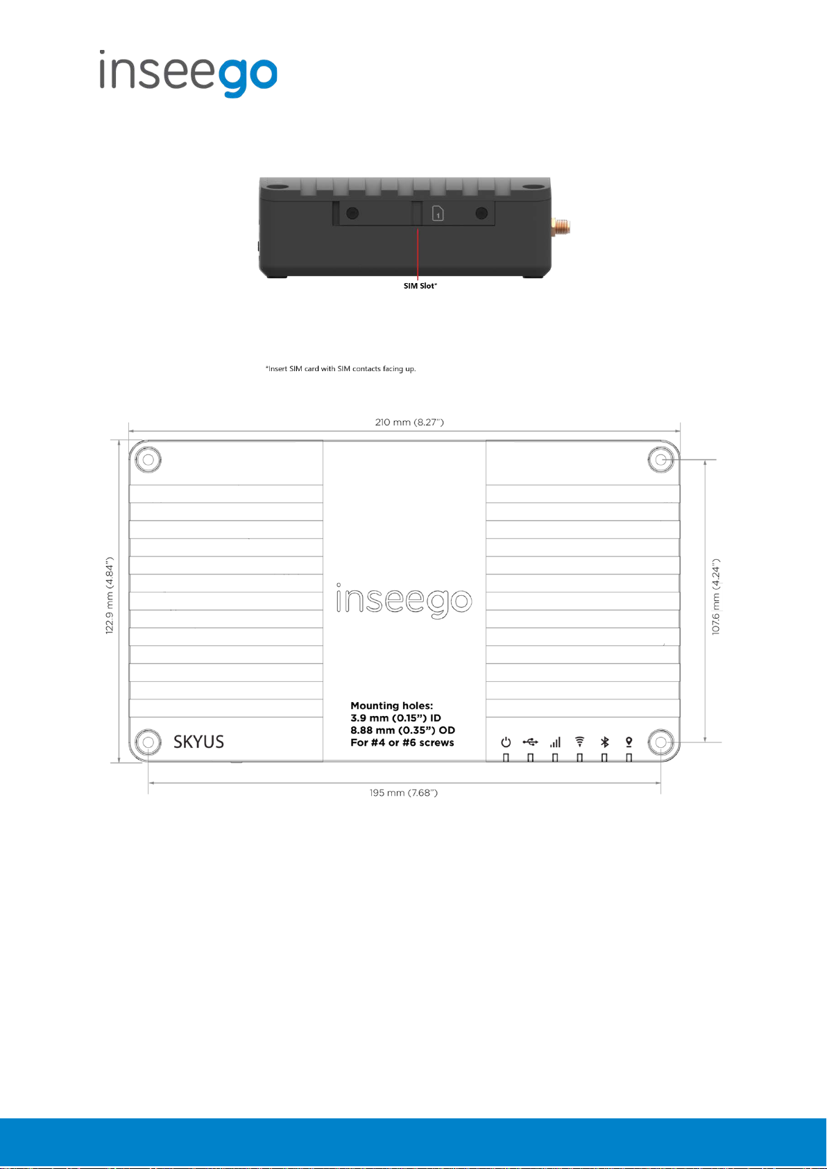
Right Side View
Rev 1 Page 4 of 78
Page 5

User Guide
inseego.com
Device Health
Green
Solid
Good
Orange
Solid
Temperature Approaching Limits
Magenta
Solid
Thermal Protection Mode
Blue
Slow blink
Firmware Update Available
USB
Green
Solid
Connected External Device
Blue
Solid
Fast Blink
External Cellular Device Active (Routing Mode from External
Traffic passing from external modem
Cellular
White
Solid
Slow Blink
No SIM
Inactive SIM
Red
Solid
Cellular Error
Blue
Solid
Excellent Signal
Green
Solid
Great Signal
Yellow
Solid
Good Signal
Orange
Solid
OK Signal
Magenta
Solid
Poor Signal
Wi-Fi
Off
Off
Off
Red
Solid
Wi-Fi Error
White
Solid
On with no Connected Devices
Green
Solid
Fast Blink
On with Connected Devices
Wi-Fi Traffic
Blue
Solid
Fast Blink
Wi-Fi as WAN Mode Active
Traffic passing over Wi-Fi as WAN
Bluetooth*
GPS
Off
Off
Off
Red
Solid
GPS Error
White
Slow Blink
Searching/Acquiring
Yellow
Solid
GPS Active
Skyus 500 (Ninkasi)
Indicator LEDs
The Skyus 500 has six indicator LEDs. These indicators change colors and either blink or glow
solid to communicate current states for the device.
LED LED Color Operation Meaning
Fast Blink
Fast Blink
Fast Blink
Fast Blink
Fast Blink
Device or Failover is Active)
Excellent Signal with Traffic
Great Signal with Traffic
Good Signal with Traffic
OK Signal with Traffic
Poor Signal with Traffic
*For future release
Rev 1 Page 5 of 78
Page 6

User Guide
inseego.com
Skyus 500 (Ninkasi)
2. UI Reference
Navigating the Web UI
Home Page
The Skyus 500 Home page is the local gateway to configuring and managing your router. It
displays current router status, lists currently connected devices, and offers links to other pages
with option settings and help.
Click > in the bottom-right corner of a panel to access subscreens with further information and
options.
Side Menu
Each subscreen in the Skyus 500 Web Interface includes a menu on the left, which you can use to
return to the Home page or jump to other screens. The current screen is indicated by a red bar.
The side menu includes items that are not visible from the Home page, including Access Control,
GPS, GPIO, VPN, and Remote Management. Access a subscreen from the Home page to
choose these additional options from the Side Menu.
Help
Select the question mark (?) in the upper right hand corner of a page to view Help on that topic.
Initial Configuration
There are some initial steps you may want to take before connecting more devices to your Skyus
500.
1. Set up Primary network name, security, and password on the Wi-Fi > Wi-Fi Primary
Network tab. You can also set up a Guest network on the Wi-Fi > Wi-Fi Guest Network tab.
2. Change the Admin password for the Web UI. Click the down arrow next to Sign Out in the
top-right corner of any Web Interface page and select Change Password. Select Help >
Admin Password for more information.
3. To set an Access Point Name (APN) for your network to communicate with the Skyus 500, go
to Settings > Advanced > Network tab.
Connecting Devices
You can connect up to 128 client devices to your Skyus 500 via Wi-Fi. NOTE: This many client
devices may affect throughput and stability.
Connecting via Wi-Fi
To wirelessly connect a Wi-Fi-capable device to your Skyus 500 for the first time:
Rev 1 Page 6 of 78
Page 7

User Guide
inseego.com
Skyus 500 (Ninkasi)
1. On the device you want to connect to the Internet, open the Wi-Fi application or controls
and in the displayed list of available networks, find the network name for your Skyus 500.
2. Click Connect or otherwise select the network name.
3. When prompted, enter the password. NOTE: The Wi-Fi name and password are displayed
in the Wi-Fi panel of the Home screen.
Connecting via Ethernet
To connect a wired device to your Skyus 500, plug the end of an Ethernet cable into one of the
three LAN ports.
Rev 1 Page 7 of 78
Page 8

User Guide
inseego.com
Skyus 500 (Ninkasi)
Support
A User Guide for your Skyus 500 is available online. To download the complete User Guide, go to
www.inseego.com/support-documentation
For additional information and technical support, email Technical Support at
technicalsupportus@inseego.com
or call Customer Support (Toll Free) at 1-877-698-6481.
.
Rev 1 Page 8 of 78
Page 9

User Guide
inseego.com
Skyus 500 (Ninkasi)
Admin Password
The Admin password is what you use to sign into the Skyus 500 Web Interface. Initially, it is the
same as the default password for your router’s Primary network and is printed on the bottom of
the router.
NOTE: You can set up separate Wi-Fi passwords both Primary and Guest networks in Wi-Fi, but
these are different from the Admin password, which is for this Web Interface.
Important: It is critical that you change the Admin password from the default to keep the
device and your network secure.
To change the Admin password, click the down arrow next to Sign Out in the top-right corner of
any Web Interface page and select Change Password. Enter your current Admin password, then
enter a new password and confirm it.
You must also select a security question from the drop-down list and type an answer to question
in the Answer field. NOTE: Answers are case-sensitive. Click Save Changes.
The next time you sign in to the Skyus 500 Web Interface, use the new Admin password. If you
cannot remember the password, click I forgot the Admin password. After you correctly answer
the security question you set up, the current password is displayed.
Rev 1 Page 9 of 78
Page 10

User Guide
inseego.com
Skyus 500 (Ninkasi)
Wi-Fi - Settings
You can use the default values as they appear on this tab, or can adjust them for your
environment.
Wi-Fi
Use the Allow Wi-Fi devices to connect to this Router ON/OFF slider to turn Wi-Fi on or off.
This selection affects Primary and Guest networks.
When Wi-Fi is turned off, the only way to connect to the router (and to the Admin website) is
with Ethernet cable.
Band Selection
Each network can be accessed over two bands: 2.4 GHz and 5 GHz:
• The 2.4 GHz band is supported by all devices with Wi-Fi and should be used by devices
that are a few years old or older. This band passes through walls better, so it may have a
longer range.
• The 5 GHz band is best for newer devices. It offers better throughput and reduced
interference, but does not pass through walls as well as the 2.4 GHz band.
NOTE: The Guest Network must be assigned at least one band before it can be turned on.
2.4 GHz Band Selection
This section displays the 802.11 Mode in use when the 2.4 GHz band is active and allows you to
select a Channel.
NOTE: Leave the Channel set to Automatic unless you need to choose a particular channel for
your environment.
5 GHz Band Selection
This section displays the 802.11 Mode in use when the 5 GHz band is active and allows you to
select a Bandwidth and Channel.
NOTE: Leave the Bandwidth at the default setting unless you experience interference with other
Wi-Fi devices. If you experience interference, try lowering the Bandwidth setting to reduce the
interference.
NOTE: Leave the Channel set to Automatic unless you need to choose a particular channel for
your environment.
Select Save Changes to store new settings.
Rev 1 Page 10 of 78
Page 11

User Guide
inseego.com
Skyus 500 (Ninkasi)
Wi-Fi – Primary Network
Use these settings to connect initially to the Primary Wi-Fi network or change Primary network
information. Connected devices must use the Wi-Fi settings shown on this screen.
NOTE: If you change these settings, existing connected devices may lose their connection.
Settings
Primary network name (SSID): Enter a Primary network name (SSID) to set up or change the
Primary network name. The name can be up to 28 characters long.
Security: Select an option for Wi-Fi security:
• WPA2 Personal is the most secure method of Wi-Fi Protected Access and should be
used if possible.
• WPA/WPA2 Personal can be used if some of your older devices do not support WPA2.
• WPA/WPA2 Enterprise is designed for organizations and includes enterprise-grade
authentication. NOTE: This method provides administrative control over access to your
Wi-Fi network, so that administrators assign, modify and revoke login credentials for
users. A Remote Authentication Dial-In User Service (RADIUS) server is required and must
be configured for this option.
• None allows others to monitor your Wi-Fi traffic and use your data plan to access the
Internet. NOTE: Avoid using this option.
Password: Enter a Wi-Fi password, or you can use the Generate new password button.
Important: It is critical that you change the password from the default and use a different
password from your Admin password to keep the device and your network secure.
Generate new password: This button inserts a strong random password in the Password field.
You can click the eye icon to view the password.
Options
Broadcast primary network name (SSID): Check this box to allow Wi-Fi devices in the area to
see the Wi-Fi Primary network name (SSID) on their list of available networks. If not selected, the
network name will need to be manually entered for devices to connect to the network.
Select Save Changes to store new settings.
Rev 1 Page 11 of 78
Page 12

User Guide
inseego.com
Skyus 500 (Ninkasi)
Wi-Fi – Guest Network
The Wi-Fi Guest network allows you to segregate traffic to a separate network rather than share
access to your Wi-Fi Primary network. Use settings on this tab to set up or change Wi-Fi Guest
network information. Connected devices must use the Wi-Fi settings shown on this screen to
connect to the Guest Wi-Fi network.
NOTE: To turn the Wi-Fi Guest network on, you must select at least one band for Guest Network
under Band Selection on the Wi-Fi Settings tab and then select Save Changes.
Settings
Guest network name (SSID): Enter a Guest network name (SSID) to set up or change the Guest
network name. The name can be up to 28 characters long.
Security: Select an option for Wi-Fi security:
• WPA2 Personal is the most secure method of Wi-Fi Protected Access and should be
used if possible.
• WPA/WPA2 Personal can be used if some of your older devices do not support WPA2.
• WPA/WPA2 Enterprise is designed for organizations and includes enterprise-grade
authentication. NOTE: This method provides administrative control over access to your
Wi-Fi network, so that administrators assign, modify and revoke login credentials for
users. A Remote Authentication Dial-In User Service (RADIUS) server is required and must
be configured for this option.
• None allows others to monitor your Wi-Fi traffic and use your data plan to access the
Internet. NOTE: Avoid using this option.
Password: Enter a Wi-Fi password, or you can use the Generate new password button.
Important: It is critical that you change the password from the default and use a different
password from your Admin or Primary network password to keep the device and your network
secure.
Generate new password: This button inserts a strong random password in the Password field.
You can click the eye icon to view the password.
Options
Broadcast guest network name (SSID): Check this box to allow Wi-Fi devices in the area to see
the Wi-Fi Guest network name (SSID) on their list of available networks. If not selected, the
network name will need to be manually entered for devices to connect to the network.
Select Save Changes to store new settings.
Rev 1 Page 12 of 78
Page 13

User Guide
inseego.com
Skyus 500 (Ninkasi)
Wi-Fi – Wi-Fi as WAN
Use settings on this tab to set options for using an external Wi-Fi network to access the Internet.
NOTE: To enable Wi-Fi as WAN, you must go to the Wi-Fi Settings tab and in Band Selection,
select a band for Wi-Fi as WAN. Then select Save Changes.
Important: Only one station/network from either the 2.4GHz or 5GHz band can be enabled at
a time. If you deselect a band from the Primary or Guest network, some existing connected
devices may lose their connection.
Once you have enabled Wi-Fi as WAN on the Wi-Fi Settings tab, return to the Wi-Fi as WAN tab.
The band you enabled is displayed.
Access Points
By default, one access point is listed initially.
Add Access Point: Use this button to add a hidden network. The Add new access point dialog
displays. Enter an SSID, choose a security level from the Security drop-down, and enter a
password if prompted. Select Save Changes.
Once connected, the new access point appears in the Access Points list.
Scan: Use this button to see a list of available access points and add an access point. The Scan
Results dialog displays, listing available access points. Click Add to add an access point. The Add
new access point dialog displays. Choose a security level from the Security drop-down and
enter a password if prompted. Select Save Changes.
Once connected, the new access point appears in the Access Points list.
When there is at least one Access Point in the Access Points list, you can set the following:
• Enabled: Enable or disable an access point.
• Priority: Use the Up and Down buttons to set the priority for each access point.
If an access point is enabled and available, and has highest priority among the enabled
access points (is first in the list), the Skyus 500 connects to that access point and displays its
details in the Connected Access Point area below, including:
o SSID: The SSID (network name) of the connected access point.
o MAC Address: The MAC Address (unique network identifier).
o Freq: The frequency used by the connected access point.
o Security: The security level.
o WPA State: The Wi-Fi Protected Access state.
• Edit: Change the SSID, security setting, or password for an access point. NOTE: The SSID and
password must match the access point. Only change these fields to match changes in the
actual access point information.
Rev 1 Page 13 of 78
Page 14

User Guide
inseego.com
Skyus 500 (Ninkasi)
• Delete: Delete an access point from the list.
Rev 1 Page 14 of 78
Page 15

User Guide
inseego.com
Skyus 500 (Ninkasi)
Connected Devices
This page provides details about each device connected to the Skyus 500 and allows you to edit
how device names appear in the Web UI. You can also block or unblock a device from Internet
access.
NOTE: You can also see list of all devices currently connected to the router and the network they
are using in the Connected Devices panel on the Web UI Home page.
Connected
This table lists all devices connected to the Skyus 500:
Connection: An icon indicates the connection type (Wi-Fi or Ethernet) for each device.
(You can hover over the icon to read the type of connection.)
Device: This is usually the hostname set on the connected device. In rare cases, the
hostname may be unavailable.
You can change the name of a device as it appears in the Skyus 500 Web UI by clicking in
the Device field and editing the name. NOTE: This only changes the how the device
name appears in the Skyus 500 Web UI.
Network: Indicates whether the device is connected to the Primary or Guest network.
Block: Select this box to disconnect a device and prevent it from reconnecting. Select
Save Changes. The device is removed from the Connected list and appears in the
Blocked list below.
NOTE: This option is available for each device connected through Wi-Fi, but is not
available for your own device or devices connected via Ethernet.
To view details on a device, click the plus icon (+) on the right to expand the device row. The
following information appears:
• IP Address: The IP address of the connected device.
• MAC Address: The MAC Address (unique network identifier for this connected device).
• Link Local: The Link-Local IPv6 address if the connected device supports IPv6.
Click the minus icon (-) to collapse a row.
Blocked
This section lists all devices blocked from connecting to the Skyus 500.
NOTE: Since blocked devices are not currently connected, they do not have an IP address.
Instead, they are identified by their name and MAC address.
To unblock a blocked device, click the Unblock button and select Save Changes. The device is
removed from the Blocked list and appears in the Connected list above.
Rev 1 Page 15 of 78
Page 16

User Guide
inseego.com
Skyus 500 (Ninkasi)
Rev 1 Page 16 of 78
Page 17

User Guide
inseego.com
Skyus 500 (Ninkasi)
Access Control - Devices
Access controls in the Skyus 500 Web UI allow you to control Internet access to specific devices.
You can set up multiple schedules for Internet access on the Schedules tab and apply them to
individual connected devices on the Devices tab.
NOTE: You must first create schedules on the Schedules tab for device and schedule information
to display on the Devices tab.
This tab lists all currently connected devices and any applied schedules. (Unspecified indicates
that no schedule is applied to a device, and Internet access is unrestricted.)
To apply a schedule to a device, select a schedule from the drop-down list. Select Save Changes.
Rev 1 Page 17 of 78
Page 18

User Guide
inseego.com
Skyus 500 (Ninkasi)
Access Control - Schedules
Access controls in the Skyus 500 Web UI allow you to control Internet access to specific devices.
You can set up multiple schedules for Internet access on the Schedules tab and apply them to
individual connected devices on the Devices tab.
Use this tab to manage schedules for when devices can access the Internet through the Skyus
500.
Create New Schedule: Select this button to create a new schedule. The Create New Schedule
dialog box appears. Enter a name and description for the schedule.
In the Access section:
• Determine if you want Allow access during the specified days/times or if you want to
Block access during the specified days/times.
• Set a range of time for allowing or blocking Internet access:
o Select the days of the week you want the range to apply to.
o Enter start and end times for the range.
Select Save Schedule to close the dialog box and return to the Schedules page. The new
schedule is now listed.
Use the View, Edit, and Delete buttons to view, edit, or delete (unapplied schedules only) listed
schedules.
Use the Devices tab to apply schedules to devices.
Rev 1 Page 18 of 78
Page 19

User Guide
inseego.com
Skyus 500 (Ninkasi)
Settings - Preferences
This tab allows you to change how dates, time, and numbers are displayed in the Skyus 500 Web
UI. NOTE: These preferences affect packets sent to remote servers. For example, if you select a 24
hour time format, the Web UI, and any packets reporting time somewhere else, will display time
in 24 hour format.
Date: Select the date format to be used throughout the Web UI and remote servers
(mm/dd/yyyy or dd/mm/yyyy).
Time: Select the time format to be used throughout the Web UI and remote servers (12 or 24
hour).
Number Format: Choose the format for decimal numbers displayed in the Web UI and remote
servers (using a period or comma as the decimal point).
Select your display choices from the drop-down menus and click Save Changes to update
settings.
Rev 1 Page 19 of 78
Page 20

User Guide
inseego.com
Skyus 500 (Ninkasi)
Settings – Software Update
Software updates are delivered to the Skyus 500 automatically over the mobile network. This tab
displays your current software version, last system update information, and allows you to check
for new software updates.
NOTE: You can also view the date and time of the last system update in the Settings panel on the
Web UI Home page.
Current Software
Software Version: The version of the software currently installed on your Skyus 500.
Check for New System Update
Checked for update: The date and time the Skyus 500 last checked to see if an update was
available.
Update status: This is area is usually blank. If you check for an update, the result of that check, or
the download progress of an update displays.
Check for update: Click this button to manually check for available software updates.
• If a new software update is available, click Download now to install it.
• If a new system update is available, you are given an option to install it now or later.
• If a configuration update is available, it is installed automatically.
Last System Update
This section displays details about the last software update.
System Update History
This section displays details of the last updates that have been downloaded and installed to this
device. If this section is blank, no updates have been installed.
Rev 1 Page 20 of 78
Page 21

User Guide
inseego.com
Skyus 500 (Ninkasi)
Settings – Backup and Restore
Use this tab to back up current Skyus 500 settings to a file on your computer, restore (upload) a
previously-saved configuration file, reset the router to factory defaults, or restart the router.
Backup
To back up current Skyus 500 settings to a file on your computer, enter your Admin password in
the Admin password field.
The default Admin password is printed on the bottom of the router. If you have changed the
Admin password and don’t remember it, select Sign Out in the top-right corner of the Home
page, click I forgot the Admin password, and answer the displayed security question. The
current Admin password will be displayed.
NOTE: If you enter an incorrect password five times in a row, you will be locked out of the Web
UI. To unlock it, restart the router.
Click the Download button. The file is automatically downloaded to your Downloads folder. This
configuration file contains all settings for the device, router and system functions. It does not
contain any modem settings or data.
NOTE: The backup file cannot be edited or viewed on the downloaded system or on any other
device. This file can only be restored for this model of Skyus 500, and settings can only be viewed
or changed using the Web UI.
Restore Settings
CAUTION: Restoring settings (uploading a configuration file) changes ALL of the existing settings
to match the configuration file. This may change the current Wi-Fi settings, breaking all existing
connections to this router and disconnecting you from the Web UI.
To restore system settings from a backup settings file, enter your Admin password in the Admin
password field.
In the Select a file field, click Browse and choose a backup settings file to restore.
NOTE: You can only restore a file that was created for this model of Skyus 500.
Click the Restore Now button.
Restore to Factory Defaults
Restore Factory Defaults: This button resets all settings to their factory default values.
CAUTION: This initiates a restart and may change the current Wi-Fi settings, breaking all existing
connections to this router and disconnecting you from the Web UI.
Rev 1 Page 21 of 78
Page 22

User Guide
inseego.com
Skyus 500 (Ninkasi)
Restart Router
Restart: This button turns your router off and on again.
Rev 1 Page 22 of 78
Page 23

User Guide
inseego.com
Skyus 500 (Ninkasi)
Advanced Features – Lan
This tab provides settings and information about the Skyus 500's local area network (LAN). For
this device, the LAN consists of this device and all Wi-Fi and Ethernet connected devices.
IPv4
IP Address: The IP address for this device, as seen from the local network. Normally, you can use
the default value.
Subnet Mask: The subnet mask network setting for the Skyus 500. The default value
255.255.255.0 is standard for small (class "C") networks. If you change the LAN IP Address, make
sure to use the correct Subnet Mask for the IP address range of the LAN IP address.
MAC Address: (read-only) The Media Access Controller (MAC) Address for the Wi-Fi and USB
interfaces on this device. The MAC address is a unique network identifier assigned when a
network device is manufactured.
Turn on DHCP server: This checkbox turns the DHCP Server feature on or off. This should be left
checked. The DHCP server allocates an IP address to each connected device. NOTE: If the DHCP
Server is turned off, each connected device must be assigned a fixed IP address.
DHCP lease time: The number of minutes in which connected devices must renew the IP address
assigned to them by the DHCP server. Normally, this can be left at the default value, but if you
have special requirements, you can change this value.
Start DHCP address range at: The start of the IP address range used by the DHCP server. If
using a fixed IP address on a connected device, use an IP address outside of this range. NOTE:
Only expert users should change this setting.
End DHCP address range at: The end of the IP address range used by the DHCP server. If using
a fixed IP address on a connected device, use an IP address outside of this range. NOTE: Only
expert users should change this setting.
Use Reserved IP Addresses: This allows you to ensure that a connected device will always be
allocated the same IP Address by the Skyus 500. To use this feature, click the Reserve specific IP
addresses for selected devices link. A list of devices with their MAC Address, Current IP Address,
and a field to enter a Reserved IP Address appears.
Click Save Changes to activate and save new settings.
Rev 1 Page 23 of 78
Page 24

User Guide
inseego.com
Skyus 500 (Ninkasi)
Advanced Features – Network
In most configurations, the Skyus 500 is used with a dynamic IP and SIM and the Access Point
Name (APN) is available from the network, for example: vzwinternet. However, if you are on a
private network, you may need to set the APN on this tab for the network to communicate with
the Skyus 500, for example: we01.vzwstatic.
APN
Internal Modem: Enter the APN for your private network.
CAUTION: Changing the internal modem APN may cause a loss of data connectivity and
disconnect you from the Web UI.
Click Save APN Changes. The router will reboot for changes to take effect.
External Modem: This option is configurable if you have a Skyus DS2 connected to the external
USB port of your Skyus 500. In this case, enter the APN for your private network.
CAUTION: Changing the external modem APN may cause a loss of data connectivity and
disconnect you from the Web UI.
Click Save APN Changes. The router will reboot for changes to take effect.
Rev 1 Page 24 of 78
Page 25

User Guide
inseego.com
Skyus 500 (Ninkasi)
Advanced Features – Manual DNS
The Skyus 500 automatically selects a Domain Name Server (DNS). This tab allows you to
manually assign up to two DNS IP addresses.
Turn on manual DNS: Check this box to manually select a DNS.
DNS 1 IP address: Enter the IP address for the primary DNS. This address is required to use the
Manual DNS feature.
DNS 2 IP address: Enter the IP address for the secondary (backup) DNS. This address is optional
and may be left blank if desired.
Click Save Changes.
Rev 1 Page 25 of 78
Page 26

User Guide
inseego.com
Skyus 500 (Ninkasi)
Advanced Features – Firewall
The Skyus 500 firewall determines which Internet traffic is allowed to pass between the router
and connected devices and protects your connected devices from malicious incoming traffic from
the Internet. The firewall cannot be turned off.
Use the Firewall tab to adjust the general security level of the firewall, designate a specific device
to receive all traffic, and set up specific firewall rules.
Security Level
You can select from three general security levels to block traffic into and through the Skyus 500.
The default Security Level is Medium.
• Low — allows inbound traffic to services with open ports matching the inbound request
port. Outbound traffic is allowed to any service.
• Medium — Rejects inbound traffic. Outbound traffic is allowed for any service.
• High — Rejects inbound traffic. Outbound traffic is allowed only for TELNET (port 23), FTP
(port 21), HTTP (port 21), HTTP (port 80), HTTPS (port 443), SMTP (port 25), DNS (port 53),
POP3 (port 110), and IMAP (port 143).
DMZ
DMZ allows the connected device specified as the DMZ IP address (the DMZ destination) to
receive all traffic that would otherwise be blocked by the firewall.
NOTE: Allowing DMZ may assist some troublesome network applications to function properly,
but the DMZ device should have its own firewall to protect itself against malicious traffic.
Allow DMZ: Check this box to allow DMZ.
Destination IP Address: Enter the IP address of the connected device you wish to become the
DMZ device (the DMZ destination). NOTE: You can check the IP address of each connected
device on the Connected Devices screen.
Click Save Changes.
Firewall Rules
You can define one or more specific rules for the firewall to follow. Use the fields to set up a rule,
and click Add New Rule. New rules are added to the bottom of the list. Use Up and Down to
reposition rules on the list.
NOTE: For Src. IP and Dest. IP, enter a specific IP address or the keyword any.
Rev 1 Page 26 of 78
Page 27

User Guide
inseego.com
Skyus 500 (Ninkasi)
Advanced Features – MAC Filter
The MAC filter allows only selected devices to access the Skyus 500’s Primary Wi-Fi network. By
default, MAC filter is turned OFF.
Use this tab to turn the MAC Filter ON and specify device access.
NOTE: The MAC filter has no effect on devices connected to the Guest Wi-Fi network or
connected via Ethernet.
MAC Filter
To use the MAC filter, select the device(s) from the device list that you want to be allowed to
connect to the Primary network and move the ON/OFF slider to ON.
CAUTION: Turning on MAC filtering immediately disconnects all devices that are not included in
the filter from the Primary network.
Device List
This list includes all devices currently connected to the Skyus 500, except those connected via
Ethernet.
Add new device: Use this button to add a device to the device list, then enter the device name,
MAC address, choose whether to select the MAC Address Filter checkbox, and click Save
Changes.
To delete a device from the list, select its Delete checkbox and click Save Changes.
To discard any unsaved changes and refresh the list, click Refresh List.
Notes on Blocking Devices
There are two ways to block devices from connecting to the Skyus 500:
• Temporarily block a device from connecting to the router via the Primary and Guest
networks and via Ethernet.
To use this method, go to the Connected Devices page and click the Block button next
to the device.
• Permanently block a device from connecting to your router’s Primary network only.
Use the MAC Filter.
When blocking devices, the following information applies:
• Devices blocked with Connected Devices > Block are blocked from the Wi-Fi network,
even if the MAC Filter is ON and the device is enabled for the MAC Filter.
Rev 1 Page 27 of 78
Page 28

User Guide
inseego.com
Skyus 500 (Ninkasi)
• If the MAC Filter is ON, and a device is blocked with Connected Devices > Block, and is
not enabled for the MAC Filter, then it will not be able to connect. Both the MAC Filter
and the Block prevent connection.
• If the MAC Filter is ON, and a device is enabled for the MAC Filter, then the device will be
able to connect. However, it can still be blocked using Connected Devices > Block or by
disabling the MAC Filter.
Rev 1 Page 28 of 78
Page 29

User Guide
inseego.com
Skyus 500 (Ninkasi)
Advanced Features – Port Filtering
Port Filtering allows you to block outgoing Internet connections and permit only selected
applications to access the Internet. Traffic is identified by port numbers. Some applications are
pre-defined. You can define additional applications if you know the details of the traffic used and
generated by the applications.
NOTE: You can view the current Port Filtering setting (ON/OFF) in the Settings panel on the Web
UI Home page.
Port Filtering
To turn on port filtering, move the ON/OFF slider to ON.
To turn off port filtering, so that any application can connect to the Internet, move the slider to
OFF.
Applications
Select the applications you want to be able to access the Internet and click Save Changes.
Custom Applications
You can define up to ten custom applications.
Add custom application: Use this button to add a new row to the custom application list.
• On: Check this box if you want the new application to be able to access the Internet.
• Application Name: Enter a name for the custom application.
• Start Port: Enter the beginning of the range of port numbers used by outgoing traffic for
the custom application being added.
• End Port: Enter the end of the range of port numbers used by the application.
• NOTE: If the application uses a single port instead of a range, type the same value for
both the Start Port and the End Port.
• Protocol: Select the protocol used by the port range from the drop-down list (TCP, UDP,
or both).
• Delete: Check this box to delete a custom application. NOTE: Click on the Port Filtering
tab again to remove deleted custom applications from view on the screen.
Click Save Changes to save any changes made to the custom applications.
Rev 1 Page 29 of 78
Page 30

User Guide
inseego.com
Skyus 500 (Ninkasi)
Advanced Features – Port Forwarding
Port Forwarding allows incoming traffic from the Internet to be forwarded to a particular
computer or device on your Wi-Fi network. Normally, the built-in firewall blocks incoming traffic
from the Internet. Port forwarding allows Internet users to access any server you are running on
your computer, such as a Web, FTP, or Email server. For some online games, port forwarding
must be used in order for the games to function correctly.
IMPORTANT: Port forwarding creates a security risk and should not be turned on unless it is
required.
Some mobile networks provide you with an IP address on their own network rather than an
Internet IP address. In this case, Port Forwarding cannot be used, because Internet users cannot
reach your IP address.
Port Forwarding
To turn on port forwarding, move the ON/OFF slider to ON.
To turn off port forwarding, so that any application can connect to the Internet, move the slider
to OFF.
Port Forwarding Applications
Check the box next to each Port Forwarding application that you want to allow.
If you want to limit service for an application to a single connected device, enter the IP address of
the target device in the application’s IP Address field.
Click Save Changes.
Custom Applications
You can add up to ten custom applications. Once defined, these applications can be turned on
and off the same way as pre-defined applications.
Add Custom Application: Use this button to add a new row to the custom applications list.
• On: Check this box if you want the application to be able to access the Internet.
• Application Name: Enter a name for the custom application.
• IP Address: If you want to limit service for the application to a single connected device,
enter the IP address of the target device. To find the IP address of a device, go to the
Connected Devices page.
• Port Type: Select Range or Translate from the drop-down list.
Rev 1 Page 30 of 78
Page 31

User Guide
inseego.com
Skyus 500 (Ninkasi)
• Port Numbers: Use the From and To fields to specify the range of port numbers used by
outgoing traffic for the custom application. NOTE: If the application uses a single port
instead of a range, type the same value in both the From and To fields.
For translate ports, use the Ext. and Int. to specify ports.
• Protocol: Select the protocol used by the port range from the drop-down list (TCP, UDP,
or both).
• Delete: Check this box to delete a custom application. NOTE: Click on the Port
Forwarding tab again to remove deleted custom applications from view on the screen.
Click Save Changes to save any changes made to the custom applications.
Rev 1 Page 31 of 78
Page 32

User Guide
inseego.com
Skyus 500 (Ninkasi)
Advanced Features – WAN Configuration
Use this tab to configure and set the priority of each available WAN interface.
Active WAN Interface
This section displays current active WAN interfaces.
Priority Listing of the Available WAN Interfaces
Use the drop-downs to reset the priorities you wish for WAN interfaces.
WAN Settings
Use the tabs to set the following for each WAN interface.
• WAN interval — How often the router verifies a connection on this interface, in minutes.
NOTE: A shorter interval will use more router resources and more data, while a longer
interval may delay detection of issues.
• WAN ICMP host 1 — The IP address of the host. This must be a stable Internet address.
• WAN ICMP host 2 — The IP address of the host. This must be a stable Internet address.
• WAN ICMP host 3 — The IP address of the host. This must be a stable Internet address.
• WAN timeout — The amount of time the router waits between verification attempts, in
minutes, before determining the verification has failed. NOTE: A shorter amount of time
may create false positive results, while a longer amount of time may delay detection of
issues.
• WAN retries — The number of times the router attempts to verify the connection on this
interface before the connection is considered failed. NOTE: A smaller value may create
false positive results, while a larger value may delay detection of issues.
• WAN recovery retries — The number of successful checks a failed connection requires
before it is considered active again.
Rev 1 Page 32 of 78
Page 33

User Guide
inseego.com
Skyus 500 (Ninkasi)
GPS - Status
The Skyus 500 incorporates a GPS receiver. The GPS receiver can determine your current location,
often even indoors. Current location information can be shared with connected devices by using
the Local Streaming feature on the Local tab.
Use settings on this tab to enable or disable GPS and to view the current status of your GPS
connection.
Enable GPS Receiver
This setting enables or disables the GPS radio on your device. When the ON/OFF slider is ON, the
device acquires GPS and makes the data available to applications running on the device. When
OFF, no GPS data is available.
Status: The current status of your GPS connection. When searching, the device is making the
connection to satellites in order to populate GPS data.
Latitude: Latitude for the last location fix.
Longitude: Longitude for the last location fix.
Speed: Speed the device is traveling at.
Altitude: Altitude for the last location fix.
Accuracy: A measure of the accuracy of the horizontal position obtained by the GPS receiver.
Direction: Direction of North relative to the direction the device is traveling.
Rev 1 Page 33 of 78
Page 34

User Guide
inseego.com
Skyus 500 (Ninkasi)
GPS - Local
GPS data is provided by the Skyus 500 in the form of a National Marine Electronics Association
(NMEA) text stream. Using a NMEA (GPS) port is a standard method for applications to access a
GPS data stream in Windows and other computing platforms.
To create this port, you must download and install the GPS over Wi-Fi driver for your platform.
This driver will create the NMEA port, obtain GPS data from the Skyus 500, and make this GPS
data available to NMEA-aware applications.
Once you have created the port, use this tab to turn on Local GPS.
Turn on local GPS: Check this box to turn on local GPS.
Port Number: The port number used by the driver software on your computer to establish a
connection to the Skyus 500 and obtain GPS data. Unless there is a good reason to do so, you
should not change the port number. Acceptable port values are between 1024 and 65535.
Click Save Changes to update settings.
Rev 1 Page 34 of 78
Page 35

User Guide
inseego.com
Skyus 500 (Ninkasi)
http://192.168.0.1/cgi-bin/luci/vzw/gps/gps_remote
(rewrite – Replace all text)
GPS - Remote
Use this tab to configure the system to stream GPS data to remote servers. NOTE: These servers
are not IoT Connect. Use the Remote Management page to configure IoT Connect remote
servers.
Global device ID: The 4-digit unique ID specific to your Skyus 500 that is inserted into your GPS
packet for routing to remote servers.
GPS Remote Server Configurations
Add remote server: Use this button to add a remote server. The Add GPS Remote Server
dialog appears with the following options:
• Server name — Enter a name for the GPS remote server.
• Odometer value — If you want to utilize this feature, input the current Odometer
reading from your vehicle. Once set, the Skyus 500 will monitor distance traveled and add
to this value. For example, if you set this to 0 and you drive 10 miles, the value will be 10;
if you set this to 100 and drive 10 miles, the value will be 110. NOTE: You can only set
one odometer value, which will serve as the value for all GPS remote servers.
• Report current odometer value — You have the option to track this data, but not report
it to remote servers in order to save data usage. If this box is un-checked, the device will
not report the odometer value to remote servers.
GPS Report Server
• Reporting— To begin streaming GPS data from your Skyus 500 to the remote server,
check this box.
• Store and forward — If there is an interruption in the WAN interface, the system can
store packets and forward them once the WAN interface connection returns. Check this
box if you want the system to store and forward packets.
• Server address — Enter the address for the remote server to which you would like to
route packets.
• Port Number — Enter the port for the remote server to which you would like to route
packets. Acceptable port values are between 1024 and 65535.
• Network protocol — Select the protocol to use for routing packets to your remote serve
from the drop-down (TCP or UDP).
NMEA/TAIP Reporting
The Skyus 500 is capable of routing NMEA or TAIP sentences to the remote server.
Rev 1 Page 35 of 78
Page 36

User Guide
inseego.com
Skyus 500 (Ninkasi)
Select NMEA or TAIP. The available options for your selection are displayed. Select or de-select
any option. All options that are checked will be part of the packet routed to the remote server.
Reporting Triggers
• Time Interval — You can set a time interval to trigger when packets will be routed to the
remote server. For example, if you select 15 minutes, a GPS packet will be sent to the
remote server 15 every minutes.
Check the box if you want to use the time interval and enter a value between 5 and 60
minutes.
• Distance Interval — You can set a distance interval to trigger when packets will be
routed to the remote server. For example, if you select 1000 feet, a GPS packet will be
sent to the remote server every time your device moves 1000 feet.
Check the box if you want to use the distance interval and enter a value between 130 and
215009 feet.
NOTE: You can choose both Time and Distance as your interval specification. The device
will route packets based on which event occurs first.
• Stationary Timer — You can set a stationary timer that monitors for movement and only
route packets if the Skyus 500 is continuously moving within the time range. For example,
if you set this value to 1 minute and your router has not moved within 1 minute, a packet
will not be routed. Once your device begins registering GPS movement again, packet
routing will resume.
Check the box if you want to use the stationary timer and enter a value between 60 and
15300 seconds.
Click Save Changes to implement your settings or Cancel to cancel. You return to the Remote
page. The new remote server is now listed.
Use the View, Edit, and Delete buttons to view, edit, or delete listed remote servers.
Rev 1 Page 36 of 78
Page 37

User Guide
inseego.com
Skyus 500 (Ninkasi)
http://192.168.0.1/cgi-bin/luci/vzw/gpio
(new content – Replace all text)
GPIO
The Skyus 500 includes General Purpose Input Output (GPIO) ignition sense. This feature detects
when the ignition is on and automatically turns on the router. When the ignition is turned off, the
router turns off with a specified time delay.
Use settings on this tab to enable or disable ignition sense, define a time delay, and configure or
view pin settings.
NOTE: When using Skyus 500 in vehicles, enable ignition sense to ensure a controlled shutdown
of the router when the vehicle is turned off.
Ignition Sense
Ignition Sense Enabled: This setting enables or disables ignition sense on your Skyus 500. Check
the box if you want the Skyus 500 to turn on and off (with time delay) with the ignition.
Ignition Sense Delay: If ignition sense is enabled, you can set the amount of time (in seconds) you
want the router to remain on after the ignition is turned off.
GPIO Control
In this section you can configure two digital pins for Input (for sensors) or Output (to devices).
You can see the state of the pin and pulse count (for Input) and set Output to Low or Off.
GPIO #1 State: Select INPUT or OUTPUT.
Value: The state specified by the pin: Low or High.
Pulse Count (visible for INPUT): Displays the number of times the Value field has moved from Low
to High or High to Low. NOTE: To reset the pulse count to zero, reset the device to the factory
default settings.
GPIO #2 State: Select INPUT or OUTPUT.
Value: The state specified by the pin: Low or High.
Set Output (visible for OUTPUT): Select Active Low (ON) or OFF from the drop-down.
External Pins
This section displays settings for dedicated Input and Output pins.
Dedicated Input Pin
Value: The state specified by the pin: Low or High.
Rev 1 Page 37 of 78
Page 38

User Guide
inseego.com
Skyus 500 (Ninkasi)
Pulse Count: The number of times the Value field has moved from Low to High or High to Low.
NOTE: To reset the pulse count to zero, reset the device to the factory default settings.
Dedicated Output Pin
Value: The state specified by the pin: Low or High.
Set Output: The output specified by the pin: Active Low or OFF.
Rev 1 Page 38 of 78
Page 39

User Guide
inseego.com
Skyus 500 (Ninkasi)
VPN
The Skyus 500 allows you to create IPSEC VPNs to establish secure connections to remote
networks over a public network.
VPN Service
This setting enables or disables IPSEC VPN service on your device. When the ON/OFF slider is
ON, VPN is enabled. When OFF, VPN service is not available.
VPN Tunnel Configurations
Once such a tunnel is added, the page would display the list of tunnel configurations.
Administrator can delete, edit, view, change priorities of the tunnel configurations.
Add new VPN Tunnel: Use this button to add a new VPN tunnel. The Add New VPN Tunnel
Dialog appears:
Add New VPN Tunnel: Step 1 out of 5
General Settings
• Start Tunnel — Select whether to start the tunnel automatically upon start up or
manually.
• Enable Tunnel —Check this box to enable the tunnel.
• Tunnel Name — Enter a unique name to identify this VPN.
• Local identity — Enter a unique name to identify the local point of the tunnel.
• Remote identity — Enter a unique name to identify the remote point of the tunnel.
• Local Authentication — Select Pre-shared Key from the drop-down list. This is currently
the only form of authentication available with Skyus 500.
• Pre-shared key — Enter a password used to authenticate to your end of the tunnel
(usually matches the remote password.)
• Remote Authentication — Select Pre-shared Key from the drop-down list. This is
currently the only form of authentication available with Skyus 500.
• Pre-shared key — Enter a password used to authenticate the remote end of the tunnel
(usually matches the local password).
Add New VPN Tunnel: Step 2 out of 5
Local Network
Rev 1 Page 39 of 78
Page 40

User Guide
inseego.com
Skyus 500 (Ninkasi)
• Local IP — Enter the WAN IP address of local device. NOTE: This should be a static IP that
you are able to reach from remote device (no NAT).
• Local Subnet Mask — Enter the subnet mask of the local device, for example: If your
local IP is 192.168.0.100 and your subnet mask is 255.255.255.0 this should be
192.168.0.0/24
for example: 192.168.0.0 / 255.255.255.0. NOTE: The local device should be on a different
subnet from remote, for example: If the Remote Subnet Mask is
Local Subnet Mask might be 192.168.0.0/24. This is usually based off the DHCP settings
of the devices.
. NOTE: This should mirror what the subnet displays in the local device,
192.168.1.0/24, the
Remote Network
• Remote IP — Enter the WAN IP address of remote device. NOTE: This should be a static IP
that you are able to reach from local device (no NAT).
• Remote Subnet Mask — Enter the subnet mask of the remote device, for example: If
your remote IP is 192.168.0.100 and your subnet mask is 255.255.255.0 this should be
192.168.0.0/24
for example: 192.168.0.0 / 255.255.255.0. NOTE: The remote device should be on a
different subnet from local, for example: If the Local Subnet Mask is
Remote Subnet Mask might be 192.168.0.0/24. This is usually based off the DHCP
settings of the devices.
. NOTE: This should mirror what the subnet displays in the local device,
192.168.1.0/24, the
Add New VPN Tunnel: Step 3 out of 5
IKE Phase 1
Select desired items from each column.
NOTE: Each phase should support at least one matching option in each column. For example, if
Phase 1 on this page is configured to support Hash SHA2 512, SHA2 384, and SHA2 256, then at
least one of those selections must be selected in Phase 2 on the next page in order for there to
be a common Hash.
Add New VPN Tunnel: Step 4 out of 5
IKE Phase 2
Select desired items from each column.
NOTE: Each phase should support at least one matching option in each column. For example, if
Phase 1 on the previous page is configured to support Hash SHA2 512, SHA2 384, and SHA2 256,
then at least one of those selections must be selected in Phase 2 on the this page in order for
there to be a common Hash.
Rev 1 Page 40 of 78
Page 41

User Guide
inseego.com
Skyus 500 (Ninkasi)
Add New VPN Tunnel: Step 5 out of 5
Dead Peer Detection (DPD) is a keep-alive method that ensures the tunnel is up and will take
action if it is not able to reach the remote side of the tunnel, depending on what DPD action you
select. You can use the default values, if desired.
Dead Peer Detection
Enable: Check this box to enable DPD.
DPD Action: Use the drop-down to select a DPD action.
DPD Delay: The number of seconds between DPD packets.
DPD Timeout: The number of seconds the router will allow an IPsec session to be idle before
beginning to send DPD packets to the peer machine.
Rev 1 Page 41 of 78
Page 42

User Guide
inseego.com
Skyus 500 (Ninkasi)
Remote Management
Use this tab to enable server reporting with IoT ConnectTM. IoT Connect is a cloud platform
product that provides 360 degree visibility and secure accessibility into your deployment from a
single platform. You must have this product installed to use the Remote Management feature.
Enable IoT Connect Server Reporting: This setting enables or disables server reporting with IoT
Connect on your device.
Remote Server
Connection State: A report on your router’s connection to the IoT Connect server. Up indicates
Skyus 500 is communicating with IoT Servers. Down means Skyus 500 is not communicating with
IoT Connect servers.
Last Reported: The time when your router last sent a packet to the IoT Connect servers.
Configurations
Verbose reporting: Check this box to utilize verbose reporting. This shrinks the size of the
packets your router sends to IoT Connect. You will still be able to use Connection Up or Down,
data usage measurements, alarms, and commands.
Name: This static value shows that this server configuration is for IoT Connect services. NOTE:
Editing this field can affect your ability to utilize IoT Connect services.
Server URL: The server your router is communicating with. This must be the URL where your
router is registered.
Server Port: This static value is provided to show which port your router is using for
communication with IoT Connect.
Server Password: The password that was used to register your Skyus 500. NOTE: Editing this
field can affect your ability to utilize IoT Connect services.
Traffic Type: This static value is provided to show that the router is communicating via Inseego's
protocol.
Exclude GPS: Check this box if you do not want the Skyus 500 to send GPS information to the
IoT Connect server.
Reporting Interval: This is the interval at which your device will send packets into the IoT
Connect server.
Rev 1 Page 42 of 78
Page 43

User Guide
inseego.com
Skyus 500 (Ninkasi)
About – General Status
Use the General Status tab to view general Internet connection and system information.
NOTE: You can also view the Internet status, network, and time connected in the About panel on
the Web UI Home page.
General
• Connection Status: Indicates whether your router is connected to WAN.
• Session Connection Time: The amount of time that has elapsed since the connection for
the current Internet session was established.
• Active Interface: The WAN interface that is active (Ethernet WAN, Primary WAN, Wi-Fi as
WAN, or None).
• Session Data Tx: The amount of data transmitted for the current Internet session. This
counter starts at zero when the connection is established.
• Session Data Rx: The amount of data received for the current Internet session. This
counter starts at zero when the connection is established.
System
• Manufacturer: The manufacturer of this router.
• Model Name: The model name for this device.
• Model Number: The model number for this device.
• Model Version: For the 4G modem component, this is the version of the firmware
(software) currently installed.
• System Version: The version of currently installed software.
Rev 1 Page 43 of 78
Page 44

User Guide
inseego.com
Skyus 500 (Ninkasi)
About – Primary WAN
Use this tab to view details about your Primary WAN connection.
General
• Radio Access Technology: Indicates whether your router is connected to 4G or 4G LTE
or any network.
• IMEI: The International Mobile Equipment Identity (IMEI) for this device. This is a 15 or 17
digit code used to uniquely identify an individual mobile station on a LTE network. The
IMEI does not change when the SIM is changed.
• SIM Status: The status of the SIM card. If the SIM card is missing, or this field indicates
some form of SIM error, connection to the mobile network is not possible.
• ICCID: The unique ID number assigned to the SIM card. This field is blank if there is no
SIM card installed, or a SIM error condition exists.
IP Address and Signal
• IPv4 Address: The Internet IP address assigned to the router.
• IPv6 Address: The global IPv6 address for the router. This will be blank if IPv6 is turned
off or is not supported by the current network connection.
• Signal Strength: The strength of the LTE signal, measured in dBm. Higher absolute
values indicate a stronger signal, for example: -80 dBm is a stronger signal than -90 dBm.
NOTE: LTE signal strength is typically lower than 3G signal strength.
Rev 1 Page 44 of 78
Page 45

User Guide
inseego.com
Skyus 500 (Ninkasi)
About - Ethernet WAN
Use this tab to view details about your Ethernet WAN connection.
IP4
• IPv4 Address: The Internet IP address assigned to the Skyus 500.
• IPv4 Subnet Mask: The network mask associated with the IPv4 address.
• IPv4 Gateway: The gateway IP address associated with the IPv4 address.
• IPv4 DNS: The Domain Name Server currently used by this device.
IP6
• IPv6 Address: The global IPv6 address for the Skyus 500. If IPv6 is turned off, or is not
supported by the current network connection, this appears blank.
• IPv6 Subnet Mask: The network mask associated with the IPv6 address.
• IPv6 Gateway: The gateway IP address associated with the IPv6 address.
• IPv6 DNS: The Domain Name Server currently used by this device.
Rev 1 Page 45 of 78
Page 46

User Guide
inseego.com
Skyus 500 (Ninkasi)
About – Wi-Fi as WAN
Use this tab to view details about your Wi-Fi as WAN connection.
General
• SSID: The network name of Wi-Fi network.
• BSSID: The MAC address of Wi-Fi network.
• Security: The security level of the Wi-Fi network.
IP Address and Signal
• Signal Strength: The received signal strength indicator (RSSI) value.
• Mode: The mode setting of the Wi-Fi network connection.
• Channel: The channel setting of the Wi-Fi network connection.
• IP Address: The IP address assigned to the router.
Rev 1 Page 46 of 78
Page 47

User Guide
inseego.com
Skyus 500 (Ninkasi)
About – System Status
Use this tab to view details about your system status.
General
• Ethernet Clients: The number of clients connected by Ethernet.
• GHz Clients: The number of clients connected at 2.4 GHz band.
• 5 GHz Clients: The number of clients connected at 5 GHz band.
Rev 1 Page 47 of 78
Page 48

User Guide
inseego.com
Skyus 500 (Ninkasi)
3. Using, Testing, Troubleshooting
Using, Testing, and Troubleshooting the Device
Flashing Device
Release Builds are posted below
\\nvtlsdsfile02\engineering\software\EngReleases\firmware\IPQ4019
1. Select ***.secure file from appropriate Release folder
Eg: IPQ4019_Linux_1.26_to_1.27_Real.secure
2. Access Sideload page from WebUI
http://192.168.0.1/cgi-bin/luci/vzw/sideload
3. Select *.secure file to upload
Rev 1 Page 48 of 78
Page 49

User Guide
inseego.com
Skyus 500 (Ninkasi)
4. Update Progress Screen should be displayed once installation process starts
5. After successful installation and reboot, following screen should be presented
Rev 1 Page 49 of 78
Page 50

User Guide
inseego.com
Skyus 500 (Ninkasi)
Enabling SSH
Install debug_mode_enable_sideload_package.secure from WebUI:
http://192.168.1.1/cgi-bin/luci/vzw/sideload
Debug_mode_enable_sideload_package.secure file available here
Root Password
Telnet to 192.168.0.1
Issue Command “fw_printenv” – This should allows the option to change root password
If not, enter passwd and change root password
Once root password is changed, device can be connected over SSH to access Linux File
System
Sideload
Load <FW_filename>.secure from http://192.168.1.1/cgi-bin/luci/vzw/sideload
Specific instructions can be found in WebUI spec
Rev 1 Page 50 of 78
Page 51

User Guide
inseego.com
Skyus 500 (Ninkasi)
Logs
After SSH is enabled, use WinSCP to grab logs
Collect logread from console and Debuglogs from WebUI for all issues.
FOTA
Debuglogs from Web UI.
Before capturing the logs from Web UI, enable debug logs from NOTICE to DEBUG using
command
/bin/insg/mifi_debug_cli NUA debug.
logread |grep NUA from console
MULTIWAN
logread | grep -e firewall -e multiwan
mwan_info
cat /tmp/multiwan_info
MODEM
dmesg
WIFI and WIFI STATION
logread from console
debuglogs from WebUI
How to get storelogs.sh
SSH to device
/bin/insg/storelogs.sh --> Logs will be written to /opt/deviceos/tmp
Rev 1 Page 51 of 78
Page 52

User Guide
inseego.com
Skyus 500 (Ninkasi)
Running CLI commands
1. SSH to device
2. /bin/insg/cumclient_cli --> This will generate list of cumclient commands that can be run
WiFi Station
Document on how it works posted here
VPN
IpSec document posted here
Rev 1 Page 52 of 78
Page 53

User Guide
inseego.com
Skyus 500 (Ninkasi)
Configuration Snapshot
Skyus500 has the ability to retrieve device’s configuration(settings) files and also apply configuration
files to device from IOTC. Each subsystem maintains its own configuration files in /etc/config
For eg: WiFi maintains its own settings at wireless
Possible use case:
If a device on field has issues, we can retrieve problematic device’s configuration file, apply to our
device for easy debugging.
Rev 1 Page 53 of 78
Page 54

User Guide
inseego.com
Skyus 500 (Ninkasi)
How to Retrieve Device’s Configuration Snapshot
1. Login to IOTC (inseego.cumulocity.com)
2. From Device Management’s All devices, pick your device Eg: ID-990000123456789
3. Select Configuration
4. Navigate down the screen and to find “Get new snapshot from device”
5. Popup should appear once retrieval from device begins
6. AWS Link with downloaded Configuration snapshot tar file should be available. Accessing
AWS link on Browser will let user download the tar file.
Rev 1 Page 54 of 78
Page 55

User Guide
inseego.com
Skyus 500 (Ninkasi)
7. IOTC’s Shell should also post Successful Status
Rev 1 Page 55 of 78
Page 56

User Guide
inseego.com
Skyus 500 (Ninkasi)
How to upload Configuration Snapshot
1. Login to IOTC (inseego.cumulocity.com)
2. From Device Management Tab, click on “Configuration repository”
3. Click on “Add configuration snapshot”
Rev 1 Page 56 of 78
Page 57

User Guide
inseego.com
Skyus 500 (Ninkasi)
4. Enter easily identifiable Name, select downloaded Configuration Snapshot and click “Add
configuration snapshot”
5. Successful upload popup should be displayed
6. Uploaded Configuration Snapshot file will be displayed Configuration repository list
Rev 1 Page 57 of 78
Page 58

User Guide
inseego.com
Skyus 500 (Ninkasi)
How to apply Configuration snapshot to device
1. Login to IOTC (inseego.cumulocity.com)
2. From Device Management’s All devices, pick your device Eg: ID-990000123456789
3. Select Configuration
4. Select appropriate Configuration snapshot file from drop down list
5. Once IOTC starts applying configuration snapshot to device, a popup to let user know will be
displayed
Rev 1 Page 58 of 78
Page 59

User Guide
inseego.com
Skyus 500 (Ninkasi)
6. Popup after successful application of Configuration should follow sequentially
7. IOTC’s Shell will also display successful Message
8. Device will reboot, after which device will have appropriate Configuration snapshot
NetMotion Diagnostics Client
Info and FAQs on NetMotion’s Diagnostic Client can be found here
Installing NetMotion’s Diagnostics Client
1. Download Client for WINDOWS from
https://netmotionsoftware.sharefile.com/d-se16dddf8e2a4ee0a
2. Follow screenshots below to ensure correct installation
Rev 1 Page 59 of 78
Page 60

User Guide
inseego.com
Skyus 500 (Ninkasi)
Rev 1 Page 60 of 78
Page 61

User Guide
inseego.com
Skyus 500 (Ninkasi)
Rev 1 Page 61 of 78
Page 62

User Guide
inseego.com
Skyus 500 (Ninkasi)
3. Ensure “Require trusted server certificate” is UNCHECKED
Rev 1 Page 62 of 78
Page 63

User Guide
inseego.com
Skyus 500 (Ninkasi)
Rev 1 Page 63 of 78
Page 64

User Guide
inseego.com
Skyus 500 (Ninkasi)
4. Ensure Laptop is connected to Ninkasi device and NetMotion Diagnostics Client should
populating info
GPS Enablement:
The screenshot in this location \\nvtlsdsfile01\temp\GPS_ninkasi\GPS.zip
1. First you need to check if GPS engine is up
• telnet to the device, then enter “i2cget -y 0 0x42 0x00”
if return 0xff then GPS is up (see screenshot i2cget.PNG) then go to step 2, if
not then do the following
1. telnet to the device and you need to set the root password
a. enter passwd
b. then press enter
c. then press enter again
d. here we set empty password (see screenshot root.PNG)
2. open WINSCP if you don’t have then you can download from
https://winscp.net/eng/download.php
e. open it and set is based of screenshot winscp.PNG
f. press login then press ok again since we have empty
passcode then you should be in
g. click on etc folder then scroll till you see file rc.local (se
screenshot etcroot.PNG)
h. double click on it
i. now under Enable GPS, BT
Rev 1 Page 64 of 78
Page 65

User Guide
inseego.com
Skyus 500 (Ninkasi)
ii. you should see this echo 0 >
/sys/class/gpio/gpio40/value
iii. if it is 0 then change it to 1 echo 1 >
/sys/class/gpio/gpio40/value (see screenshot
rclocal.PNG)
iv. save the file then open it again to make sure the
changes took effect
v. then reboot the device
vi. now telnet to the device, then enter “i2cget -y 0
0x42 0x00”
vii. if return 0xff then GPS is up
2. Now connect the Blue RF antenna in the GPS port, wait for couple of secs/minutesyou should
get GPS fixes (Orange LED will blink continuously)
NOTE:
make sure NOT to perform restore factory since the value will change back to 0 and you need to
follow the procedures again, soft reboot should be ok
RSA and IOTC
Refer to these documents:
1. For Remote Service Agent (RSA)
https://teams.microsoft.com/_?lm=deeplink&lmsrc=TeamsPOCSignIn#/xlsx/viewer/teams/h
ttps:~2F~2Finseego.sharepoint.com~2Fsites~2FSkyusPortfolio~2FShared%20Documents~2F
General~2FSW~2FTRD~2FDraft~2FRSA_TRD_10.12.xlsx?threadId=19:4e3c7fa012ad4647bc4
638b08bcff03e@thread.skype&baseUrl=https:~2F~2Finseego.sharepoint.com~2Fsites~2FSk
yusPortfolio&fileId=41A506E5-BEAC-4EDA-B7FBA8DA7B71B571&ctx=files&viewerAction=view
2. For IOT Connect
https://teams.microsoft.com/_?lm=deeplink&lmsrc=TeamsPOCSignIn#/docx/viewer/teams/
https:~2F~2Finseego.sharepoint.com~2Fsites~2FSkyusPortfolio~2FShared%20Documents~2
FGeneral~2FSW~2FTRD~2FDraft~2FIoTC~2FWI00038_Revision_1.0.docx?threadId=19:4e3c7fa012ad4647bc4638b08bcff03e@thread.skype
&baseUrl=https:~2F~2Finseego.sharepoint.com~2Fsites~2FSkyusPortfolio&fileId=EA9098918FA2-47A2-9633-5816F72BF792&ctx=files&viewerAction=view
NOTE: Not all of them are relevant, Registering Single and Multiple Devices and Device removal
* cumulocity.com
o Building owner who maintains the server and the framework
* inseego.cumulocity.com
Rev 1 Page 65 of 78
Page 66

User Guide
inseego.com
Skyus 500 (Ninkasi)
o Property manager who adds, removes and manages subtenants
* firmwaretest.cumulocity.com
o Renter who is a sub-tenant of inseego
So, Inseego is the primary tenant at inseego.cumulocity.com, from there we can add, remove and
track our sub-tenants. firmwaretest.cumulocity.com is a sub-tenant for testing what our customers
will see.
Rev 1 Page 66 of 78
Page 67

User Guide
inseego.com
Skyus 500 (Ninkasi)
Device Registration Device Removal in IOT Connect
Refer to document below. This instruction is used by Exodus (our fulfillment center) for creating subtenants (customers), adding their users and their devices. Not all of it is relevant, focus on
Registration and Device Removal.
https://teams.microsoft.com/_?lm=deeplink&lmsrc=TeamsPOCSignIn#/docx/viewer/teams/https:~2
F~2Finseego.sharepoint.com~2Fsites~2FSkyusPortfolio~2FShared%20Documents~2FGeneral~2FSW~
2FTRD~2FDraft~2FIoTC~2FWI00038_Revision_1.0.docx?threadId=19:4e3c7fa012ad4647bc4638b08bcff03e@thread.skype&baseU
rl=https:~2F~2Finseego.sharepoint.com~2Fsites~2FSkyusPortfolio&fileId=EA909891-8FA2-47A29633-5816F72BF792&ctx=files&viewerAction=view
Device Removal in IOT Connect
Device removal is 2 step process on IOTC
1. Remove Device from Registration list
2. Remove Device Credentials
3. SSH to device to verify rsacredential is removed
* Verify that clientauth.xml is deleted from /data/rsa/rsacredential (Skyus100 – 2.9X
Firmware)
* Verify that rsacredential is deleted from /data/rsa/rsacredential (Skyus100 – 2.1XX
Firmware)
* Verify that rsacredential is deleted from /mnt/factory/rsa (Skyus500 – 1.2X Firmware)
Rev 1 Page 67 of 78
Page 68

User Guide
inseego.com
Skyus 500 (Ninkasi)
Remote Service Agent
Supports 3 Data Traffic Modes:
(*) Enable = All traffic is routed at the check-in interval
Test Case: if all data points report to right network, track packet size
(*) Low Data Enable = A limited amount of information is routed at the check-in interval;
operations are enabled
Test Case: track packet size so we can estimate the data usage range for packet size
(*) Disable = No traffic is routed out or received from the remote server
Test Case: Send a request to device and ensure that there is absolute no traffic, packet size
must remain at 0
Rev 1 Page 68 of 78
Page 69

User Guide
inseego.com
Skyus 500 (Ninkasi)
Package Size – What is sent?
When device powers up, all data points are sent in check-in data. After which, only those that vary
like RSSI is sent and static ones are not sent like ICCID, MDN, IMEI etc. (Hardware data)
Variable = Measurement (Graphs are drawn)
Static = Inventory (One Time Data)
We are currently trying to estimate the range of package size sent in different data traffic modes
* Disabled – Packet Size = 0
* Enabled – Packet Size = Assuming its 1MB (More like 0.3MB)
* Low Data Enabled – Packet Size = Assuming its 0.4MB (More like 0.1MB)
Test Scenario
RSA: ON
IOTC: firmwaretest.cumulocity.com
Check-in Interval: 15mins
1. Connect over WiFi >> Run sysintcli getDataUsageStatistics >> SSH to set tcpdump
tcpdump -i eth1 -s 65535 -w /root/eth1.pcap &
2. Disconnect WiFi
3. No pings/traffic, device is connected to Charger - Device is set aside for an hr
4. Connect over WiFi >> Use WinSCP to grab eth1.pcap >> Run sysintcli
getDataUsageStatistics
sysintcli getDataUsageStatistics --> Gets tx and rx bytes
Test Steps
• Log-in to device, configure, disconnect from device
o 1 hour, RSA ON, No sensors -> Filter on port 183 on Cumulocity server ->
Total Data Usage
o 1 hour, RSA ON – LDE, No sensors
o 1 hour, RSA OFF
• Repeat test 1 & 2 with one of each sensor type (if supported)
Rev 1 Page 69 of 78
Page 70

User Guide
inseego.com
Skyus 500 (Ninkasi)
Registering Device
Device can be registered at IOTC using 2 modes:
1. General Registration
2. Bulk Registration
General Registration
1. Login to IOTC (firmwaretest.cumulocity.com)
2. Select “Registration” from left Pane
3. Click on “Register device”
4. Select “General Registration”
5. Enter IMEI info on Device ID field and select “Next”
Rev 1 Page 70 of 78
Page 71

User Guide
inseego.com
Skyus 500 (Ninkasi)
6. Success Registration message should show up
7. Registered Device must now show up in Registration page
Rev 1 Page 71 of 78
Page 72

User Guide
inseego.com
Skyus 500 (Ninkasi)
8. From WebUI, access Remote Management page and ENABLE IoT Connect server
reporting
9. Select ACCEPT Button beside Device IMEI registered on Device Registration page on
IOTC
10. Now Device should be registered and start reporting
11. WebUI should be populated with info from server
Rev 1 Page 72 of 78
Page 73

User Guide
inseego.com
Skyus 500 (Ninkasi)
12. rsacredential file should be created
NOTE:
If device was previously registered:
1. Remove device from All Devices list and remove credentials from Device Credentials
page on IOTC
2. Register device again using General Registration
3. From WebUI, select Reset credentials
4. Disable and Enable IoT Connect server reporting
General Registration
1. Login to IOTC (firmwaretest.cumulocity.com)
2. Select “Registration” from left Pane
3. Click on “Register device”
Rev 1 Page 73 of 78
Page 74

User Guide
inseego.com
Skyus 500 (Ninkasi)
4. Select Bulk Registration
5. Click on “Select file to upload” and select updates test_bulkimport excel sheet
test_bulkimport.xls needs to be edited with IMEI and password (Eg: test1234567)
6. Device should be successfully registered
Rev 1 Page 74 of 78
Page 75

User Guide
inseego.com
Skyus 500 (Ninkasi)
7. From WebUI, access Remote Management Page, ENABLE Iot Server reporting
8. Select “Change configuration”
9. Enter server info (Eg: firmwaretest.cumulocity.com) and password (Eg: test1234567)
Password that was entered in test_bulkimport.xls
Rev 1 Page 75 of 78
Page 76

User Guide
inseego.com
Skyus 500 (Ninkasi)
10. Device should connect to IOTC and start reporting after successful connection
11. rsacredential file should be created after successful connection
Rev 1 Page 76 of 78
Page 77

User Guide
inseego.com
Skyus 500 (Ninkasi)
Remote Services Agent
Remote Services Agentsolution powered by Cumulocity IoT:
1. Translates device-specific interface protocols into one reference protocol
2. Translates specific domain models into one reference domain model
3. Enables secure remote communication across virtually any network
Cumulocity IoT uses a simple and secure reference protocol based on REST and JSON™. You can
securely interface with any type of remote IoT device—without imposing any mandatory system
requirement on the device itself.
More info on Cumulocity and Agent is available here
More info on Cumulocity and MQTT is available here
rsacredential can be found at:
/mnt/factory/rsa/rsacredential – Skyus500
/data/rsa/rsacredential – Skyus100
RSA logs can be found at:
/opt/deviceos/data/rsa
Rev 1 Page 77 of 78
Page 78

User Guide
inseego.com
Skyus 500 (Ninkasi)
4. Regulatory Information
Product: Skyus 500V
Model: SKR5MD8800
Caution: Any changes or modifications not expressly approved by the party responsible for
compliance could void the user’s authority to operate this equipment.
NOTE: This equipment has been tested and found to comply with the limits for a Class B digital
device, pursuant to part 15 of the FCC Rules. These limits are designed to provide reasonable
protection against harmful interference in a residential installation. This equipment generates, uses
and can radiate radio frequency energy and, if not installed and used in accordance with the
instructions, may cause harmful interference to radio communications. However, there is no
guarantee that interference will not occur in a particular installation. If this equipment does cause
harmful interference to radio or television reception, which can be determined by turning the
equipment off and on, the user is encouraged to try to correct the interference by one or more of
the following measures:
—Reorient or relocate the receiving antenna.
—Increase the separation between the equipment and receiver.
—Connect the equipment into an outlet on a circuit different from that to which the receiver is
connected.
—Consult the dealer or an experienced radio/TV technician for help.
This device complies with part 15 of the FCC Rules. Operation is subject to the following two
conditions: (1) This device may not cause harmful interference, and (2) this
device must accept any interference received, including interference that may cause undesired
operation.
This device and its antennas(s) must not be co-located or operating in conjunction with any other
antenna or transmitter except in accordance with FCC multi-transmitter product procedures.
For product available in the USA/Canada market, only channel 1~11 can be operated. Selection of
other channels is not possible.
FCC Radiation Exposure Statement:
This equipment complies with FCC radiation exposure limits set forth for an uncontrolled
environment. This equipment should be installed and operated with minimum distance 32cm
between the radiator & your body.
Rev 1 Page 78 of 78
 Loading...