

EN1702 Dual Analog Sensor Transmitter
A
B
E
D
F
C
G
H
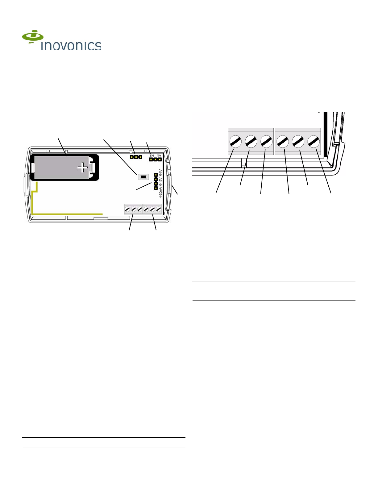
4-20 mA
4-20 mA
0-10V
0-5V
0-10V
0-5V
GND
GND
First Sensor Second Sensor
Installation Instructions - 05373C
1 Overview
The EN1702 transmits analog data from one or two external sensors.
1.1 Inovonics Wireless Contact Information
If you have any problems with this procedure, contact Inovonics Wireless
technical services:
• E-mail: support@inovonics.com
• Phone: (800) 782-2709; (303) 939-9336
1.2 EN1702 Components
• Place the jumper on the bottom two pins, marked 4-20mA, to select a
sensor output of 4-20mA.
• Place the jumper on the middle, marked 0-10V, two pins, to select a
sensor range of 0-10V.
• Place the jumper on the top two pins, marked 0-5V, to select a sensor
range of 0-5V.
2. Referring to Figure 2, use a small screwdriver to attach the external
sensor(s) wiring leads to the appropriate terminal blocks.
3. If the battery has been installed, press the Reset button to complete the
procedure.
Figure 2 EN1702 External Sensor Wiring
Figure 1 EN1702 Components
A First external sensor
terminal block
D Frequency band
selection pins
G Programming
header
B Second external sensor
terminal block
E Reset button F Battery
H Housing release tab
C Sensor output
selection pins
2 Installation and Startup
2.1 Install/Replace the Battery
1. Pry the top lip of the mounting bracket up, and lift the bracket off of the
transmitter.
2. Use your thumb to depress the housing release tab; separate the
housing.
3. If replacing a battery , use the hole in the back of the housing to push the
old battery out of the battery holder.
4. Install the new battery.
5. Press the Reset button to initialize the transmitter. If replacing a battery ,
the transmitter’s most recent programming will be restored upon
initialization.
2.2 Select the Frequency Band
EchoStream products are able to use a range of radio frequencies, and
must be configured for your geographic area. To configure the transmitter:
1. Place a selection jumper on the appropriate frequency band selection
pins.
• Place the jumper on the left two pins, marked AU, to set the frequency
range to 915-928 MHz for Australia.
• Place the jumper on the right two pins, marked NZ, to set the
frequency range to 921-928 MHz for New Zealand.
• Leave the jumper off the pins to set the frequency range to 902-928
MHz for North America.
2. Press the Reset button to complete configuration.
2.3 Attach the Analog Sensors and Select Output
To use the EN1702, you must connect the analog sensor(s) to one or both
of the terminal blocks. To connect the analog sensors:
Note: The analog sensor cable length must not exceed three feet.
1. Place a selection jumper on the appropriate sensor output selection
pins (Fig. 1C).
© Inovonics, 2011 - www.inovonics.com
3 Program the Transmitter
EN1702 transmitters are programmed at the factory. It is not usually
necessary to reprogram EN1702 series transmitters. If you want to
reprogram the transmitter, parameters can be changed using the
programming header.
4 Mount the Transmitter
1. Attach the mounting bracket to the wall, using the included hardware.
Note: There are two mounting holes for standard installation. An optional
third mounting hole is located under the battery. Use the third mounting
hole to secure the housing to the bracket.
2. Hook the bottom of the transmitter into the bracket’s bottom catch, and
press the transmitter into the bracket so that the bracket’s top lip snaps
into place.
5 Television and Radio Interference
This equipment has been tested and found to comply with the limits for a
Class B digital device, pursuant to Part 15 of the FCC Rules. These limits
are designed to provide reasonable protection against harmful interference
in a residential installation. This equipment generates, uses and can
radiate radio frequency energy and, if not installed and used in accordance
with the instructions, may cause harmful interference to radio
communications. However, there is no guarantee that interference will not
occur in a particular installation. If this equipment does cause harmful
interference to radio or television reception, which can be determined by
turning the equipment off and on, the user is encouraged to try to correct
the interference by one or more of the following measures:
• Reorient or relocate the receiving antenna.
• Increase the separation between the equipment and receiver.
• Connect the equipment into an outlet on a circuit different from that to
which the receiver is connected.
• Consult the dealer or an experienced radio/TV technician for help.
6 FCC Part 15 Compliance
This device complies with part 15 of the FCC Rules. Operation is subject to
the following two conditions:
1. This device may not cause harmful interference, and
2. this device must accept any interference received, including
interference that may cause undesired operation.

7 Warranty/Disclaimer
Caution: Changes or modifications not expressly approved by the party
responsible for compliance could void the user's authority to operate the
equipment.
Inovonics Wireless Corporation ("Inovonics") warrants its EchoStream
products ("Product" or "Products") to conform to its own specifications and
to be free of defects in materials and workmanship under normal use for a
period of thirty-six (36) months from the date of manufacture. Within the
warranty period, Inovonics will repair or replace, at its option, all or any part
of the warranted Product. Inovonics will not be responsible for dismantling
and/or reinstallation charges. To exercise the warranty, the User ("User",
"Installer" or "Consumer") must work directly through their authorized
distributor who will be given a Return Material Authorization ("RMA")
number by Inovonics. Details of shipment will be arranged directly through
the authorized distributor.
This warranty is void in cases of improper installation, misuse, failure to
follow installation and operating instructions, alteration, accident or
tampering, and repair by anyone other than Inovonics.
This warranty is exclusive and expressly in lieu of all other warranties,
obligations or liabilities, whether written, oral, express, or implied. There is
no warranty by Inovonics that Inovonics product will be merchantable or fit
for any particular purpose, nor is there any other warranty, expressed or
implied, except as such is expressly set forth herein. In no event shall
Inovonics be liable for an incidental, consequential, indirect, special, or
exemplary damages, including but not limited to loss of profit, revenue, or
contract, loss of use, cost of down time, or interruption of business, nor any
claim made by distributor's customers or any other person or entity.
This warranty will not be modified or extended. Inovonics does not
authorize any person to act on its behalf to modify or extend this warranty.
This warranty will apply only to Inovonics Products. Inovonics will not be
liable for any direct, incidental, or consequential damage or loss
whatsoever, caused by the malfunction of Product due to products,
accessories, or attachments of other manufacturers, including batteries,
used in conjunction with Inovonics Products.
© Inovonics, 2011 - www.inovonics.com 2
 Loading...