

EN1260 EchoStream® Passive Infrared Motion
Detector
Installation and Operation Manual - 05379D
Caution: When pressing the Reset button, make sure you don’t also touch the
frequency band selection pins. Touching the frequency band selection pins whil e
pressing the Reset button can inadvertently set the EN1260 to the wrong frequency
band.
1 Overview
The EN1260 is a low-current motion detector highly sensitive to moving heat (infrar ed
radiation) sources. It features increased immunity to radio frequency interference,
vibration, static, lightning, ambient temperature changes, and other common causes
of false alarms.
The EN1260 includes a range of features, including a wall tamper capability for
increased security, and a fixed or variable sleep time option for normal or high-traffic
applications.
Caution: The EN1260 needs one minute for stabilization afte r power up. During the
stabilization period, the LED will blink twice per second, and the EN1260 will not be
operational.
1.1 Inovonics Wireless Contact Information
If you have any problems with this procedure, contact Inovonics Wireless technical
services:
• E-mail: support@inovonics.com
• Phone: (800) 782-2709; (303) 939-9336
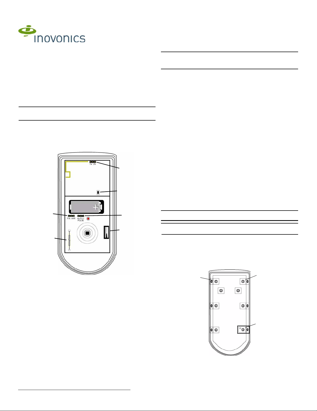
EN1260 Components
A
B
F
C
2.3 Select PIR Sensitivity
The pulse count jumper setting provides control for normal or difficult operating
environments. Automatic pulse count is recommended for reliable operation in
environments subject to temperature fluctuations that may cause false alarms. The
single pulse count mode is more sensitive to minor temperatur e variations, and shou ld
be used in sites where variant heat sources will not cause false alarms. Automatic
pulse count is the factory default because it allows more reliable operation in
environments subject to temperature fluctation. To select PIR sensitivity:
1. Place a selection jumper on the appropriate pulse count selection pins.
• Place the jumper on the left two pins to select automatic pulse count.
• Place the jumper on the right two pins to select single pulse count.
2. Press the Reset button to complete configuration.
2.4 Select Fixed/Variable Sleep Time
The sleep time jumper setting provides control for normal or high-traffic operating
environments. When set to fixed, if the EN1260 senses motion, it will transmit an
alarm, then enter sleep mode for 180 seconds; if motion is sensed when the sleep
time has expired, the EN1260 will transmit another alarm. Fixed sleep time is
recommended for normal operating environments. When set to variable, if the
EN1260 senses motion, it will transmit an alarm, then enter sleep mode for 180
seconds; if motion is sensed before the sleep time has expired, the EN1260 will restart
the 180 second interval. Variable sleep time is recommended for high-traf fic oper ating
environments.
1. Place a selection jumper on the appropriate sleep time selection pins.
• Place the jumper on the left two pins to select fixed sleep time.
• Place the jumper on the right two pins to select variable sleep time.
2. Install the battery.
3. Press the Reset button.
2.5 Register the Transmitter
The EN1260 must be registered with the system receiver in order to be monitored and
supervised. Each EN1260 has a unique factory-programmed identification number.
Refer to the receiver, network coordinator or control panel installation instructions for
details on registering a transmitter.
1. When prompted reset the EN1260, press the EN1260 Reset button.
2. Replace the EN1260 cover.
Caution: The EN1260 should be tested after registration to ensure operation. To test
the EN1260, activate each of the conditions and ensure an appropriate response.
D
E
Figure 1 EN1260 components
A Frequency band
selection pins
D Tamper switch E Test mode reed switch F Sleep time selection
B Reset button C Pulse count selection
pins
pins
2 Installation and Startup
2.1 Install/Replace Battery
To install the battery:
1. Use a small Phillips screwdriver to remove the screw at the bottom of the EN1260
housing; separate the housing.
2. Install/replace the battery.
3. Press the Reset button to initialize the transmitter.
2.2 Select Frequency Band
EchoStream products are able to use a range of radio frequencies, and must be
configured for your geographic area. To configure the EN1260:
1. Place a selection jumper on the appropriate frequency band selection pins (Fig.
1).
• Place the jumper on the left two pins to select 915-928 MHz for Australia.
• Place the jumper on the right two pins to select 921-928 MHz for New Zealand.
• Leave the jumper off the pins to select 902-928 MHz for North America.
2. Press the Reset button.
Note: The EN1260 retains programming data in non-volatile memory. It does not
require re-programming after loss of power.
2.6 Mount the Transmitter
Mount the transmitter.
1. Remove the EN1260 printed circuit board from the housing.
2. Use the included hardware to mount the EN1260 housing back plate to the
mounting surface.
a. If using the wall tamper function for increased security, mount the housing back
plate per Figure 2, ensuring the tamper switch is depressed..
Mount either
corner or wall with
screw only
Figure 2 EN1260 mounting back plate
b. If not using the wall tamper, mount the housing back plate using all appropriate
hardware.
Mount either
corner or wall with
screw only
Mount either corner
or wall with screw
and wall anchor
© Inovonics, 2011 - www.inovonics.com
3 Test the EN1260
3.1 Perform a Walk Test
The walk test is performed to test the PIR, ensuring motion is sensed. To perform a
walk test:
1. Hold the magnet to the reed switch for less than one quarter of a second, The
LED will light three times to indicate the three-minute walk test has been
activated.
Note: To activate the walk test, the magnet shouldn’t remain near the reed switch for
more than one-quarter of a second.
2. Walk in front of the PIR to test the sensor. The LED will light every time the PIR
senses motion.
3. The unit will not transmit alarm signals during the three minute test period. When
the walk test ends, the LED will light six times.
3.2 Perform Transmission Test
1. Hold the magnet to the reed switch for more than four seconds. The LED will light
three times to indicate the transmission test has been acti vated.
2. The unit will transmit alarm and restoral cycles at regular intervals for
approximately one minute. The LED will light every time the unit transmits. Ensure
transmissions are received by your network coordinator, receiver or control panel.
4 Operation
The EN1260 transmitter signals an alarm condition when motion is detected by the
sensor.
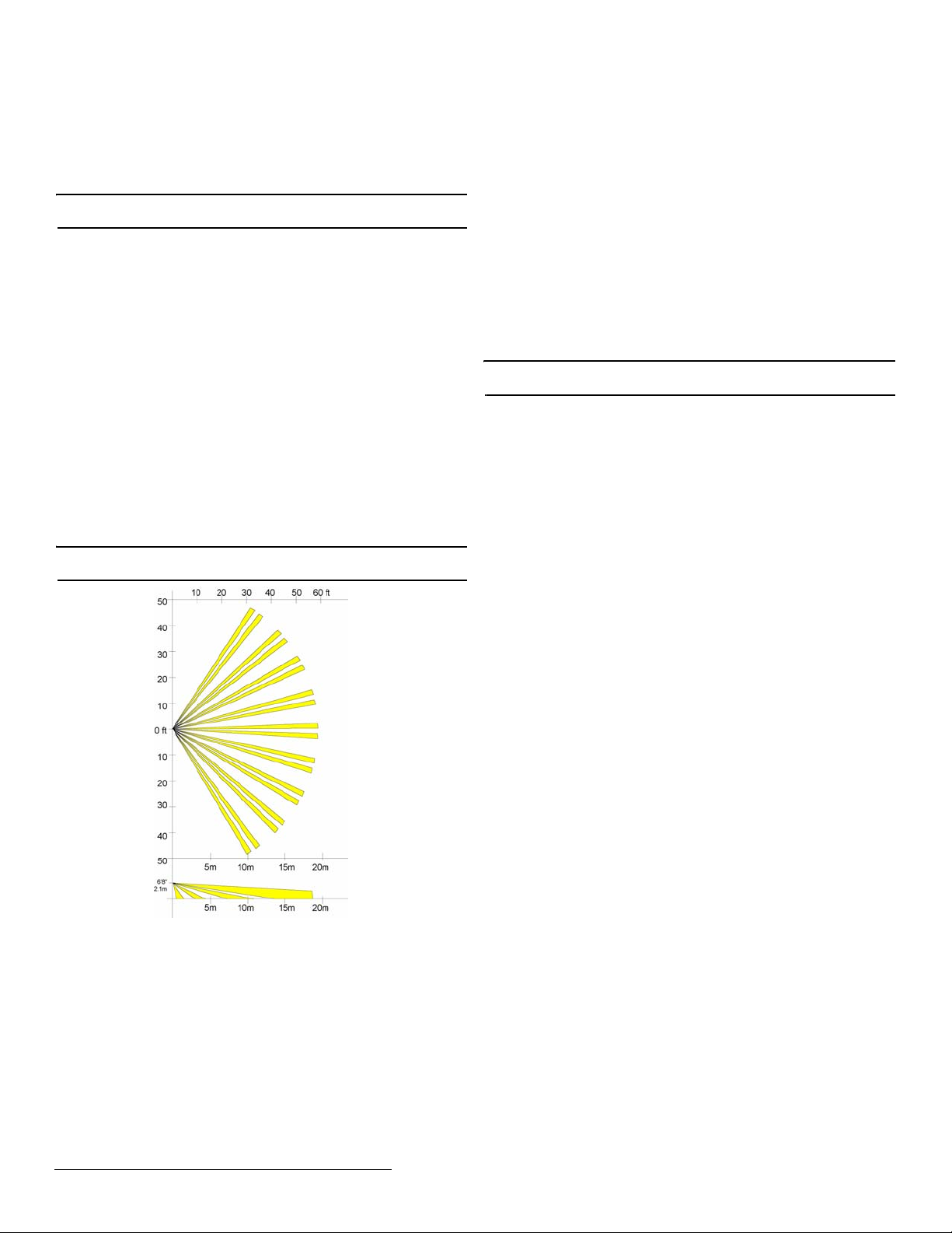
4.1 Zone Pattern for Standard Lens
The standard wide-angle lens has a coverage pattern of 105°, and covers an area 18
m x 18 m (60 ft x 60 ft). It has a total of 52 zones: (18 long range + 16 intermediate +
ten short range + six nearest range + two creep zones). Optional lenses are available.
Contact Inovonics Wireless technical services.
4.2 Lens Options
The following optional lenses are available for the EN1260:
• ACC672CT curtain lens
• ACC672LR long range lens
• ACC672PA pet alley lens
Note: Mounting height of the EN1260 with standard lens may be anywhere within a
range of 7 to 9 feet (2.1 to 2.7 m).
interference will not occur in a particular installation. If this equipment does ca use
harmful interference to radio or television reception, which can be determined by
turning the equipment off and on, the user is encouraged to try to correct the
interference by one or more of the following measures:
• Reorient or relocate the receiving antenna.
• Increase the separation between the equipment and receiver.
• Connect the equipment into an outlet on a circuit different fro m that t o which the
receiver is connected.
• Consult the dealer or an experienced radio/TV technician for help.
7 FCC Part 15 and Industry Canada Compliance
This device complies with part 15 of the FCC Rules and Industry Canada licenseexempt RSS standard(s). Operation is subject to the following two conditions: (1) this
device may not cause interference, and (2) this device must accept any interference,
including interference that may cause undesired operation of the device.
Le présent appareil est conforme aux CNR d'Industrie Canada applicables aux
appareils radio exempts de lice n ce. L'exploitation est autor i s é e a ux deux conditions
suivantes : (1) l'appareil ne doit pas produire de brouillage, et (2) l'utilisateur de
l'appareil doit accepter tout brouillage radioélectrique subi, même si le brouillage est
susceptible d'en compromettre le fonctionnement.
8 Warranty and Disclaimer
Note: Changes or modifications not expressly approved by the party responsible for
compliance could void the user's authority to operate the equipment.
Inovonics Wireless Corporation ("Inovonics") warrants its EchoStream products
("Product" or "Products") to conform to its own specifications and to be free of defects
in materials and workmanship under normal use for a period of thirty-six (36) months
from the date of manufacture. Within the warranty period, Inovonics will repair or
replace, at its option, all or any part of the warranted Product. Inovonics will not be
responsible for dismantling and/or reinstallation charges. To exercise the warrant y, the
User ("User", "Installer" or "Consumer") must work directly through their authorized
distributor who will be given a Return Material Authorization ("RMA") number by
Inovonics. Details of shipment will be arranged directly through the authorized
distributor.
This warranty is void in cases of improper installation, misuse, failure to follow
installation and operating instructions, alteration, accident or tampering, and repair by
anyone other than Inovonics.
This warranty is exclusive and expressly in lieu of all other warranties, obligations or
liabilities, whether written, oral, express, or implied. There is no warranty by Inovonics
that Inovonics product will be merchantable or fit for any particular purpose, nor is
there any other warranty, expressed or implied, except as such is expressly set forth
herein. In no event shall Inovonics be liable for an incidental, consequential, indirect,
special, or exemplary damages, including but not limited to loss of profit, revenue, or
contract, loss of use, cost of down time, or interruption of business, nor any claim
made by distributor's customers or any other person or entity.
This warranty will not be modified or extended. Inovonics does not authorize any
person to act on its behalf to modify or extend this warranty.
This warranty will apply only to Inovonics Products. Inovonics will not be liable for any
direct, incidental, or consequential damage or loss whatsoever, caused by the
malfunction of Product due to products, accessories, or attachments of other
manufacturers, including batteries, used in conjunction with Inovonics Products.
Top
View
Side
View
Figure 3 EN1260 zone map
5 Specifications
Dimensions: 4.5”H x 2.5”Wx 1.6”D (11.4 8cm x 6.4 cm x 4.1 cm)
Operating temperature: -4° to 140°F (-20° to 60°C)
Humidity: 0 - 90% (non-condensing)
Battery: 3V lithium (CR123A orDL123A)
Tamper: Housing and wall tamper
PIR RF interference immunity: Greater than 30 v/m 26 MHz - 1 GHz
Alarm lockout time: 3 minutes
Mounting height: 7 to 9 feet (2.1 to 2.7 m)
6 Television and Radio Interference
This equipment has been tested and found to comply with the limits for a Class B
digital device, pursuant to Part 15 of the FCC Rules. These limits are designed to
provide reasonable protection against harmful interference in a residential inst allation.
This equipment generates, uses and can radiate radio frequency energy and, if not
installed and used in accordance with the instruction s, may cause harmful
interference to radio communications. However, there is no guarantee that
© Inovonics, 2011 - www.inovonics.com 2
 Loading...