

EN1240 EchoStream® Activity Sensor
C
A
D
B
E
G
F
H
I
K
J
Housing
screw
Installation Instructions - 05638A
1 Overview
The EN1240 activity sensor is designed specifically for residential and senior living environments
where a notification of a daily activity is necessar y. The EN1240 leverages the latest motion detector
technology, includ ing whit e ligh t and pet immuni ty, to ensure performance accuracy. Selectable fixed
sleep intervals of two, four, or six hours are used to minimize wireless traffic in large installations,
while confirming daily resident activity. Check-in messages are sent every 30 minutes to provide
effective notification of recent resident activity even when the device is in the fixed sleep cycle.
Caution: The EN1240 needs one minute for stabilization after power up. During the stabilization
period, the LED will blink twice per second, and the EN1240 will not be operational.
Caution: Prior to operation, the EN1240 must be acclimated to the temperature of the install
environment for a period of 60 minutes.
Caution: The EN1240 activity sensor is not designed for use as a security system motion detector.
1.1 Inovonics Wireless Contact Information
If you have any problems with this procedure, contact Inovonics Wireless technical services:
• E-mail: support@inovonics.com
• Phone: (800) 782-2709; (303) 939- 9336
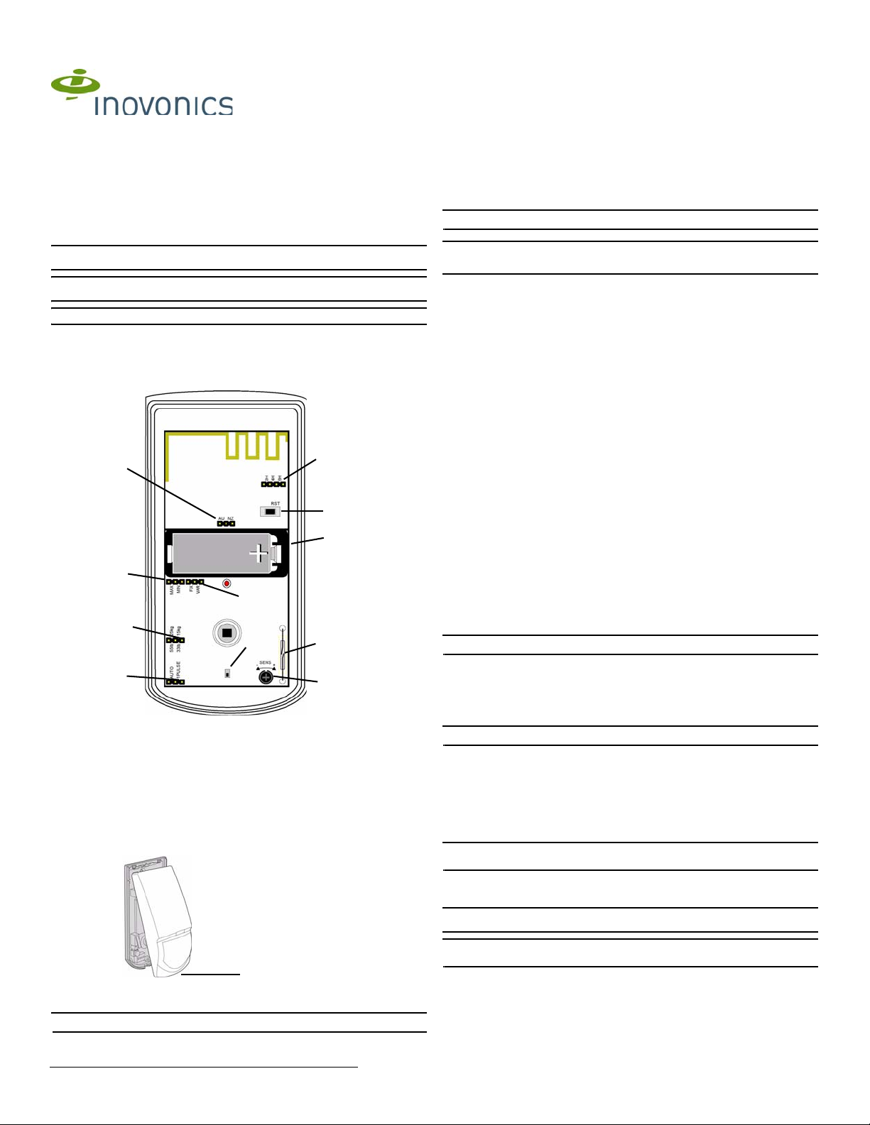
1.2 EN1240 Components
Figure 1 EN1240 components
A Frequency band selection pins B Reset button C Pulse count selection pins
D Pet immunity selection pins E Test mode reed switch F Sleep duration selection pins
G Sensitivity adjustment dial H Battery I Case tamper switch
J Sleep duration selection pins K Sleep time selection pins
2 Installation and Startup
2.1 Install/Replace Battery
To install the battery:
1. Release the housing screw and gently raise the cover.
Figure 2 Open the cover
2. Install the battery in the holder.
3. Press the Reset button to initialize the transmitter.
Note: You must press the Reset button each time the battery is changed.
2.2 Select the Frequency Band
EchoStream products are able to use a range of radio frequencies, and must be configured for your
geographic area. To configure the transmitter:
1. Place a selection jumper on the appropria te frequency band selection pins.
• Place the jumper on the left two pins, marked AU, to set the frequency ra nge to 915-928 MHz
for Australia.
• Place the jumper on the right two pins, marked NZ, to set the frequency range to 921-928
MHz for New Zealand.
• Leave the jumper off the pins to set the frequency range to 902-928 MHz for North America.
Note: Selection jumpers are included in the hardware bag.
2. Press the Reset button to initialize the transmitter.
Caution: When pressing the Reset button, make sure you don’t also touch the frequency band
selection pins. Touching the frequency band selection pi ns while pressing the Reset button can
inadvertently set the wrong frequency band.
2.3 Select Automatic/Pulse Count
The pulse count jumper setting provides control for normal or difficult operating environments.
Automatic pulse count is recommended for reliable operati on in environmen ts subject t o temperature
fluctuations that may cause false alarms. The single pulse count mode is more sensitive to minor
temperature variations, and should be used in sites where variant heat sources will not cause false
alarms.
1. Place a selection jumper on the appropriate pulse count selection pins.
• Place the jumper on the left two pins, marked AUTO, to select automatic pulse count.
• Place the jumper on the right two pins, marked 1 PULSE, to select single pulse count.
2.4 Select Fixed/Variable Sleep Time
The EN1240 activity sensor is shipped from the factory set for a fixed sleep time. The fixed/variable
sleep time setting should not be changed without specific instruction from Inovonics technical
services.
2.5 Select Sleep Duration
The EN1240 activity sensor is shipped from the facto ry set fo r a minimum sleep duration. The sleep
duration setting should not be change d with out spe cific instructio n from Ino vonics technical se rvices.
2.6 Select Fixed Sleep Time
Alarm and Check-In Messages
The EN1240 sends two types of message: alarm and check-in. Alarm messages are sent when the
EN1240 first detects motion. Immediately upon sending an alarm message, the EN1240 enters the
selected sleep cycle, during which no more alarm messages are sent. Check-in messages are sent
by the EN1240 every 30 minutes, even during the sleep cycle, to ensure the EN1240 is still
functional. Check-in messages also include the alarm status as part of the check-in information.
Using Sleep Cycles
Typically, activity monitoring in senior living environments is performed using a daily time window to
confirm resident activity. The EN1240 sleep interval can be set to two, four, or six hours. If you
require multiple alarms during your daily time window you should select a sleep time shorter than
your daily time window.
Setting Sleep Cycle Duration
T o set sleep cycle duration:
1. Place a selection jumper on the appropriate sleep cycle duration selection pins.
• Place the jumper on the left two pins, marked 2H, to set the sleep cycle duratio n to two hours.
• Place the jumper on the middle two pins, marked 4H, to set the sleep cycle duration to four
hours.
• Place the jumper on the right two pins, marked 6H, to set the sleep cycle duration to six
hours.
Note: Selection jumpers are included in the hardware bag.
2.7 Select Pet Immunity
Pet immunity allows the EN1240 to ignore the movement of small animals.
1. Place a selection jumper on the appropriate pet immunity selection pins.
• Place the jumper on the left two pins, marked 55lb/25kg to select pe t immuni ty for anima ls up
to 55 pounds (25 kilograms) in weight.
• Place the jumper on the right two pins, marked 33lb/15kg to select pet immunity for animals
up to 33 pounds (15 kilograms).
Note: If neither option is selected, the EN1240 will default to the 55lb/25kg selection.
2.8 Adjust sensitivity
The sensitivity of the activity sensor can be adjusted to fit your specific application. To adjust
sensitivity:
1. Use a philip’s head screwdriver to turn the sensitivity adjustment dial.
• Turn the dial to the left, towards the minus sign, to decrease the activity sensor’s sensitivity.
• Turn the dial to the right, towards the plus sign, to increase the activity sensor’s sensitivity.
2.9 Register the Transmitter
The EN1240 must be registered with the system receiver in order to be monitored and supervised.
Each EN1240 has a unique fact ory-programmed identificati on number.
Note: The transmitter’s unique identification number is the eight digit serial number found on the
serial number label.
Refer to the receiver installation instructions for details on registering a transmitter.
1. When prompted, press the Reset button.
2. Replace the EN1240 cover.
3. Replace the housing screw.
Caution: The EN1240 should be tested after registration to ensure operation. To test the EN1240,
activate each of the conditions and ensure an appropriate response.
Note: The EN1240 retains programming data in non-volatile memory. It does not require reprogramming after loss of power.
2.10 Mount the Transmitter
Mount the transmitter.
1. Remove the EN1240 printed circuit board from the housing.
2. Use the included hardware to mount the EN1240 housing back plate to the mounting surface.
© Inovonics, 2009 - www.inovonics.com, 8/17/10, P/N 7102855 Rev. A
a. If using the wall tamper function for increased security, mount the housing back plate per
Mount either
corner or wall with
screw only
Mount either
corner or wall
with screw and
wall anchor
Mount either corner
or wall with screw
only
Ceiling mount
installation
Wall mount
installation
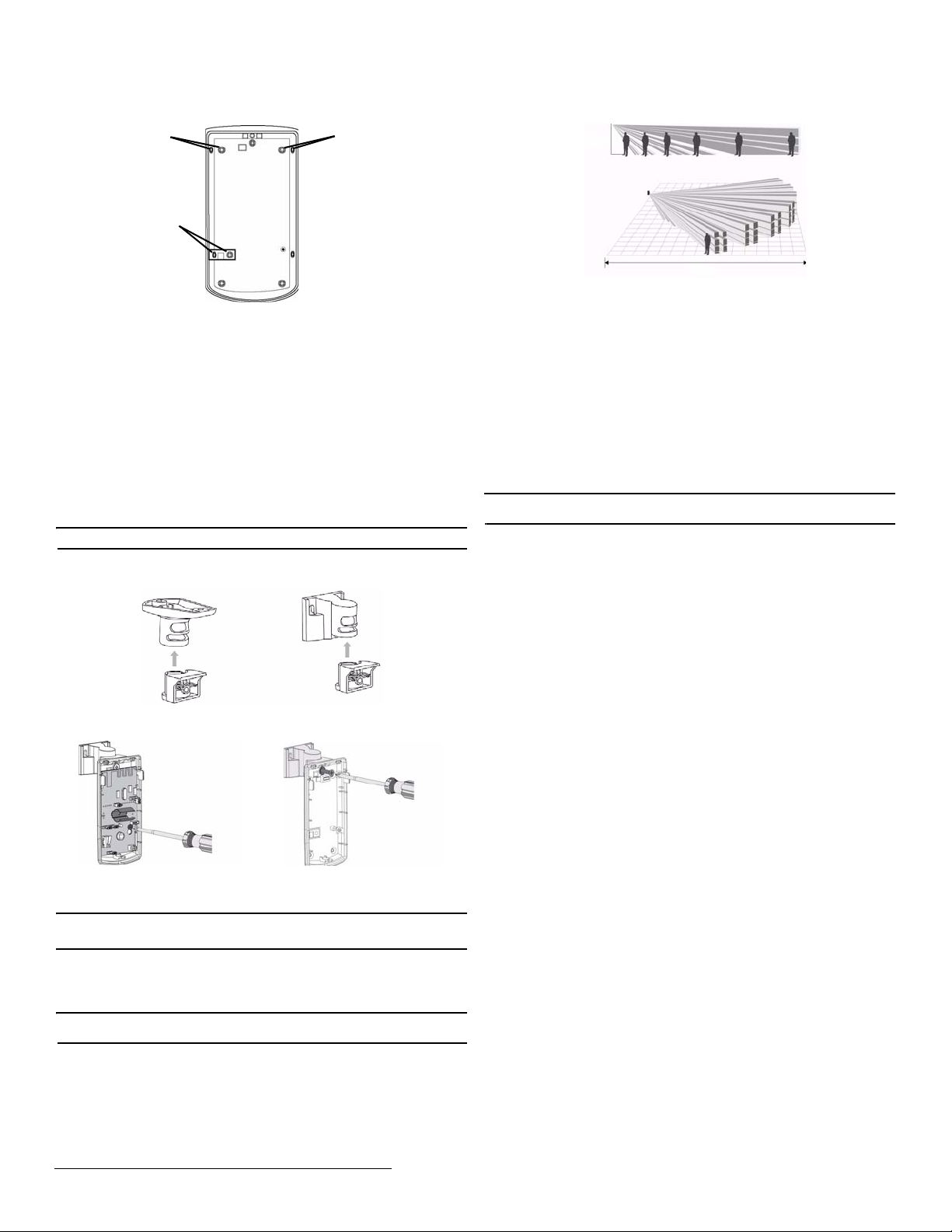
6’ 10”- 8’ 10”
49’
Figure 3, ensuring the tamper switch is depressed.
4 Operation
The EN1240 transmitter signals an alarm condition when motion is detected by the sensor.
Figure 3 EN1240 mounting back plate
b. If not using the wall tamper, mount the housing back plate using all appropriate hardware.
2.1 Mounting Considerations
The following should be considered when mounting the EN1240:
• The activity sensor should be mounted such that the expected intrusion motion is
perpendicular to the protection zones
• The activity sensor may not detect motion behind obstru ction s, includ ing bl inds, cu rt ains, an d
drapes
• The activity sensor should be mounted on a solid, vibration-free mounting surface
• Fans and blowers can cause false alarms.
• The following may cause false alarms:
- Fans
- Blowers
- Drafts
- Windows
- Heat and cooling sources
- Sunlight
- Animals
2.2 Optional Ceiling/Wall Mount Application
The optional ceiling and wall mount brackets are available separately from Inov onics, part number
ACC665.
Note: Applications that require the back tamper cannot use the ceiling or wall mount bracket.
Figure 4 Ceiling and wall mount brackets
To mount a ceiling or wall bracket:
1. Remove the pcb board.
2. Attach the housing to the bracket.
Figure 6 Standard mounting height and range
5 Specifications
Dimensions: 4.5”H x 2.5”Wx 1.6”D (11.4 cm x 6.4 cm x 4.1 cm)
Detection method: Quad element PIR
Storage temperature: -4° to 140°F (-20° to 60°C)
Operating temperature: 32° to 122°F (0° to 50°C), 90% relative humidity, non-condensing
Humidity: 0 - 90% (non-condensing)
Battery: 3V LiMnO2, BAT604 (Panasonic CR123A or Duracell DL123A)
Power requirement: 3VDC, 60 mA
Temperature compensation: Yes
Tamper: Housing and wall tamper
PIR RF interference immunit y: Greater than 30 v/m 26 MHz - 1 GHz
Stabilization period: one minute
Alarm lockout time: two, four, or six hours
Walk test period: five minutes
Mounting height: 6’ 10” to 8’ 10” (2.1 to 2.7m)
6 Warranty/Disclaimer
Note: Changes or modifications to this unit not expressly approved by Inovonics may void the
installer's authority to operate the equipment as well as the product warranty.
Inovonics Wireless Corporation ("Inovonics") warrants its EchoStream products ("Product" or
"Products") to conform to its own specifications and to be free of defects in materials and
workmanship under normal use for a period of thirty-six (36) months from the date of manufacture.
Within the warranty period, Inovonics will repair or replace, at its option, all or any part of the
warranted Product. Inovonics will not be responsible for dismantling and/or reinstallation charges. To
exercise the warranty, the User ("User", "Installer" or "Consumer") must work directly through their
authorized distributor who will be given a Return Material Authorization ("RMA") number by
Inovonics. Details of shipment will be arranged directly through the authorized distributor.
This warranty is void in cases of improper installation, misuse, failure to follow installation and
operating instructions, alteration, accident or tampering, and repair by anyone other than Inovonics.
This warranty is exclusive and expressly in lieu of all other warranties, obligations or liabilities,
whether written, oral, express, or implied. There is no warranty by Inovonics that Inovonics product
will be merchantable or fit for any particular purpose, nor is there any other warranty, expressed or
implied, except as such is expressly set forth herein. In no event shall Inovonics be liable for an
incidental, consequential, indirect, special, or exemplary damages, including but not limited to loss of
profit, revenue, or contract, loss of use, cost of down time, or interruption of business, nor any claim
made by distributor's customers or any other person or entity.
This warranty will not be modified or ext ended . Inov onics does n ot autho rize an y per son to act on it s
behalf to modify or extend this warranty.
This warranty will apply only to Inovonics Products. Inovonics will not be liable for any direct,
incidental, or consequential damage or loss whatsoever, caused by the malfunction of Product due
to products, accessories, or attachments of other manufacturers, including batteries, used in
conjunction with Inovonics Products.
Figure 5 Remove the pcb board and attach the housing to the bracket
3. Replace the pcb board.
3 Test the EN1240
Caution: The EN1240 should be tested after registration, and at least once a year thereafter, to
ensure operation. To test the EN1240, activate each of the conditions and ensure an appropriate
response.
3.1 Perform a Walk Test
The walk test is performed to ensure mo tion is sense d and a n RF tran smis sio n resul ts. To perform a
walk test:
1. Swipe a magnet past the reed switch. The five minute walk test will begin; every time motion is
sensed, the LED will light.
Note: During walk test, the EN1240 will not transmit alarms when motion is detected; only the LED
will light.
2. Walk in front of the activity sensor to test the sensor.
3. After five minutes the walk test will automatically end.
© Inovonics, 2009 - www.inovonics.com, 8/17/10, P/N 7102855 Rev. A 2
 Loading...