

Page 1
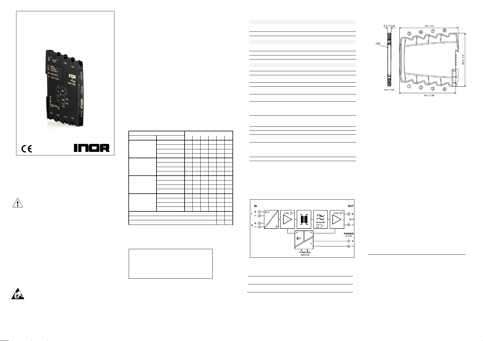
S1 -
Input
Output 1 2 3 4 5 6
0 … 20 mA
4 … 20 mA
● 0 … 10 V
● ● 2 … 10 V
● ● ●
0 … 20 mA
● 4 … 20 mA
0 … 10 V
● ● ● 2 … 10 V
● ●
0 … 20 mA
4 … 20 mA
●
0 … 10 V
●
●
2 … 10 V
●
● ●
0 … 20 mA
●
4 … 20 mA
0 … 10 V
● ●
●
2 … 10 V
●
●
Filter 5kHz
Filter 100 Hz
●
Filter 10 Hz
●
Input
Voltage
Current
Input signal
(calibrated switchable)
0 … 10 V
2 … 10 V
0 … 20 mA
4 … 20 mA
Input resistance
≥ 100 kΩ
≤ 25 Ω
Overload
≤ 30 V
≤ 50 mA
Output
Voltage
Current
Output signal
(calibrated switchable)
0 … 10 V
2 … 10 V
0 … 20 mA
4 … 20 mA
Load
≤ 5 mA (2 kΩ at 10 V)
≤ 12 V (600 Ω at 20 mA)
Linear trans miss ion ran ge
-1 to +110 %
Ripple
< 10 mV
rms
General data
Transmission error
< 0.1 % full scale
Temperature coefficient1)
< 100 ppm/K
(switchable)
Response time T99
150 µs, 7 ms, 70 ms
Test voltage
3 kV, 50 Hz, 1 min.
Input against output against power supply
Working voltage2)
(Basic insulation)
600 V AC/DC for overvoltage category II and
contamination class 2 acc. to EN 61010-1
Protection against
Protective Separation by reinfor ced insulation ac c. to
1 up to 300 V AC/DC for overvoltage
and output and power supply.
Ambient temperature
Operation
and storage
-25 °C to +70 °C (-13 to +158 °F)
Power supply
24 V DC
16.8 V … 31.2 V, approx. 0.7 W
EMC3)
EN 61326-1
Construction
6.2 mm (0.244’’) housing, protection type: IP 20
mounting on 35 mm DIN rail acc. to EN 60715
Connection
Solid: 0.5 mm2 - 4 mm2 / AWG 20-12
Screw terminal torque 0.8 Nm / 7 lbf in
Weight
Approx. 70 g
Product
Input / Output
Order No.
IsoPAQ-641
In-Rail-Bus for power supply
calibrated
switchable
70ISL64100
Terminal assignments
1
Input I +
5
Output +
2
Input I −
6
Output −
3
Input U +
7
Power supply +
4
Input U −
8
Power supply −
LIMITED WARRANTY
warrants that the Product will be free from defects in
the date of delivery (”Limited Warranty”). This Limited
as to suitability for any particular purpose, performance,
course of dealing, including implied warranties of
Internet: www.inor.com
USER INSTRUCTIONS English
Standard Signal Converter
IsoPAQ-641
Read these instructions before using the product and retain for future information.
► Before Startup
When operating the signal converter, certain parts
of the module can carry dangerous voltage!
Ignoring the warnings can lead to serious injury
and/or cause damage!
The signal converter should only be installed and
put into operation by qualified staff. The staff must
have studied the warnings in these operating
instructions thoroughly.
The signal converter may not be put into operation if
the housing is open.
In applications with high operating voltages
sufficient distance and isolation as well as shock
protection must be ensured.
Safe and trouble-free operation of this device can
only be guaranteed if transport, storage and
installation are carried out correctly and operation
an maintenance are carried out with care.
Appropriate safety measures against electrostatic
discharge (ESD) should be taken during range
selection and assembly on the transmitter.
IsoPAQ-641
► Short description
The Standard Signal Converter is used for electrical isolation and
conversion of unipolar process signals. The input and output range
can be set by using DIP switch and due to the calibrated range
selection no further adjustment is necessary.
The 3-way isolation guarantees reliable decoupling of the sensor
circuit from the processing circuit and prevents linked measurement
circuits from influencing each other. The Protective Separation with
high isolation level provides protection for personnel and
downstream devices against impermissibly high voltage.
The auxiliary power can be supplied via the connection terminals or
type-specific via the optional In-Rail-Bus connector (see
accessories). A green LED on the front of the unit has been provided
to monitor the power supply.
► Functioning
The input signal is modulated and then electrically decoupled using
a transformer. The isolated signal is then made available at the
output, demodulated, filtered and amplified.
► Settings
Set the input and output ranges with DIP switch as indicated in the
following table:
0 … 20 mA
4 … 20 mA
0 … 10 V
2 … 10 V
Factory settings: all switches in position OFF ● = on
► Mounting, Electrical Connection
The isolation transmitter is mounted on standard 35 mm DIN rail.
► Technical Data
Cut-off frequency -3 dB
dangerous body
2)
currents
(captive plus-minus
clamp screws)
1) Average TC in specified operating temperature range
2) As far as rel evant the standards and rules ment ioned above are considered
by development and production of our devi ces. In addition r elevant assembly
rules are to be considered by install ation of our devices in other equipm ent.
For applications with high working voltages, take measures to prevent
accidental contact and m ak e sure t hat there is suffici ent distance or insulation
between adjacent situated devices.
3) Minor deviations possible during int erference
► Block Diagram
► Order Information
5 kHz, 100 Hz, 10 Hz
EN 61010category II and contami nation cl ass 2 between i nput
Transport
Fine-stranded: 0.5 mm2 - 2.5 mm2 / AWG 20-14
Stripped length: 6-8 mm / 0.28 in
-40 °C to +85 °C (-40 to +185 °F)
► Dimensions
INOR Process AB, or any other affiliated company within the
Inor Group (hereinafter jointly referred to as ”Inor”), hereby
materials or workmanship for a period of five (5) years from
Warranty is limited to repair or replacement at Inor’s option
and is effective only for the first end-user of the Product. This
Limited Warranty applies only if the Product:
1. is installed according to the instructions furnished by
Inor;
2. is connected to a proper power supply;
3. is not misused or abused; and
4. there is no evidence of tampering, mishandling, neglect,
accidental damage, modification or repair without the
approval of Inor or damage done to the Product by
anyoneother than Inor.
Inor specifically disclaims any express warranty not provided
herein and any implied warranty, guarantee or representation
quality and absence of any hidden defects, and any remedy
for breach of contract, which but for this provision, might
arise by implication, operation of law, custom of trade or
merchantability and fitness for a particular purpose. Except
as provided herein, Inor further disclaims any responsibility
for losses, expenses, inconveniences, special, direct,
secondary or consequential damages arising from ownership
or use of the product.
Customer pays freight to Inor, and Inor will pay the return
freight by post or other “normal” way of transport. If any other
type of return freight is requested, customer pays the whole
return cost.
INOR Process AB
PO Box 9125
200 39 MALMÖ
SWEDEN
Phone: +46 (0)40 312 560
Fax: +46 (0)40 312 570
E-Mail: [email protected]
06-2015 - 1000311498
Page 2
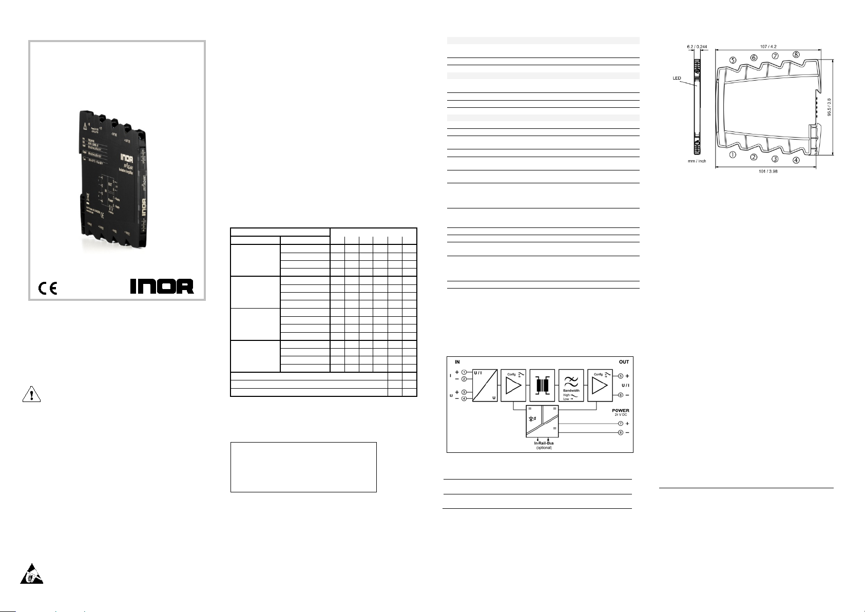
S1 -
Eingang
Ausgang
1 2 3 4 5
6
0 … 20 mA
4 … 20 mA
●
0 … 10 V
● ●
2 … 10 V
● ● ●
0 … 20 mA
● 4 … 20 mA
0 … 10 V
● ● ● 2 … 10 V
● ●
0 … 20 mA
4 … 20 mA
●
0 … 10 V
●
●
2 … 10 V
●
● ●
0 … 20 mA
●
4 … 20 mA
0 … 10 V
● ● ● 2 … 10 V
●
●
Bandbreite 5 kHz
Bandbreite 100 Hz
●
Bandbreite 10 Hz
●
Produkt
Eingang /
Ausgang
Best.-Nr.
IsoPAQ-641
In-Rail-Bus zur Spannungsversorgung
kalibriert
umschaltbar
70ISL64100
Klemmenbelegung
1
Eingang I +
5
Ausgang +
2
Eingang I −
6
Ausgang −
3
Eingang U +
7
Versorgung +
4
Eingang U −
8
Versorgung −
Eingang
Spannung
Strom
Eingangssignal
(kalibriert umschaltbar)
0 … 10 V
2 … 10 V
0 ... 20 mA
4 ... 20 mA
Eingangswiderstand
≥ 100 kΩ
≤ 25 Ω
Überlastbarkeit
≤ 30 V
≤ 50 mA
Ausgang
Spannung
Strom
Ausgangssignal
(kalibriert umschaltbar)
0 … 10 V
2 … 10 V
0 ... 20 mA
4 ... 20 mA
Bürde
≤ 5 mA (2 kΩ bei 10 V)
≤ 12 V (600 Ω bei 20 mA)
Übertragungsbereich
-1 bis +110 %
Restwelligkeit
< 10 mV
eff
Allgemeine Daten
Übertragungsfehler
< 0,1 % vom Endwert
Temperaturkoeffizient1)
< 100 ppm/K
(umschaltbar)
Einstellzeit T99
150 µs, 7 ms, 70 ms
Prüfspannung
3 kV, 50 Hz, 1 Min .
Eingang gegen Ausgang gegen Versorgung
Arbeitsspannungen2)
(Basisisolierung)
600 V AC/DC bei Überspannungskategorie II und
Verschmutzungsgrad 2 nach EN 61010-1
Schutz gegen
Sichere Trennung durch verstär kte Isolierung gemäß
1 bis zu 300 V AC/DC bei
grad 2 zwischen allen Kreisen.
Umgebungstemperatur
Betrieb
Lagerung
-25 °C bis +70 °C (-13 bis +158 °F)
Versorgung
24 V DC
16,8 V … 31,2 V, ca. 0,7 W
EMV3)
EN 61326-1
Bauform
6,2 mm (0.244’’) Anreihgehäuse, Schutzart: IP 20
Montage auf 35 mm Hutschiene nach EN 60715
Anschluss
eindrähtig: 0,5 mm2 - 4 mm2 / AWG 20-12
Anzugsmoment 0,8 Nm / 7 lbf in
Gewicht
ca. 70 g
BESCHRÄNKTE GARANTIE
AB, oder jede andere angegliederte
Zeitraum von fünf (5) Jahren ab Lieferdatum frei von
für den ersten Endbenutzer des Produktes. Diese
Produkt, die durch andere als INOR verursacht wurden.
drücklich jegliche nicht hierin gewährte
vertragliche Gewährleistung, Garantie oder Reklamation
Handelssitte, oder Geschäftsverlauf ergeben könnten,
einschließlich stillschweigender Garantien der
Zweck, außer wie hierin gewährt; INOR lehnt weiterhin
für Verluste, Unkosten,
der Rückfracht verlangt wird, übernimmt der Kunde die
Internet: www.inor.com
BEDIENUNGSANLEITUNG Deutsch
Normsignal-Trennverstärker
IsoPAQ-641
Lesen Sie diese Bedienungsanleitung bev or Si e das Produkt installieren
und heben Sie diese für weitere Informationen auf.
► Vor der Inbetriebnahme
Beim Betrieb des Signalkonverters können
bestimmte Teile des Moduls unter gefährlicher
Spannung stehen! Durch Nichtbeachtung der
Warnhinweise können schwere Körperverletzungen
und/oder Sachschäden entstehen!
Der Signalkonverter sollte nur von qualifiziertem
Fachpersonal installiert und in Betrieb genommen
werden. Das Personal sollte sich mit den Warnhinweisen dieser Betriebsanleitung gründlich
auseinandergesetzt haben.
Der Signalkonverter darf nicht bei geöffnetem
Gehäuse in Betrieb genommen werden.
Bei Anwendu ng en mi t ho he n Arb ei t ss p a nnu nge n i st
auf genügend Abstand bzw. Isolation und auf
Berührungsschutz zu achten.
Der einwandfreie und sichere Betrieb dieses
Gerätes setzt sachgemäßen Transport, fachgerechte
Lagerung, Montage sowie sorgfältige Bedienung
und Instandha lt ung vo raus .
Bei Montage und Einstellarbeiten am
Trennverstärker ist auf Schutzmaßnahmen gegen
elektrostatische Entladung (ESD) zu achten!
IsoPAQ-641
► Kurzbeschreibung
Der Normsignal-Trennverstärker wird zur galvanischen Trennung
und Umsetzung von unipolaren Prozesssignalen eingesetzt. Einund Ausgangssignal sind über DIP-Schalter kalibr iert umschaltbar,
ein Nachjustieren der Messbereiche ist nicht notwendig.
Die 3-Wege-Trennung gewährleistet eine sichere Entkopplung des
Sensorkreises vom Auswertkreis und vermeidet eine gegenseitige
Beeinflussung von untereinander verketteten Messkreisen. Die sichere
Trennung mit hoher Prüfspannung schützt das Wartungspersonal und
nachfolgende Geräte vor unzulässig hoher Spannung.
Die Spannungsversorgung kann wahlweise über die Anschlussklemmen oder typabhängig über den In-Rail-Bus erfolgen (siehe
Zubehör). Zur Überwachung der Versorgung ist an der Gerätefront
eine grüne LED vorgesehen.
► Funktionsweise
Das Eingangssignal wird moduliert und mittels Übertrager galvanisch
entkoppelt. Das potentialgetrennte Signal wird danach demoduliert,
gefiltert und verstärkt am Ausgang zur Verfügung gestellt.
► Einstellungen
Einstellung von Ein- und Ausgangsbereich mittels DIP-Schalter gemäß
folgender Tabelle:
0 … 20 mA
4 … 20 mA
0 … 10 V
2 … 10 V
Werkseinstellung: alle Schalter in Position OFF ● = on
► Montage, elektrischer Anschluss
Der Trennverstärker wird auf TS35 Normschienen aufgerastet.
► Technische Daten
Grenzfrequenz -3 dB
gefährliche
Körperströme
(Unverlierbare Plus-MinusKlemmschrauben)
1) mittlerer TK im spezifizierten Betri ebstemperaturbereich
2) Die angeführten Normen und B estimmungen werden bei der Entwicklung und
3) während der Störeinwirkung sind geringe A bweic hungen m öglich
► Blockschaltbild
► Bestelldaten
2)
Herstellung unserer Produkte b erücksichti gt, soweit sie an wendbar sind. Di e
Errichtungsbestimmungen sind beim Einbau unserer Produkte i n Geräte und
Anlagen zusätzlich zu beachten. Bei Anwendungen mit hohen
Arbeitsspannungen ist auf genügend Abstand bzw. Isolation zu
Nebengeräten und auf Berührungsschutz zu achten.
5 kHz, 100 Hz, 10 Hz
EN 61010Überspannungskategorie II und Verschmutzungs-
Transport und
feindrähtig: 0,5 mm2 - 2,5 mm2 / AWG 20-14
Abisolierlänge: 6-8 mm / 0.28 in
-40 °C bis +85 °C (-40 bis +185 °F)
► Abmessungen
INOR Process
Gesellschaft innerhalb der INOR-Gruppe (nachfolgend INOR
genannt), garantiert hiermit, dass das Produkt über einen
Material- und Verarbeitungsfehlern sein wird (”beschränkte
Garantie“). Diese beschränkte Garantie ist nach Wahl der
INOR beschränkt auf Reparatur oder Austausch und gilt nur
beschränkte Garantie gilt nur, wenn das Produkt:
1. gemäß den von INO R zur Verfügung gestellten Anweisungen
installiert w ir d;
2. an eine ordnungsgemäße Stromversorgung angeschlossen ist;
3. ni cht missbräuchlich oder zweckentfremdet eingesetzt wird;
und
4. wenn es keine Beweise gibt für unzulässige Veränderungen,
falsche Handhabung, Vernachlässigung, Modifikation oder
Reparatur ohne Genehmigung von INOR, oder Schäden am
Diese beschränkte Garantie wird von INOR gewährt und
beinhaltet die einzige gewährte vertragliche Gewährleistung.
Inor lehnt aus
bezüglich der Eignung für einen speziellen Zweck, Leistung,
Qualität und Fehlen von Rechtsmitteln für Vertragsbruch, die
sich ohne diese Bestimmung stillschweigend, kraft Gesetz,
handelsüblichen Qualität und Eignung für einen speziellen
jegliche Verantwortung ab
Unannehmlichkeiten, immaterielle, direkte, sekundäre oder
Folgeschäden, die sich aus dem Besitz oder Gebrauch des
Produktes ergeben.
Der Kunde übernimmt die Frachtkosten für den Transport zu
INOR, und INOR bezahlt die Rückfracht per Post oder mit
anderen ”normalen“ Transportarten. Wenn eine andere Art
gesamten Rücksendekosten.
INOR Process AB
PO Box 9125
200 39 MALMÖ
SWEDEN
Telefon: +46 (0)40 312 560
Fax: +46 (0)40 312 570
E-Mail: [email protected]
06-2015 - 1000311498
 Loading...