


LM-2
Digital Air/Fuel Ratio Meter
User Manual
This manual assumes that firmware version 1.18 or later is installed.
 Warning!
It is extremely important to avoid hot-plugging sensor connections. Do not connect or disconnect the sensor connectors while the unit is powered ON.
The Oxygen Sensor used in this device gets very hot in operation. Do not touch the hot sensor. Do not let a hot sensor touch a combustible surface. Do not use the sensor with or near flammable liquids or gases. Failure to heed these warnings may result in severe burns, explosions or fires.
When installed in the exhaust, the oxygen sensor MUST be connected and operating with the LM-2 whenever the car is running. An unpowered oxygen sensor will be quickly damaged when exposed to hot exhaust gases.
1 |
11-0122B |
TABLE OF CONTENT |
|
|
|||
1 |
LM-2 ......................................................................................................... |
|
|
3 |
|
|
1.1 |
Main Screen ....................................................................................... |
|
5 |
|
|
1.2 |
Status Bar........................................................................................... |
|
5 |
|
|
1.3 |
Configuration Menu Screen ............................................................... |
|
7 |
|
2 |
Air/Fuel Ratio Setup................................................................................. |
|
8 |
||
|
2.1 |
Sensor Placement .............................................................................. |
|
8 |
|
|
2.2 |
Sensor Calibration.............................................................................. |
|
9 |
|
|
2.3 |
Calibration Schedule ........................................................................ |
|
10 |
|
3 |
OBD-II .................................................................................................... |
|
|
11 |
|
|
3.1 |
Selecting OBD-II Channels on the LM-2.......................................... |
|
11 |
|
|
3.2 |
Check Vehicle Trouble Codes on the LM-2 ..................................... |
|
12 |
|
|
3.3 |
Clear Vehicle Trouble Codes on the LM-2....................................... |
|
12 |
|
|
3.4 |
Selecting Channels with the LM Programmer software ................... |
|
12 |
|
|
3.5 |
Check and Clear Vehicle Trouble Codes with LM Programmer ...... |
13 |
||
|
3.6 |
OBD II connection diagnostic trace.................................................. |
|
14 |
|
4 |
Analog Cable.......................................................................................... |
|
14 |
||
|
4.1 |
RPM Input ........................................................................................ |
|
14 |
|
|
4.1.1 |
Enable/Disable RPM ................................................................. |
|
15 |
|
|
4.1.2 |
Configure RPM.......................................................................... |
|
15 |
|
|
4.1.3 Attenuating a Tach Signal ......................................................... |
|
16 |
||
|
4.2 |
Analog Inputs ................................................................................... |
|
17 |
|
|
4.2.1 |
Enable/Disable Analog Inputs ................................................... |
|
17 |
|
|
4.2.2 |
Wiring Analog Inputs ................................................................. |
|
17 |
|
|
4.3 |
Analog Outputs Factory Default Settings......................................... |
|
17 |
|
|
4.3.1 |
Programming Analog Outputs .................................................. |
|
18 |
|
|
4.3.2 |
Advanced output programming ................................................. |
|
19 |
|
|
4.3.3 |
Wiring Analog Outputs .............................................................. |
|
19 |
|
5 |
Data Logging.......................................................................................... |
|
20 |
||
|
5.1 |
Recording ......................................................................................... |
|
21 |
|
|
5.2 |
Log File Format ................................................................................ |
|
22 |
|
|
5.3 |
Downloading Logs from Memory Card............................................. |
|
22 |
|
|
5.4 |
Playback........................................................................................... |
|
22 |
|
6 Software (LogWorks 3 and LM Programmer) ........................................ |
|
23 |
|||
|
6.1 |
Download the Logworks 3 software package .................................. |
|
23 |
|
|
6.2 |
Installing software............................................................................. |
|
23 |
|
|
6.3 |
Driver Instalation .............................................................................. |
|
23 |
|
|
6.4 |
Updating Firmware ........................................................................... |
|
23 |
|
|
6.5 |
Changing Sensor Type .................................................................... |
|
25 |
|
Appendix A: Specifications............................................................................ |
|
26 |
|||
Appendix B: Limited Warranty....................................................................... |
|
27 |
|||
Appendix C: Error Codes and Troubleshooting Tips .................................... |
|
28 |
|||
2 |
|
|
|
11-0122B |
|
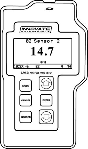
1 LM-2
The LM-2 is a single or dual channel wideband controller with a built-in OBD II scan tool, RPM input, four analog inputs, MTS serial I/O, SD memory card recording and two analog outputs.
Front
MODE
Press once to cycle through channel display screens. Press and HOLD to enter Setup Menu.
CANCEL
Press to cancel out of menu or to stop recording.
RECORD
Press once to record or a second time to stop recording. Press and HOLD to force a new log.
UP
Scroll through available channels. Move through menu
ENTER
Accept an entry in the menu screen.
DOWN
Scroll through available channels. When in the Move through menu
3 |
11-0122B |

Left
Inductive Clamp |
MTS Serial IN |
MTS Serial OUT |
Top |
|
|
|
|
SD Memory Card |
|
|
USB Connector |
Bottom |
|
|
|
|
|
Analog Cable |
|
|
|
Power |
|
|
|
OBD-II |
|
|
|
Connector |
|
|
|
Sensor Port # 2 |
|
|
Sensor Port # 1 |
|
|
|
(Enabled with the |
|
|
|
|
|
|
4 |
|
Dual Channel version) |
11-0122B |
|
|||
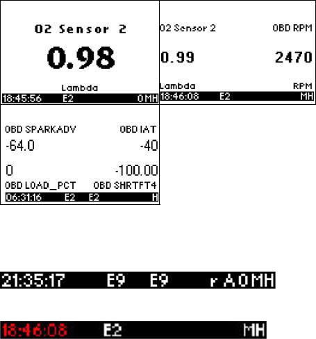
1.1Main Screen
There are 3 different screen view options: one channel, two channels, and four channels. These can be cycled by momentarily pressing the MODE button. The type of channels being displayed can be changed by using the UP and DOWN arrows.
One Channel |
Two Channels |
Four Channels
1.2Status Bar
The bottom edge of the screen is the status bar and will look something like this:
The left most portion is the current time (which can be set via menu and is set automatically by LM Programmer).
5 |
11-0122B |
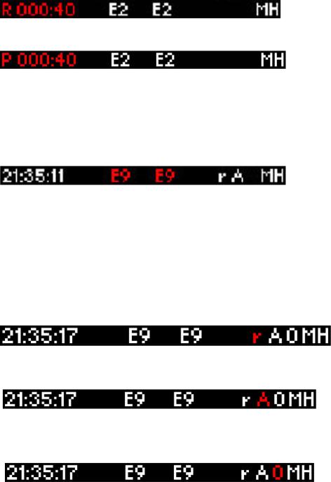
During Recording, an upper case ‘R’ and a counter will display on the lower left:
Counting minutes and seconds of recording.
Similarly, during playback a upper case ‘P’ and a counter will display:
Counting elapsed time during playback.
Note: If Recording does not start (see later section), also look here, the word “Card?” will appear if no SD card is detected when Record is selected. The word “Full!” will appear if you have either filled the SD card, or exhausted the available log names (see section on recording).
Moving to the right, the next two indications are O2 sensor status, which can be one of the following:
HW |
- Heater Warm-up |
Cal |
- Calibrating |
O2 |
- Reading O2 context (lambda over 8.something) |
L |
- Reading Lambda (or AFR) |
Ex |
- Error, Check Appendix E for error code meanings and trouble |
shooting tips
Note: If the LM-2 is a single channel model, the second indication will be blank, not an error code.
The next indicator, “R”, will appear when a) RPM is selected for logging/use (see menus) and b) an RPM signal is detected. Note, when RPM is enabled, but no RPM signal is detected, this symbol will appear in lower case (“r”).
The “A” indicator means that the 4 Analog Inputs are selected for logging/Use (see menus). It is all or nothing. The display will be blank if disabled.
The “O” indicates that an OBD-II connection is active. This indicator will blink at the relative ‘sample rate’, which will vary on the number of channels selected and the vehicle’s protocol. The display will be blank if the unit is not connected to an OBD-II port.
6 |
11-0122B |
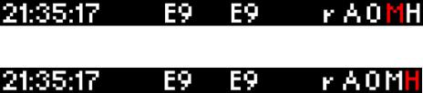
The blinking “M” indicates that MTS serial data is being generated. This will blink at the relative MTS packet rate (for comparison with the O indicator). If the unit is not the “head” unit, then this will only blink when packets are being received via the Serial In connector.
Last, “H” indicates that the unit is the MTS head unit. If the unit is not head this indicator will appear as a “-“
1.3Configuration Menu Screen
To enter the Configuration Menu Screen press and hold the MODE button.
Navigating the Menu: “ENTER” Accepts
“CANCEL” Returns one menu level “MODE” Returns to Main Screen
UP and DOWN arrows adjust selection or value “RECORD” has no effect
When “MODE” is first pressed, the following choices appear:
Display AFR or Lambda. Factory default setting is AFR.
Calibrate Sensors - Free Air Calibrate ALL O2 sensors connected will be calibrated
Fuel Type Setup – Change the AFR fuel type setting. Factory default setting is Gasoline (14.7.)
RPM – Enable/Disable RPM and Configure RPM.
OBD-II - Configure Number of Channels (0-16), Channel Use, Get/Clear DTC codes Display in Metric/Imperial Units, and Start Trace File.
Playback Log
Reverse/Normal Display
Set Date/Time - Set the current date/time
Wideband Sensor Type Setup – Allows to select from the Bosch LSU 4.2 or LSU 4.9 sensor. Refer to “Changing Sensor Type” chapter.
Note: Entering the Configuration Menus will stop recording and suspend MTS packet output
7 |
11-0122B |
2 Air/Fuel Ratio Setup
2.1Sensor Placement
Optimum bung placement will vary from application to application, but using the guideline below will ensure the longest sensor life with the most accurate readings. Using a bung is the preferred method for mounting the oxygen sensor in all applications.
Weld the bung at least 24 inches downstream of the exhaust port outlet (after the collector), or 24 inches after the turbocharger if so equipped. The bung should be welded before the X or H pipe if so equipped.
Using a clock as reference, mount the bung between the 9:00 o’clock and 3:00 o’clock position. Welding the bung in the lower section of the exhaust pipe can result in sensor damage caused by condensation making contact with the sensor’s internal heating element.
A 1” bung (provided in the kit) will best protect the sensor. When fully threaded, the sensor’s tip will sit flush with the exhaust pipe, this does not adversely affect the readings.
The bung should always be welded before the Catalytic Converter. Welding the bung after the catalytic converter will skew the readings toward lean. The skew in readings will vary with engine load and the efficiency of the catalytic converter.
Leaded fuel and two stroke applications will reduce the sensor’s life. There are many other factors that dictate the sensor’s lifespan so it is impossible to predict it’s total longevity.
Exhaust leaks, camshaft overlap, and open (shorty) exhausts will cause false lean readings at light engine loads. Typically, once the engine is under load and the exhaust gas volume increases, you will see accurate readings.
When installed in the exhaust, the oxygen sensor must be connected to a powered, functional LM-2 (no error codes) whenever the engine is running. An un-powered sensor will be damaged in a short period of time when exposed to exhaust gas.
Do not pre-warm the sensor before starting the engine, simply start the engine as normal. Allowing the sensor to pre-warm before starting the engine will increase the possibility of damaging the sensor from shockcooling.
8 |
11-0122B |

The maximum temperature of the sensor at the bung (the sensor mounting location) should not exceed 500 oC or 900 oF. If these temperatures are exceeded in your application you should install the Innovate Motorsports HBX-1 heat sink bung extender. (p/n 3729.)
Alternatively you can also use the optional exhaust clamp (p/n 3728) to sample exhaust gases at the end of the tail pipe. Be aware that this method of sampling exhaust gas is prone to give false lean readings at light engine loads.
As the O2 sensor measures the oxygen content of the exhaust gas to provide an accurate O2 reading, even a small pin-hole leak in a poorly welded sensor bung will affect the accuracy
and performance of your O2 sensor. Remember, any deviation from the instructions provided for proper sensor installation will lead to inaccurate O2 readings.
2.2Sensor Calibration
Innovate Motorsports’ ‘Direct Digital’ wideband measurement technology allows you to calibrate the sensor to compensate for sensor wear and atmospheric pressure variances. This procedure takes just a few moments and it will ensure the most accurate readings throughout the oxygen sensor’s life. This procedure is required anytime a NEW oxygen sensor is installed.
It is extremely important to avoid hot-plugging sensor connections. Do not connect or disconnect the sensor connectors while the unit is powered ON.
The calibration procedure requires that the oxygen sensor be in free air, this means removed from the exhaust system completely.
1.With the LM-2 powered off, connect the oxygen sensor to the sensor cable and the other end to the sensor input on the LM-2.
Single Channel: The active sensor port is #1 which is parallel to the power connection.
Dual Channel: Both oxygen sensors may be connected to the unit at the same time or one at a time.
2.Connect the LM-2 to the cigarette power plug with the provided cigarette power adapter.
9 |
11-0122B |
 Loading...