

Innotek IUC-4100, IUC-5200, IUC-4200 User Manual

Installation Manual
Please read the entire manual before installing this in-ground pet fencing system.
INNOTEK®UltraSmart
™
In-ground Pet Fencing Systems
IIUUCC--44110000,, IIUUCC--44220000,, IIUUCC--55110000,, IIUUCC--55220000
IInnttrroodduuccttiioonn
Thank you for purchasing this INNOTEK®UltraSmart®In-ground
Pet Fencing System.This electronic dog fencing system is
among the safest, most humane, and effective training products
you can buy. Used properly, the collar receiver’s electronic
stimulation serves as an annoying sensation that your dog finds
undesirable. Your dog quickly learns to shut off the stimulation
by staying away from the fencing boundary. Once your dog is
properly trained, he will enjoy hours of freedom within his new
boundaries, and you will enjoy the comfort of knowing that he
has learned to stay safely in your yard.
Please take a few minutes to read this Owner’s manual and the
included
Training and Troubleshooting Guide
prior to your first
use and retain the manual for future reference. This product is
also supported by an included step-by-step training DVD.
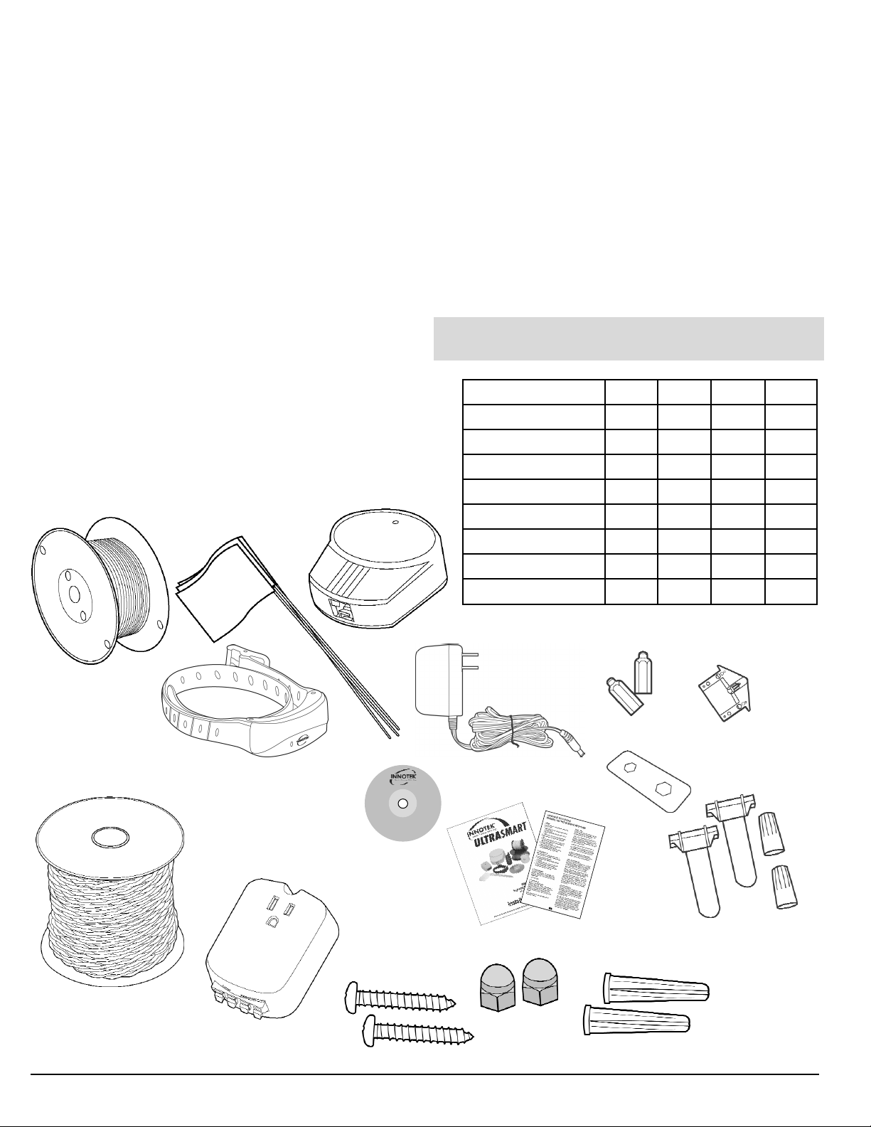
SSyysstteemmss CCoommppoonneennttss::
AAbboouutt UUllttrraaSSmmaarrtt IInn--ggrroouunndd PPeett FFeenncciinngg
SSyysstteemmss::
Easy-to-install in-ground fencing is great for any sized dog. You
design the configuration to keep your dog safely at home, but
clear of out-of-bounds areas such as gardens, ponds, and
pools. Patented run-through prevention offers secure and
reliable containment. Only UltraSmart’s ReadyTest
™
tells you
when the collar receiver is properly fitted on your dog and
working properly. The audible click sound from the collar
receiver assures you of perfect receiver contact with your dog’s
skin, and that the fit is neither too snug or too loose —
Ready Fit
™
— an INNOTEK exclusive feature!
Other than in the Installation Overview section, text with gray
background like this indicates
iimmppoorrttaanntt iinnffoorrmmaattiioonn
for you.
2 UltraSmart Pet Fencing Installation and Owner’s Manual
500’ Boundary Wire
Transmitter
Training Flags
AC Adapter
Test Light
Long Contacts
FasTrak
™
Pre-Twisted Wire
LP-4100 Lightning Protection Module
Waterproof Splices and Wire Nuts
Installation Manual — Training &
Troubleshooting Guide
Training DVD
Mounting Screws
Wall Anchors
Black Plastic
Training Contacts
These drawings are not to scale. They are provided here for identification purposes only.
MMaajjoorr SSyysstteemm CCoommppoonneennttss IIUUCC--44110000 IIUUCC--44220000 IIUUCC--55110000 IIUUCC--55220000
Transmitter
••••
FastTrak™Pre-twisted Wire
•••
UltraSmart collar
•• •
Contain N Train collar
•
Contain N Train Remote
•
Zones®Transmitter
•
LP-4100
•
Training DVD
••••
Contact Wrench
Rechargeable Collar Receiver

IImmppoorrttaanntt IInnffoorrmmaattiioonn
1. Read the complete manual and follow all directions,
including the enclosed
If you have any questions, please call 1-800-826-5527.
2. This device is intended for use only on dogs. Never attempt
to use it for any purpose not described in this manual.
3. Keep out of the reach of children.
4. Never perform set-up procedures while the collar receiver is
on your dog.
5. Any collar receiver worn for extended periods can cause a
condition similar to bedsores, known as Pressure Necrosis.
To reduce the possibility, you must do the following:
• Never leave the collar receiver on the dog for more than 12
hours per day.
• Check the fit to prevent excessive pressure; you should be
able to insert one finger between the collar strap and your
dog’s skin.
• Examine the dog’s neck daily for any signs of a rash or sores.
• Wash the dog’s neck area and the contacts of the collar
receiver weekly with a damp cloth.
• If the condition (described in #5) persists beyond 24 hours,
see your veterinarian.
6. Other collars and metal tags should be removed as they
may interfere with proper operation.
7. Do not attempt to dismantle or repair any components of
this system; doing so will void the warranty in full. The
computerized circuitry should be serviced only by an
authorized expert.
8. Realize that because dogs have unique temperaments,
there is no way of knowing how your dog will react to its
introduction to an in-ground pet fencing system. For the
safety of your dog, a long lead should be used during initial
training so you have control of the situation.
9. If you have reason to believe that your dog may pose a
danger to others, harm itself, or react adversely to the collar
receiver, do not rely solely on this product to train your dog.
If your dog shows signs of growling, snarling, or biting while
using the collar receiver, stop immediately. Aggression in
dogs has many causes. We recommend that you consult a
knowledgeable professional dog trainer or animal
behaviorist experienced with aggressive dogs if your dog
has shown any of these characteristics.
10. Occasionally, a dog cannot be trained to respond to an inground fencing system’s collar receiver. Sometimes even a
properly-trained dog may disobey a command. Therefore,
INNOTEK
that the system will, in all cases, keep the customer’s
animal from disobeying commands.
11. If the pet fencing system should stop working, find an
alternate method to protect your pet and call our Consumer
Services department at 1-800-826-5527 to determine the
cause and appropriate remedy to repair the system.
®
, its distributors, and its dealers cannot guarantee
Training and Troubleshooting Guide
®
This INNOTEK
forth by United States telecommunications authorities. Note that
in some countries, use may be limited due to national frequency
.
planning requirements. The user is responsible for respecting
those rules.
product is designed to meet requirements set
WWee ccaarree.. CCaallll uuss ffiirrsstt..
11--880000--882266--55552277
LLiimmiitteedd LLiiffeettiimmee WWaarrrraannttyy
Invisible Technologies, Inc. warrants to the original retail
purchaser, that INNOTEK
defects in material and workmanship, under normal use, for a
period of one year from the date of the original retail purchase.
This Limited Warranty excludes: accidental damage due to dog
chews; lightning damage where an INNOTEK lightning
protection component is not in use (in-ground pet fencing
systems); or neglect, alteration, or misuse.
INNOTEK offers several product exchange options during the
warranty period. If service is required, call 1-800-826-5527 to
discuss the service plan that best serves your needs. Proof of
purchase is required. Costs are dependent on the processing
time and the desired shipping options. Please do not return this
product to your retailer.
After one year from date of original retail purchase, we will
repair, replace, or upgrade your product at a fixed rate based
on the component.
Invisible Technologies, Inc., shall not be liable or responsible for
any incidental or consequential damages resulting from the use
of the product or caused by any defect, failure, or malfunction
of the product, whether a claim is based upon warranty,
contract, negligence, or otherwise.
FREE Professional Training Support
Looking for the best way to get a well-behaved dog?
Just call our FREE Professional Training Support hotline
®
brand products will be free from
Additional behavior or training issues?
1-800-364-3362
RReeggiisstteerr YYoouurr PPrroodduucctt
Your product can be registered on our website at
www.innotek.net
Note: Features & Specifications are subject to change without
notice.
®
INNOTEK
omissions in this manual or on its packaging. To check for
updates to this manual, visit our website at www.innotek.net.
is not responsible for unintentional errors or
UltraSmart Pet Fencing Installation and Owner’s Manual 3
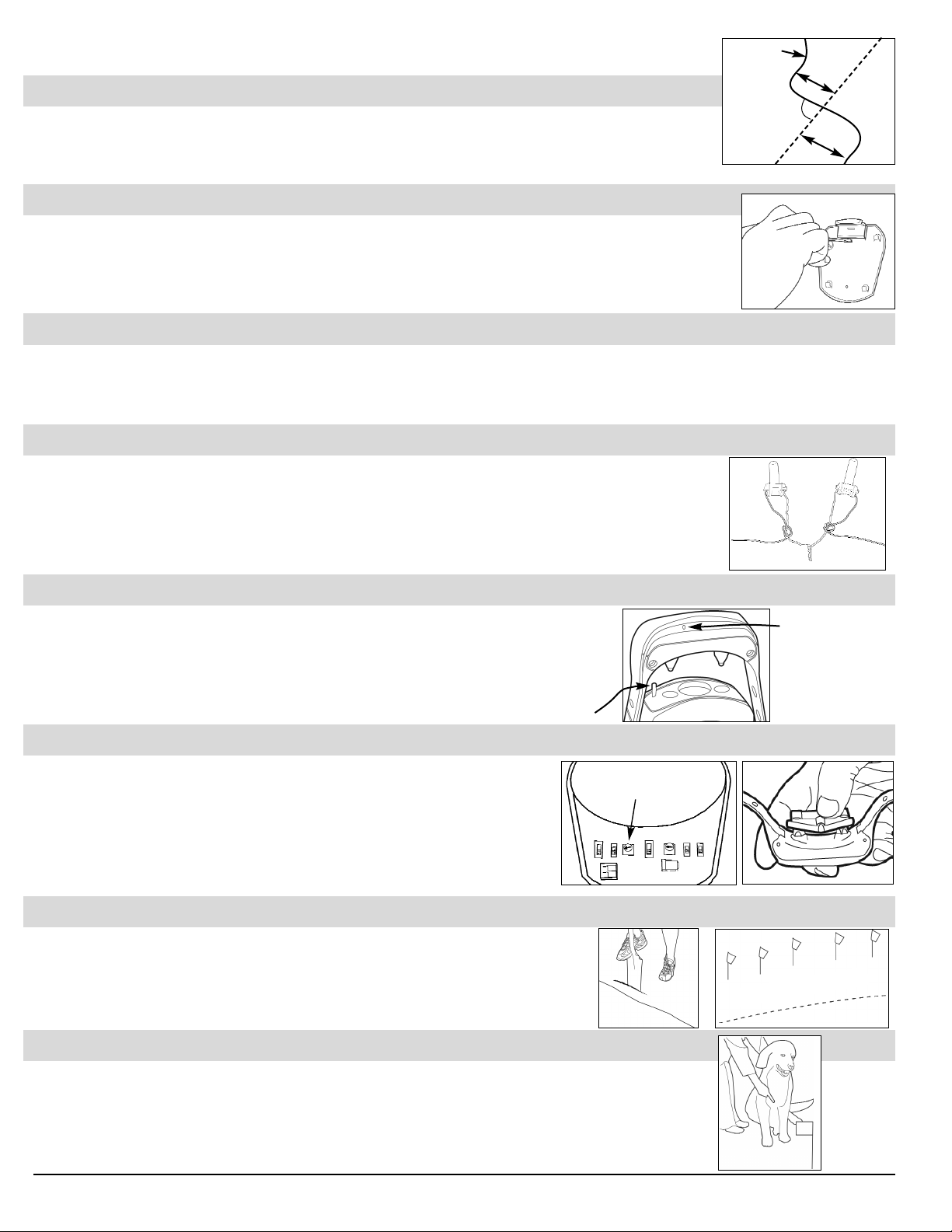
Installation Overview (all of these steps are explained with more detail in this manual)
SStteepp 11 DDeessiiggnn YYoouurr CCoonnttaaiinnmmeenntt AArreeaa
Have your local utility companies mark all your underground utility lines. Draw a sketch of your house
and yard. Draw a line around your property that represents the desired fencing area. Always cross
buried utility lines at 90° angles as shown.
SStteepp 22 IInnssttaallll tthhee TTrraannssmmiitttteerr
Most people find the inside of an exterior garage or basement wall an ideal transmitter location. You will
need a 110VAC grounded outlet within 5 feet for power. Using the screw holes in base of the transmitter
as a template, mark location of holes with a pencil. Attach transmitter base to the wall using supplied wall
anchors and mounting screws. Place transmitter onto the mounting plate.
SStteepp 33 LLaayy OOuutt tthhee FFeennccee WWiirree
Route the boundary wire around your property as sketched in your plan. Route twisted wires from the transmitter to outside where
they connect to the boundary loop. Either run the twisted wires through a window, or you can drill a ¼” hole at the base of the wall
to pass the twisted wires through. (After final installation and testing is complete, you can caulk the hole to keep it weathertight.)
SStteepp 44 MMaakkee BBoouunnddaarryy WWiirree CCoonnnneeccttiioonnss
TThhiiss sstteepp iiss vveerryy iimmppoorrttaanntt..
Please
rreeaadd ppaaggee 99
for detailed instructions on making splices. Connect the
boundary loop wires to the twisted wires using the supplied wire nuts and waterproof splices. Connect the
other end of the twisted wires to the transmitter’s LOOP connector. Plug in the AC adapter into a nearby
110VAC outlet. Connect the AC adapter cable to the transmitter, and turn on the transmitter. The
transmitter’s green light should come on to show that the boundary loop and all splices are good.
SStteepp 55 CChhaarrggee CCoollllaarr RReecceeiivveerr
Plug the Charging Cradle into a 110VAC outlet. Place the Collar Receiver on the charging
cradle (as shown at right). Proper placement is important for charging the receiver, be sure
that the charging cradle pin touches the charge contact of the Collar Receiver (more
details are elsewhere in this manual).
SStteepp 66 TTeesstt tthhee BBoouunnddaarryy WWiirree SSiiggnnaall
Start with your Field Width Adjustment Control set to the 9 o’clock position.
Place the test light onto the receiver contacts as shown at far right, and walk the
collar receiver up to the boundary wire. Listen for the warning tone, and look for
the test light to light up. Do not touch the receiver contacts. Try a number of
different places around the boundary area to verify the field width is consistent
(see page 10).
SStteepp 77 BBuurryy FFeennccee WWiirree
Make a trench 3” deep with a flat-edge spade or use a gas-powered edger. Making
the trench at an angle helps keep the boundary wire in the ground as you place it.
Repeat Step 6 and place flags at the inside edge of selected boundary field where the
warning tone is first heard, NOT right at wire.
SStteepp 88 TTrraaiinn YYoouurr DDoogg
Watch the included training DVD and follow the training steps outlined in the separate
Training and
Troubleshooting Guide
. Your dog may respond immediately to the training, however, continue to follow
the training instructions to fully train your dog. The convenience that your new in-ground pet fencing
offers, plus the added safety for your dog, are well worth the time invested.
4 UltraSmart Pet Fencing Installation and Owner’s Manual
Boundary Wire
10’
10’
Buried Cable
90°
Field Width
Adjustment Control
Collar receiver light
glows red when
properly placed on
the Charging Cradle.
Inside the Boundary Field
Splices
Boundary
Wire
To Transmitter
This pin touches the charge
contact of the Collar Receiver.
Boundary
Wire
TToooollss ffoorr IInnssttaallllaattiioonn
You will need the following tools to install your fencing system:
• drill with drill bits • screwdriver
• wire strippers • flat edge spade or optional gaspowered edger (many rental centers carry these for a
reasonable time-based fee).
Depending upon your particular installation, you might need:
• hammer
• silicone caulk
• circular saw with masonry blade
• sections of PVC pipe, or a length of garden hose.
HHooww tthhee SSyysstteemm WWoorrkkss
There are three parts to an In-ground Pet Fencing System:
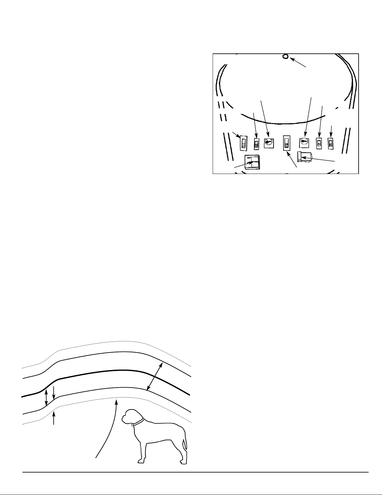
FFaammiilliiaarriizzee YYoouurrsseellff wwiitthh TTrraannssmmiitttteerr CCoonnttrroollss
The Transmitter is the fencing system’s control center. The front
cover lifts to reveal these switches and controls that customize
your system.
TTrraannssmmiitttteerr CCoonnttrroollss
10. Indicator Light
1. Field Width Adjustment
2. Field Size Switch
3. Stimulation
Level Switch
9. Alarm Volume Control
8. ON/OFF Switch
7. Battery
Backup Monitor
Switch
TTrraannssmmiitttteerr
1. The
sends a coded radio signal through the
boundary loop wire.
BBoouunnddaarryy LLoooopp WWiirree
2. The
is waterproof insulated wire. You
bury it in the yard and connect it to the Transmitter. This makes
the boundary that your dog has to stay inside, and not cross.
Twisted wires are used to get the signal from the Transmitter to
the boundary wire. Twisted wire cancels the signal to the
receiver, providing a safe, signal-free area in which your dog
can play.
3. Your dog wears the
CCoollllaarr RReecceeiivveerr
. The receiver picks up
the coded radio signal when it gets within a pre-determined (by
you) distance from the buried boundary wire. When at the
inside edge of the boundary field, the collar receiver gives off a
warning tone. When the collar receiver goes further into the
boundary field, an annoying correction is delivered, and the dog
returns to the safe part of the yard. With proper training, your
dog learns to stay within the boundary of the containment area.
4. Loop Wire
Terminals
FFiieelldd WWiiddtthh AAddjjuussttmmeenntt
1.
5. Collar Receiver Charge Reminder
- Controls how close your dog can
get to the boundary wire before hearing the warning tone.
FFiieelldd SSiizzee SSwwiittcchh
2.
SM) for installations of less than 1000 feet of boundary wire.
(
Move this switch to large (LG
- Your Transmitter is factory-set to small
) for installations of 1000 feet of
wire or more.
SSttiimmuullaattiioonn LLeevveell SSwwiittcchh
3.
- Select from Stimulation levels
Low, Medium, or High. This is the stimulation level your dog
feels after a 2-second warning tone (Low and Medium
selections only). The warning tone and stimulation are
delivered at the same time when the stimulation level switch
is set to High.
LLoooopp WWiirree TTeerrmmiinnaallss
4.
- The boundary loop wire connects to
these spring-loaded connectors.
CCoollllaarr RReecceeiivveerr CChhaarrggee RReemmiinnddeerr
5.
- This feature is not used
with UltraSmart In-ground pet fencing systems, so set to
6. Power
Connection
(PWR)
OFF. The collar receiver status light lets you know the
charge level of the collar receiver’s internal battery.
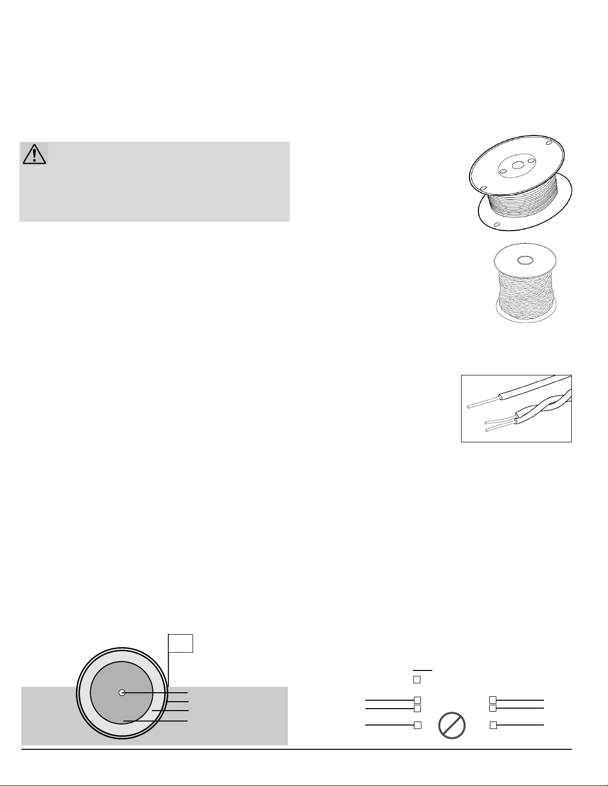
TThhee CCoorrrreeccttiioonn ZZoonneess AArroouunndd tthhee BBoouunnddaarryy WWiirree
((
vviieewweedd ffrroomm aabboovvee))
PPWWRR
6.
Power Connection - Power for the containment
system supplied by the AC adapter plugged into nearby
110VAC outlet.
Outside edge of Boundary field.
ttteerryy BBaacckkuupp MMoonniittoorr
BBaat
7.
- If power is interrupted to the
system, batteries keep the system working for up to 40
hours. Eight AA alkaline batteries (not included) provide
2/3 Field
Width
Buried Boundary Wire
Run-through
Correction
Width
ld
Fie
3
/
1
prevention
delivered
delivered
in thi
inth
szone
Inside edge of Boundary field.
iszone
backup power. The Battery Backup Monitor beeps once
per second and flashes an amber transmitter light when
batteries need to be replaced. When operating on battery
power, the transmitter beeps once every 5 seconds with no
light. For the safety of your dog, the Battery Backup Monitor
should be turned on at all times.
OONN//OOFFFF SSwwiittcchh
8.
AAllaarrmm VVoolluummee
9.
- Power up/power down the system.
- Alarm volume adjustment (this can not be
used to silence the alarm).
IInnddiiccaattoorr LLiigghhtt
10.
- The light on the front of the transmitter
indicates transmitter status. Refer to the table on the back
Warning Tone sounds at the
edge of Boundary field.
UltraSmart Pet Fencing Installation and Owner’s Manual 5
cover of this manual for detailed Transmitter status indicator
light information.
CCoollllaarr RReecceeiivveerr FFeeaattuurreess
Your dog wears the sleek waterproof collar receiver. The
receiver sounds the warning tone and gives an annoying
sensation should your dog attempt to leave the yard. Your collar
receiver is rechargeable, and is recharged by placing the collar
receiver on the charging cradle (plugged into a 110v AC outlet).
More information about recharging the collar receiver is found
later in this manual.
Important Notes:
• A small amount of hair thinning makes collar receiver contact with the
dog’s skin easier. Never shave hair from the dog’s neck.
• This product is recommended for dogs six months of age and older.
• Occasionally, check the tightness of the receiver contacts.
OOvveerr--SSttiimmuullaattiioonn PPrreevveennttiioonn
In the unlikely event that your dog refuses to leave the
Correction zone, the Over-Stimulation Prevention feature limits
stimulation duration to 10 seconds. The system shuts off for 10
seconds before resuming stimulation for another 10 seconds.
This pattern will repeat for a maximum of three cycles, a
duration of 60 seconds.
The light on the collar receiver will pulsate red when stimulation
is delivered, appear solid green when stimulation is locked out,
and flash yellow if the 60 second Over-stimulation period has
expired and the dog remains in the correction zone.
RRuunn--TThhrroouugghh PPrreevveennttiioonn
Special features are incorporated in the system so your dog
cannot “run-through” the boundary field without activating a
strong stimulation. The collar receiver automatically increases
the stimulation level when your dog continues more than 1/3 of
the way through the boundary signal field, regardless of the
transmitter stimulation level switch setting. For example, if the
signal is detected 12 feet from the wire and your dog enters the
boundary field, this feature is activated when your dog is
approximately eight feet from the boundary wire. At this point,
your dog automatically receives the highest level of stimulation.
Refer to the table on the back cover for detailed status indicator
light information.
BBoouunnddaarryy WWiirree aanndd TTwwiisstteedd WWiirreess
Your In-ground pet fencing system includes 500 feet of
boundary single wire. IUC-4200, IUC-5100, and IUC-5200
systems include a 100 feet spool of pre-twisted FasTrak
™
wire.
For larger fencing areas, kits of extra boundary wire, waterproof
splices, and convenient FasTrak pre-twisted wire are available
from your retailer, or call INNOTEK at 1-800-826-5527.
SSiinnggllee wwiirree
forms the biggest part of
the boundary. The radio signal is
transmitted along the single wire (see
diagram below left). Anywhere a single
wire is used as part of the boundary,
in a
ccoonnttiinnuuoouuss
loop, the radio signal
is active and the collar receiver will
respond to the radio signal.
TTwwiisstteedd wwiirree
is essentially two single wires
twisted together. Twisting wires together
hides the radio signal from the receiver
collar. Anywhere twisted wire is used, the
radio signal is not active, and the collar
receiver will not respond to it. Both wires of
twisted wire cannot be connected to a
single wire. Each wire in twisted wire
mmuusstt bbee
connected to a
single wire with a waterproof splice.
If you choose, you can make your
own twisted wire:
1. Cut two equal lengths of
boundary wire and hold them
side by side.
2. Insert one end of the two wires into a variable speed power
drill.
3. Anchor the other end of the two wires to something secure
or have a helper hold onto them.
4. Pull wires taught and run the drill slowly. You will see the
wires twisting together. Keep twisting until you have one
twist per inch.
The drill enables you to twist the wire quickly, however, you can
twist the wire manually if you wish. Make sure you end up with
at least one twist per inch.
DDiiaaggrraamm ooff RRiigghhtt aanndd WWrroonngg TTwwiisstteedd WWiirree UUssee::
6 UltraSmart Pet Fencing Installation and Owner’s Manual
FasTrak™Pre-Twisted Wire
500’ Boundary Wire (Single wire)
Twisted Wires
Boundary Wire
XXXXX
= Twisted Wires
= Boundary Wire
= Waterproof Splice
XXXXXXXXXXXXXXXXXXXXXXXXXXXXXXXX
XXXXXXXXXXXXXXXXXXXXXXXXXXXXXXXXXX
Correct Wiring
of Twisted Wires
This is WRONG!
Buried Boundary Wire
Warning Tone Zone
Correction Zone
Run-Through Prevention Zone
Place Training Flags where
Warning Tone is first heard.
Outside the
Boundary Wire
Inside the Boundary Wire
DDiiaaggrraamm ooff CCoorrrreeccttiioonn ZZoonneess..

SSiittee PPrreeppaarraattiioonn -- DDeessiiggnn tthhee
11
FFeenncciinngg AArreeaa LLaayyoouutt
The first thing you need to do is have your local utility
companies mark all underground utility lines on your property.
Next, figure out where you want your dog to be able to go and
where you want your dog to be kept out. It’s very helpful to
make a sketch of your property, showing your house and any
existing barriers (like fences, shorelines, etc.). In your sketch, be
sure to include special areas you want your dog to stay out of,
like gardens, ponds, and swimming pools.
Draw a single line (representing
the fencing area for your dog)
around your property. Always
cross buried utility lines at 90°
angles as shown.
If you have additional areas you
want the dog to avoid, draw a line around these areas.
Some typical installation diagrams are shown in the Appendix
starting on page 16. Right after the typical installation diagrams,
you’ll find installation instructions for each of them.
IImmppoorrttaanntt::
• Although the boundary wire will be buried only 1” to 3”, make
sure you contact your utility companies to mark underground
cables, wires, and other utilities before you dig.
• Signal coupling can occur around large metal objects and
buried electrical, telephone, cable TV, low voltage lighting
wires, and undergournd sprinkler systems. Do not run
boundary wire closer than 10’ from or parallel to any utility
lines. If the fencing boundary signal couples onto utility lines,
you can end up with unwanted boundary signals inside the
safe part of the yard, or inside the house. You can minimize
coupling by crossing perpendicular (90°) to these utility lines.
• Due to the inherent properties of radio signals, some
locations may affect the maximum range that can be
achieved. This may be particularly noticeable around metal
objects.
• The boundary wire must form a complete, continuous loop
from the transmitter.
• For your dog’s safety, it is recommended that you keep the
boundary wire at least 10’ from the street.
• Keep in mind that you will place the wire to allow for an 6’ to
12’ boundary signal field width, measured from the wire.
Boundary Wire
10’
Buried Cable
90°
10’
TTyyppiiccaall IInnssttaallllaattiioonn DDiiaaggrraammss
Look through the typical installation diagrams in the Appendix
(starts on page 16) so you can get an idea of how you’d like to
install your system on your property.
Decide where the Transmitter is going to be installed. More
often than not, it is located inside an exterior garage wall or on a
basement wall. Usually, you’ll want to install twisted wires
between the Transmitter and the boundary wire. Some people
use a window opening, while others choose to drill a small ¼”
hole at the base of the wall to run the wires through, then caulk
the hole to keep it weather-tight. For now, though, you’re just
sketching your planned installation.
Use twisted wires between the Transmitter and the boundary
loop wire. This allows the signal to continue traveling through
the wires, but keeps the signal from activating the dog’s collar
receiver. Another reason to use twisted wire between the
Transmitter and the boundary loop wire is to keep from having
an active boundary signal near the Transmtter. (Without using
twisted wire: If the Transmitter is installed on a garage wall, and
your dog is in the garage wearing the collar receiver, the collar
receiver could possibly react to the signal.)
The boundary signal starts at the Transmitter and goes out to
the boundary loop wire, all around the property, and then
comes back to the Transmitter to complete the circuit. If this
“loop” develops a break, the boundary signal stops working,
and your dog can roam freely.
If you run straight boundary wire out to the boundary loop (you
choose to not use twisted wires between the transmitter and
the boundary loop), your dog won’t be able to pass over the
part of the yard where the wires go out to the boundary wires.
The boundary signal acts like a wall there, just like it does
around the property.
Review the Typical Installation diagrams and then draw your
sketch of how you want to install your pet fencing system.
These diagrams might give you ideas for your property sketch.
Following the Typical Installation diagrams, you’ll find instructions
for installing each of them. These provide additional education
on various installation techniques for pet fencing.
After you’ve made your sketch of how you want to install your
pet fencing system, continue to Step 2.
UltraSmart Pet Fencing Installation and Owner’s Manual 7
22
IInnssttaallll tthhee TTrraannssmmiitttteerr
SSeelleecctt aa TTrraannssmmiitttteerr LLooccaattiioonn
Select a dry indoor location to install the Transmitter. Avoid
areas that have large metal appliances (refrigerators, freezers,
electrical panels, etc.). Large metal objects may interfere with
the boundary signal. You will need a 110VAC grounded outlet
within 5 feet for transmitter power. Most people find the inside
of an exterior garage wall or basement wall works well. You will
need an easy way to run the boundary wire to outside.
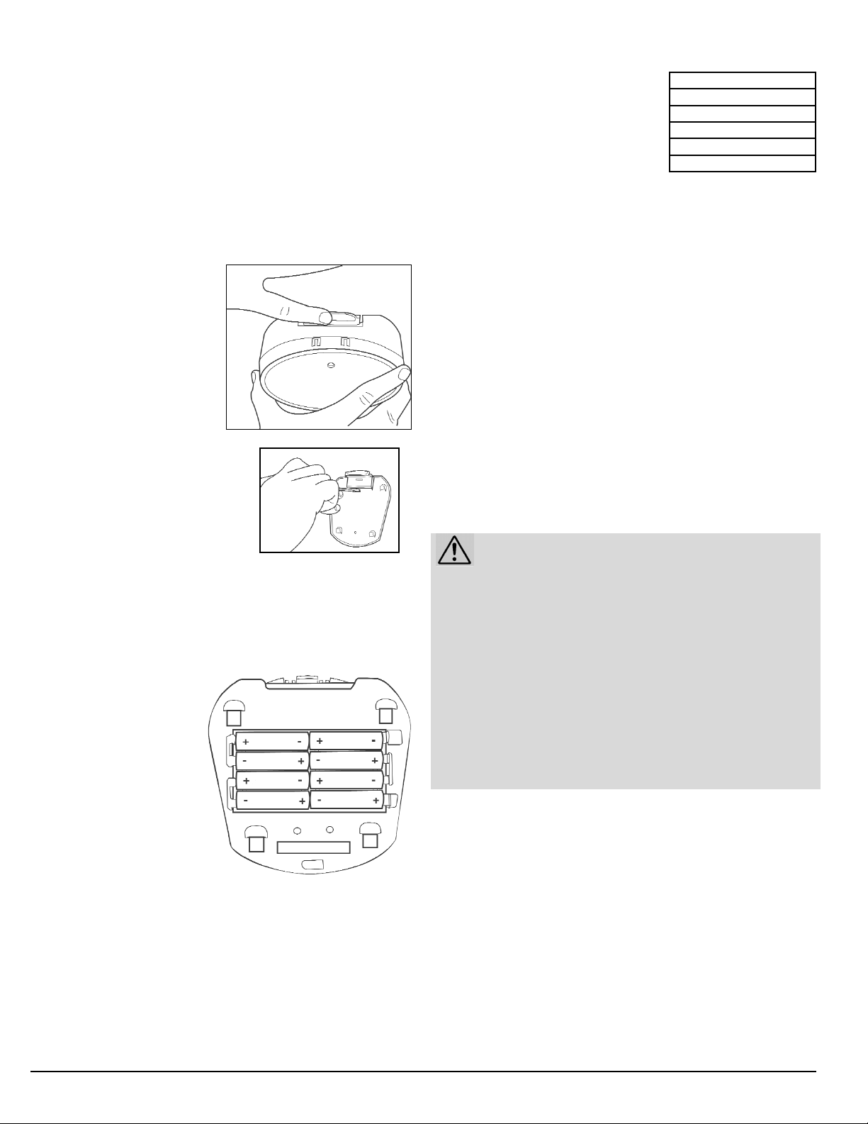
IInnssttaallll tthhee MMoouunnttiinngg PPllaattee
The mounting plate is attached
to the back of the transmitter.
Remove by lightly pressing the
dot on the top tab and sliding
the transmitter assembly up
from the plate.
Using the mounting plate as a
template, mark hole locations on
the wall.
For hollow wall installation, drill ¼”
holes into the wall. Insert wall
anchors (no metal inside; if you see
metal inside, you’ve got the wire
nuts) into the ¼” holes (lightly tap
into holes with a hammer). Use a screwdriver to fasten the
mounting plate to the wall with supplied mounting screws.
For installation directly into a wall stud, drill 3/32” diameter pilot
holes at the marked locations. Fasten with supplied screws.
IInnssttaallll BBaacckkuupp BBaatttteerriieess
(Optional, but strongly recommended)
In case of a power failure, the
system can run for up to 40
hours on 8 AA batteries (not
included). Remove the
transmitter from the mounting
plate and install batteries into
the battery holder. Replace the
transmitter onto the mounting
plate. Set the Battery Backup
Monitor switch to the ON position. If
you choose to not use the battery backup, set the Battery
Backup Monitor switch to the OFF position.
PPrroovviiddee WWiirree AAcccceessss BBeettwweeeenn TTrraannssmmiitttteerr aanndd
BBoouunnddaarryy LLoooopp
You will need to get twisted wires between the transmitter and the
boundary loop. Either use a window opening, or drill a ¼
”
hole at
the base of the wall to pass wires through. From the inside, drilling
at a slight downward angle will help keep rainwater out. After final
testing is complete, caulk the hole to keep it weather-tight.
33
LLaayy OOuutt tthhee BBoouunnddaarryy WWiirree
AAmmoouunntt ooff WWiirree
Your fencing system includes 500
feet of boundary wire. Some systems
also include 100 feet of pre-twisted
FasTrak
™
wire. For larger in-ground pet fencing areas, kits of
extra boundary wire, waterproof splices, and convenient
FasTrak pre-twisted wire are available from your retailer, or call
INNOTEK at 1-800-826-5527. Refer to the table at upper right
for determining how much wire you will need.
PPllaacciinngg tthhee WWiirree iinn tthhee YYaarrdd
The boundary wire must make a continuous loop from the
transmitter, out around the desired fencing area, and back to
the transmitter. Keep in mind that you will want a 6’ to 12’
boundary signal field width from the wire. Don’t run the wire too
close to the house, and don’t make passageways too narrow
for your dog to get through (unless planned that way). You may
need temporary anchors (like tent stakes) for the wire while
laying it out. Follow your sketch.
RRoouunnddiinngg CCoorrnneerrss
Use gradual turns at corners with a minimum radius of 2½ feet.
This will produce a more consistent boundary signal.
IMPORTANT TIPS!
• DO NOT run wire within 10 feet or parallel to cable TV,
phone, and electrical lines. The signals can couple together
causing collar receiver activation inside the house and in the
safe parts of the yard.
• The wire must form one continuous loop from the transmitter.
• Use twisted wire to run between the transmitter and interior
loops around pools and gardens to allow your dog to safely
pass around these areas (refer to diagrams in Appendix).
• Work carefully. Any nick in the wire can diminish signal
strength and create a "weak" area with the potential for your
dog to escape.
8 UltraSmart Pet Fencing Installation and Owner’s Manual
Acres Linear Feet Needed
1 850
2 1200
3 1500
4 1700
5 1900
Back of Transmitter
WWiirriinngg CCoonnnneeccttiioonnss
44
CCoonnnneeccttiinngg ttoo tthhee BBoouunnddaarryy WWiirree
Splice the ends of the twisted wire to the ends of the boundary
wire with the supplied waterproof splices. Only use waterproof
splices supplied by INNOTEK. Additional splices are available
by calling 1-800-826-5527. Use of wire nuts alone, electrical
tape, or solder will not provide a secure waterproof connection
(required for your system to work properly).
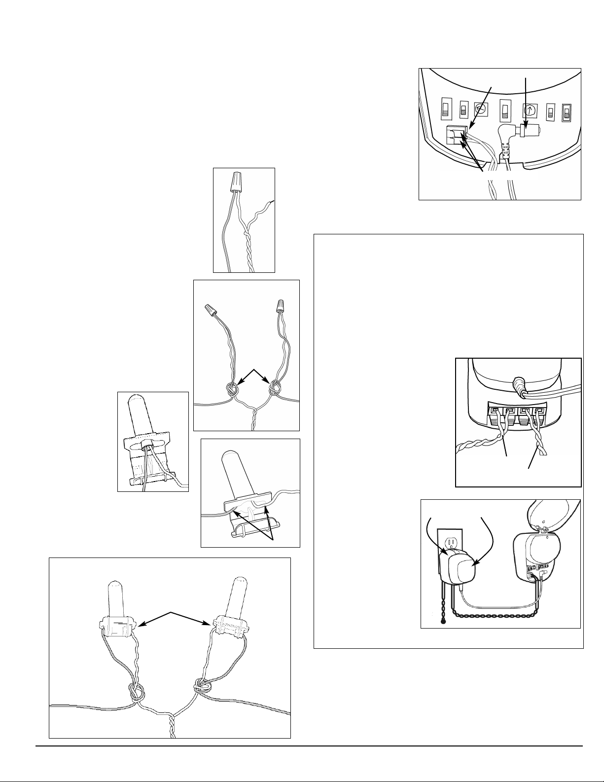
UUssiinngg tthhee WWaatteerrpprrooooff SSpplliicceess
1. Strip ½” of insulation from wire ends.
Hold one twisted wire end and one
boundary wire end together. Insert
them into a wire nut and twist the wire
nut clockwise until tight. Repeat for
the other twisted wire end and the
other boundary wire.
2. Tie a simple knot in the wires
around 5 to 6 inches from the
wire nut. This prevents the wires
from pulling free during later wire
burial.
3. Insert wire nut into the splice.
4. Push the wire nut all the way into
the waterproof
gel. Avoid
getting gel on
your hands, it’s
difficult to
remove.
Spread the
wires apart
where the wires come out of the
splice as shown.
5. Snap the lids shut on both splices.
5
Waterproof Splice
3
Lids closed on both
2
Wire nut
Boundary
Wire
Wire nut goes all the way in.
4
Spread wires out the openings.
Waterproof Splice
Wire nut
1
Knots
Twisted Wires
Wire nut
Boundary
Wire
CCoonnnneeccttiinngg WWiirreess ttoo tthhee TTrraannssmmiitttteerr
1. Strip ½” of insulation from both twisted wire ends. Lift the
tabs on top of the wire terminals marked “LOOP” on the
transmitter and
insert one wire into
each connector.
Release the tabs.
2. Plug the supplied
AC adapter into a
nearby household
110VAC outlet.
3. Route the AC
adapter cable to
the transmitter. Plug the AC adapter cable into the
transmitter’s power connector (marked “PWR”).
LLiigghhttnniinngg PPrrootteeccttiioonn MMoodduullee LLPP--44110000
Some systems include a lightning protection module, which
helps protect the transmitter from electrical power surges and
lightning strikes near your boundary wire loop. A nearby
lightning strike can cause failures due to high voltage damaging
your transmitter. Lightning protection is available by calling
1-800-826-5527. Lightning damage is not covered under the
warranty unless you use the INNOTEK LP-4100.
1. Strip ½” of insulation from
the twisted wires coming
from the boundary loop and
connect into the LP-4100
connector marked “LOOP.”
2. Strip ½” of insulation from
both ends of a short piece
of twisted wires. Insert one
pair into the terminals
marked “Transmitter” on the
LP-4100. Connect the
remaining end to the “Loop”
terminals on the transmitter.
3. Plug the LP-4100
into a nearby
110VAC outlet.
4. Plug the transmitter
AC adapter directly
into the AC socket
of the LP-4100.
5. Route the AC
adapter cable to the
transmitter. Plug the
AC adapter cable
into the transmitter’s
power connector (marked “PWR”).
Raise these Tabs to insert wires.
LP-4100 AC Adapter
To Outdoor Boundary Wire Loop
Power Connector
Loop Connectors
AC Adapter
LP-4100
Boundary Loop Wires
Twisted Wires to Transmitter
“LOOP” connector.
PPoowweerr UUpp tthhee TTrraannssmmiitttteerr
Knot
Boundary Wire
UltraSmart Pet Fencing Installation and Owner’s Manual 9
Twisted Wires
Knot
Boundary Wire
1. Move the transmitter’s power switch to the ON position.
2. The transmitter’s green indicator light should come on,
indicating a properly connected boundary loop. If the light
does not come on, or an alarm sounds, refer to the tables
on the back cover, and the included
Troubleshooting Guide
.
Training &
 Loading...