


SG-2020
Transceiver
Installation and Operations Manual
“No Compromise Communications”

SGC — The SSB People
SGC develops, manufactures, and sells high performance single sideband (SSB) communications equipment. Since 1971, the company has sold to the marine, military, aviation, and industrial markets world wide. Over these years, SGC has earned an outstanding reputation for product reliability and for service after sale.
The company keeps pace with equipment options, engineering developments, and design requirements. Its products are the most competitive in the entire long distance communication market. SGC equipment is presently being used by the United Nations for inter-communications in developing countries throughout the world. Many competitive racing vessels, as well as fishing boats, tugs, and commercial craft are equipped with SGC equipment. In fact, an SGC radiotelephone provided the only communications available on a past Polar expedition by the National Geographic Society.
SGC also supplies U.S. government agencies, several foreign governmental agencies, and major petroleum companies through Asia and latin America.
All SGC equipment is designed and manufactured in the USA. SGC has qualified people ready to provide technical information, assistance in selecting equipment, and recommendations for any installation.
SGC welcomes your call to discuss your SSB requirements.
SGC 2020 Staff
2
© 1998 SGC Inc
SGC Inc. SGC Building, 13737 S.E. 26th St. Bellevue, WA. 98005 USA
P.O.Box 3526, 98009 Fax: 425-746-6384 or 746-7173 Tel: 425- 746-6310 or 1-800-259 7331 E-mail: sgc@sgcworld.com Web site: http://www.sgcworld.com

SG-2020
Transceiver
Installation and Operations Manual
“No Compromise Communications”
Manual Version 2.01
Software Version 1.06
July 1999
SGC RESERVES THE RIGHT TO MODIFY SPECIFICATIONS WITHOUT NOTICE.
i
SGC Inc. SGC Building, 13737 S.E. 26th St. Bellevue, WA. 98005 USA
P.O.Box 3526, 98009 Fax: 425-746-6384 or 746-7173 Tel: 425- 746-6310 or 1-800-259 7331 E-mail: sgc@sgcworld.com Web site: http://www.sgcworld.com
© 1998 SGC Inc.
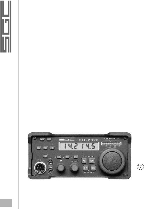
TABLE OF CONTENTS
1.0 |
FEATURES |
PAGE |
1 |
||
2.0 |
INTRODUCTION |
2 |
3.0 |
SPECIFICATIONS |
4 |
4.0 |
INSPECTION UPON RECEIPT |
5 |
5.0 |
MODES OF OPERATION |
5 |
6.0 |
INSTALLATION |
8 |
7.0 |
SG-2020 APPLICATIONS |
12 |
8.0 |
FRONT PANEL |
17 |
9.0 |
SECONDARY SWITCH FUNCTIONS |
21 |
10.0 |
POWER ON OPTIONS |
23 |
11.0 |
BARGRAPH DISPLAY |
25 |
12.0 |
FRONT PANEL CONNECTORS |
26 |
13.0 |
REAR PANEL CONNECTORS |
27 |
14.0 |
CIRCUIT DESCRIPTION |
29 |
15.0 |
AM BROADCAST RECEPTION |
31 |
16.0 |
QUICK TOUR OF USER CONNECTORS |
33 |
17.0 |
ALIGNMENT / TEST PROCEDURES |
36 |
18.0 |
EXCITER VOLTAGE MEASUREMENTS |
39 |
19.0 |
PCB LAYOUT AND SCHEMATICS |
45 |
20.0 |
CATALOG ITEMS |
66 |
|
GLOSSARY |
72 |
|
APPENDIX A |
76 |
SG-2020 Transceiver Front
ii
© 1998 SGC Inc
SGC Inc. SGC Building, 13737 S.E. 26th St. Bellevue, WA. 98005 USA
P.O.Box 3526, 98009 Fax: 425-746-6384 or 746-7173 Tel: 425- 746-6310 or 1-800-259 7331 E-mail: sgc@sgcworld.com Web site: http://www.sgcworld.com
1.0 FEATURES
The SG-2020 is a compact low power transceiver with the features and performance you expect in a modern full size transceiver.
•Strong, wide dynamic range receiver
•Selectivity at 2.7 KHz not less than 60 dB rejection on the adjacent channel
•RF Speech processing
•All Band Operation 160 mtrs through 10 mtrs.
•General Coverage Receiver, 1.8 MHz through 29.7 MHz
•Extended receive range from 400 kHz to 1600 kHz available
•20 memories that are fully user accessible
•Split, RIT / XIT capable
•High performance baseband selectable digital filters
•Single Sideband in USB and LSB
•Full break-in operation in CW
•Built in mode 'B' Iambic Keyer, adjustable from 5 to 60 WPM
•Very low power consumption on receive, less than 400 mA
•Frequency Scan
•Memory scan with adjustable dwell timing
•DC Volt meter
•Operational temperature range of -30 to +70º C
WARM-UP TIME
The SG-2020 is equipped with a thermistor resistor circuit designed to stabilize the frequency. A warm-up time of 15 to 30 minutes is needed to achieve full stability. The unit is fully operational during this time, but a drift of plus or minus 200 Hz may be noticed.
1
SGC Inc. SGC Building, 13737 S.E. 26th St. Bellevue, WA. 98005 USA
P.O.Box 3526, 98009 Fax: 425-746-6384 or 746-7173 Tel: 425- 746-6310 or 1-800-259 7331 E-mail: sgc@sgcworld.com Web site: http://www.sgcworld.com
© 1998 SGC Inc

|
2.0 INTRODUCTION |
|
|
Thank you for choosing the SGC Model SG-2020 transceiver. We |
|
|
know that you have many options when choosing your communica- |
|
|
tions equipment, and we are glad that your choice was SGC - an |
|
|
American designed and manufactured product. SGC has been man- |
|
|
ufacturing HF transceivers and equipment form 1971. Our philoso- |
|
|
phy is to bring unique design innovations to the industry; products |
|
|
that give superior performance and at very affordable prices. |
|
|
The SG-2020 is by no means just another radio amateur product. It |
|
|
is a professional, commercial grade transceiver, designed for a |
|
|
whole panorama of HF users - amateurs, professionals and others. |
|
|
The SG-2020 is the first in a series of new generation SGC products |
|
|
based on the single I.F. frequency. |
|
|
SGC introduced the first HF SSB which was mass produced for the |
|
|
marine industry. This product included new features, such as wide- |
|
|
band technology, all solid state and single conversion. This concept |
|
|
led to the cutting edge technology behind the SG-2020 transceiver |
|
|
with its intercept point at +18 dbm. Strong front end, single conver- |
|
|
sion, structured around an I.F. frequency of 60 MHz, provides for a |
|
|
superior and outstanding receiver with an IF rejection of 90db. |
|
|
Spurious frequencies typically generated by conventional multiple |
|
|
conversion designs are virtually eliminated. |
|
|
With a custom high performance SGC mixer, we keep the design |
|
|
simple and of superior performance. We have eliminated interfering |
|
|
circuitry found in other transceivers. An additional design goal was |
|
|
to have a low stand-by current, below 400 mA, which would allow |
|
|
this unique product to be used in many applications when others |
|
|
could not. |
|
|
The SG-2020 incorporates a very basic noise blanker circuit which |
|
2 |
||
operates without compromising receiver performance and without |
||
|
|
© 1998 SGC Inc
SGC Inc. SGC Building, 13737 S.E. 26th St. Bellevue, WA. 98005 USA
P.O.Box 3526, 98009 Fax: 425-746-6384 or 746-7173 Tel: 425- 746-6310 or 1-800-259 7331 E-mail: sgc@sgcworld.com Web site: http://www.sgcworld.com

any additional current drain. This allows excellent receiver characteristics to be preserved along with long battery life. We believe these benefits will be highly appreciated by operators in the field and other portable operations.
The rugged transmitter section provides exceptionally clear, clean audio, and provides excellent performance characteristics. The amplifier has the stress power capability of 40 watts. In other words, it is capable of producing 40 saturated watts in mid band and therefore, a rating of 20 watts PEP is very conservative.
The SG-2020 is equal to the performance of only a very few transceivers available in today's market and which cost several thousand dollars. We are very proud of this unit - its' features, performance and price. You check it out and let us know what you think.
3
SGC Inc. SGC Building, 13737 S.E. 26th St. Bellevue, WA. 98005 USA
P.O.Box 3526, 98009 Fax: 425-746-6384 or 746-7173 Tel: 425- 746-6310 or 1-800-259 7331 E-mail: sgc@sgcworld.com Web site: http://www.sgcworld.com
© 1998 SGC Inc

3.0 SPECIFICATIONS:
SG-2020 SSB HF TRANSCEIVER
GENERAL |
|
General Operating modes: |
USB, LSB and CW |
Receiver Frequency range: |
1.8 to 30.0 MHz, general coverage |
|
(400 kHz to 1600 kHz with broadcast filter bypassed) |
Transmit Frequency range: |
1.8 to 29.7 MHz (US Ham Bands only) |
|
1.8 to 30.0 MHz (general coverage, export) |
Operational Temperature |
|
Range: |
-30 to +70º C |
Operational Voltage Range: |
9 - 18 VDC |
Microprocessor: |
MC68HC711E9 |
Frequency Stability: |
3 ppm per 10º C *(see example below) |
Frequency Resolution: |
10 Hz |
Frequency Display: |
100 Hz |
RX / Tx Changeover: |
less than 10 ms |
Memories: |
20 (factory pre-set, user definable) |
Reflected Power Metering: |
built in |
LCD: |
back light selectable |
Keyer: |
fully adjustable IAMBIC mode 'B', 5 to 60 WPM |
Memory Scan: |
Adjustable |
Dimensions: |
2.75H x 6W x 7L |
Approximate weight: |
4.4 lbs. |
Microphone: |
fist, dynamic |
Battery Volt meter: |
digital; front-panel controlled |
RECEIVER |
|
Sensitivity: |
better than .5µV for 10dB S/N+N |
Intermodulation: |
+18 dbm 3rd order intercept |
Selectable AF bandpass: |
100Hz to 2700Hz |
Audio Output: |
1 watt RMS |
AF distortion at nominal |
|
output power: |
less than 3% |
Internal Speaker: |
5 watts maximum, 4 ohms |
Noise Blanker: |
pulse / ignition |
RF Gain: |
front panel controllable |
BFO: |
processor controlled |
Total power consumption: |
less than 400 mA (receive only) |
TRANSMITTER |
|
Output Power: |
nominal 1.8-25 MHz 20 watts PEP |
|
( above 25 MHz 14 watts min.) |
Output Power Adjustment: |
front panel control 1 to 25 watts |
RF Speech Processing: |
VOGAD baseband and rf clipping |
Transmit Current consumption: 4 amperes, typical at 20 watts PEP voice |
|
Transmit intermods, 20 watts: |
-28 dB or better |
Transmit Spurious: |
-50 dB (Ham Bands) |
Specifications listed represent optimal conditions and are not subject to warranty. All SGC products must be used with compatible equipment
|
*Example: at 14.2 MHz = 14.2 x 3 = 42.6 Hz; A total frequency drift of 42.6 Hz for a temperature change |
4 |
of 10º C. If the ambient temperature changes from 20º to 30º C, there could be a drift of 42.6 Hz. |
SGC reserves the right to modify specifications without notice. |
© 1998 SGC Inc
SGC Inc. SGC Building, 13737 S.E. 26th St. Bellevue, WA. 98005 USA
P.O.Box 3526, 98009 Fax: 425-746-6384 or 746-7173 Tel: 425- 746-6310 or 1-800-259 7331 E-mail: sgc@sgcworld.com Web site: http://www.sgcworld.com

4.0 INSPECTION UPON RECEIPT
Upon receipt, open the shipping carton and inspect your SG-2020 transceiver carefully for any signs of damage. After removing all packing materials, check that all exposed controls move freely, and that the enclosure has no dents or scratches. If you notice any damage to the unit, document it completely and contact the shipping company immediately. Save all packing materials for possible future use.
4.1INSTALLATION ACCESSORIES
Please check to see that the following items are included in your shipping carton:
(1)1 - SG-2020 Transceiver (catalog #05-01)
(2)1 - microphone (catalog #52-26)
(3)1 - power cable and connector (1 meter, #14 gauge)
(4)1 - Front Flip Foot (catalog #05-43)
(5)1 - SG-2020 Operator’s Manual
(6)3 - QSL cards
A quick-start information guide is printed on the inside of the SG2020 packing carton. Use this handy reference as soon as you receive your SG-2020 unit.
5.0MODES OF OPERATION (USB, LSB, CW, DATA, AM)
5.1VOICE (USB, LSB)
Voice communication is accomplished using either upper or lower sideband. To display the current operating mode, press "BW". The display will indicate the current mode and the bandwidth filter setting. To change modes, press REV while holding the "BW" button down. When operating in the ham bands, LSB is normally used below 10 MHz, and USB is used above 10 MHz. The SG2020 will retain the operating mode and bandwidth settings until a different frequency is chosen using one of the memory selections. Favorite frequencies can be stored in any of the 20 memories, including the mode and bandwidth settings.
Note: Voice operation will not function if the unit is in “CW” mode. |
5 |
|
|
SGC Inc. SGC Building, 13737 S.E. 26th St. Bellevue, WA. 98005 USA
P.O.Box 3526, 98009 Fax: 425-746-6384 or 746-7173 Tel: 425- 746-6310 or 1-800-259 7331 E-mail: sgc@sgcworld.com Web site: http://www.sgcworld.com
© 1998 SGC Inc.

5.1.1 COUPLER TUNE CAPABILITY
An external automatic antenna coupler can be automatically tuned in SSB by momentarily depressing the "PBT" push button and then pressing the push button on the microphone within 5 seconds. This will insert the CW tone to allow the coupler to tune. The SG-2020 will transmit a tone as long as the microphone push button is depressed. Once you release the push button on the microphone, the radio reverts to SSB with no tone and normal transmission can resume.
Note: Once ‘"PBT"’ has been depressed and released, you must key the microphone with-in 5 seconds or the function will time out. You may also escape this function by depressing any other key, or by moving the main adjustment knob.
5.2 CW MODE
The SG-2020 is designed for CW use with many special features. To choose the CW mode, press and hold the "BW" button, and momentarily press the REV button until “CW” appears on the display. Continue to hold the "BW" button while turning the main tuning control knob to adjust the bandwidth for the desired filter setting. Narrowing the bandwidth filter will allow clear reception of CW signals in crowded bands. The bandwidth can be adjusted down to a very narrow 100 Hz, however, 300 Hz should be adequate for clear CW reception. CW transmit can be accomplished with paddle, keyer, or push button (PTT) on the microphone.
The SG-2020 is set to transmit at 650 Hz upper sideband tone. Setting the dial frequency for the same receive and transmit frequency (Push Button "XCVE") will transmit a tone frequency of 650 Hz above the carrier frequency (upper sideband).
|
CW for optimum performance: |
||
|
1. |
Set volume to maximum |
|
|
2. |
Set RF gain for comfortable level |
|
|
3. |
Reduce bandwidth to 600 Hz approximately |
|
|
4. If interfering signals are present, use the past band tuning |
||
|
|
to reduce interference |
|
|
5. |
If further rejection is required, reduce bandwidth again to |
|
6 |
|||
|
as low as 100 Hz |
||
© 1998 SGC Inc
SGC Inc. SGC Building, 13737 S.E. 26th St. Bellevue, WA. 98005 USA
P.O.Box 3526, 98009 Fax: 425-746-6384 or 746-7173 Tel: 425- 746-6310 or 1-800-259 7331 E-mail: sgc@sgcworld.com Web site: http://www.sgcworld.com
This setup approach will allow any operator to get superb performance under all conditions or pile ups.
In CW the SG-2020 supports full break in and performs extremely well. Also, in the electronic paddle mode, the break-in is supported, but has been modified to support the overwhelming demand to extend some hold time after the last character and space, in order to limit the fast back and forth TX-RX cycles.
Both modes are supported in the break-in mode as follows:
There are two front panel inputs for CW operation
(1)PAD - for built in keyer
(2)KEY - for straight key or external keyer
Only the “KEY” input provides the capability for full break-in. If full break-in is desired with the keyer, use the external keyer attached to the “KEY” input.
“KEY” input: Radio reverts to receive immediately when key is released. This allows traffic to be heard between CW elements.
“PAD” input: Radio remains in transmit for space duration of CW elements and only reverts to receive after a character is sent. This allows for partial break-in.
Note: CW operation will not function if unit is in “USB” or LSB” mode.
5.3DATA MODES
The SG-2020 is also designed for various HF data transmission modes, such as RTTY, NAVTEX, weatherfax, and packet. An HF data modem is needed, such as the SG-7200. Connection to the radio is through the microphone jack on the front panel, using standard audio in, audio out, PTT, and ground. See section 19.2 for a diagram of these connections. Select either USB or LSB for data transmission and adjust the bandwidth setting as described above for clear data reception.
7
SGC Inc. SGC Building, 13737 S.E. 26th St. Bellevue, WA. 98005 USA
P.O.Box 3526, 98009 Fax: 425-746-6384 or 746-7173 Tel: 425- 746-6310 or 1-800-259 7331 E-mail: sgc@sgcworld.com Web site: http://www.sgcworld.com
© 1998 SGC Inc.

5.4AM RECEPTION FOR BROADCAST AND SHORTWAVE
Reception of AM broadcast and shortwave stations is very effective by using upper sideband or lower sideband. Choice of either sideband will allow the user to avoid nearby interfering signals. For additional information concerning the SG-2020’s broadcast filter and how to bypass it for broadcast reception in the 400 to 1600 kHz range, see section 15.1.
6.0INSTALLATION
6.0.1EQUIPMENT LOCATION
The SG-2020 can be affected by strong nearby magnetic fields. Therefore, be sure to place any AC supply or other source of strong magnetic fields at least several inches away from the transceiver. Additionally, it is of good practice to avoid locating the unit on top of heat generating devices such as linear amplifiers.
6.0.2 ANTENNA CONSIDERATIONS
Successful operation of any station depends on providing a reasonably efficient and well matched antenna system. The SG-2020 expects a 50 ohm resistive impedance at the operating frequency. The output load conditions are monitored by the SG-2020 to provide protection for the final amplifier’s output transistors by automatically reducing power output when an impedance mismatch is detected.
Despite this protection, the transmitter should never be activated unless an antenna or dummy load is connected to the RF connector located on the rear panel. Use 50 ohm coaxial cable with a proper PL-259 plug to connect the transceiver to the antenna load. If the SWR is too high to permit the desired performance, re-configure your antenna system to include an automatic antenna tuner such as the SG-231 or SG-230 between the transceiver and the antenna.
8
© 1998 SGC Inc
SGC Inc. SGC Building, 13737 S.E. 26th St. Bellevue, WA. 98005 USA
P.O.Box 3526, 98009 Fax: 425-746-6384 or 746-7173 Tel: 425- 746-6310 or 1-800-259 7331 E-mail: sgc@sgcworld.com Web site: http://www.sgcworld.com

6.0.3 GROUNDING THE RADIO
Under normal conditions the radio does not need to be grounded, especially if a dipole antenna or an external coupler is used. In preference and a general rule never ground the radio on the same ground as the coupler, this will avoid harmful RF to come back to the radio. If grounding of the radio is necessary, proceed as described below:
Any of the four rear panel screws can be use to attach the ground.
1.remove the desired screw.
2.attach RF ground to ring lug (not supplied).
3.Re-install rear panel screw and ring lug.
6.0.4FUSE (INTERNAL)
The SG-2020 has an internal self recovering 5 amp fuse. This fuse is not visible and is mounted under the LPA PCB. The fuse will recover within a few seconds after the short in the radio has been removed.
6.1 BASE STATION |
|
The SG-2020 requires a power source of 9 to 18 volts DC, capable |
|
of up to 5 or more amperes peak when operating at full transmitter |
|
output power. A power supply with an output current rating of 1 or |
|
more amperes will be sufficient if the SG-2020 is used in receive |
|
mode only. Power supply voltages greater than 18 volts can dam- |
|
age the SG-2020 while voltages of less than 9 Volts may shut the |
|
unit down. For base station operation, it is advised that a well fil- |
|
tered linear power supply with an output voltage of 12 to 18 VDC |
|
be used for best performance. Avoid using switching supplies as |
|
they may generate receiver noise and be less immune to RF envi- |
|
ronments during transmit. |
|
Before connecting any power supply to the transceiver or AC line, |
|
make sure that the supply is properly wired for the local line volt- |
|
age and that the correct value of fuse is installed. |
|
NEVER CONNECT AC OR DC ABOVE 18 VOLTS |
|
DIRECTLY TO THE SG-2020 |
|
Make sure that the polarity of the power connections on the rear |
|
panel is correct before turning on the transceiver. |
9 |
SGC Inc. SGC Building, 13737 S.E. 26th St. Bellevue, WA. 98005 USA
P.O.Box 3526, 98009 Fax: 425-746-6384 or 746-7173 Tel: 425- 746-6310 or 1-800-259 7331 E-mail: sgc@sgcworld.com Web site: http://www.sgcworld.com
© 1998 SGC Inc
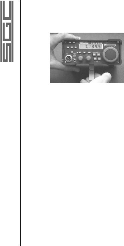
6.1.1 DESK TOP INSTALLATION
A Flip Front Foot is supplied with the radio.
This foot can be flipped up to raise the front of the radio 3 inches above the desk level. Additional front flip feet can be ordered separately, catalog number 05-43.
6.1.2 DESK OR BASE MOUNTING (option 05-42)
To mount the SG-2020 in a secure installation, use the optional mounting plate in the transverse or longitudinal position as described below:
A. Remove 3 screws in the bottom of the chassis.
B. Line up the mounting plate so the 3 holes match the screw holes in the chassis.
C. Re-install the 3 pan head screws provided with the plate to secure the radio to the mounting plate.
D. Secure the radio to a flat surface using four self-tapping
|
wood or sheet metal screws. |
|
6.2 MOBILE |
|
6.2.1 POWER CONNECTION |
|
(Negative Ground vehicles only) |
|
The DC power cable for mobile installation should be made with |
|
AWG #12 stranded copper wire. Please review all power supply |
10 |
considerations throughout this manual and apply all recommenda- |
|
|
|
|
© 1998 SGC Inc
SGC Inc. SGC Building, 13737 S.E. 26th St. Bellevue, WA. 98005 USA
P.O.Box 3526, 98009 Fax: 425-746-6384 or 746-7173 Tel: 425- 746-6310 or 1-800-259 7331 E-mail: sgc@sgcworld.com Web site: http://www.sgcworld.com

tions as appropriate. The DC cable should be connected directly to the vehicle battery, rather than to the ignition or accessory circuitry. Route the cable as far away from the ignition wiring and other cables as possible. Keep the length of this cable as short as possible to minimize voltage drop losses.
•Do not plug in the DC power cable to the transceiver until the proper connections are made to the battery; by convention, we recommend a RED cable lead to the POSITIVE battery terminal, and a BLACK cable lead to the NEGATIVE battery terminal. Do not rely on the vehicle chassis to provide the DC negative return path. Make sure the battery terminal connections are tight and remember to check them periodically to assure they remain tight and corrosion free.
•Measure the voltage across the battery terminal with the engine running fast enough to show a charge. This voltage cannot exceed 18 Volts DC as that is the maximum allowable DC Voltage for the SG-2020.
•Measure the voltage at the transceiver end of the cable and confirm that the proper voltage and polarity exist for the SG-2020. The center position of the 3 contact connector is POSITIVE while the left contact (facing the rear of the radio) provides the NEGATIVE connection to the radio.
•Insert the DC power cable connector into the mating connector on the rear panel of the SG-2020, connect antenna coax to the ANTENNA connector, and external speaker connection via the 3.5 mm stereo phone jack if desired.
6.2.2 ANTENNA CONNECTION
Please take a moment to review the base station antenna information in the previous section of this manual. An antenna tuner such as the SG-231 or SG-230 is particularly desirable in a mobile installation as short antennas typical of mobile installations usually provide a hostile load impedance to any HF transceiver. Even if the antenna is resonant near the operating frequency, the bandwidth of such antennas is extremely narrow limiting operating frequency
agility.
11
SGC Inc. SGC Building, 13737 S.E. 26th St. Bellevue, WA. 98005 USA
P.O.Box 3526, 98009 Fax: 425-746-6384 or 746-7173 Tel: 425- 746-6310 or 1-800-259 7331 E-mail: sgc@sgcworld.com Web site: http://www.sgcworld.com
© 1998 SGC Inc

6.2.3 MOBILE MOUNTING OPTIONS
Velcro mobile mounts (option 05-42) with peel-off adhesive are supplied (to be installed by the operator). When using the velcro mount, we recommend the use of a secure cable, which should be attached between the radio chassis (or mounting plate) and the vehicle for added safety. For a more secure and versatile installation, an optional pedestal mount system is also available from your dealer.
Note: SGC assumes no liability for damage or injury which could occur in the event of an accident or collision.
7.0 SG-2020 APPLICATIONS
7.1.HAM GEAR VOICE
The SG-2020 is a multi-purpose ham radio, ideally suited for base, mobile, or portable use. Because of its unique characteristics, it will out perform many of its more expensive competitors in the market place.
Low current consumption, both in receive and transmit allows this equipment to operate when others will not. In addition, it can be operated by simple “D” size drycell batteries. Its transmit characteristics with 20W output and adequate speech compression, allows “on air” performance to be perceived as a 100W transceiver. The simple but effective settings capability from the RF gain, pass band tuning, and audio frequency band width allows the unit to operate efficiently in any severe communication environment. This, combined with low intermodulation of + 18 dbm and the frequency scanning feature, make this low cost transceiver ideal as a base station monitor.
The SG-2020 HF radio is unique as a portable product on the global market, because its outstanding performance, small size, quality, and multi application capability.
12
© 1998 SGC Inc
SGC Inc. SGC Building, 13737 S.E. 26th St. Bellevue, WA. 98005 USA
P.O.Box 3526, 98009 Fax: 425-746-6384 or 746-7173 Tel: 425- 746-6310 or 1-800-259 7331 E-mail: sgc@sgcworld.com Web site: http://www.sgcworld.com

7.2HAM GEAR CW
In the development of this product, special attention was given to design a product with excellent CW operation. Two key jacks are provided; one for a straight key (mono jack) and the other for an electronic keyer (stereo jack). The straight key allows the operator full break in capability, and also the transmitter can be keyed by using a separate foot switch or depressing the push button on the microphone. The second jack is designed for operation with the internal electronic keyer that preconditions the speed of the keying from 5 to 60 words per minute. The software design is highly sophisticated and has been acclaimed by many hard core CW operators. Power adjustment capability is provided from the front panel; from 25 watts to below 1 watt. Accurate adjustment or reading from the indicator is not supported. At 5 watts the reading may be within plus or minus 1 watt and 15 watts it maybe within plus or minus 2 watts. Higher deviation in some instances may be recorded and the operator can set his own table for the particular radio. Combining the proper use of audio level, RF level, passband tuning, audio frequency and bandwidth tuning, the CW operator will enjoy superb CW communications world wide. From a home base station or to the North Pole or the, Amazon jungle, the SG-2020 functions as a remarkable CW portable unit.
7.3HAM AND COMMERCIAL DATA COMMUNICATION
The SG-2020 is well suited for data communication especially if |
|
operated with modern DSP data modems such as the SG-7200 or |
|
SCS PACTOR. This provides a well balanced combination for |
|
efficient data communication. Most DSP data modems have a 12 |
|
to 20 dB signal to noise ratio advantage over an analog modem; |
|
therefore power output of 1 to 20 watts is more than sufficient to |
|
provide reliable world wide communications. Future developments |
|
of the SG-2020 will be available with external power and frequen- |
|
cy adjustments to allow adjustment of both elements depending on |
|
the signal quality. |
13 |
|
SGC Inc. SGC Building, 13737 S.E. 26th St. Bellevue, WA. 98005 USA
P.O.Box 3526, 98009 Fax: 425-746-6384 or 746-7173 Tel: 425- 746-6310 or 1-800-259 7331 E-mail: sgc@sgcworld.com Web site: http://www.sgcworld.com
© 1998 SGC Inc.

The SG-2020 will switch between receive and transmit in less than 10 milli seconds and is well suited for this type of data operation.
7.4MARINE
The SG-2020 is an ideal marine radio. Since it is not FCC type approved for this operation, it should be used as an auxiliary hobby radio. The low power requirements enable the unit to operate when other equipment on board may not, (i.e. because of a power failure or major accident at sea). In this situation it is perfectly legal to use this radio for emergency transmission. Many marine radio nets exist; the most popular frequency is 14.313 kHz and is run everyday. As an addition to your regular marine electronic equipment, the SG-2020 will give you hours of enjoyment and provide additional safety on your boat. Depending on your cruising area and habits, we recommend you program into the memory channels some popular ship to ship marine frequencies (simplex) and some US Coast Guard high seas frequencies. Appendix A is provided for
popular ham net frequencies and marine frequencies.
7.5AVIATION
The SG-2020 was also designed for aviation operation. It is not FAA type approved for such use, and should be installed on a voluntary basis only. The SG-2020 fits the standard aviation panel width which is under 6 1/4 inches. The units low power current consumption will allow it to work when the rest of the electronic gear in a small airplane may not. It is the perfect companion radio to be operated in a single or double seated airplane from the jungles of Brazil to Indonesia, and from Alaska to the icy Alps.
We recommended programming the preferred frequencies of the operator for fast retrieval. The unit can also be locked so only these channel frequencies are accessible to the operator. This is a practical way to insure that a casual operator calls on the proper frequen-
cy and mode settings.
14
© 1998 SGC Inc
SGC Inc. SGC Building, 13737 S.E. 26th St. Bellevue, WA. 98005 USA
P.O.Box 3526, 98009 Fax: 425-746-6384 or 746-7173 Tel: 425- 746-6310 or 1-800-259 7331 E-mail: sgc@sgcworld.com Web site: http://www.sgcworld.com

7.6COMMERCIAL USE
The SG-2020 is a practical radio for commercial applications, because it can be programmed with only a few necessary channels and then locked. The casual or unfamiliar operator can access only these channels through the main tuning knob. Scanning can be easily accessed allowing perfect channel monitoring of only the channels in use. If only 3 frequencies are required for a normal network; we recommend entering the first operating frequency in the first 8 memory channels 1 thru 8, then the second operating frequency in memory channels 9 thru 13, then the third frequency in memory channels 14 thru 20 and locking the unit. Now when; the operator depresses the MEM push button and rotates the main tuning knob then only the 3 preset channels will be accessible. Scanning will automatically cover only these 3 frequencies.
Note: all memories must be frequency programmed and can not be left empty. Also, the unit is not designed to lock out only a few selective channels.
7.7POWER AMPLIFIER
The SG-2020 is fully compatible with our SG-500 watt amplifier. Expected power from 3 to 18 MHz is not less than 450 watts and not less than 300 watts on the extreme ends of the HF bands.
Only RF is required to control the SG-500. However any suitable linear SSB amplifier can be used with the SG-2020 transceiver.
7.8MONITOR BASE STATION
The special receive and scanning characteristics of the SG-2020 combined with its very low cost allows several transceivers to be used to monitor many different frequencies simultaneously. This provides a flexible and versatile base system. One single, expensive HF radio may not provide the same performance, and its power consumption may be restricted in some applications. The
SG-2020 is the most suited product for this type of application.
15
SGC Inc. SGC Building, 13737 S.E. 26th St. Bellevue, WA. 98005 USA
P.O.Box 3526, 98009 Fax: 425-746-6384 or 746-7173 Tel: 425- 746-6310 or 1-800-259 7331 E-mail: sgc@sgcworld.com Web site: http://www.sgcworld.com
© 1998 SGC Inc
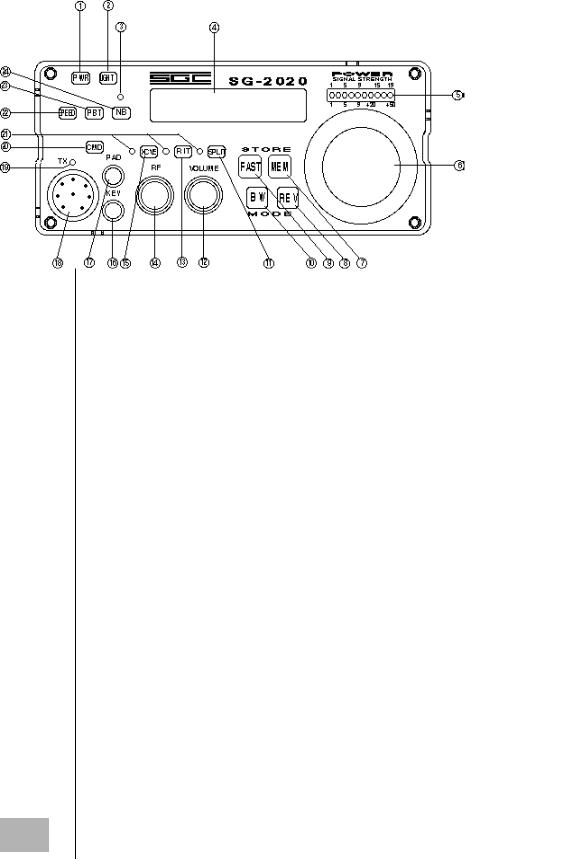
FIGURE 2
KEY |
NAME |
PRIMARY FUNCTION |
1. |
PWR |
Power On / Off. |
2. |
LIGHT |
Backlight On / Off |
3. |
LED |
Noise Blanker Indicator |
4. |
LCD |
Liquid Crystal Display |
5. |
BARGRAPH |
LED Array Display |
6. |
SPINNER |
Main Tuning Control |
7. |
MEM |
Memory Function |
8. |
REV |
Reverse |
9. |
FAST |
Fast Tuning - adjustable rate .1 kHz, .5 kHz, |
|
|
1.0 kHz, or 10 KHz per step |
10. |
"BW" |
Bandwidth (SCAF setting function) |
11. |
SPLIT |
Split Frequency Operation |
12. |
VOLUME |
Audio Frequency Gain Control (receiver) |
13. |
RIT |
RIT / XIT (Receiver / Transmitter Incremental Tuning) |
14. |
RF |
Radio Frequency Gain Control (receiver) |
15. |
"XCVE" |
Transmit and Receive on same Frequency (simplex) |
16. |
KEY |
3.5 mm mono phone jack for CW straight KEY |
17. |
PAD |
3.5 mm stereo phone jack for CW paddles |
18. |
MIC |
Microphone Input Plug; 8P circular |
19. |
LED |
Transmit Active Indicator |
20. |
CMD |
Command; used in conjunction with other buttons |
21. |
LED (3) |
"XCVE", RIT or SPLIT operation Indicators |
22. |
SPEED |
Speed of the built in keyer, adjustable from 5 to 60 WPM |
23. |
"PBT" |
Pass Band Tuning (variable IF passband) |
24. |
NB |
Impulse noise blanker |
16
© 1998 SGC Inc
SGC Inc. SGC Building, 13737 S.E. 26th St. Bellevue, WA. 98005 USA
P.O.Box 3526, 98009 Fax: 425-746-6384 or 746-7173 Tel: 425- 746-6310 or 1-800-259 7331 E-mail: sgc@sgcworld.com Web site: http://www.sgcworld.com
8.0 FRONT PANEL (see figure 2)
The following legend presents the PRIMARY function of each individual control and indicator. Several controls have secondary functions when used in conjunction with the spinner knob or other buttons, as described in the SECONDARY SWITCH FUNCTIONS chapter of this manual.
8.1 CONTROLS |
|
Location of push buttons - (see figure 2) |
|
All four main push buttons: FAST, MEM, BW, REV have been |
|
designed and located for convenient one-hand operation. A few |
|
users have complained that two hands are required and that the |
|
push buttons are too close. Users should become familiar with the |
|
use of one hand, using these push buttons and the main tuning |
|
knob. |
|
8.1.1 PWR |
|
The PWR button turns the radio on and off. When turned on the |
|
display will first show the serial number followed by SGC (SGC |
|
will also be in CW sidetone), and then the DC voltage of the |
|
power supply. Finally, the operating frequency will be displayed |
|
and the transceiver is then ready for operation. |
|
8.1.2 LIGHT |
|
Pressing the LIGHT button turns the display backlight on and off. |
|
Battery life when operating portable can be extended by turning |
|
the backlight off when not needed. |
|
8.1.3 SPEED |
|
This button controls the speed of the internal keyer when operating |
|
in the CW mode. Press and hold the SPEED button. The keyer |
|
speed will be displayed in (WPM) words per minute. To adjust the |
|
keyer to the desired speed, turn the main tuning knob while the |
|
speed button is depressed, and adjust the speed to the desired rate. |
|
The range of adjustments in 1 word increments from 5 WPM to 45 |
|
WPM, and 5 word increments from 45 through 60 WPM. The |
17 |
speed is retained in the SG-2020’s non-volatile memory. |
SGC Inc. SGC Building, 13737 S.E. 26th St. Bellevue, WA. 98005 USA
P.O.Box 3526, 98009 Fax: 425-746-6384 or 746-7173 Tel: 425- 746-6310 or 1-800-259 7331 E-mail: sgc@sgcworld.com Web site: http://www.sgcworld.com
© 1998 SGC Inc

8.1.4 "PBT" (Passband Tuning)
The "PBT" button will activate passband tuning. The display will show the passband offset in KHz. Turn the main tuning knob while pressing the "PBT" button to change the passband tuning as desired.
This will shift the IF passband relative to the BFO frequency. The adjustment rate is from -1000 Hz to +300 Hz in 100 Hz steps.
Shown at left is the effect of the passband tuning. Assume the bandwidth is set at 2.0 KHz. For lower sideband, all adjustments are symmetrical in relation to the upper sideband.
Note:
Accurate calibration is not supported in Passband Tuning
8.1.5 NB (Noise Blanker)
This button controls the noise blanker. The LED above the NB button is lit when the blanker is activated. The noise blanker is designed to provide modest blanking of impulse (ignition) type noise without degrading the performance of the receiver. Normally the blanker would remain in the off condition.
|
8.1.6 "XCVE" / RIT / SPLIT |
|
|
The receiver is general coverage and can be tuned to any |
|
|
frequency between 1.8 MHz and 29.7 MHz. The transmitter will |
|
|
not operate if the frequency is set outside the amateur bands. Inside |
|
18 |
||
|
||
|
|
© 1998 SGC Inc
SGC Inc. SGC Building, 13737 S.E. 26th St. Bellevue, WA. 98005 USA
P.O.Box 3526, 98009 Fax: 425-746-6384 or 746-7173 Tel: 425- 746-6310 or 1-800-259 7331 E-mail: sgc@sgcworld.com Web site: http://www.sgcworld.com

the amateur bands it is the operator's responsibility to transmit only on modes and frequencies consistent with his or her class of license and regional recommended band plan.
In the "XCVE" position the SG-2020 receives and transmits on the same frequency.
Press the RIT(Receiver Incremental Tuning) button and the transmit frequency remains fixed while the receive frequency can be varied. Push the REV button while in RIT and the transmit frequency will be displayed and can be tuned while the receive frequency remains fixed. (XIT-Transmitter Incremental Tuning)
Working Split: (receiving on one frequency while transmitting on a different frequency)
Example: The DX station is listening up band by about 5 kHz.
1.Tune in the DX station while in "XCVE".
2.Press SPLIT.
3.Press and hold the REV button while tuning to listen for other stations calling the DX station upband
(by about 5 KHz).
4.When you have found the DX station's listening frequency, release the REV button and make your call. You will be transmitting on his listening frequency and listening on his transmitting frequency.
5.Remember to switch off the SPLIT when moving for another QSO.
When changing from RIT to "XCVE" the RIT transmit frequency will become the active frequency.
Note: Pressing the SPLIT button also serves to ‘lock’ the receive frequency.
8.1.7 FAST
By pressing the FAST button while turning the main tuning knob, the tuning rate will be set to one of four different values: .1 kHz, .5 kHz, 1.0 kHz, or 10 KHz (see section 9.7). Normal tuning rate is .1 KHz in 10 Hz steps. This feature allows the operator to move to different parts of the band quickly.
19
SGC Inc. SGC Building, 13737 S.E. 26th St. Bellevue, WA. 98005 USA
P.O.Box 3526, 98009 Fax: 425-746-6384 or 746-7173 Tel: 425- 746-6310 or 1-800-259 7331 E-mail: sgc@sgcworld.com Web site: http://www.sgcworld.com
© 1998 SGC Inc.

8.1.8 MEM (Memory)
The SG-2020 has 20 user accessible memories. The unit comes from the factory with the memories preset to a few frequencies in each amateur band for convenience. However, these preselected frequencies may be changed by the operator at any time desired. Press the MEM button and turn the main tuning knob to step from one stored frequency to another. Tune to a new frequency using the FAST button if the new frequency is some distance from the previous one. Press the FAST button and hold while pressing the MEM button. The new frequency is now stored in the current memory.
It is possible to toggle between two frequencies through use of the MEM button. For example, suppose you want to check a net frequency periodically while operating elsewhere on the band. Press the MEM button and the frequency will change to the current memory frequency. Tune to a new frequency. If you press it once more you will return to the last used frequency. Each time you press MEM you will alternate between the current memory and the frequency last used.
The following frequencies have been preset as defaults into the memory locations at the factory:
Memory |
Frequency |
Memory |
Frequency |
1 |
1850 KHz |
11 |
14150 KHz |
2 |
1950 KHz |
12 |
14300 KHz |
3 |
3700 KHz |
13 |
18100 KHz |
4 |
3900 KHz |
14 |
18150 KHz |
5 |
7040 KHz |
15 |
21050 KHz |
6 |
7140 KHz |
16 |
21350 KHz |
7 |
7230 KHz |
17 |
24900 KHz |
8 |
10105 KHz |
18 |
24950 KHz |
9 |
10125 KHz |
19 |
28200 KHz |
10 |
14050 KHz |
20 |
28450 KHz |
Note: Each memory retains the following parameters: receive frequency, transmit frequency, mode (USB/LSB/CW), XCVE/RIT/SPLIT, bandwidth setting, and transmitter output power. Memories can be retuned to the factory presets by pressing MEM button while turning the power on. Channel numbers are not
assigned, and therefore are not displayed.
20
© 1998 SGC Inc
SGC Inc. SGC Building, 13737 S.E. 26th St. Bellevue, WA. 98005 USA
P.O.Box 3526, 98009 Fax: 425-746-6384 or 746-7173 Tel: 425- 746-6310 or 1-800-259 7331 E-mail: sgc@sgcworld.com Web site: http://www.sgcworld.com

8.1.9 "BW" (Bandwidth)
Press the "BW" button. The display will show the receiver bandwidth. Turn the main tuning control while pressing the "BW" button to change bandwidth. It is adjustable from 2.7 KHz to 100 Hz in 100 Hz steps.
8.1.10 MODE SELECTION ("BW" + REV)
To display the current operating mode (USB / LSB / CW), press "BW". To select another mode, hold "BW" and momentarily press REV until desired mode appears on the display. Release "BW" to return to frequency display.
8.1.11 RF GAIN
The RF knob controls the RF gain of the receiver. When receiving extremely strong stations, it may be desirable to reduce the receiver’s RF gain by adjusting this control in the counter clockwise direction. Normal position for this control is in its maximum or fully clockwise position.
8.1.12 VOLUME
The VOLUME knob controls the AF gain of the receiver. Maximum receive audio is when this control is in its fully clockwise position.
9.0SECONDARY SWITCH FUNCTIONS
9.1BARGRAPH MODE (CMD + LIGHT)
When pressing CMD and LIGHT simultaneously, the bargraph display toggles between 'full' bar display and 'peak' bar display.
9.2 DC INPUT VOLTMETER (CMD + SPEED) |
|
|
When pressing and holding CMD and SPEED simultaneously, |
but |
|
momentarily, the LCD will display DC Input Voltage. The voltage |
||
will be displayed until one of the following actions is performed: |
||
a. move the tuning knob. |
|
|
b. Initiate transmit while in CW mode. |
|
|
|
21 |
|
c. depress any of the following keys: |
|
|
|
|
|
SGC Inc. SGC Building, 13737 S.E. 26th St. Bellevue, WA. 98005 USA
P.O.Box 3526, 98009 Fax: 425-746-6384 or 746-7173 Tel: 425- 746-6310 or 1-800-259 7331 E-mail: sgc@sgcworld.com Web site: http://www.sgcworld.com
© 1998 SGC Inc

1.any ‘CMD’ + ‘XXX’ combination
2.‘SPEED’
3.‘"PBT"’
4.‘MEM’
5.‘"BW"’
9.3Tx OUTPUT POWER LEVEL ADJUST (CMD + NB)
When pressing CMD and NB simultaneously, but momentarily, Tx output power level is adjustable by rotating the main tuning knob. Adjustment levels are made in increments of approximately one watt, from 0 to 20 watts. To return to the frequency display, press MEM. To enter this setting in the last recalled memory, press FAST + MEM. Accurate calibration is not supported.
|
9.4 |
MEMORY SCAN (CMD + MEM) |
||
|
To initiate memory scan mode, press CMD and MEM simultane- |
|||
|
ously, but momentarily. The SG-2020 will begin scanning the 20 |
|||
|
memories. To stop memory scan, press any button or transmit. |
|||
|
9.5 FREQUENCY SCAN (CMD + "PBT") |
|||
|
To initiate frequency scan mode, first tune to the desired starting |
|||
|
frequency using the main tuning control. Pressing CMD and |
|||
|
"PBT" simultaneously begins the frequency scan. Blinking LED’s |
|||
|
will indicate the direction of the scan. To reverse the scan direc- |
|||
|
tion, press REV momentarily. To stop frequency scan, rock the |
|||
|
tuning knob back and forth. |
|||
|
9.6 |
ADJUST FREQUENCY SCAN VARIABLES (CMD + REV) |
||
|
The following scan variables may be adjusted by the user by |
|||
|
pressing CMD and REV simultaneously but momentarily: |
|||
|
DWELL TIME: 0.1 thru 10 seconds, 0.1 second increments |
|||
|
Dwell: ‘d’ is displayed (Press MEM to enter). |
|||
|
PAUSE on DETECTION: 1 thru 120 seconds,1 second increment. |
|||
|
Pause: ‘P’ is displayed (Press MEM to enter). |
|||
|
DETECTION THRESHOLD: |
S1 thru S9, 1 'S' unit increment . |
||
|
Threshold: ‘S’ is displayed |
(Press MEM to enter). |
||
22 |
||||
AUDIO BLANKING TIME: 0 - 1.28 seconds in 10 ms intervals |
||||
|
|
|
|
|
© 1998 SGC Inc
SGC Inc. SGC Building, 13737 S.E. 26th St. Bellevue, WA. 98005 USA
P.O.Box 3526, 98009 Fax: 425-746-6384 or 746-7173 Tel: 425- 746-6310 or 1-800-259 7331 E-mail: sgc@sgcworld.com Web site: http://www.sgcworld.com

Blanking: ‘b’ is displayed (Press MEM to enter).
FREQUENCY STEP: .1, .5, 1.0, or 2.5 kHz.
FREQ Step: ‘F’ is displayed (Press MEM to enter).
9.7ADJUST ‘FAST’ INCREMENTAL VALUE (CMD + FAST)
While pressing CMD and FAST simultaneously, but momentarily, turn main tuning knob to adjust the incremental value by .1, .5, 1.0, or 10 kHz. To store this value into memory, press MEM.
9.8 CALIBRATE FREQUENCY DISPLAY (CMD + "XCVE")
To calibrate the frequency display, press CMD and "XCVE" simultaneously, but momentarily. All three mode LED’s ("XCVE",RIT,SPLIT) will be on. Adjust by turning the main tuning knob. To store this calibration, press MEM.
Note: If the frequency display has been re-calibrated, the default channel memory frequencies will be offset by the same corrected value. If an adjustment has been made, it may be necessary to reenter the frequency into the 20 memories.
10.0 POWER - ON OPTIONS
10.1 “CMD” BUTTON |
|
Note: Holding the “CMD” button upon power up will cause the |
|
LCD to display “C”. This has no user function and is for factory |
|
use only. The sequence will abort to normal radio operation about a |
|
second after the “CMD” button is released. |
|
10.2 RESTORE FACTORY MEMORY DEFAULTS (MEM) |
|
To restore factory memory defaults, hold MEM upon powering up |
|
of unit. |
|
10.3 BACKLIGHT DEFAULT ON / OFF and LED Test |
|
Power up the radio while depressing the ‘LIGHT’ button. Hold it |
23 |
until either ‘dl ON’ or ‘dl OFF’ is displayed. Select whether you |
SGC Inc. SGC Building, 13737 S.E. 26th St. Bellevue, WA. 98005 USA
P.O.Box 3526, 98009 Fax: 425-746-6384 or 746-7173 Tel: 425- 746-6310 or 1-800-259 7331 E-mail: sgc@sgcworld.com Web site: http://www.sgcworld.com
© 1998 SGC Inc

want the backlight on or off when the radio is turned on. This is done by using the ‘REV’ button to toggle between ‘dl ON’ and ‘dl OFF’. Store the choice by depressing the ‘MEM’ button. Once the ‘MEM’ button is released, a sequential test is performed on each LED and the backlight. The radio then reverts to normal operation.
10.4 LOCKOUT ("PBT" + RIT)
To toggle the lockout function on or off, hold "PBT" and RIT simultaneously upon power up. This command locks out all functions except LIGHT, "BW", MEM (select or scan), NB, and DC VOLT METER. ‘REV’ toggles the choice between ‘on’ and ‘off.’ To store this choice into the memory, press MEM.
10.5 CODE REVISION DISPLAY (REV)
Pressing REV upon power up displays firmware revision.
10.6 MEMORY CHANNEL RECOVERY PROCEDURE
The following procedure will cure the loss of the 20 memory channels, when the display reads 66 MHz at power up .
(A)Power up the radio
(B)Engage "channel scan" mode, by doing the following:
(1)depress and hold "CMD" button
(2)depress "MEM" button
(3)release "MEM" button
(4)release "CMD" button
NOTE: It may take up to 5 minutes to re-establish the memories, although it is usually accomplished in just a few seconds.
(C) Exit "channel scan" by depressing any key.
Warning: This problem can occur
A.If power is removed intermittently.
B.If battery or low DC voltage exist and transmit is operated Please avoid the above conditions.
NOTE: For proper and faster recovery please insure the input voltage is higher than 12 volts DC.
24
© 1998 SGC Inc
SGC Inc. SGC Building, 13737 S.E. 26th St. Bellevue, WA. 98005 USA
P.O.Box 3526, 98009 Fax: 425-746-6384 or 746-7173 Tel: 425- 746-6310 or 1-800-259 7331 E-mail: sgc@sgcworld.com Web site: http://www.sgcworld.com

11.0BARGRAPH DISPLAY
11.1POWER / S-METER
In receive the bargraph shows relative signal strength in S units. In transmit the output power is also displayed. Hold the “REV” button while transmitting and the reflected power will be displayed. The display returns to forward power indication when the “REV” button is released. Remember, that when operating SSB voice transmission the displayed peak reading on the bargraph will be substantially lower than the actual peak output power being transmitted and does not indicate a transmitter fault.
S-METER LEVEL DEFINITIONS
LED |
Approximate Level |
S1 |
Always on |
S2 |
.8µv |
S5 |
3µv |
S7 |
12µv |
S9 |
50µv |
+10 |
150µv |
+30 |
500µv |
+40 |
1.5mv |
+50 |
15mv |
NOTE 1: The above S-Meter levels are approximate, and accurate calibration is not supported.
NOTE 2: The power levels in transmit are approximate, and accurate calibration is not supported. The bargraph will also work in the Iambic key mode.
25
SGC Inc. SGC Building, 13737 S.E. 26th St. Bellevue, WA. 98005 USA
P.O.Box 3526, 98009 Fax: 425-746-6384 or 746-7173 Tel: 425- 746-6310 or 1-800-259 7331 E-mail: sgc@sgcworld.com Web site: http://www.sgcworld.com
© 1998 SGC Inc
 Loading...