

Page 1

InHand VG710 InVehicle Gateway User Manual
InHand VG710 InVehicle Gateway
User Manual
Issue: V1.0 — January, 2020
1
Page 2

Declaration
Thank you for choosing our product. Before using the product, read this manual carefully.
The contents of this manual cannot be copied or reproduced in any form without the written
permission of InHand.
Due to continuous updating, InHand cannot promise that the contents are consistent with the actual
product information, and does not assume any disputes caused by the inconsistency of technical
parameters. The information in this document is subject to change without notice. InHan d reserves the
right of final change and interpretation.
© 2020 InHand Networks. All rights reserved.
Conventions
Symbol Indication
< >
""
>
Cautions
Note Notes contain detailed descriptions and helpful suggestions.
Content in angle brackets “<>” indicates a button name. For example, the <OK>
button.
'''' indicates a window name or menu name. For example, the pop-up window "New
User."
A multi-level menu is separated by the double brackets ">". For example, the
multi-level menu File > New > Folder indicates the menu item [Folder] under the
sub-menu [New], which is under the menu [File].
Means reader be careful. Improper action may r esult in loss of data or device
damage.
Contact Us
Add: 3900 Jermantown Rd., Suite 150, Fairfax, VA 22030 USA
E-mail: [email protected]
T: +1 (703) 348-2988
www.inhandnetworks.com
URL:
i
Page 3

InHand VG710 InVehicle Gateway User Manual
Contents
1 Overview ............................................................................................................................................. 1
2 Hardware ............................................................................................................................................ 2
2.1 Indicator Description ................................................................................................................. 2
2.2 Restoring Default Settings via the Reset Button ....................................................................... 3
3 Default Settings ................................................................................................................................... 4
4 Login and Network Access ................................................................................................................ 6
4.1 Network Access via the Dialup Card ........................................................................................ 6
4.2 Network Access via Wi-Fi ........................................................................................................ 9
5 Network Management ...................................................................................................................... 11
5.1 Network ................................................................................................................................... 11
5.1.1 Bridge Port ................................................................................................................ 11
5.1.2 VLAN Port ................................................................................................................... 12
5.1.3 ADSL Dialup (PPPoE) ................................................................................................. 13
5.1.4 Wi-Fi ............................................................................................................................ 13
5.1.5 Loopback Port .............................................................................................................. 15
5.1.6 Layer 2 Switch .............................................................................................................. 15
5.2 OBD ........................................................................................................................................ 16
5.3 VPN Application ..................................................................................................................... 18
5.3.1 IPsec ............................................................................................................................. 18
5.3.2 GRE .............................................................................................................................. 22
5.3.3 L2TP ............................................................................................................................. 23
5.3.4 OpenVPN ..................................................................................................................... 25
5.3.5 Certificate Management ............................................................................................... 26
5.4 Services ................................................................................................................................... 28
5.4.1 DHCP (Automatic IP Address Allocation) .................................................................. 28
5.4.2 DNS .............................................................................................................................. 29
5.4.3 DDNS ........................................................................................................................... 30
I
Page 4

InHand VG710 InVehicle Gateway User Manual
5.4.4 SMS .............................................................................................................................. 32
5.4.5 GPS ............................................................................................................................... 33
5.4.6 QoS ............................................................................................................................... 35
5.4.7 Traffic Control .............................................................................................................. 36
5.5 Firewall .................................................................................................................................... 37
5.5.1 ACL .............................................................................................................................. 37
5.5.2 NAT .............................................................................................................................. 38
5.5.3 MAC-IP Binding .......................................................................................................... 39
5.6 Routing .................................................................................................................................... 40
5.6.1 Static Routing ............................................................................................................... 40
5.6.2 Dynamic Routing ......................................................................................................... 40
5.7 Link Backup ............................................................................................................................ 45
5.7.1 SLA .............................................................................................................................. 45
5.7.2 Track ............................................................................................................................. 46
5.7.3 VRRP............................................................................................................................ 47
5.7.4 Interface Backup ........................................................................................................... 49
5.8 Wizards .................................................................................................................................... 51
5.8.1 New Cellular ................................................................................................................. 51
5.8.2 New IPsec Tunnel ........................................................................................................ 52
5.8.3 IPsec Experts' Configuration ........................................................................................ 53
5.8.4 New L2TPv2 Tunnel .................................................................................................... 53
5.8.5 New Port Mapping ....................................................................................................... 54
6 APP Management ............................................................................................................................. 56
7 Connecting the Gateway to a Cloud Platform ............................................................................... 57
8 Industrial Ports (Serial Ports) ......................................................................................................... 58
8.1 DTU ......................................................................................................................................... 58
8.2 IO Ports ................................................................................................................................... 60
9 System Management ........................................................................................................................ 61
II
Page 5

InHand VG710 InVehicle Gateway User Manual
9.1 System ..................................................................................................................................... 61
9.2 System Time ............................................................................................................................ 61
9.3 Management Services .............................................................................................................. 63
9.4 User Management .................................................................................................................... 64
9.5 AAA ........................................................................................................................................ 64
9.5.1 Radius ........................................................................................................................... 65
9.5.2 Tacacs+ ......................................................................................................................... 66
9.5.3 LDAP............................................................................................................................ 66
9.5.4 AAA Authentication ..................................................................................................... 67
9.6 Configuration Management ..................................................................................................... 68
9.7 SNMP ...................................................................................................................................... 69
9.7.1 SNMP ........................................................................................................................... 69
9.7.2 SnmpTrap (Alarm) ....................................................................................................... 70
9.7.3 SnmpMibs .................................................................................................................... 71
9.8 Alarm ....................................................................................................................................... 72
9.9 System Logs ............................................................................................................................ 73
9.10 System Upgrade .................................................................................................................... 74
9.11 System Reboot ....................................................................................................................... 75
10 Diagnostic Tools .............................................................................................................................. 76
III
Page 6
InHand VG710 InVehicle Gateway User Manual
1 Overview
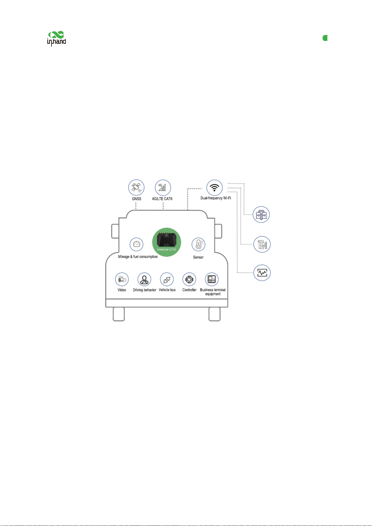
InHand VG710 is a new-generation 4G in-vehicle gateway oriented at the Internet of Vehicles (IoV).
It provides fast and safe networks for automobiles and transport service vehicles, meeting the
requirements of police vehicles, emergen cy command v ehicles, eng ineering vehicles, medic al vehicles,
and logistics vehicles for fast mobile networks. It is used with a cloud-based remote veh icle
management platform to provide ubiquitous accessible networks and uninterrupted operation
supervision for logistics management, asset tracking, mobile office, and government security.
Fig. 1 Application case
1
Page 7

InHand VG710 InVehicle Gateway User Manual
Blinking green --- An AP is associated.
2 Hardware
2.1 Indicator Description
VG710 Indicator Status and Definition
Steady off --- The device is powered off.
Steady red --- The system is starting.
System
Cellular
Signal
GNSS
Blinking green --- The system operates properly.
Blinking red --- The system is faulty.
Blinking blue --- The system is being upgraded.
Steady off --- The dialup function is disabled.
Blinking green --- Dialup is in progress.
Steady green --- Dialup succeeds.
Blinking red --- Dialup fails (no module or SIM card is detected).
Steady off --- The current dialup card has no signal.
Steady red --- The current dialup card has weak signals (signal strength: ≤ 9 asu).
Steady blue --- The current dialup ca rd has moderate signals (signal strength: 10–19
asu).
Steady off --- GNSS is disabled.
Blinking green --- Positioning is in progress.
Steady green --- Positioning is completed.
Used as an AP:
Wi-Fi 2.4G
Steady off --- The AP is disabled.
Blinking green --- The AP operates properly.
Used as a STA:
Steady off --- The STA is disabled, or no AP is associated.
Steady green --- Connection fails due to a wrong password after an AP is associated.
2
Page 8
InHand VG710 InVehicle Gateway User Manual
Used as an AP:
Steady off --- The AP is disabled.
Blinking blue --- The AP operates properly.
Wi-Fi 5G
U1 and U2
Used as a STA:
Steady off --- The STA is disabled, or no AP is associated.
Steady blue --- Connection fails due to a wrong password after an AP is associated.
Blinking blue --- An AP is associated.
U1:
Steady off --- The APP is disabled.
Steady green --- The APP is enabled.
U2:
Steady off --- The virtual private network (VPN) is disabled or abnormal.
Steady green --- The VPN operates properly.
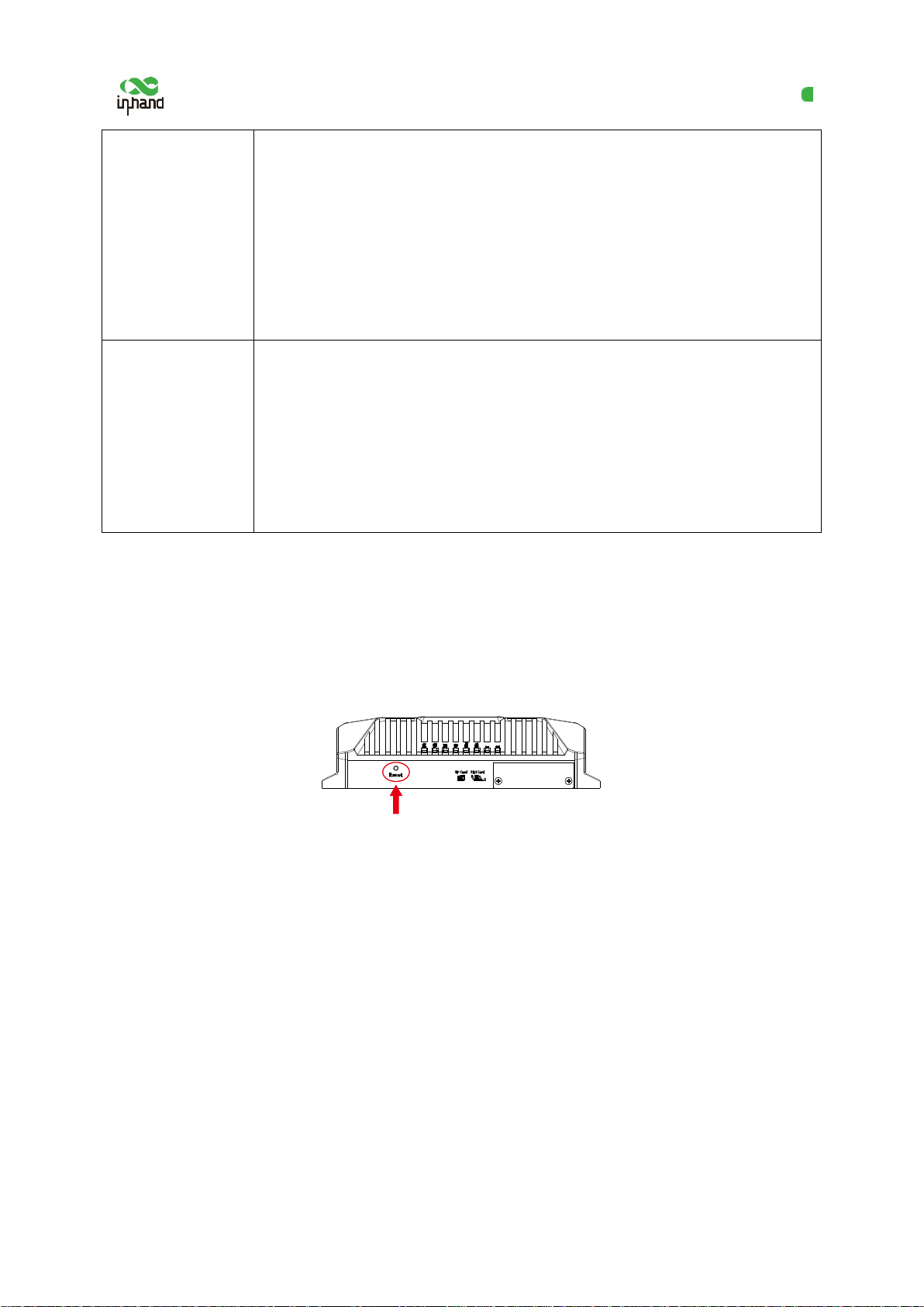
2.2 Restoring Default Settings via the Reset Button
To restore default settings via the Reset button, perform the following steps:
1. Power on the device and immediately press and hold the Reset button. After about 15s, only
the System indicator is steady red.
2. When the System indicator turns off and becomes red again, immediately release th e R eset
button.
3. When the System indicator turns off, press the Reset button (ensure that it blinks red twice)
and then release it. The device is restored to the default settings.
3
Page 9

InHand VG710 InVehicle Gateway User Manual
Dialup over the
is steady green after dialup
SIM function is disabled, and SIM1 is
positioning and
192.168.2.100, and IP addresses can be automatically allocated to
Network access
control for the
HTTP and HTTPS are enabled, with the port numbers of 80 and
3 Default Settings
No. Function Default Settings
− Enabled (The Cellular indicator
succeeds.)
1
cellular network
By default, the dualenabled.
Satellite
2
inertial navigation
service
On-board
3
diagnostics (OBD)
Default settings of
4
Wi-Fi
− Enabled (The GNSS indicator is steady green after positioning
succeeds.)
− The inertial navigation function is enabled.
− Enabled
− The CANbus baud rate is automatically detected.
− The OBD protocol is automatically detected .
− OBD data is automatically scanned.
− The Wi-Fi 2.4G AP is enabled. The SSID starts with VG710-,
followed by six digits.
− The Wi-Fi 5G AP is enabled. The SSID starts with VG71 0-5G-,
followed by six digits.
− WPA2-PSK is used for authentication.
− The password contains the last eight dig its of the SN.
− Four LAN ports are enabled.
− The IP address is 192.168.2.1.
Default settings of
5
Ethernet
6
gateway
− The subnet mask is 255.255.255.0.
− The DHCP server is enabled. The IP address pool is 192.168.2.2–
downstream devices.
−
443 respectively.
4
Page 10

InHand VG710 InVehicle Gateway User Manual
voltage 105: The threshold voltage for resuming
Four digital output channels generate output at low level by
− Telnet is disabled.
− SSH is disabled.
− Access from the cellular network is allowed only over HTTPS.
User name and
7
− adm/123456 (super administrator)
password
− shutdown-delay 30: The power-off delay is 30s.
− standby-mode 1: The power-off function is enabled.
− standby-check-interval 20 indicates the power check interval in
Power
8
standby mode.
management
− standby-voltage 90: The standby threshold voltage is 9 V.
− standby-resume-
9 IO
10 Serial port
normal operating in standby mode is 10.5 V.
−
default, and the pull-up resistor is disabled.
− The pull-up resistor for six digital input channels is disabled.
− RS232
Baud rate: 9600
Data bits: 8 bits
Parity bit: none
Stop bit: 1 bit
− RS485
Baud rate: 9600
Data bits: 8 bits
Parity bit: none
Stop bit: 1 bit
5
Page 11
InHand VG710 InVehicle Gateway User Manual
Power
Cellular antenna
Insert the SIM card
GNSS antenna
4 Login and Network Access
4.1 Network Access via the Dialup Card
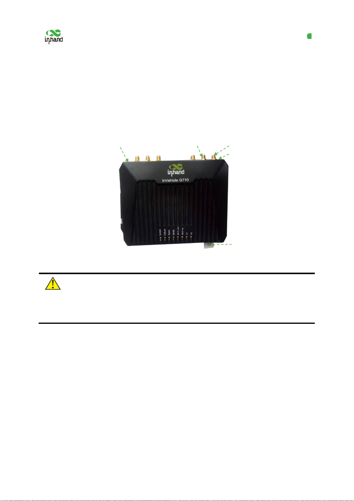
1. Insert the SIM card, connect the GNSS and cellular antennas, and connect the p ower supply and
PC. Insert the diversity dialup antenna when the dialup card has poor signals.
Connect the PC
Note:
Before inserting or removing the SIM card, unplug the power cable; otherwise, the operation will
cause data loss or damage the gateway.
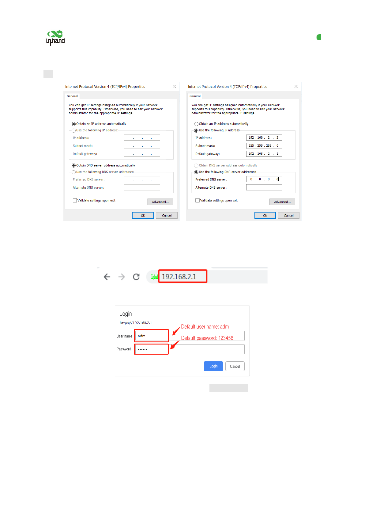
2. Assign an IP address to the PC, which is on the same network segment as the IP address of the
gateway.
Method 1: Enable the PC to obtain an IP address automatically (recommended).
Method 2: Configure a fixed IP address on the same network segment as the gateway address for the
PC.
Step: Select "Use the following IP address", enter any IP address in the range of 192.168.2.2 to
192.168.2.254 (different from the initial IP address 192.168.2.1 of the gateway), the subnet mask
6
Page 12
InHand VG710 InVehicle Gateway User Manual
255.255.255.0, the default gateway address 192.168.2.1, and enter DNS server address, and then click
OK.
Obtain an IP address automatically Use a fixed IP address
3. Open the browser, enter the default IP address 192.168.2.1 of the gateway in the address bar, and
press Enter.
4. Log in (if a blocking prompt is displayed, click "Advanced >> Continue").
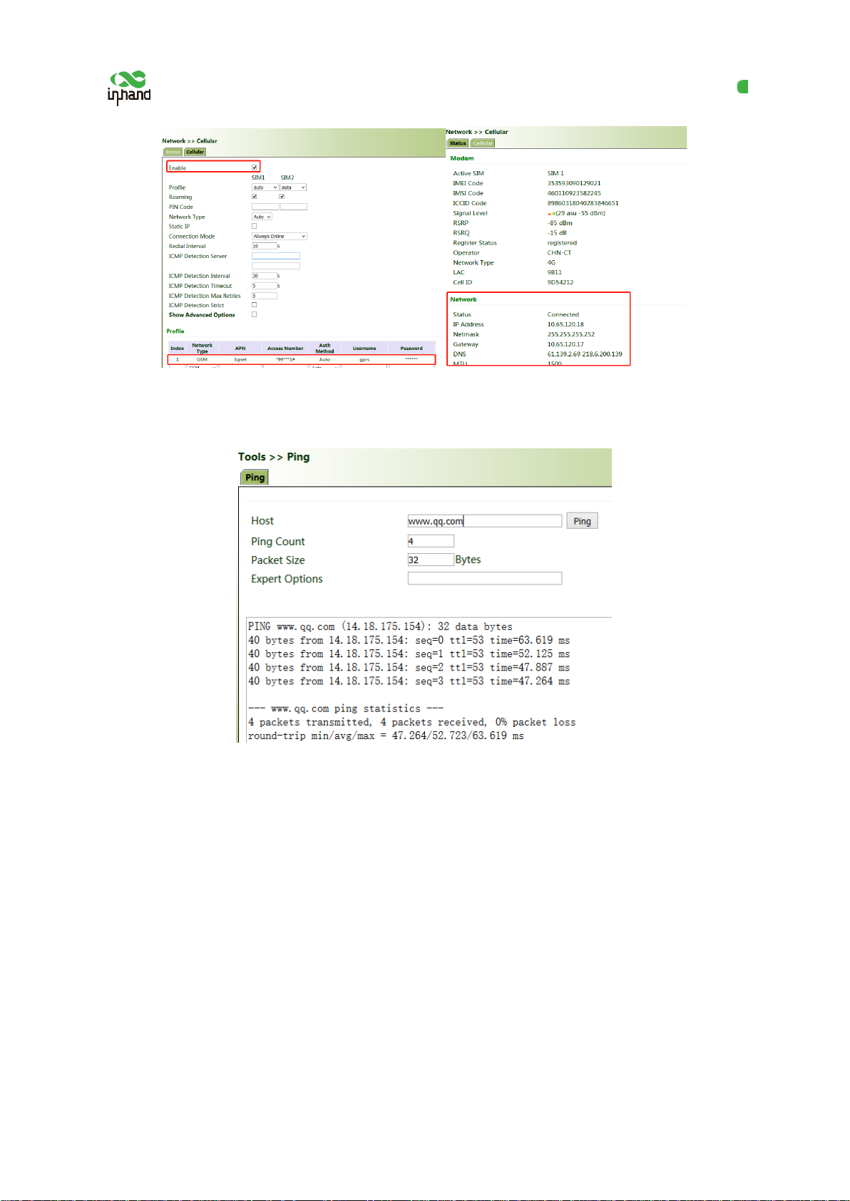
5. Click "Network >> Cellular", check "Enable", and click Apply & Save. If the network connection
status is "Connected" and an IP address has been allocated, the SIM card has been connected to
the network.
(Set the APN parameters for a private-network card.)
7
Page 13
InHand VG710 InVehicle Gateway User Manual
6. Ping a common website in China with a ping detection tool. If there is data transmission, the
device has been successfully connected to the network.
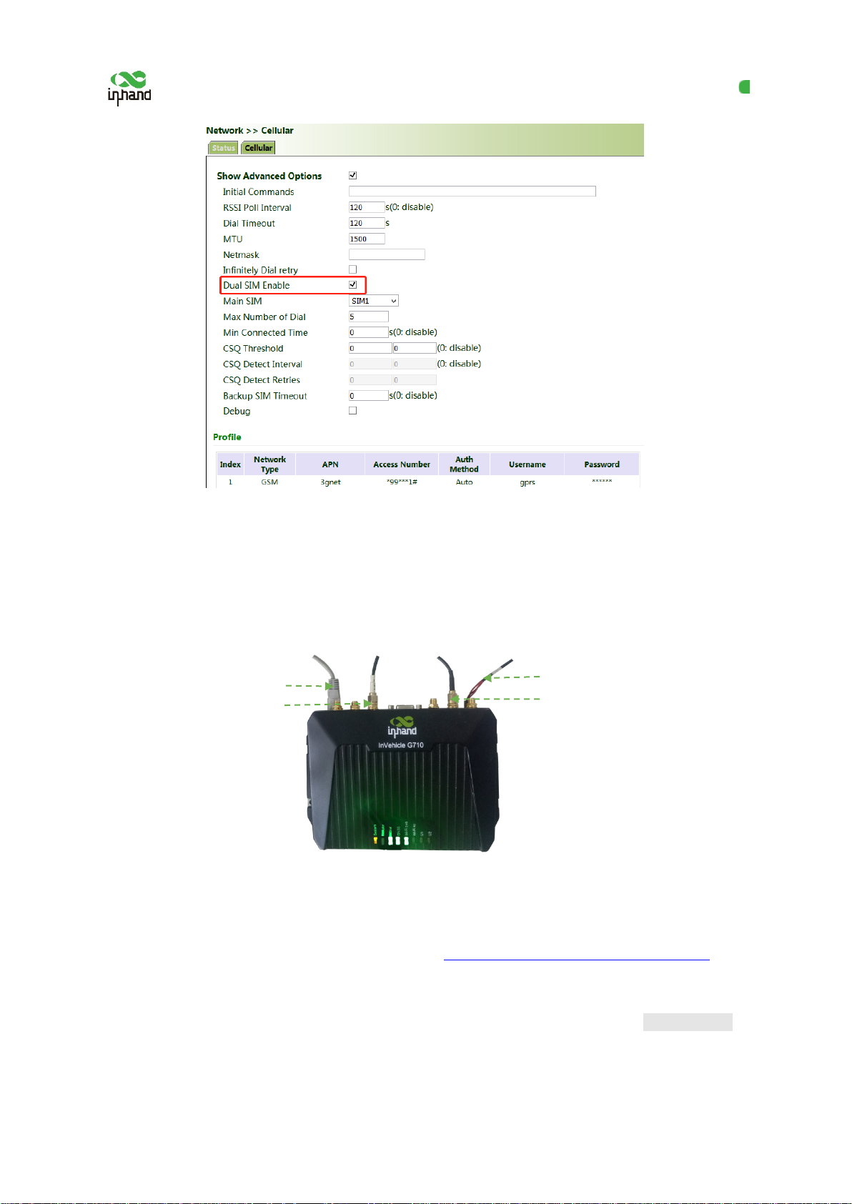
7. Enable the dual-SIM function when two SIM cards are used.
8
Page 14
InHand VG710 InVehicle Gateway User Manual
Power supply
Wi-Fi antenna
GNSS antenna
4.2 Network Access via Wi-Fi
1. Complete the connection shown in the following figure.
Connect the PC
2. Assign an IP address to the PC, which i s on the same network segment as the IP address of the
gateway. Log in to the web page. For details, see 4.1 Network Access via the Dialup Card
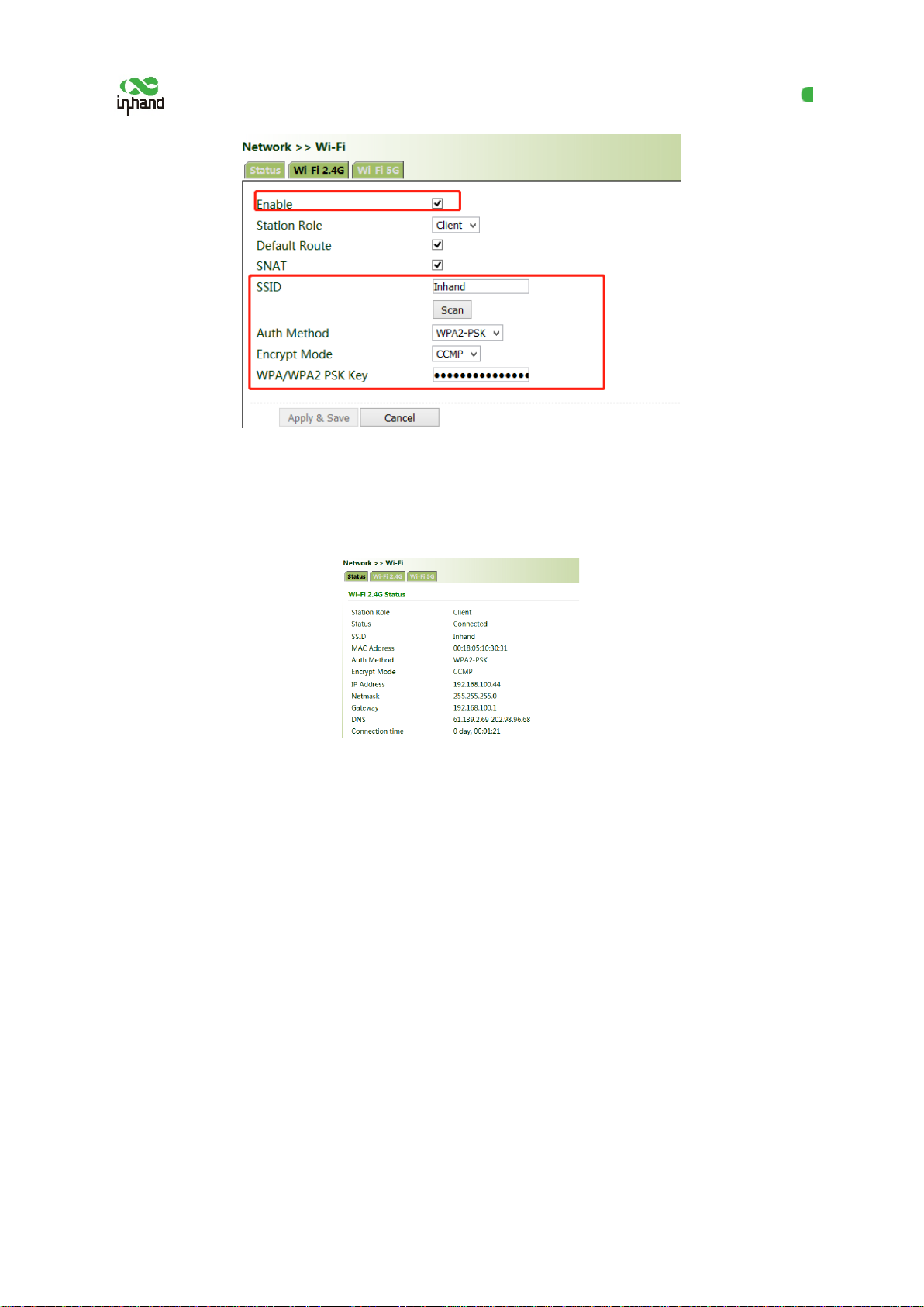
3. Click " Network >> Wi-Fi" and select Wi-Fi 2 .4G or Wi-Fi 5G as a client. Enter the name,
authentication method, and key of an av ailable wireless access point (AP). Click Apply & Save.
9
.
Page 15
InHand VG710 InVehicle Gateway User Manual
4. Click "Status". The current network status is "Connected", and an IP address is obtained
successfully, indicating that the device has been successfully connected to the network via Wi-Fi.
10
Page 16
InHand VG710 InVehicle Gateway User Manual
5 Network Management
In parameter settings, a green text box in dicates a mandatory item, and a pure white tex t
box indicates an optional item.
5.1 Network
5.1.1Bridge Port
A bridge port is intended to connect two different physical LANs over a bridge, to enable storage and
forwarding across LANs at the link layer.
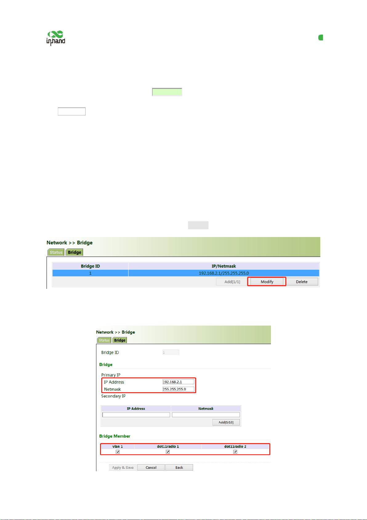
Method for modifying the IP address of a bridge port and bridge members:
1. Click "Network >> Bridge" and select "Bridge >> Modify".
2. Modify the IP address of the bridge port or bridge members. Among the bridge members,
dot11radio1 and dot11radio2 are Wi-Fi 2.4G and Wi-Fi 5G ports respectively.
11
Page 17
InHand VG710 InVehicle Gateway User Manual
5.1.2 VLAN Port
A virtual LAN (VLAN) comprises a group of logical devices and users. These devices an d users are
not limited by physical locations, but can be organized based on functions, departments, applications,
and other factors. They communicate with each other as if they are on the same network segment,
which contributes to the name of VLAN.
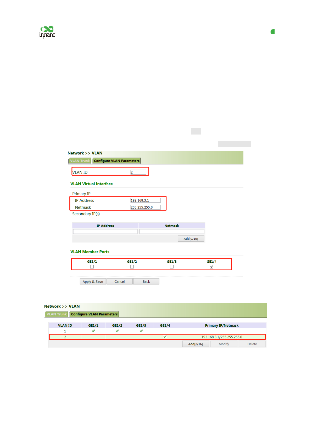
Method for adding a port of VLAN 2:
1. Click "Network >> VLAN >> Configure VLAN Parameters >> Add". Set the virtual IP address of
the port of VLAN 2 and select the member po r t of VLAN 2 as required. Click Apply & Save.
2. Return to the VLAN list. The port of VLAN 2 has been successfully added.
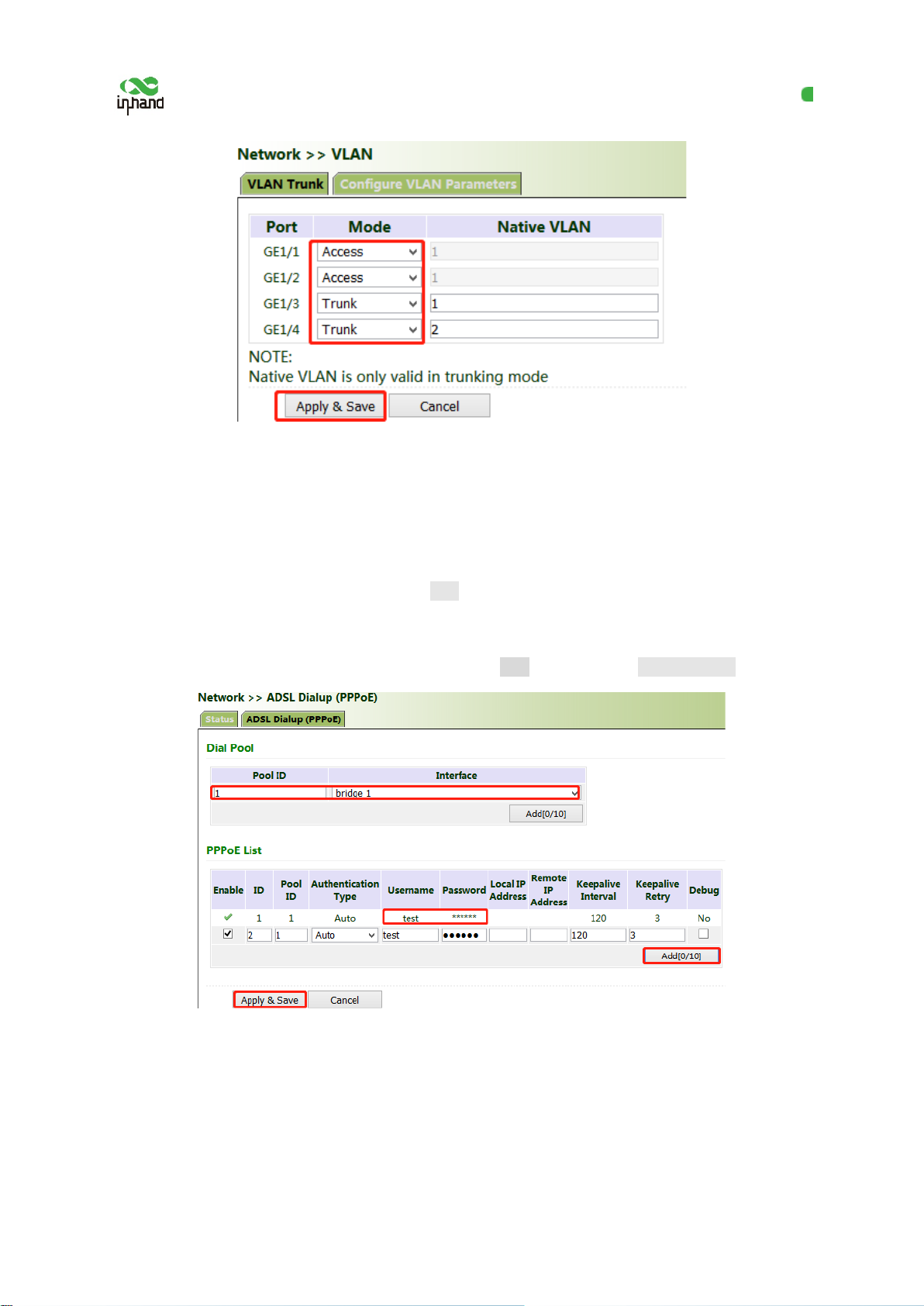
Currently, VLAN ports of the device support two link types: access and trunk. An access port belongs
to only one VLAN and is generally connected to a computer. A trunk port can be used for multiple
VLANs and can receive messages from or send messages to multiple VLANs. It can be connected to a
switch or a user's computer. You can select the link type as required on the "VLAN Trunk" page.
12
Page 18
InHand VG710 InVehicle Gateway User Manual
5.1.3 ADSL Dialup (PPPoE)
Method for connecting the gateway to the PPPoE server:
1. Click "Network > > ADSL Dialup (PPPoE)", select the VG710 interface for connecti ng to the
PPPoE server in the "Dial Pool" bar, and click Add.
2. Enter the user name, password, and pool ID of the PPPoE server in the "PPPoE List" bar. The pool
ID must be the same as that in the "Dial Pool" bar. Click Add, and then click Apply & Save.
5.1.4 Wi-Fi
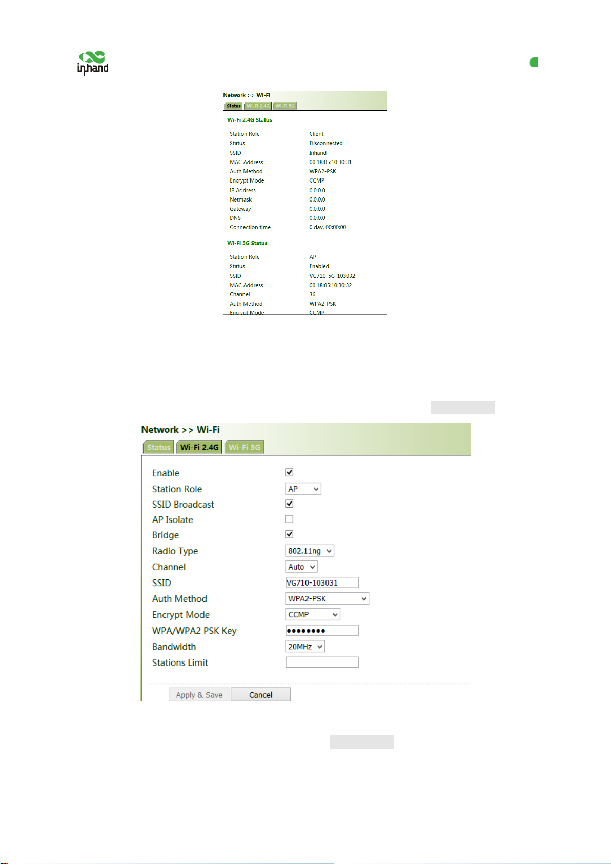
The gateway can be used as an AP or a client. Wh en it is used as an AP, other users can access the
Internet through the gateway via Wi-Fi. When it is used as a client, the gateway connect s to an AP for
Internet access. The status bar shows the current Wi-Fi connection status of the gateway .
13
Page 19
InHand VG710 InVehicle Gateway User Manual
Method for providing network access services for wireless terminals when t he gateway is used as
an AP:
Click "Wi-Fi >> Wi-Fi 2.4 or Wi-Fi 5G" and select "AP" for "Station Role". Enter the SSID,
authentication method, and key consistent with those of the wireless AP. Click Apply & Save.
Method for connecting to an AP for Internet acc ess when VG710 is used as a client:
Select "Client", enter the Wi-Fi SSID and key, and click Apply & Save.
14
Page 20
InHand VG710 InVehicle Gateway User Manual
5.1.5 Loopback Port
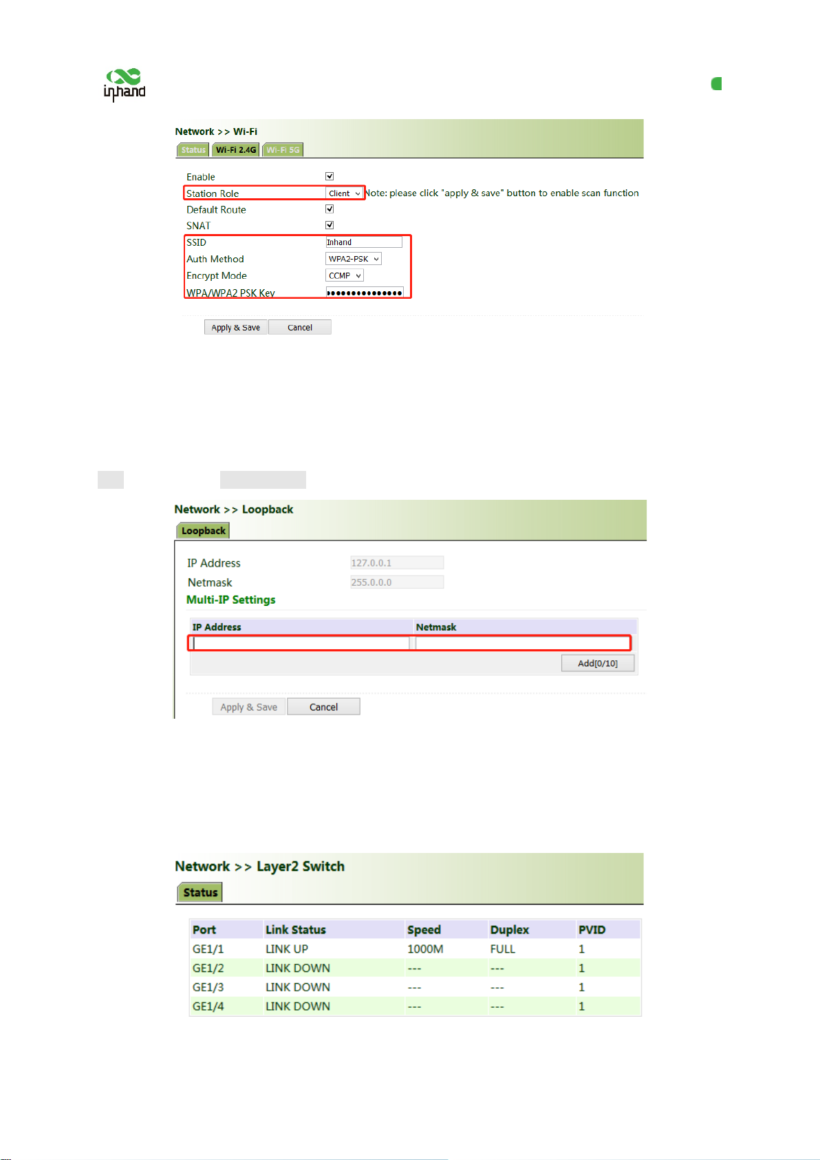
Method for adding Multi-IP Settings:
Click "Network >> Loopback >> Multi-IP Set tings", configure any IP address for the gateway, click
Add, and then click Apply & Save.
5.1.6 Layer 2 Switch
Check the network connection status of GE 1 to GE 4. LINK UP indicates that the network is
connected. LINK DOWN indicates that the network is disconnected.
15
Page 21

InHand VG710 InVehicle Gateway User Manual
5.2 OBD
OBD is used to collect vehicle condition data, obtain emission information, and perform fault
diagnosis in real time. Vehicle condition data includes key parameters such as th e f uel level, mileage,
driving speed, engine speed, engine load, coolant temperature, and brake pressure. Emission
information includes the volume of AdBlue, the operating and monitoring status of various exhaust
post-processing sensors (such as the exhaust gas sensor and diesel particle filter) and catalysts, etc. In
fault diagnosis, standard fault codes of vehicles and description information can be obtained in real
time, so that vehicle maintenance personnel can learn the vehicle health status in time and locate the
faults.
To collect vehicle data, the gateway is connected to the diagnostic port of the vehicle through the I/O
port of the gateway over the OBD-II or J19 39 cable. The cable accessories can be selected or
customized during purchasing. For details about the access method, see Section 4.4 in the VG710
Quick Start Guide. After the gateway starts, the OBD service is automatically enab led to collect key
vehicle condition data and fault code information.
Note:
The power supply and OBD cable of the gateway shall be installed when the vehicle is off.
The vehicle status information is displayed on the OBD status page.
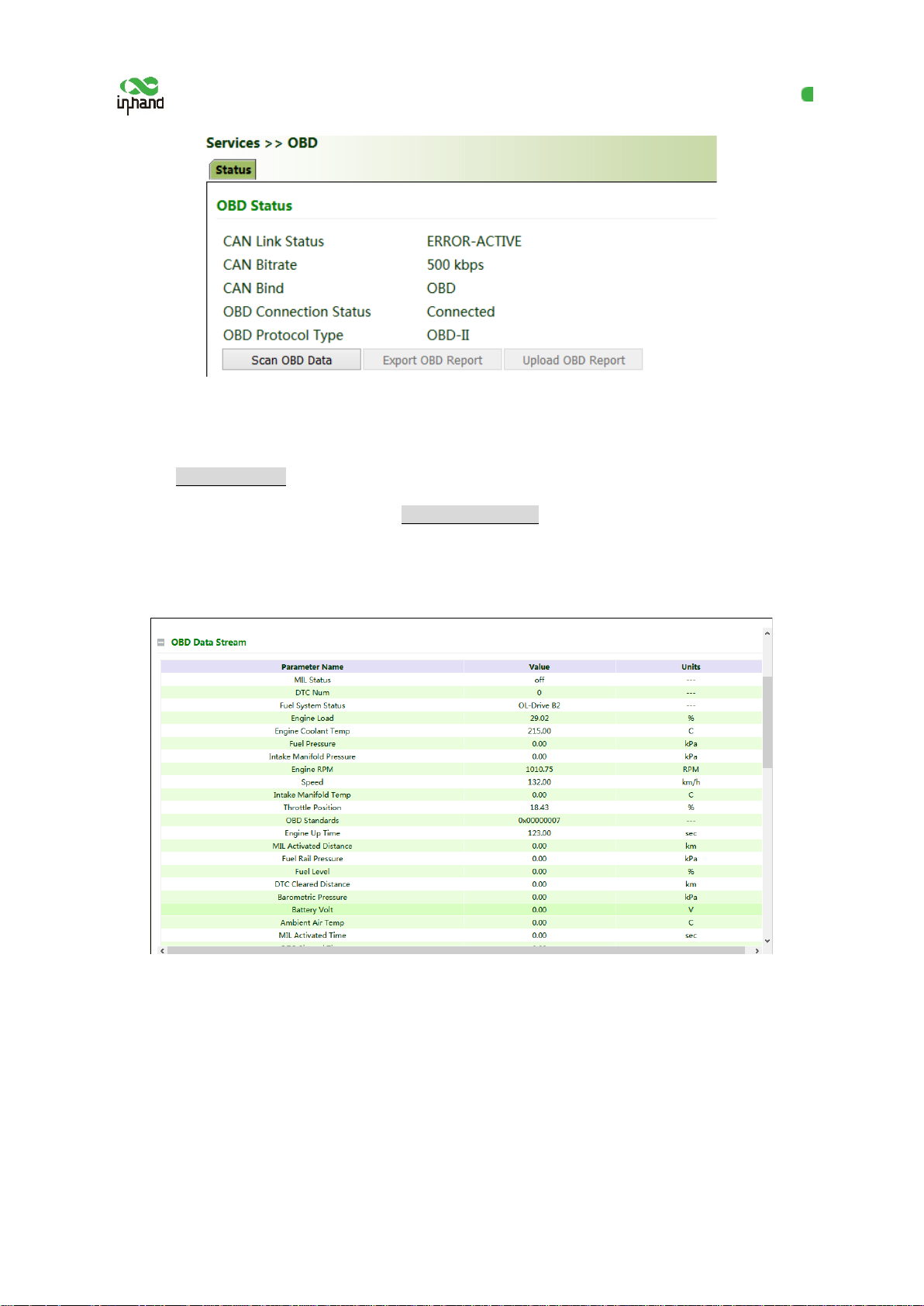
OBD Status:
CAN Link Status (ERROR-ACTIVE indicates that the gateway has successfully connected to the
diagnostic port of the vehicle. Other status indicates that the connection is abnormal or the diagnostic
port of the vehicle is not identified.)
CAN Bitrate (In OBD, the CAN bitrate is automatically adapted, generally 250 kbps or 500 kbps.)
CAN Bind ("OBD" (default) or "Custom")
OBD Connection Status ("Disconnected", "Connecting", or "Connected")
OBD Protocol Type (OBD-II or J1939)
16
Page 22
InHand VG710 InVehicle Gateway User Manual
Scan OBD Data and Export OBD Report:
Click the Scan OBD Data button to generate a OBD data report containing detailed vehicle condition
data and diagnostic information. Click the Export OBD Report button to save the generated OBD data
report to the local storage.
OBD Data Stream: The real-time vehicle condition data is displayed.
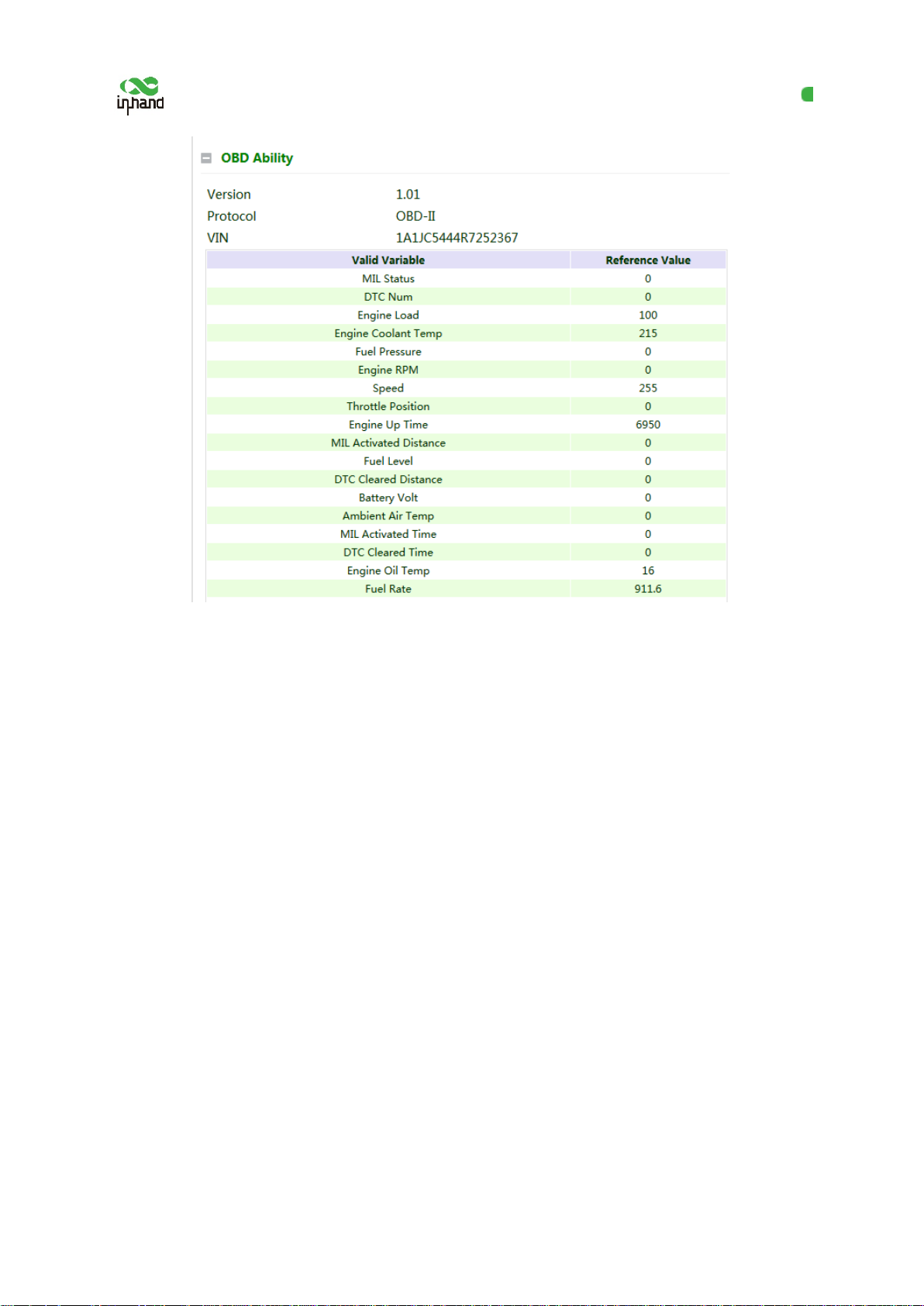
OBD Ability:
Version of the OBD ability;
Type of the OBD protocol;
Vehicle identification number (VIN);
Valid variables and reference values that can be collected by the gateway.
17
Page 23
InHand VG710 InVehicle Gateway User Manual
5.3 VPN Application
The VPN is intended to establish a private network on the public network for encrypted
communication. A VPN gateway enables remot e access by encrypting data packets and converting the
destination address of data packets. The VPN can be realized by a server, hardware, o r software, or in
other ways. Compared with the traditio nal DDN private line or frame relay, the VPN provides a more
secure and convenient remote access solution.
Common VPN application scenario: For example, an employee on a business trip accesses the
enterprise's intranet. The employee connects to the enterprise's VPN server and then accesses the
enterprise's intranet through the VPN server. Communication data between the VPN server and the
client is encrypted and can be regarded as being transmitted on a dedicated data network. This ensures
data security.
5.3.1 IPsec
IPsec is a group of open network security protocols developed by IETF. At the IP layer, the data
source authentication, data encryption, data integrity, and anti-replay functions are used to ensure the
18
Page 24
InHand VG710 InVehicle Gateway User Manual
security of data transmission between communication parties on the Internet. This reduces the risk of
leakage and eavesdropping, ensures the integrity and confidentiality of data, and ensures the security
of service transmission for users.
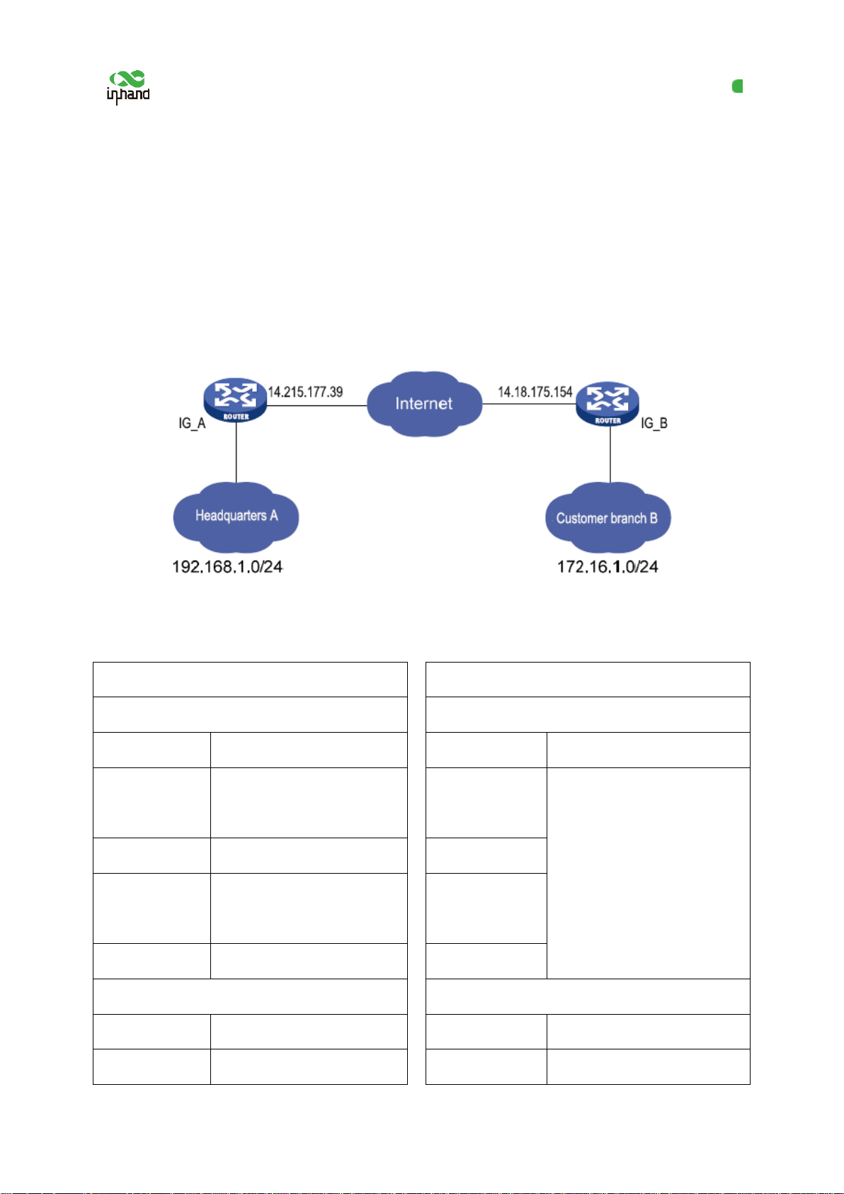
Scenario: Data is transmitted between the subnet (192.168.1.0/24) of headquarters A and the subnet
(172.16.1.0/24) of customer branch B through gateway A and gateway B. The transmission channels
of gateway A and gateway B are encrypted over IPsec, to protect the security of data t r ansmission
between headquarters A and customer branch B.
Method for encrypting the transmission channels of gateway A and gateway B ov er IPsec:
Parameter settings:
Gateway A Gateway B
Set IKEv1/v2 parameters Set IKEv1/v2 parameters
ID Custom
Encryption
AES128
algorithm
Hash algorithm SHA1
ID Custom
Encryption
algorithm
Hash algorithm
Same as that of gateway A
Diffie-Hellman
Group2
key exchange
Lifecycle 86400
Diffie-Hellman
key exchange
Lifecycle
IPsec policy IPsec policy
Name Custom
Encapsulation ESP
Name Custom
Encapsulation Same as that of gateway A
19
Page 25

InHand VG710 InVehicle Gateway User Manual
Address where gateway B
gateway A
IP address of the subnet of
IP address of the subnet of
Encryption
AES128
algorithm
Authentication
SHA1
method
IPsec mode Tunnel mode
Encryption
algorithm
Authentication
method
IPsec mode
IPsec tunnel configuration IPsec tunnel configuration
Address where
Peer address
establishes the IPsec service
Interface for establishing the
Interface
IPsec service
IKE version IKE version used
Authentication
Shared key
method
Peer address
Interface
IKE version
Authentication
method
establishes the IPsec service
Interface for establishing the
IPsec service
Same as that of gateway A
IP address of the subnet of
Local subnet
Local subnet
gateway A
IP address of the subnet of
Peer subnet
Peer subnet
gateway B
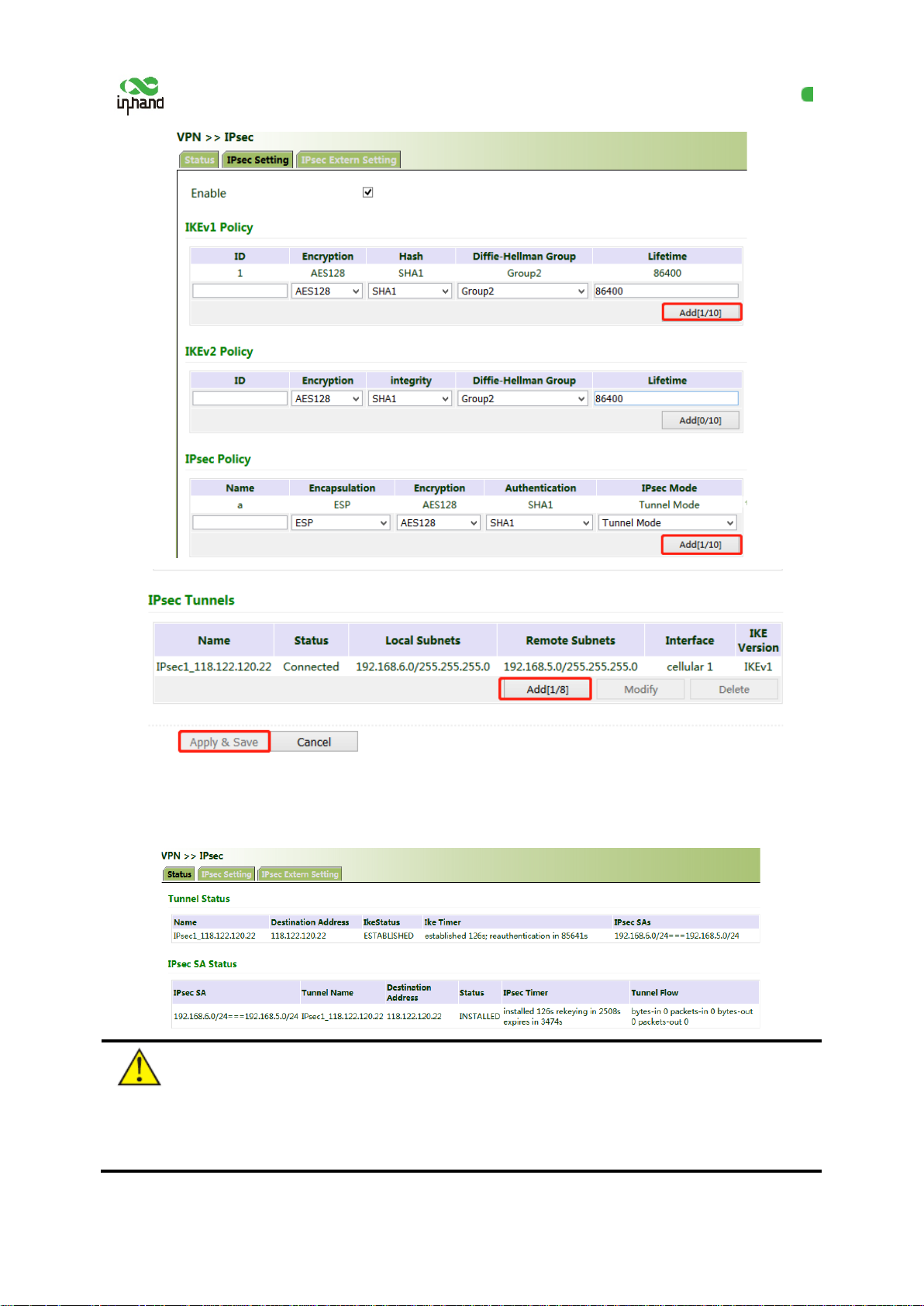
Detailed configuration steps:
1. Configure gateway A and gateway B.
(1) Add IKE and IPsec policies, and click Apply & Save.
(2) Add IPsec tunnels and click Apply & Save.
gateway B
gateway A
20
Page 26
InHand VG710 InVehicle Gateway User Manual
2. Access the IPsec status page. The IPsec VPN i s established successfully if the page i s shown as
below.
Note:
The IPsec profile does not need to be configured for establishing an IPsec VPN, but needs to be configured
for establishing a DM VPN.
21
Page 27
InHand VG710 InVehicle Gateway User Manual
5.3.2 GRE
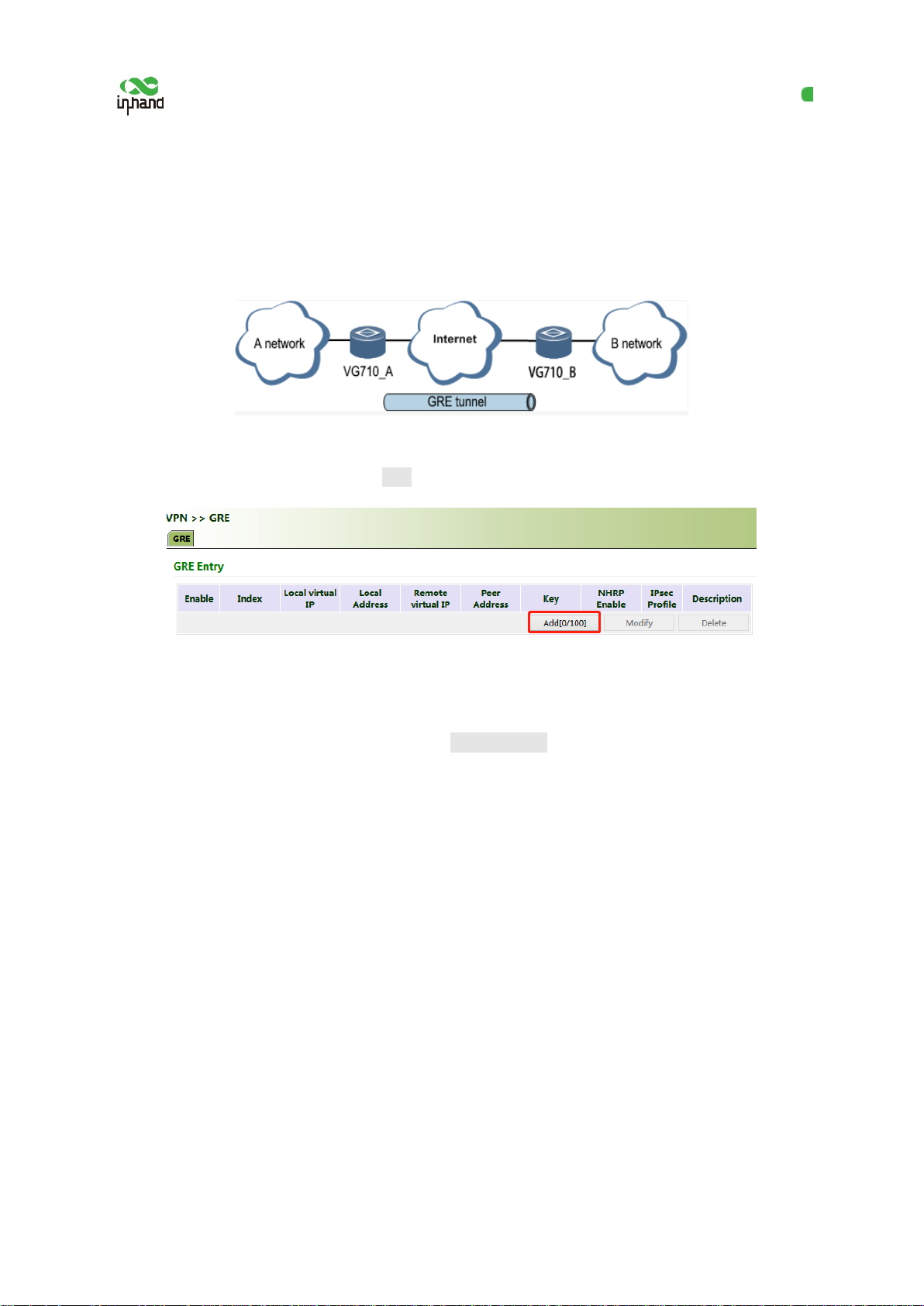
The Generic Routing Encapsulation (GRE) protocol can be used to encapsulate datagrams of some
network layer protocols, so that these en capsulated datagrams can be transmitted on the IPv4 network.
Scenario: GRE is enabled for VG710_A and VG710_B through the public network.
Method for enabling GRE for transmission channels of VG710_A and VG710_B:
1. Click "VPN >> GRE" and then click Add.
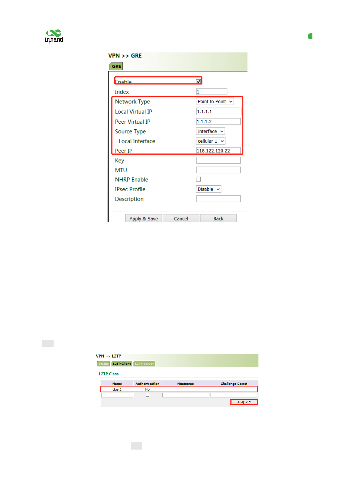
2. Set "Index" as required. Select "Point to Point" or "Subnet" for "Network Type". Set "Local Virtual
IP" and "Peer Virtual IP", ensuring that they are on the same network segment. Enter the source and
peer IP addresses or interfaces and the key. Click Apply & Save.
22
Page 28
InHand VG710 InVehicle Gateway User Manual
3. Set VG710_B in the same way. The virtual and peer IP addresses of VG710_B must correspond to
those of VG710_A, and the key must be the same as that of VG710_A.
5.3.3 L2TP
The Layer 2 Tunneling Protocol (L2TP) is an industrial-standard Internet tunneling protocol used to
encrypt network data streams.
Method for settings when the gateway is used a s an L2TP client:
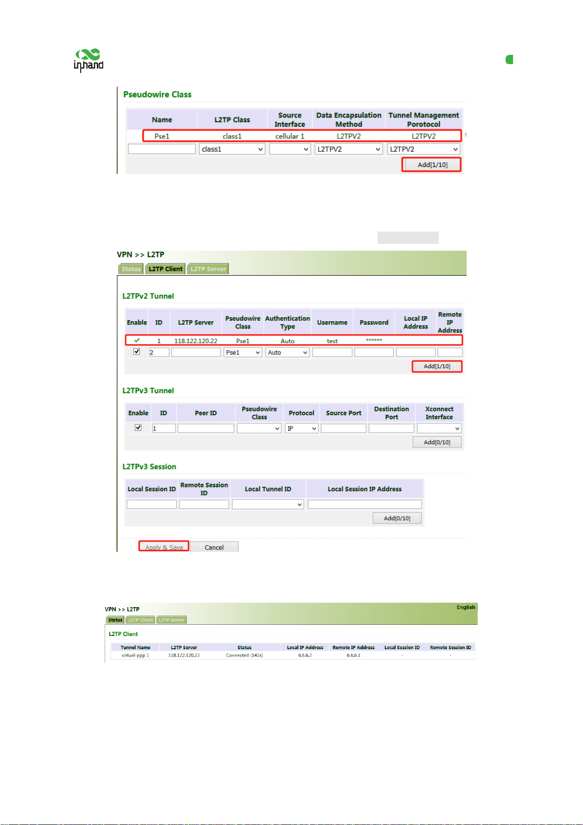
1. Click "VPN >> L2TP >> L2TP Client >> L2TP Class", enter a name of an L2TP class, and click
Add.
2. Configure the pseudowire class: Enter a name of any pseudowire class. "L2TP Class" is the same as
that on the "L2TP Class" page. Set "Source Interface" to the interface connecting to the server. Select
L2TPV2 for "Protocol" and click Add.
23
Page 29
InHand VG710 InVehicle Gateway User Manual
3. Set L2TPV2 tunnel parameters: Enter the server's domain name or IP address for "L2TP Server".
"Pseudowire Class" is the same as that on the "Pseudowire Class" page. Enter the user name and
password created on the server. Set oth er parameters as required. Click Apply & Save.
4. After gateway A and gateway B are configured, access the L2TP status page to view the L2TP
connection status.
24
Page 30
InHand VG710 InVehicle Gateway User Manual
password created on the OpenVPN server, click
name/password
Certificate Management", and import the CA certificate, public key, and
name/password
server, click "VPN >> Certificate Management", and import the CA
5.3.4 OpenVPN
OpenVPN is realized based on the app lication-layer VPN of the OpenSSL library. It supports multiple
authentication methods such as the certificate, key, and user name/password. Compared wi th the
traditional VPN, it is simpler and easier to use.
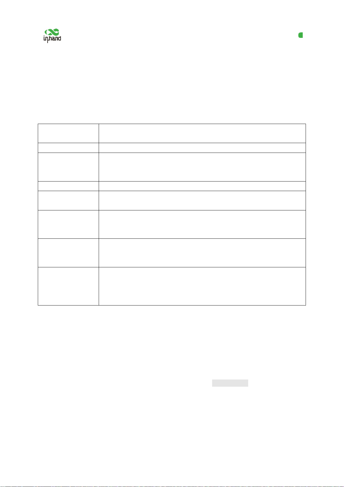
Authentication methods:
Authentication
method
None
User
name/password
Pre-shared key
Digital certificate
Digital
certificate/user
Digital
certificate/TLS
authentication
Digital
certificate/TLS
authentication/user
Operation on the web page
No authentication is required.
Enter the user name and
"VPN >> Certificate Management", and import the CA certificate, public key,
and private key for authentication.
Enter the pre-shared key created on the OpenVPN server.
Click "VPN >> Certificate Management" an d import th e CA certificate, pub lic
key, and private key.
Enter the user name and password created on the OpenVPN server, click
"VPN >> Certificate Management", and i mport the CA certificate, public key,
and private key for authentication.
Enter the pre-shared key created on the OpenVPN server, click "VPN >>
private key for authentication.
Enter the pre-shared key, user name, and password created on the OpenVP N
certificate, public key, and private key for authentication.
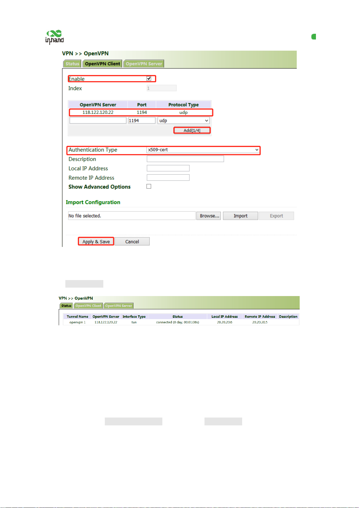
Method for settings when the gateway is conn ect ed to the OpenVPN server as a client:
OpenVPN can be configured manually, or OpenVPN configurations can be imported. In the following
example, the authentication type is a digital certificate.
1. Set the OpenVPN parameters for the gateway as shown in the figure below, ensuring that the
network parameters at both ends of the tunnel are consistent. Click Apply & Save.
25
Page 31
InHand VG710 InVehicle Gateway User Manual
2. Select a digital certificate for "Authentication Type", click "VPN >> Certificate Management", and
import the CA certificate, public key, and private key.
3. Click Apply & Save. Return to the "Status" page and view the tunnel status.
5.3.5 Certificate Management
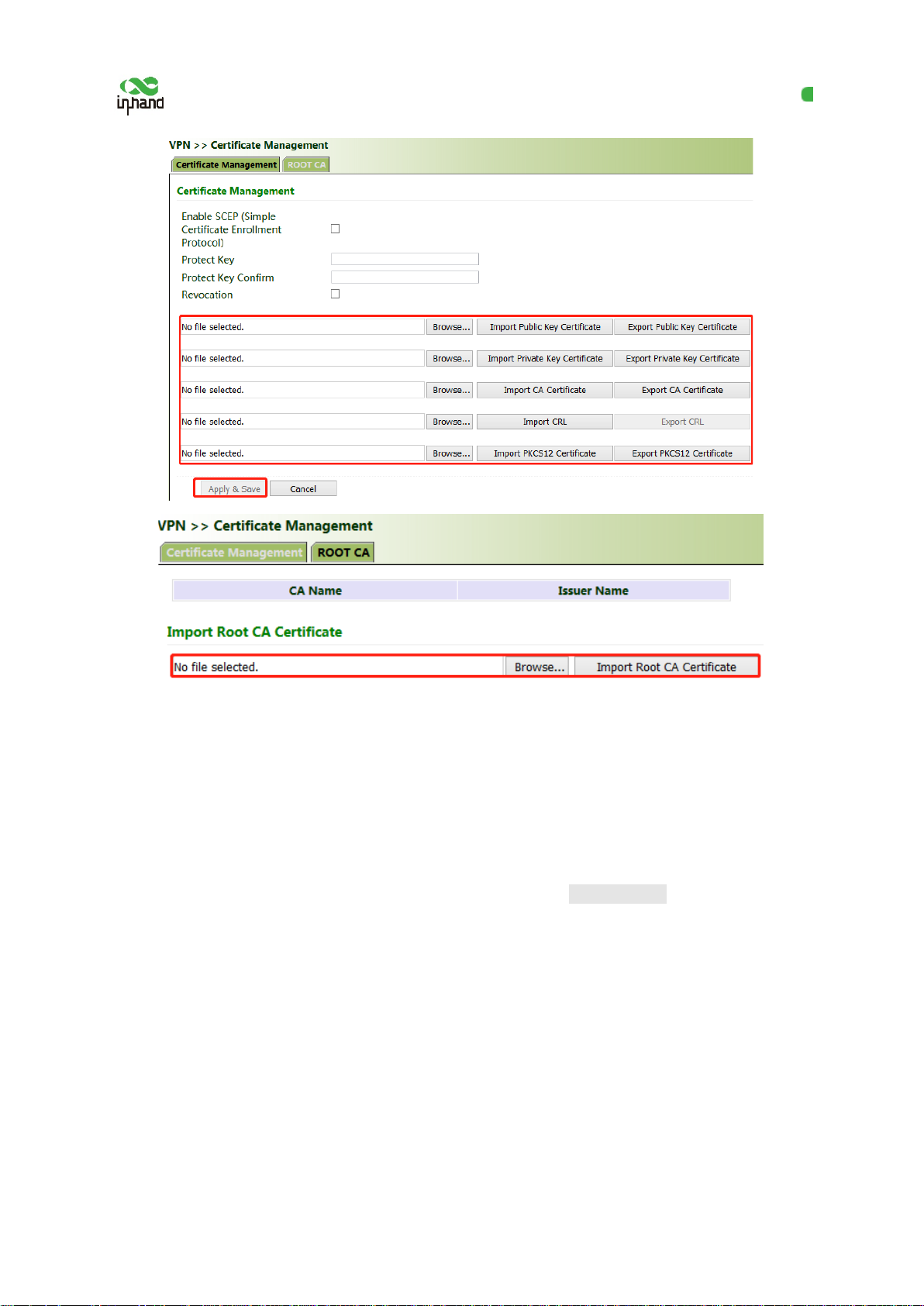
Certificates can be imported or exported on this page. Certificates are used for IPsec and OpenVPN
services.
Method for importing a certificate:
Click "VPN >> Certificate Management >> B r owse", select the certificate obtained from the
certificate server, click Import XX Certificate, and then click Apply & Save.
26
Page 32
InHand VG710 InVehicle Gateway User Manual
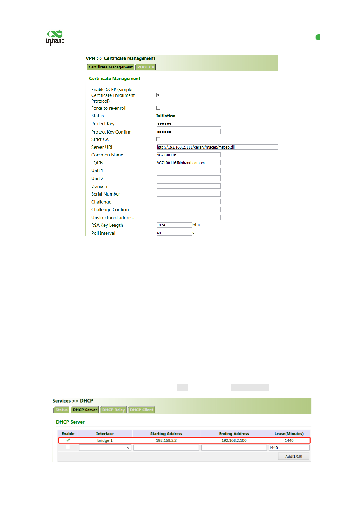
If no local certificate is available, check "Enable SCEP (Simple Certificate Enrollment Protocol)" to
apply for a certificate online.
Method for applying for a certificate for the gateway online:
1. Click "VPN >> Certificate Managem ent". Check "Enable SCEP (Simple Certificate Enrollment
Protocol)" and "Force to re-enroll". Enter the certificate protection key and confirm it. Enter the URL
of the certificate server, the certificate name, and the FQDN. Click Apply & Save.
2. After the server issues the certificate, check the application status. If the application status is
"Completion", the certificate applicati on succeeds.
27
Page 33
InHand VG710 InVehicle Gateway User Manual
5.4 Services
5.4.1 DHCP (Automatic IP Address Allocation)
DHCP uses the client/server communication mode. The client submits a configuration application to
the server, and the server returns the IP address assigned to the client to realize the dynamic
configuration of the IP address.
The DHCP server and DHCP forwarding function are mutually exclusive.
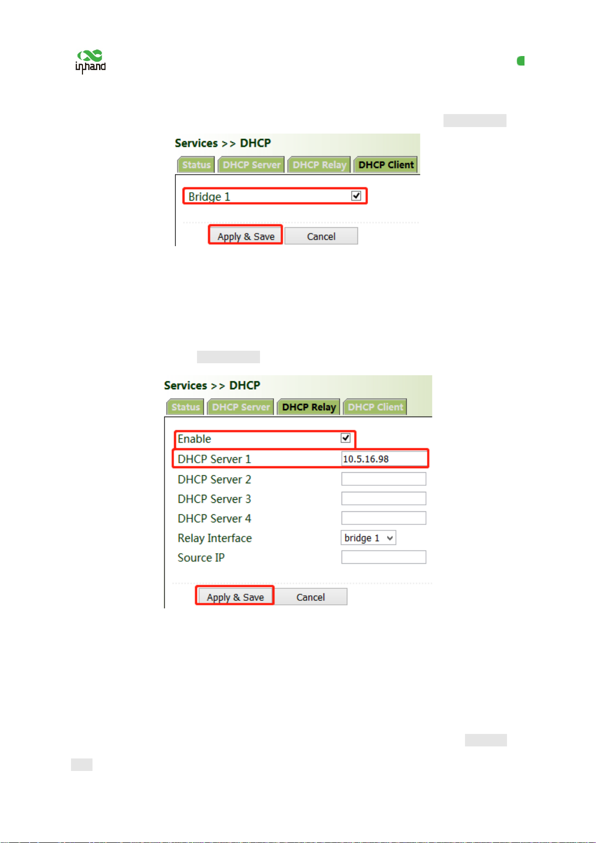
Method for settings when the gateway is used a s a DHCP server:
Click "Services >> DHCP >> DHCP Server" . In the "DHCP Server" bar, check "Enable" , select an
interface, set the start and end IP addresses, click Add, and then click Apply & Save.
28
Page 34
InHand VG710 InVehicle Gateway User Manual
Method for settings when the gateway is used as a DHCP client:
Click "Services >> DHCP >> DHCP Client ", select the gateway interface, and click Apply & Save.
Method for enabling DHCP forwarding for the gateway:
DHCP forwarding is also referred to as a DHCP relay agent. It can process and forward DHCP
information between different subnets and physical network segments.
Click "Services >> DHCP >> DHCP Relay", check "Enable", enter the server addr ess, select the
gateway interface, and click Apply & Save.
5.4.2 DNS
The domain name service (DNS) is a distributed network directory service mainly used for mutual
conversion between a domain name and an IP address.
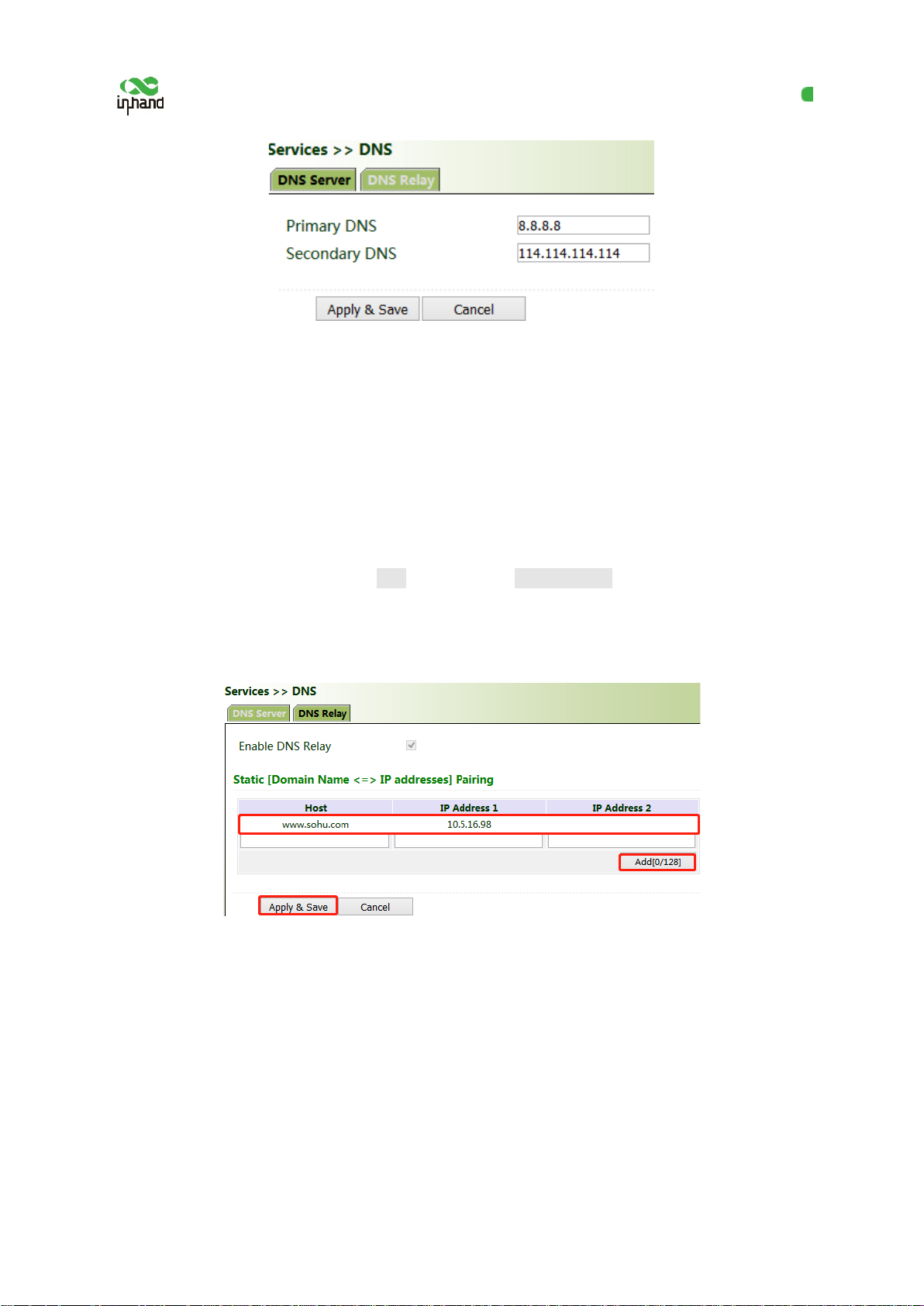
Method for enabling the DNS server for the g ateway:
Click "Services >> DNS >> DNS Server", enter the address of the DNS server, and click Apply &
Save.
29
Page 35
InHand VG710 InVehicle Gateway User Manual
Method for enabling DNS forwarding for t he gateway:
As a DNS agent, the gateway forwards DNS request and response messages between the DNS client
and the DNS server, and replaces the DNS clien t for domain name resolution.
If the DHCP service is enabled for the gateway, DNS forwarding is enabled by default and
cannot be disabled.
Click "Services >> DNS >> DNS Relay", check "Enable DNS Relay", set the mapping betwee n the
domain name and the IP address, click Add, and then click Apply & Save. After the setting s ar e
completed, when a DNS client on the LAN requests a host domain name in the list, the DNS agent
server returns the corresponding IP address to the client.
5.4.3 DDNS
The dynamic domain name server (DDNS) maps the dynamic IP address of the gateway to a fixed
DNS. Each time a user connects to the Internet, the client program transmits the dy namic IP address of
the host to the server program on the server host through information transfer. The server program
provides the DDNS service and realizes dynamic domain name resolution. In this way, you can access
the Internet by entering the domain name, even if the IP address is changed.
30
Page 36
InHand VG710 InVehicle Gateway User Manual
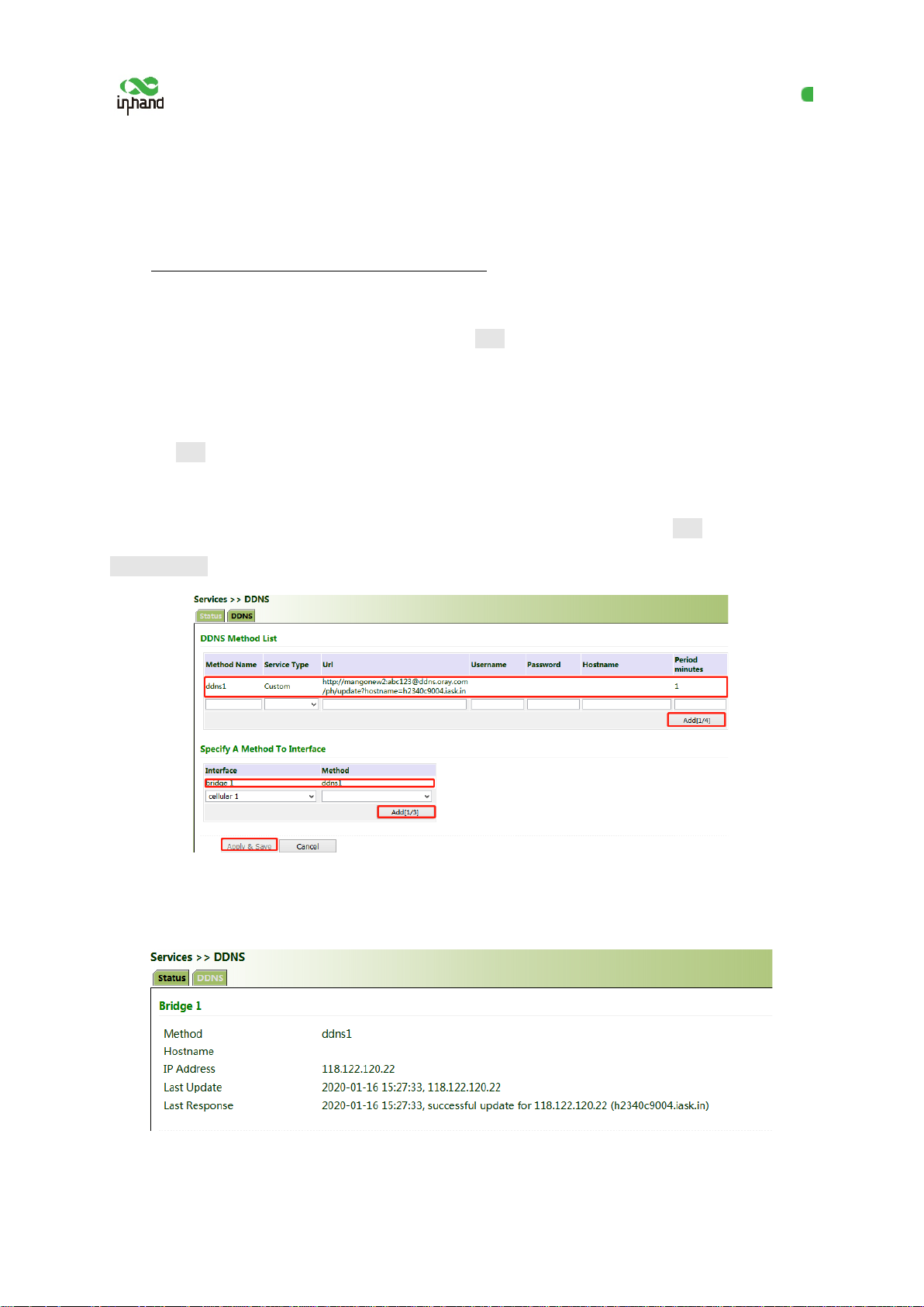
Method for enabling the DDNS service for the gateway:
1. If the Custom service is used, set "Method Name" as required, select "Custom" for "Service Type",
and enter the DDNS expression "http://user
name:[email protected]/ph/update?hostname=
host name" of the server for "Url". This
expression is only for reference. The actual URL is provided by the service provider (usually available
on the official website of the service pro vider). Click Add.
If a common domain name server other than the Custom service is used, set "Method Name" and
"Service Type" as required, enter the user name, password, and host name obtained from the ser ver,
and click Add.
If "Disable" is selected, the DDNS service is not used.
2. Select the gateway interface, enter the name of the DDNS update method, click Add, and then click
Apply & Save to apply the DDNS update method to the gateway interface.
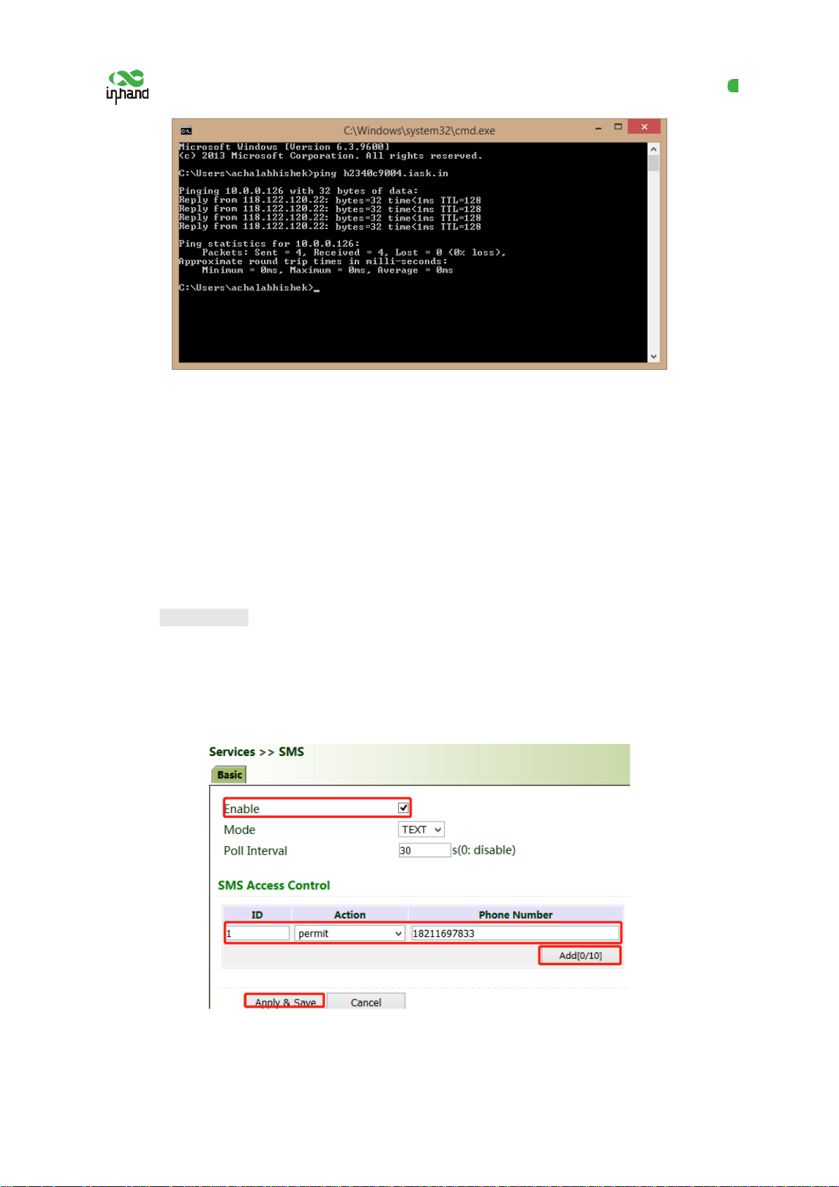
3. Wait several minutes after the DDNS settings are applied and saved. Then ping the h ost name
(domain name) of the domain name server to confirm the successful application of the DDNS service.
31
Page 37
InHand VG710 InVehicle Gateway User Manual
5.4.4 SMS
The short message service (SMS) is enabled for gateway restart and manual dialup via S MS messages.
Some gateways can receive alarm information in the SMS whitelist.
Method for controlling gateway restart an d manual dialup via SMS messages
When the cellular selects SMS activation mode, Click "Servi ces >> SMS" and check "Enable". In the
"SMS Access Control" bar, set "ID" as required, select "permit" for "Action" , enter the phone number,
and click Apply & Save. When you activate the dialup port via SMS, after the configuration is
completed, you can send the reboot command to restart the gateway by using the mobile phone
number, or send the cellular 1 ppp up/down command to make the gateway redial or interrupt the
dialup.
32
Page 38
InHand VG710 InVehicle Gateway User Manual
5.4.5 GPS
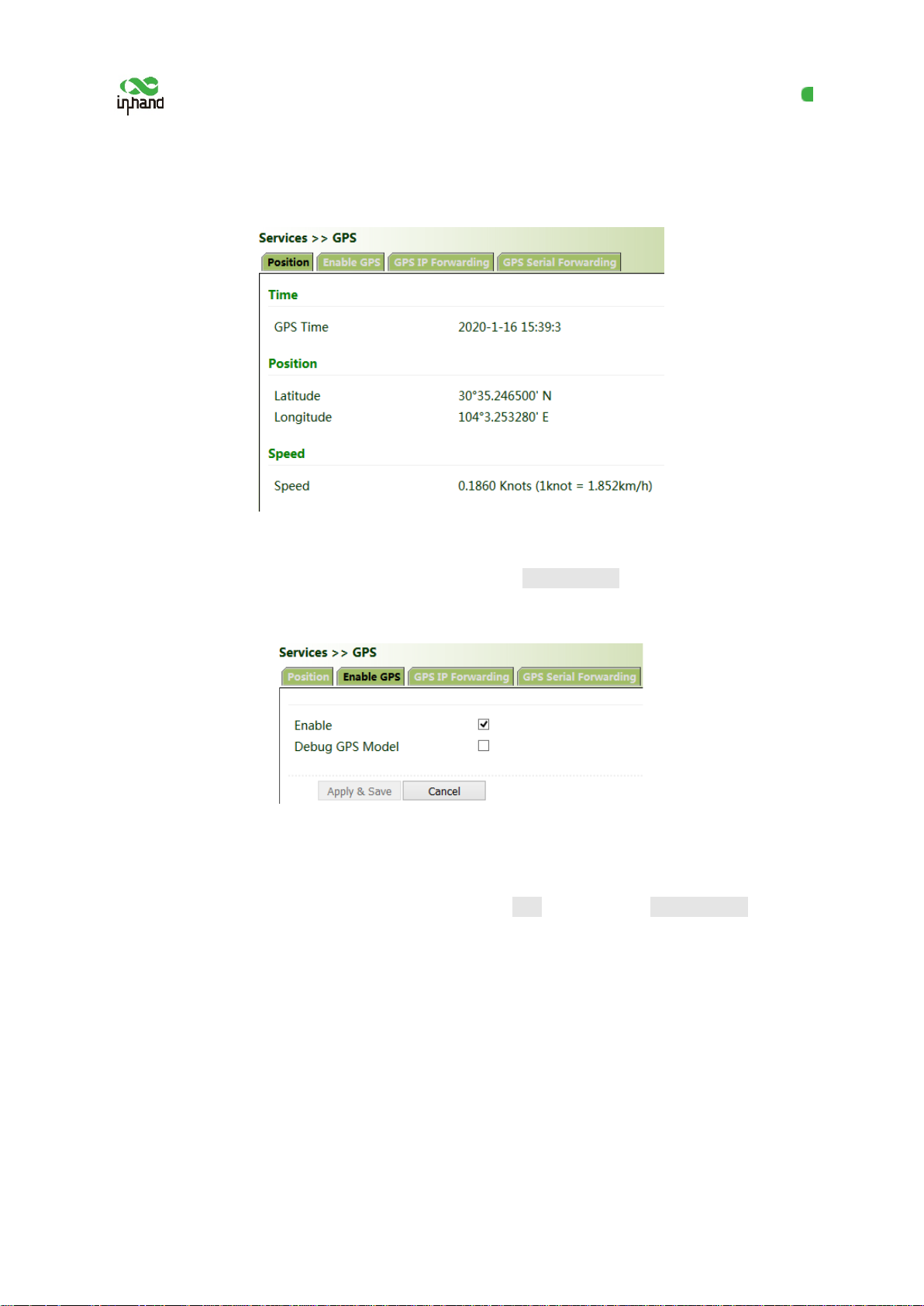
Position: You can view the current positioning information.
Method for enabling GPS for the gateway:
Click "Services >> Enable GPS", check "E nable", and click Apply & Save. By default, GPS is enabled
for the gateway.
Method for forwarding GPS data to the server over IP when VG710 is used as a client:
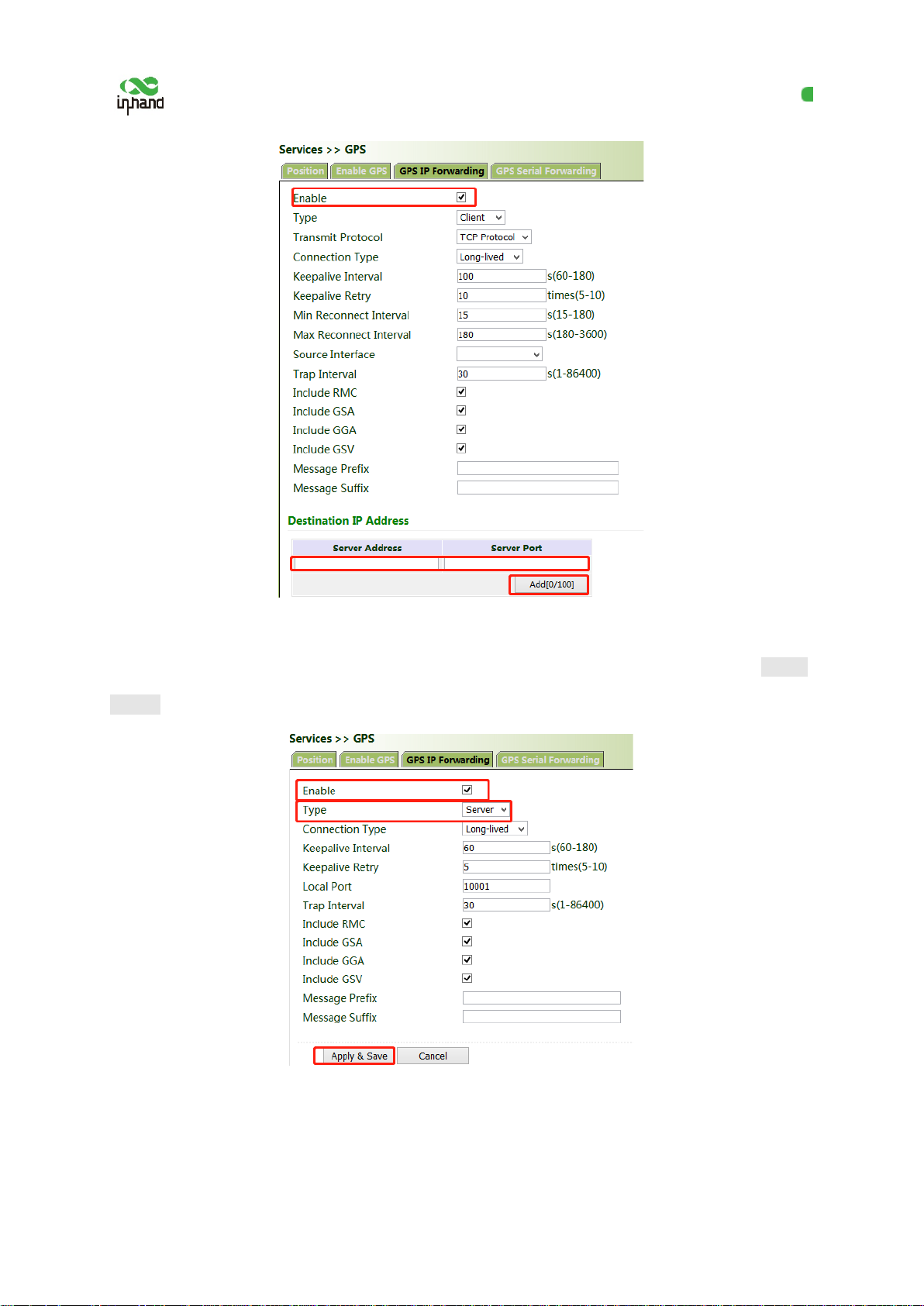
Click "Services >> GPS IP Forwarding", check "Enable", select "Client" for "Type", enter the server
address and port in the "Destination IP Address" bar, click Add, and then click Apply & Save.
33
Page 39
InHand VG710 InVehicle Gateway User Manual
Method for forwarding GPS data over IP when VG 710 is used as a server:
Click "Services >> GPS IP Forwarding", check "Enable", select "Server" for "Type" , and click Apply
& Save.
Method for forwarding GPS data by VG710 through a serial port:
34
Page 40

InHand VG710 InVehicle Gateway User Manual
Click "Services >> GPS Serial Forwardin g", check "Enable", and select a serial por t type based on the
data transmission port used. Ensure th at the baud rate, data bits, parity bit, and stop bit are the same as
the current settings. Click Apply & Save.
5.4.6 QoS
Quality of service (QoS) is a network secur ity mechanism that enables a network to provide better
services for designated network communication by using various basic technologies. It is a technology
for solving problems such as network delays and blocking.
Method for setting the egress maximum bandwidth for the gateway through QoS control:
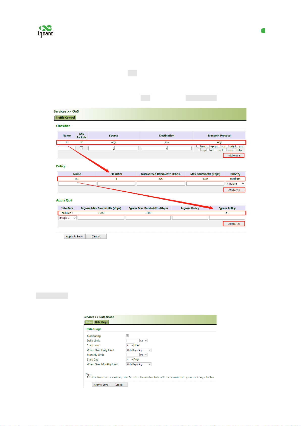
Click "QoS >> Traffic Control >> Apply QoS", select the gateway interface, enter the egress
maximum bandwidth, click Add, and then click Apply & Save.
Method for applying the ingress and egress policies for the gateway through QoS control:
1. Add a network link classifier. Click "Qo S >> Traffic Control >> Classifier", check " Any Packets",
set the source and destination addresses of the link, select transmit protocols for QoS control, and click
Add.
35
Page 41
InHand VG710 InVehicle Gateway User Manual
2. Set transmission policies. Click "QoS >> Traffic Control >> Policy", enter a custom policy name
for "Name", enter the classifier name for "C lassifier", set the guaranteed bandwid th, maximum
bandwidth, and policy priority, and click Add.
3. Click "QoS >> Traffic Control >> Apply QoS", select the gateway interface, enter th e policy name
for "Ingress Policy" and "Egress Policy", click Add, and then click Apply & Save.
5.4.7 Traffic Control
Method for enabling traffic control for the gateway:
Click "Services >> Traffic Control" , enable traffic control, set traffic control para meter s, and click
Apply & Save. After the settings are completed, the system generates an alarm, stops forwarding, or
disables the interface when the traffic exceeds t he limit according to the settings on this page.
36
Page 42
InHand VG710 InVehicle Gateway User Manual
5.5 Firewall
5.5.1 ACL
The access control list (ACL) is an access control technology based on packet fi ltering. It can filter the
packets on the interface based on preset conditions and allow them to pass or discard them.
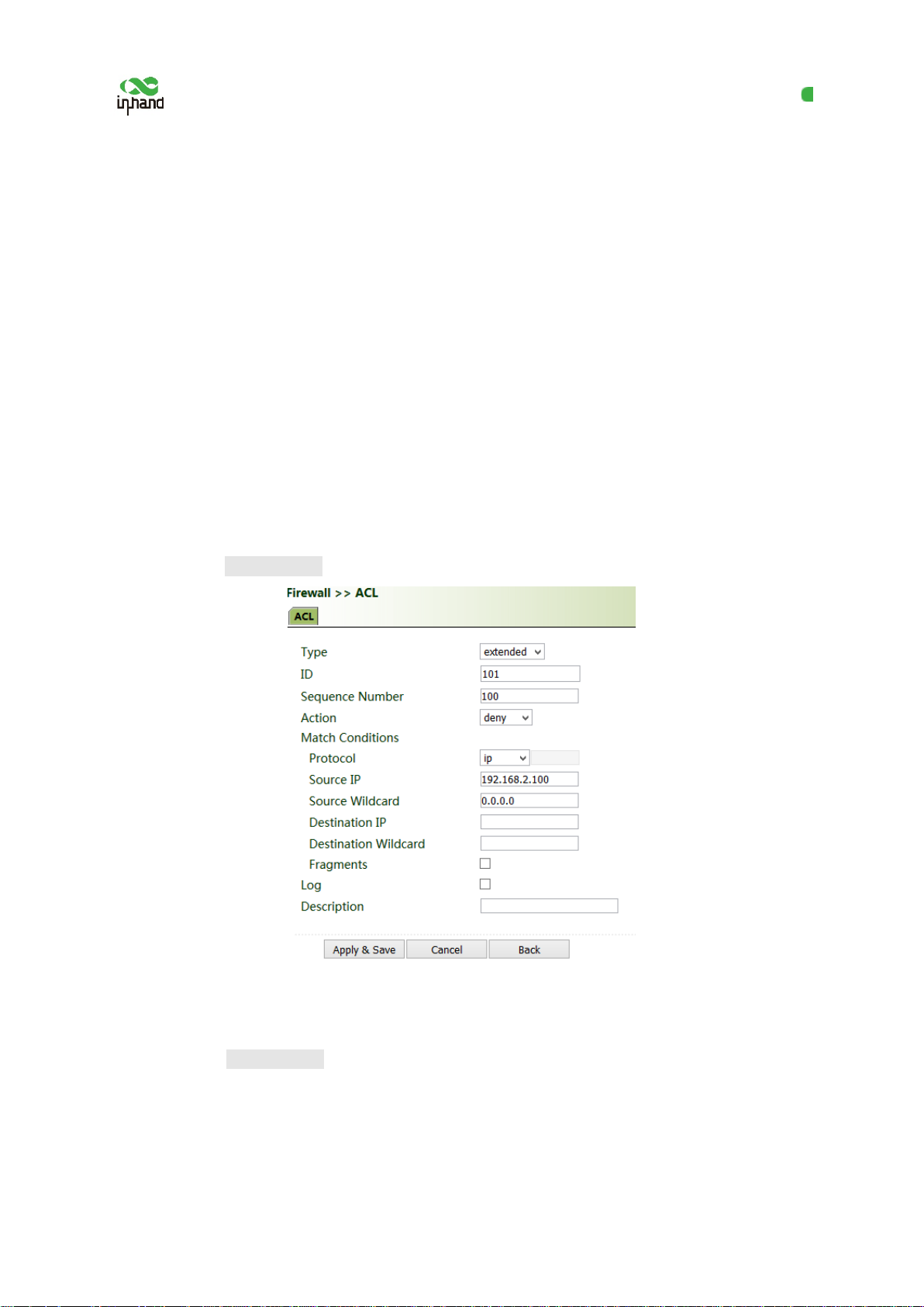
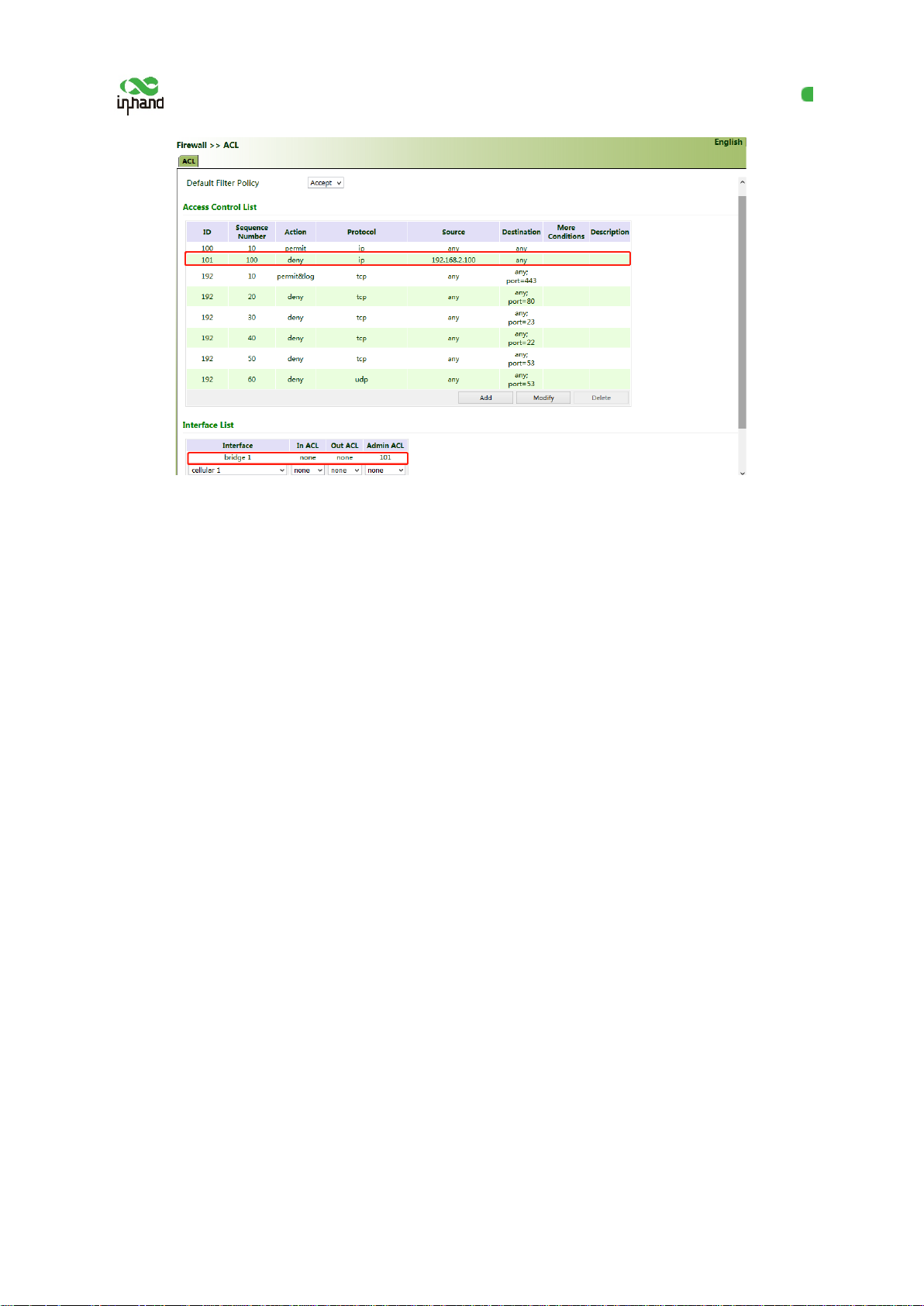
Common scenario: By default, all devices on the LAN (bridge 1) can access the Internet, except the
device with the IP address of 192.168.2.100.
Method for setting VG710:
1. Click "Firewall >> ACL >> Add". Enter the ID and sequence number. A smaller sequence number
indicates a higher priority. Select "deny" for "Action". Set "Source IP" to "192.168.2.100" and "Source
Wildcard" to "0.0.0.0". Leave "Destination IP" empty, which indicates 0.0.0.0/0, that is, all IP
addresses. Click Apply & Save.
2. Return to the ACL page, add the rule with the ID of 101 to the management rule of bridge 1, and
click Add. Click Apply & Save.
37
Page 43
InHand VG710 InVehicle Gateway User Manual
5.5.2 NAT
Network address translation (NAT) can be used when some hosts on a private network have been
assigned with local IP addresses (that is, private IP addresses used only on the privat e network), but
expect to communicate with hosts on the Internet (without encryption).
Common scenario: A user expects to access a camera on the LAN of the device through the public
network to view the current driving conditions of the vehicle. The camera address is 192.168.2.100,
and the open port 18000 provides video services.
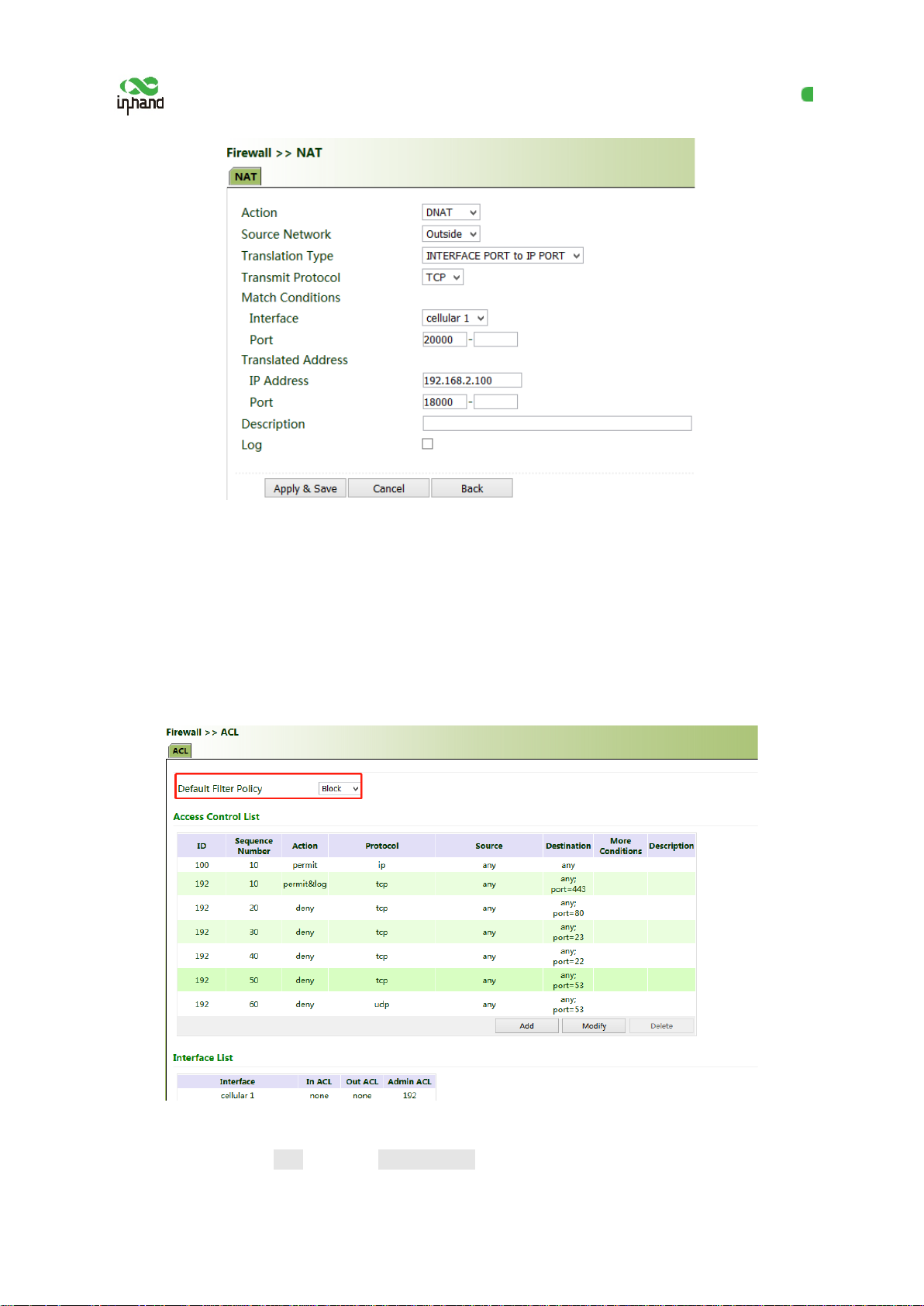
1. Click "Firewall >> NAT", and select "DNAT" for "Action", and "Outside" for "Sou r ce Network".
Select "IP PORT to IP PORT" or "INTERFACE PORT to IP PORT" for "Translation Type". The
public IP address obtained through dial-up is not fixed, so "INTERFACE PORT to IP PORT" is more
convenient. Select "TCP" for "Transmit Protocol" because video services are transmitted over T C P.
Select "cellular 1" (dialup interface for the cellular network) for "Interface" and set "Port" to "20000".
Set "IP Address" and "Port" under "Translated Address" to "192.168.200" and "18000" respectively.
Click Apply & Save.
The gateway redirects the TCP service destined for port 20000 of the cellular 1 interface to the internal
IP address 192.168.2.100 and port 18000, to enable access to the internal services.
38
Page 44
InHand VG710 InVehicle Gateway User Manual
5.5.3 MAC-IP Binding
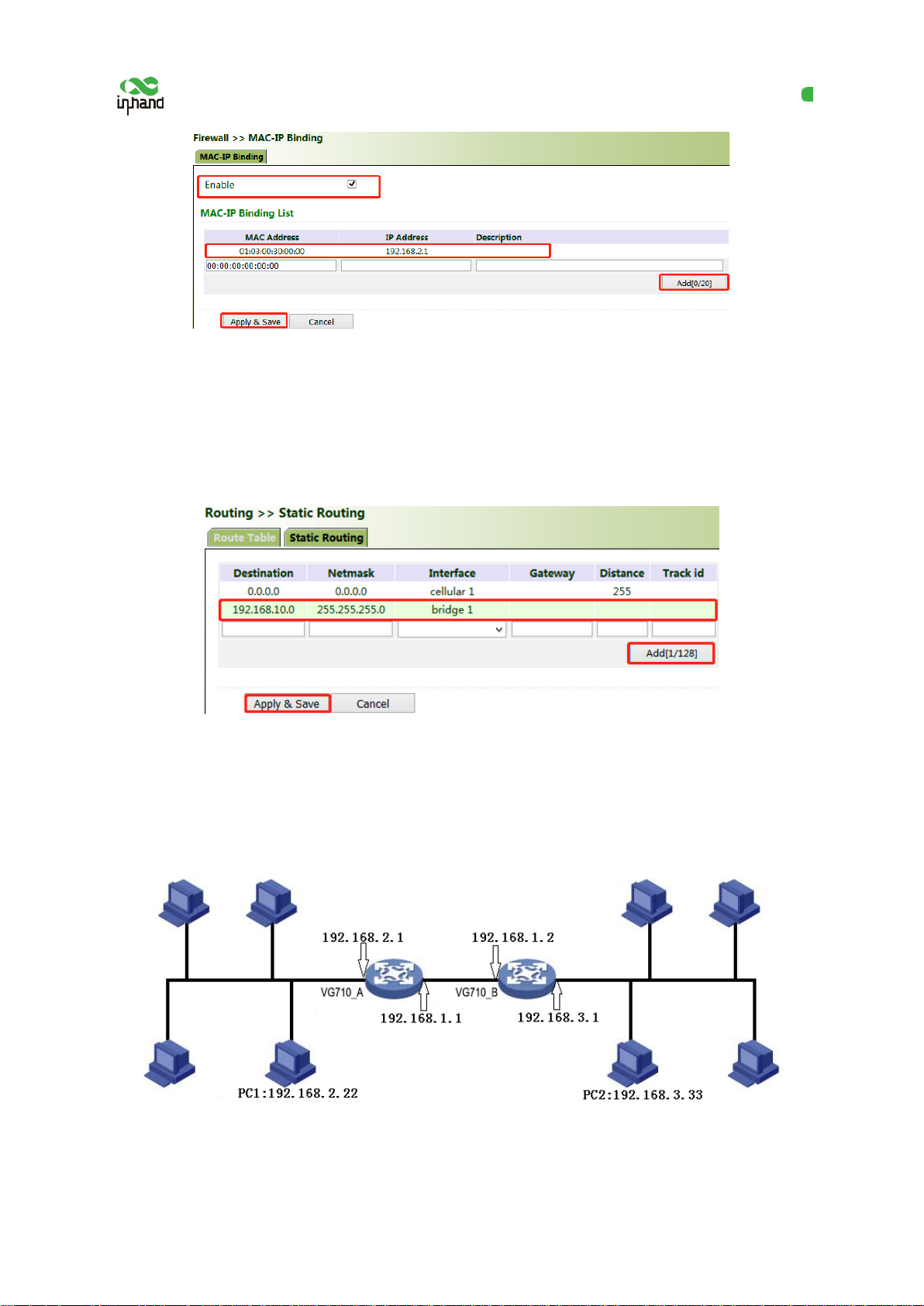
After MAC-IP binding, the PC can access the public network through the gateway only by using the
IP address bound to the MAC address of the PC.
Method for binding the MAC address and IP address of a connected device:
1. Click "Firewall >> ACL" and select "Block" for "Default Filter Policy".
2. Click "Firewall >> MAC-IP Binding", check "Enable", enter the MAC address and IP address of the
connected device, click Add, and click Apply & Save.
39
Page 45
InHand VG710 InVehicle Gateway User Manual
5.6 Routing
5.6.1 Static Routing
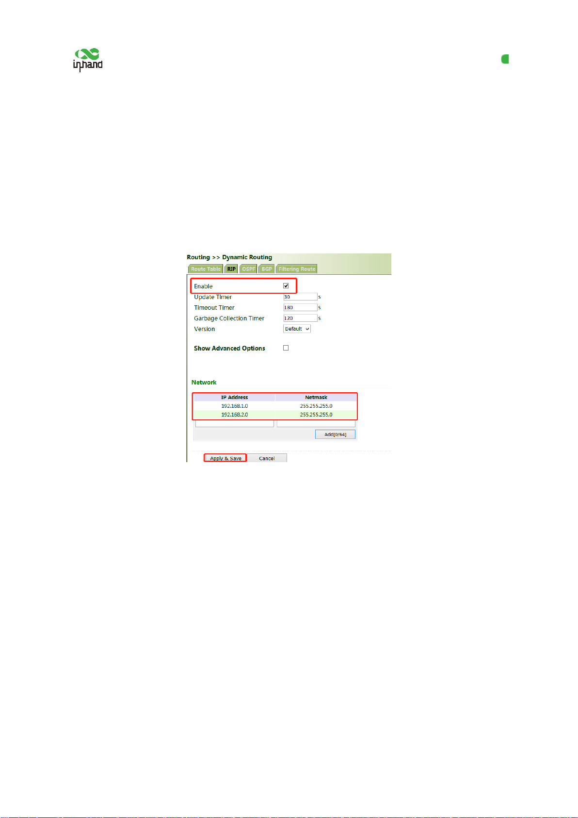
Set the destination network, subnet mask , and interface or gateway as required.
5.6.2 Dynamic Routing
Scenario: Enable dynamic routing between two LANs for mutual communication between them. The
topology is shown below.
40
Page 46
InHand VG710 InVehicle Gateway User Manual
5.6.2.1 RIP
The Routing Information Protocol (RIP) is a simple internal dynamic routing protocol mainly used on
small-scale networks.
Method for enabling dynamic routing between VG710_A and VG710_B over RIP in the
scenario:
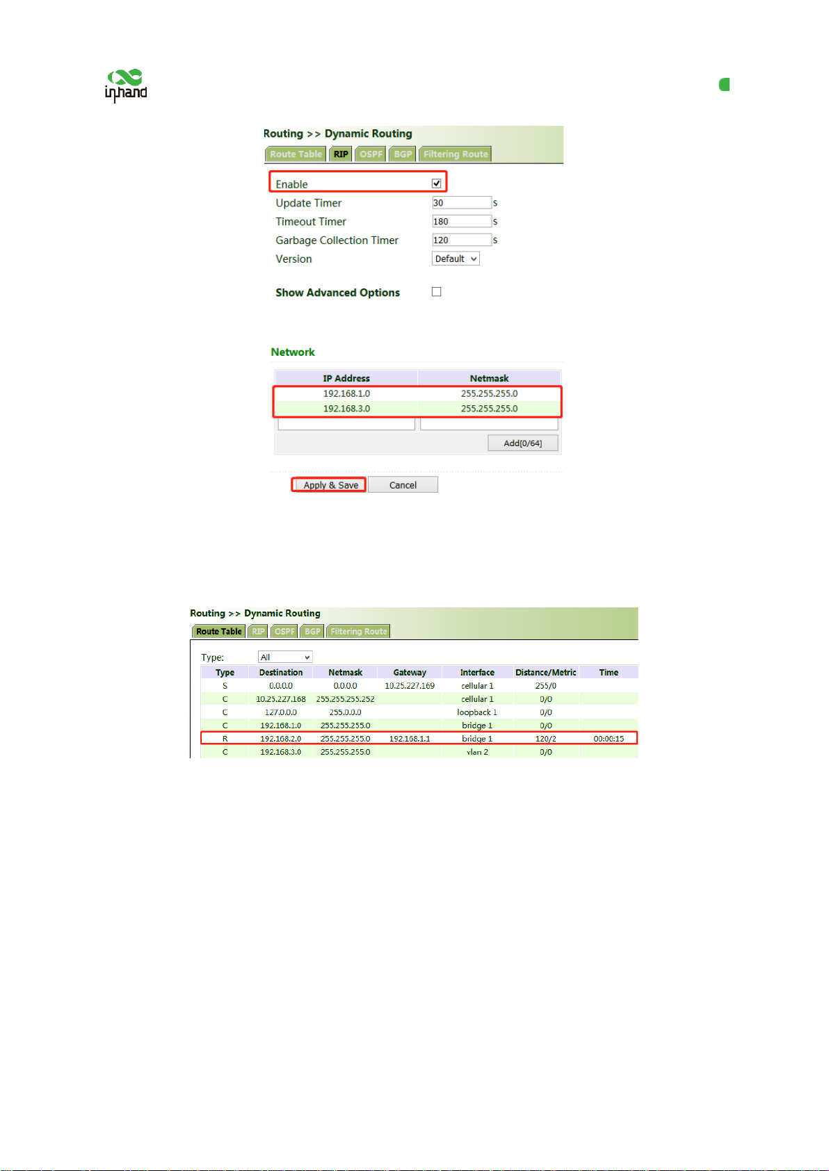
1. Configure VG710_A. Click "Routing >> Dynamic Routing >> RIP", check "Enable", and configure
VG710_A in the "Network" bar to announce the routing entry of VG710_A.
2. Configure VG710_B.
41
Page 47
InHand VG710 InVehicle Gateway User Manual
3. After the configuration is completed, check whether PC 1 can communicate with PC 2. If yes, the
dynamic route is added successfully. The RIP route learned by VG710_B is shown in the figure
below.
5.6.2.2 OSPF
The Open Shortest Path First (OSPF) protocol is a link-status-based internal gateway protocol mainly
used on large-scale networks.
Method for enabling dynamic routing between VG710_A and VG710_B over OSPF in the
scenario:
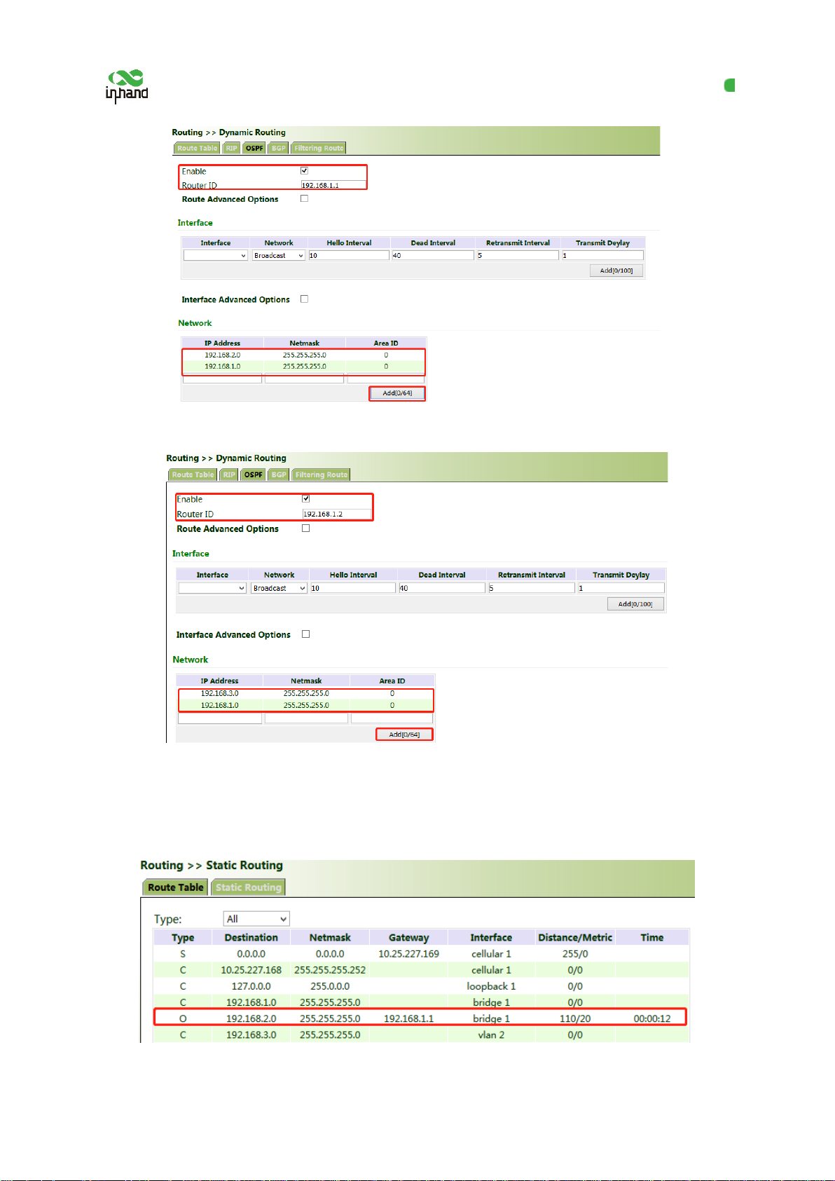
1. Configure VG710_A. Click "Routing >> Dynamic Routing >> OSPF", check "Enable", enter a
valid IP address for "Router ID", and configure VG710_A in the "Network" bar to announce the
routing entry of VG710_A.
42
Page 48
InHand VG710 InVehicle Gateway User Manual
2. Set parameters for VG710_B.
3. After the configuration is completed, check wh ether PC 1 can communicate with PC 2. If yes, the
dynamic route is added successfully. The OSPF r oute learned by VG710_B is shown in the figure
below.
43
Page 49
InHand VG710 InVehicle Gateway User Manual
5.6.2.3 BGP
Method for enabling dynamic routing between VG710_A and VG710_B over BGP in the
scenario:
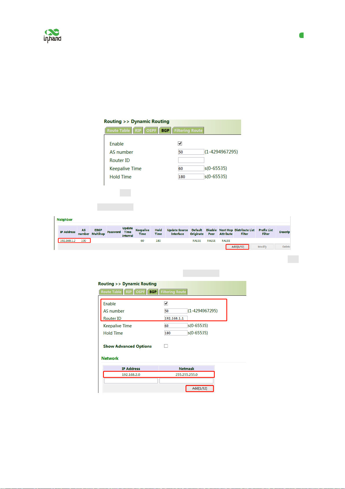
1. Configure VG710_A. Click "Routing >> Dynamic Routing >> BGP", check "Enable", and set "AS
number" as required.
2. In the "Neighbor" bar, click Add, enter the IP address 192.168.1.2 of VG710_B, set "AS number"
as required, and click Apply & Save.
3. Enter a valid IP address for "Router ID", configure VG710_A in the "Network" bar, and click Add,
to announce the routing entry of VG710_A. Then click Apply & Save.
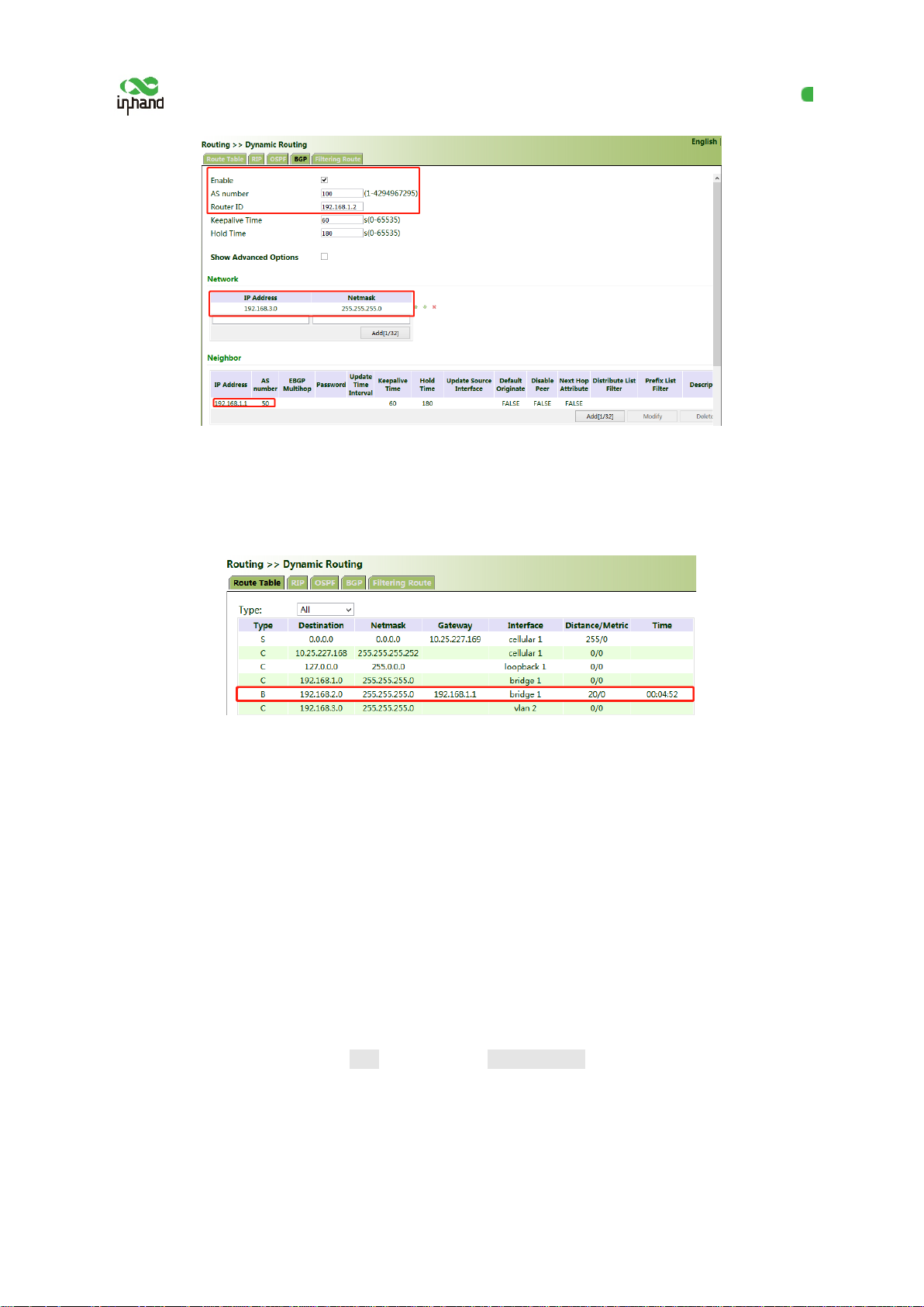
4. Set parameters for VG710_B. The parameters are the same as or corresponding to tho se of
VG710_A.
44
Page 50
InHand VG710 InVehicle Gateway User Manual
5. After the configuration is completed, check whether PC 1 can communicate with PC 2. If yes, the
dynamic route is added successfully. The BGP route learned by VG710_B is shown in the figure
below.
5.7 Link Backup
5.7.1 SLA
The service level agreement (SLA) is used to detect whether the link between the gateway and the ISP
fails.
Method for adding an SLA entry for the gateway:
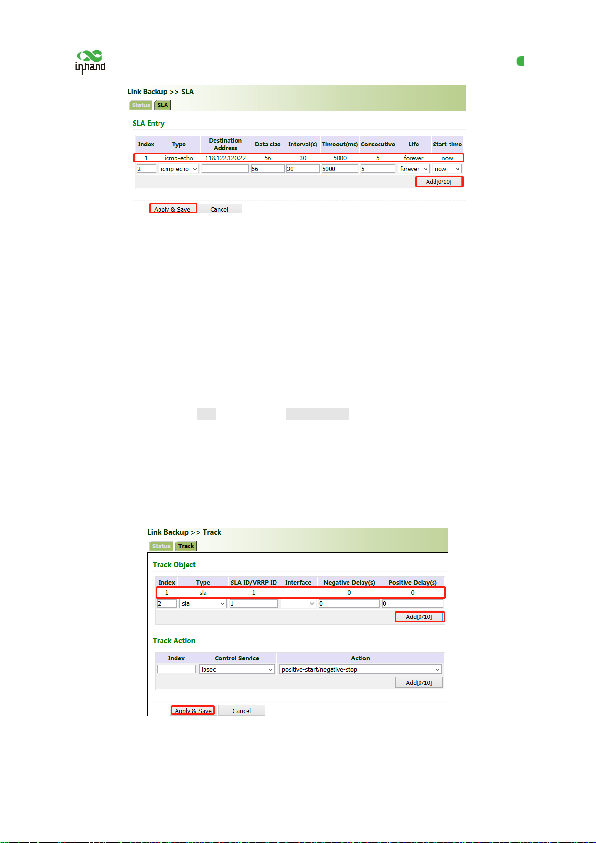
Click "Link Backup >> SLA >> Add", enter the detected IP address for "Destination Address", set
other parameters as required, click Add, and then click Apply & Save.
Timeout (ms) indicates the duration for determining a detection failure. Consecutive indicates the
number of detection failures resulting in a link failure.
45
Page 51
InHand VG710 InVehicle Gateway User Manual
5.7.2 Track
Currently, linkage is enabled between the track module and the following application modules: VRRP,
static routing, and interface backup. I f det ection succeeds, the corresponding track entry is in the
Positive state. If detection fails, the corresponding track entry is in the Negative state.
Method for adding a track entry for VG710:
Click "Link Backup >> Track >> Track", set "Index" as required, select "sla", "int er f ace", or "vrrp" for
"Type", set "SLA/VRRP ID" based on the ID in the SLA list, set "Negative Delay (s)" and "Positive
Delay (s)" as required, click Add, and then cli ck Apply & Save.
Negative Delay (s): In case of an abnormal state, switching can be delayed based on the delay setting
(0 indicates immediate switching).
Positive Delay (s): When a failure is reco vered, switching can be delayed based on t he delay setting (0
indicates immediate switching).
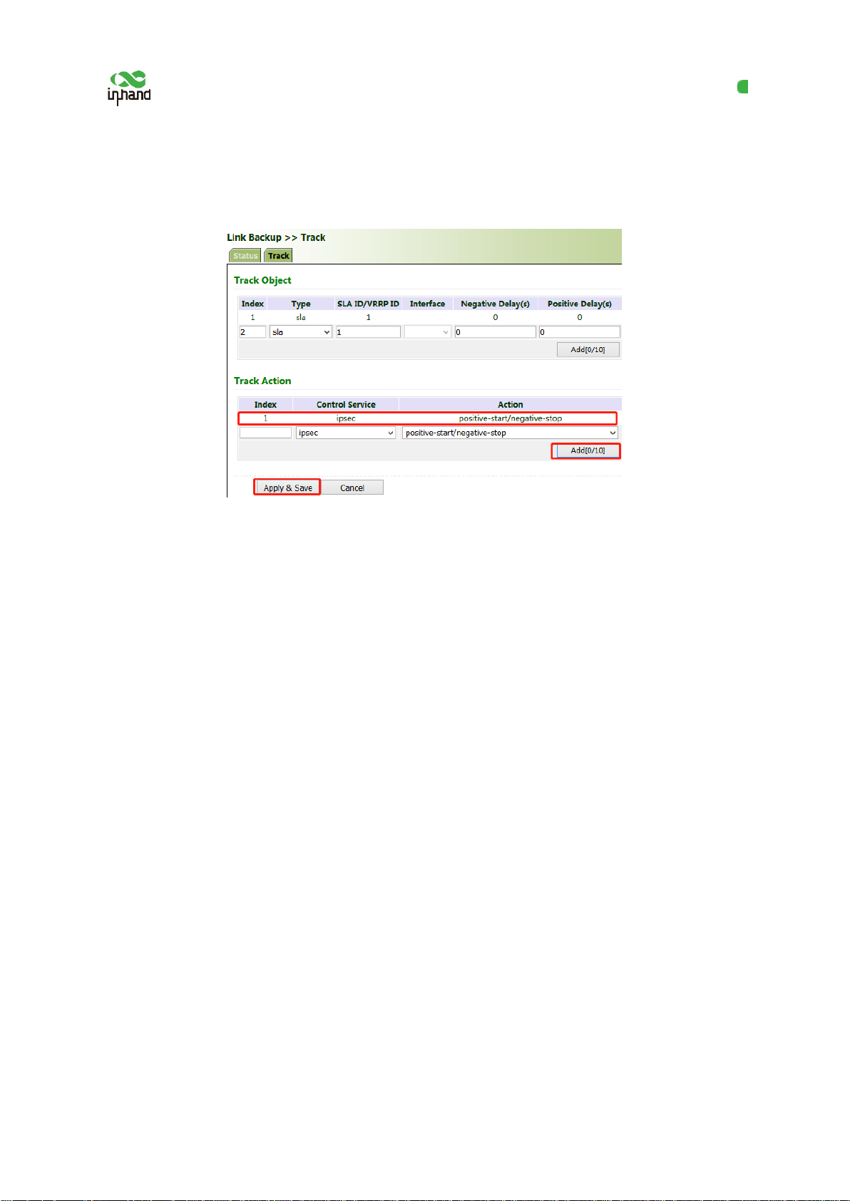
Method for adding an IPsec track entry f or VG710:
46
Page 52
InHand VG710 InVehicle Gateway User Manual
Click "Link Backup >> Track >> Track" and set "Index" as required. "positive-start/negative-stop"
means starting the IPsec service when the t r ack detection state is Positive and stopping the IPsec
service when the track detection state is Negative.
5.7.3 VRRP
Scenario: Multiple gateways are connected to a network at the same time. Gateway A acts as the host,
and gateway B acts as a backup for gateway A. When gateway A fails, gateway B temporarily
replaces gateway A as the host.
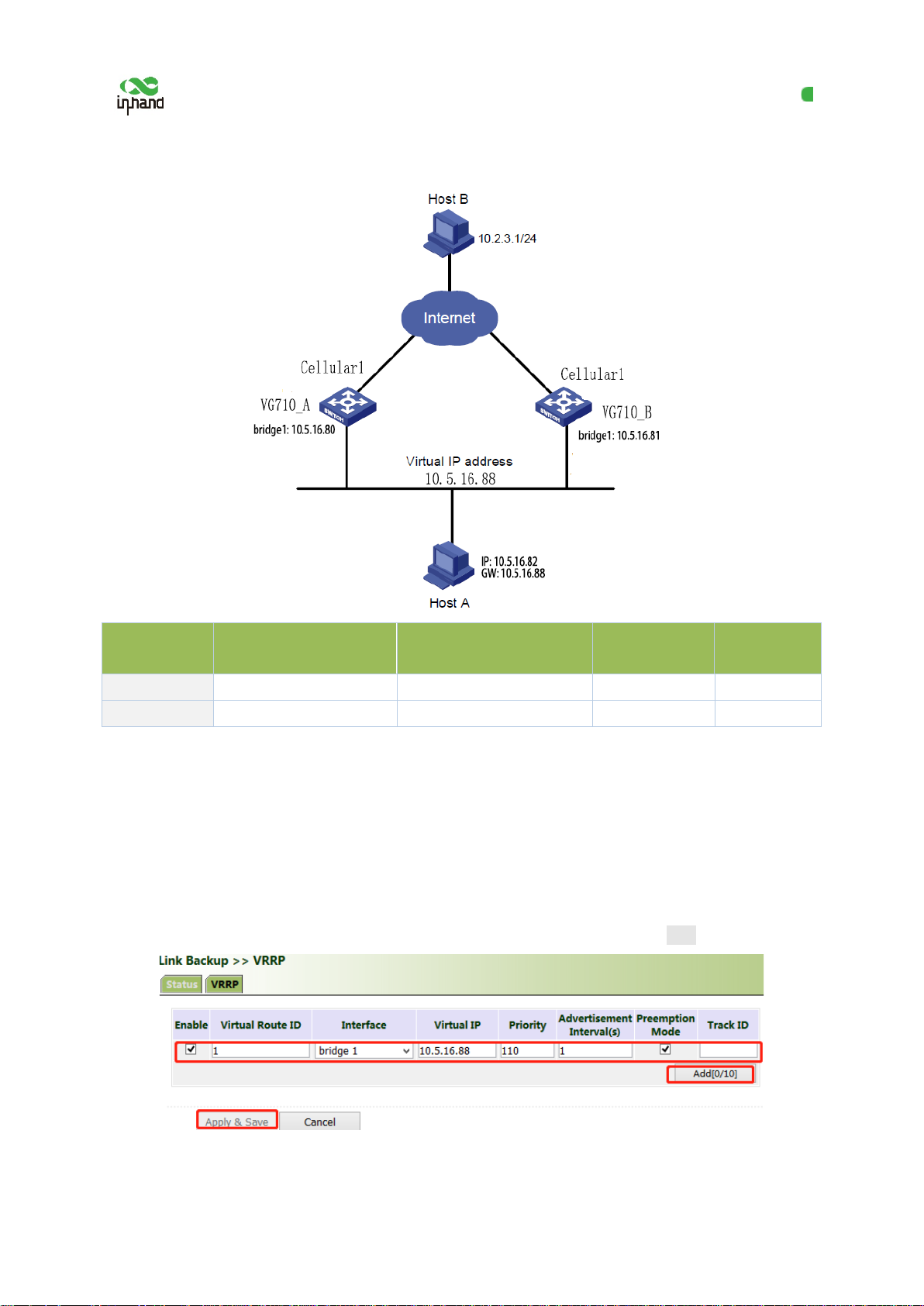
1. Networking requirement
Host A uses the VRRP backup group comprisin g gateway A and gateway B as its default gateway to
access host B on the Internet.
Information of the VRRP backup group:
● The backup group ID is 1.
● The IP address of the virtual gateway of the backup group is 10.5.16.88.
● Gateway A acts as the master gateway.
● Gateway A acts as a backup gateway that can be preempted.
47
Page 53
InHand VG710 InVehicle Gateway User Manual
connected to host A
connected to host A
2. Networking diagram
Gateway
Ethernet port
IP address of the port
Priority Work mode
VG710_A bridge 1 10.5.16.80 110 Preemption
VG710_B bridge 1 10.5.16.81 100 Preemption
Method for settings when VG710_A acts as the master gateway and VG710_B as a backup
gateway:
1. Configure VG710_A.
Click "Link Backup >> VRRP", set "Virtual Route ID" as required, select the gateway interface of
VG710_A, enter the virtual IP address, set the interface priority to 110, and click Add.
In the navigation tree, click "Link Backup >> VRRP >> Status" and view the VRRP status.
48
Page 54
InHand VG710 InVehicle Gateway User Manual
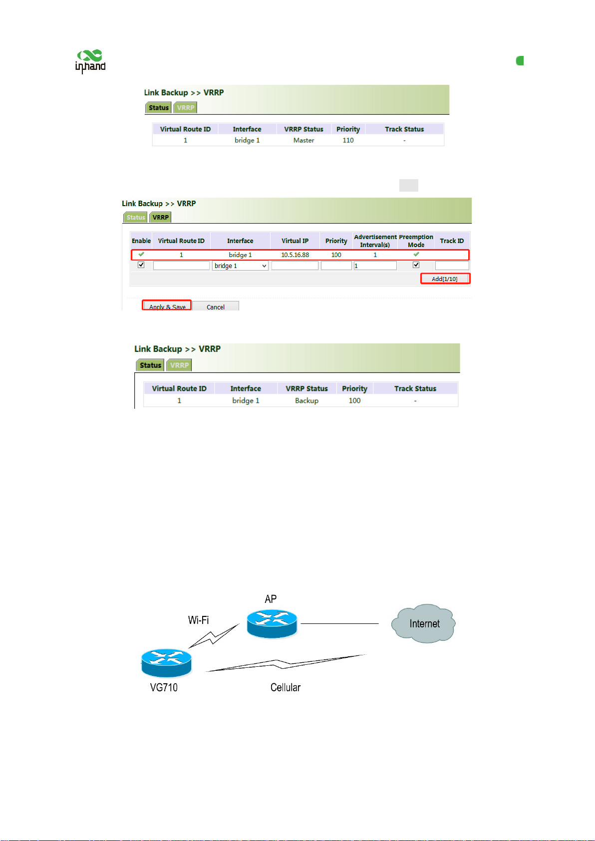
2. Configure VG710_B.
Click "Link Backup >> VRRP", set the interface priority to 100, and click Add.
In the navigation tree, click "Link Backup >> VRRP >> Status" and view the VRRP status.
Under normal circumstances, VG710_A performs gateway functions. When VG710_A is shut down
or fails, VG710_B performs gateway functions. The preemption mode is intended to enable VG710_A
to continue to act as the master gateway after it recovers.
5.7.4 Interface Backup
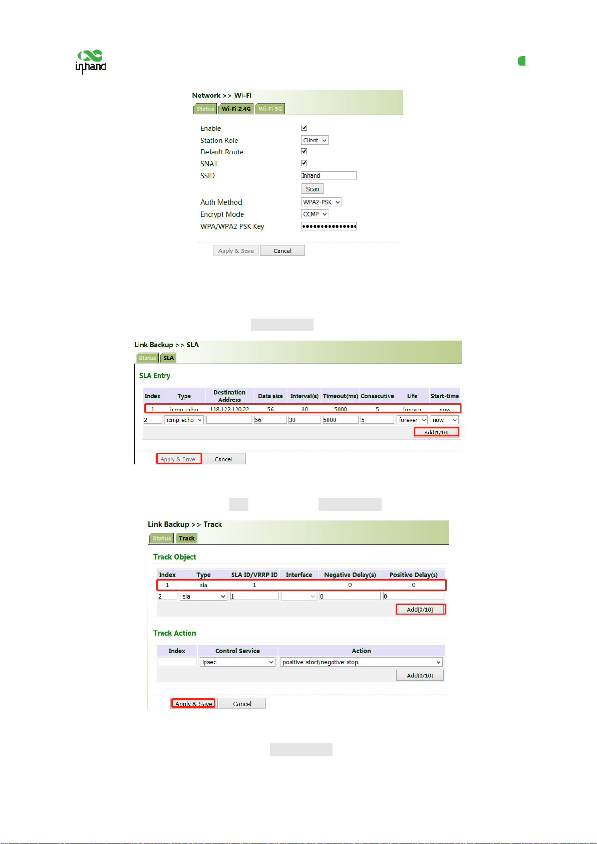
Scenario: VG710 accesses the Intern et via Wi-Fi, and an interface backup is created to enable VG710
to access the Internet through dial-up upon Wi-Fi failure. The topology is shown below.
Method for creating an interface backup for the gateway:
1. Enable VG710 to access the Internet via Wi-Fi.
49
Page 55
InHand VG710 InVehicle Gateway User Manual
2. Click "Link Backup >> SLA >> SLA >> Add" to add an ICMP detection entry. Set th e I P address
to the host address that can be detected over ICMP on the public or private network, for example, the
public IP address 118.122.120.22. Click Apply & Save.
3. Click "Link Backup >> Track >> Track >> Add" to add a track entry. Select "sla" for "Typ e" and
"dot11radio1" for "Interface", click Add, and then click Apply & Save.
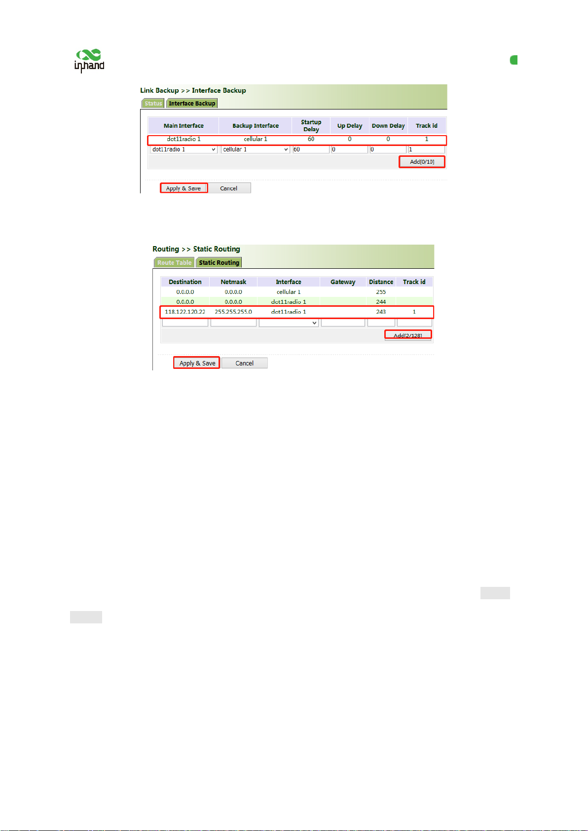
4. Click "Link Backup >> Interface Back up >> Add", select "dot11radio1" for "Main Interface" and
"cellular1" for "Backup Interface", and click Apply & Save.
50
Page 56
InHand VG710 InVehicle Gateway User Manual
5. Click "Routing >> Static Routing >> Add" and add two routes for network access through the
"dot11radio1" and "cellular1" interfaces. A smaller value of "Distance" indi cates a higher priority.
6. Trigger a Wi-Fi failure. According to the preset link det ection policy, VG710 accesses the Internet
through dial-up via the cellular port, and when Wi-Fi recovers, immediately switches to Wi-Fi for
Internet access.
5.8 Wizards
The "Wizards" module incorporates some common communication parameters, simplifying the
operations.
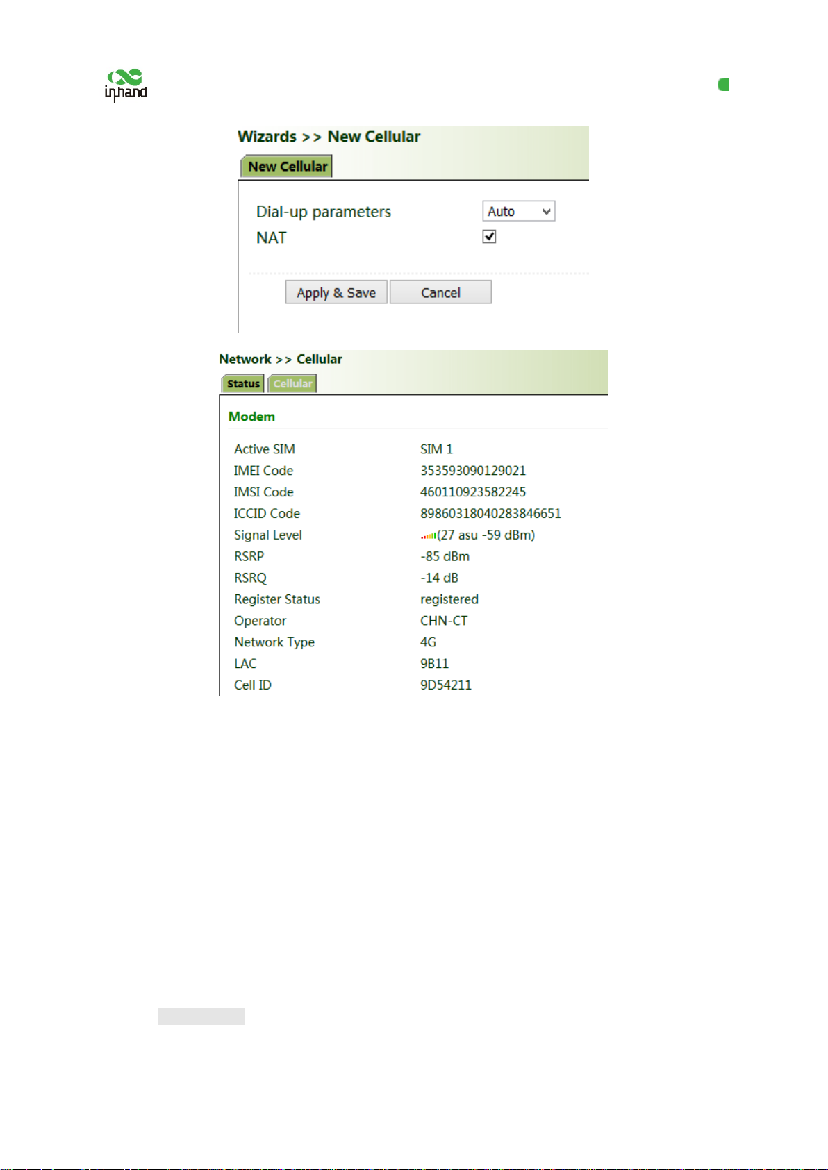
5.8.1 New Cellular
After a common network interface card (NIC) is i nserted, click "Wizards >> New Cellular >> Apply
& Save" and access the status page to view the network connection status of the device. The device is
connected to the network.
51
Page 57
InHand VG710 InVehicle Gateway User Manual
5.8.2 New IPsec Tunnel
A dedicated virtual tunnel is established between the gateway and other devices or cloud platforms on
the network.
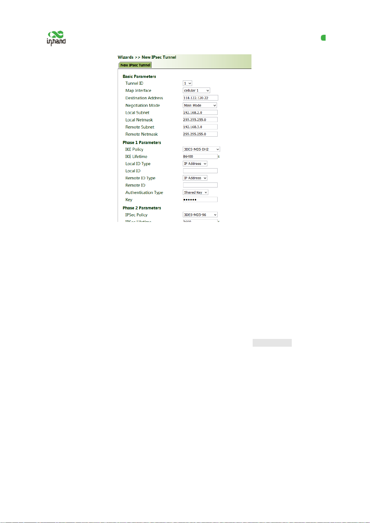
Method for establishing an IPsec tunnel for the gateway:
Click "Wizards >> New IPsec Tunnel", set " Map Interface" to an interface ("bridg e": bridge interface;
"cellular": dialup interface; "dot11radio": Wi-Fi interface) for which you want to establish a tu nnel,
enter the peer IP address for "Destination Address", and enter the subnet IP addresses and masks at
both ends of the tunnel. In Phase 1, enter the IDs at both ends of the tunnel and the connection key,
and click Apply & Save.
52
Page 58
InHand VG710 InVehicle Gateway User Manual
5.8.3 IPsec Experts' Configuration
This function is available only for specific users. To activate this function, contact the technical
support personnel.
5.8.4 New L2TPv2 Tunnel
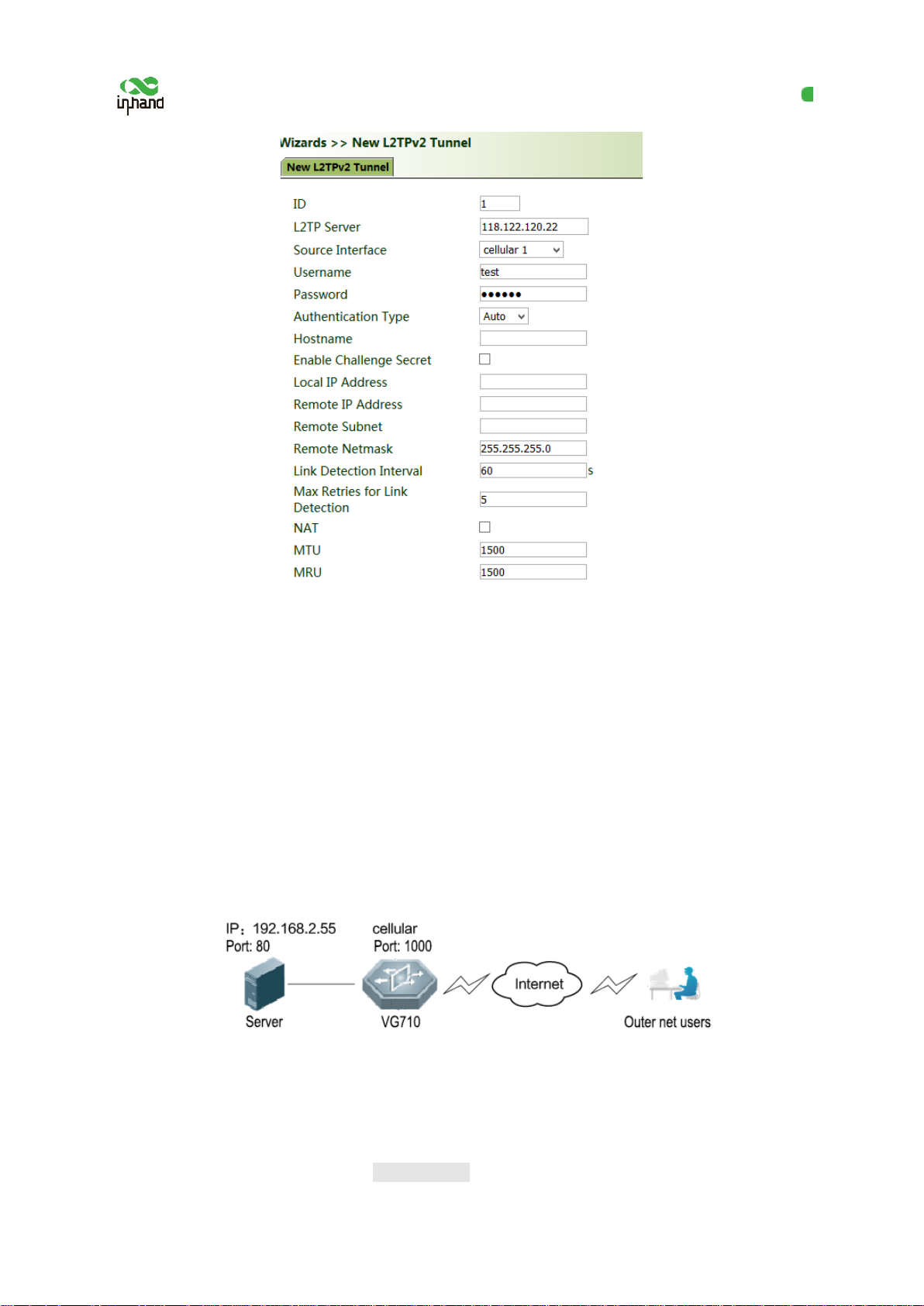
Method for creating an L2TPv2 tunnel for the gateway:
Set the parameters of the L2TP server and the local/remote addresses. Click Apply & Save.
53
Page 59
InHand VG710 InVehicle Gateway User Manual
5.8.5 New Port Mapping
Port mapping is to map a port of a host on the intranet to a port of a host on the extranet to provide
corresponding services. When a user ac cesses the port on the extranet, the server aut omatically maps
the request to the internal machine on the corresponding LAN.
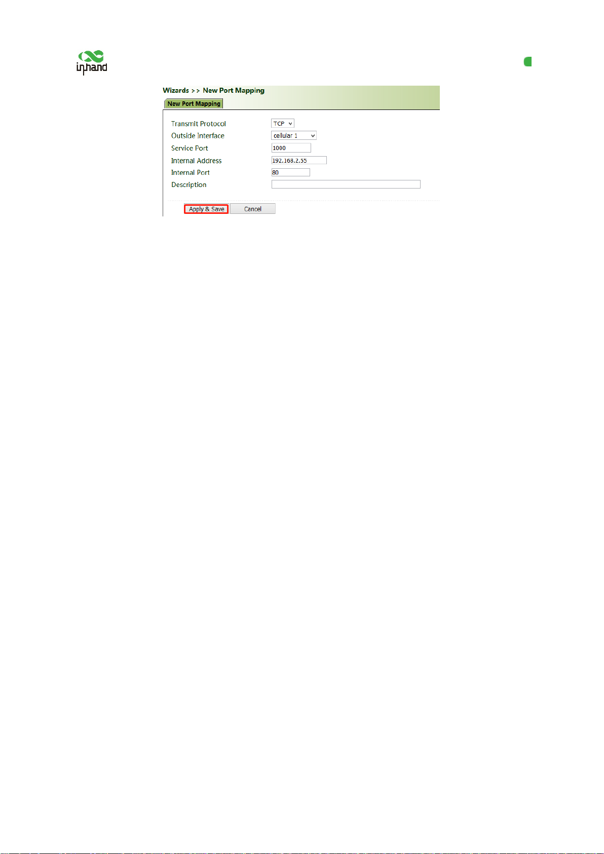
Scenario: Users on the extranet cannot directly access a web server on the intran et. In this case, a port
mapping can be created on the gateway so that the gateway automatically transfers the data to port 80
of the web server on the intranet when a user o n the extranet accesses port 1000 via the cellu lar
interface of the gateway.
Method for creating a port mapping for the gateway:
Click Wizards >> New Port Mapping". Enter the gateway interface for "Outside Interface", gateway
port for "Service Port", IP address of the internal host for "Internal Address", and port ID of the
internal host for "Internal Port". Click Apply & Save.
54
Page 60
InHand VG710 InVehicle Gateway User Manual
55
Page 61

InHand VG710 InVehicle Gateway User Manual
6 APP Management
This function is to be improved.
56
Page 62
InHand VG710 InVehicle Gateway User Manual
7 Connecting the Gateway to a Cloud Platform
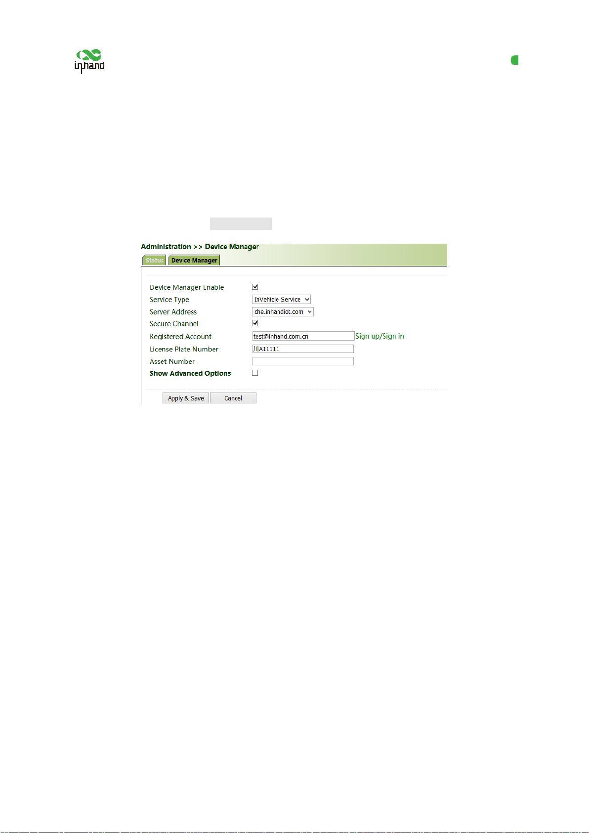
1. Click "Administration >> Device Man ager >> Device Manager", check "Device Manager Enable",
select the server address of the cloud platform, enter the registered account and license plate number
of the cloud platform, and click Apply & Save.
2. Click "Status". "Connected" indicates that the gateway is successfully connected to the cloud
platform.
57
Page 63
InHand VG710 InVehicle Gateway User Manual
RS-485 I/O RS-232
8 Industrial Ports (Serial Ports)
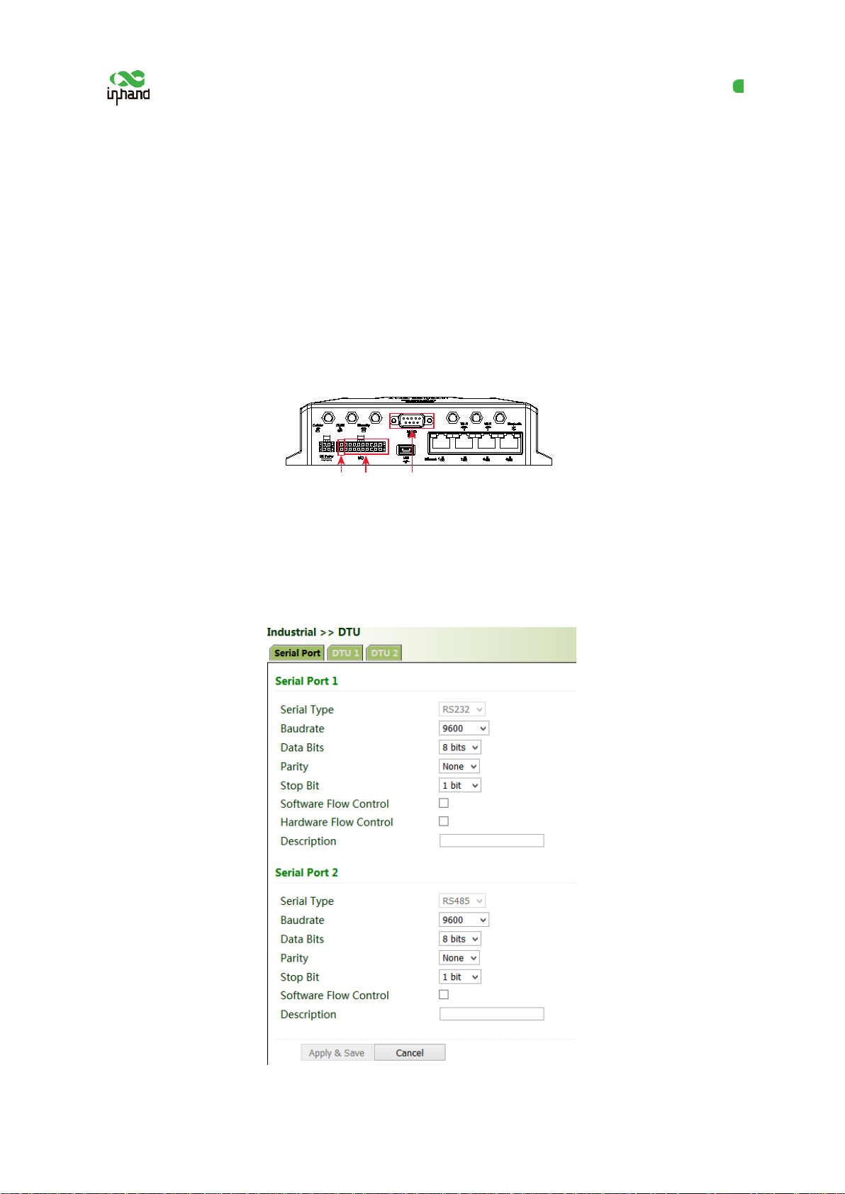
The industrial ports of VG710 include RS232 serial ports, RS485 serial ports, and IO ports.
8.1 DTU
RS232 provides full-serial communication, enabling hardware-based traffic control.
RS485 provides half-duplex communication, enabling remote transmission of serial communication
data.
Method for setting web pages when the gateway is used as a DTU:
1. Enable DTU 1 (RS232) or DTU 2 (RS-485).
2. Set the connection parameters of the gateway interface and industrial device. Communication is
available only when the parameters at both ends of the network link are consistent.
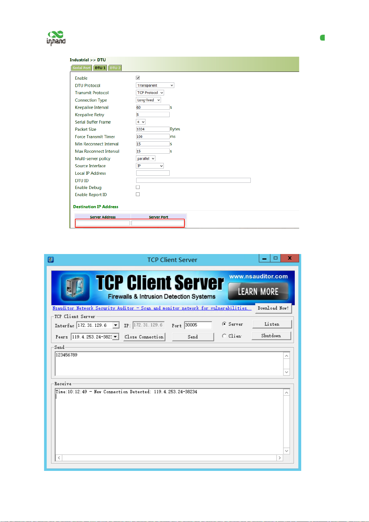
3. Set the IP address and transmit protocol (TCP or UDP) of the server.
58
Page 64
InHand VG710 InVehicle Gateway User Manual
4. Check that the gateway-connected PC and the server exchange data through DTU.
59
Page 65
InHand VG710 InVehicle Gateway User Manual
8.2 IO Ports
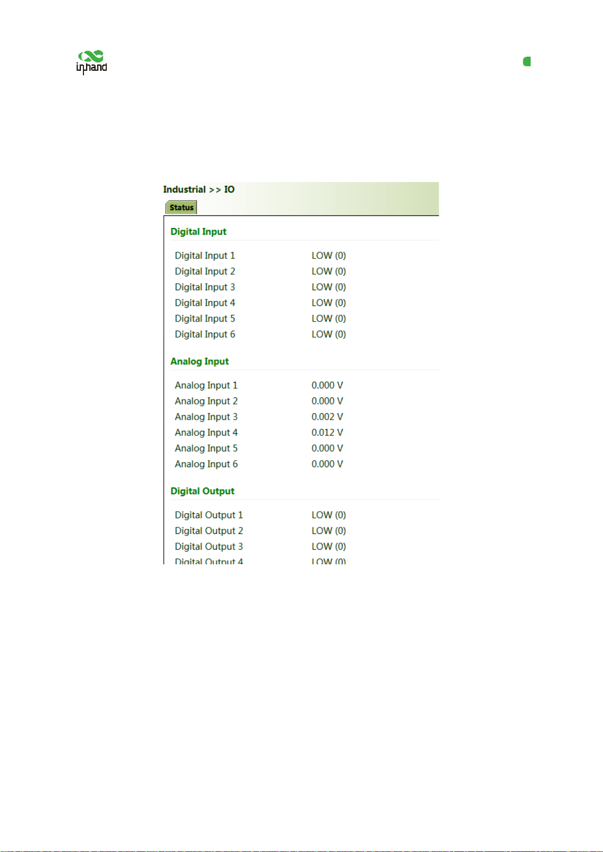
IO ports provide six analog inputs, six digital inputs, and four digital outputs. The analog and digital
inputs share the ports. The digital parameters correspond to two states: HIGH (1) and LOW (0).
60
Page 66
InHand VG710 InVehicle Gateway User Manual
9 System Management
9.1 System
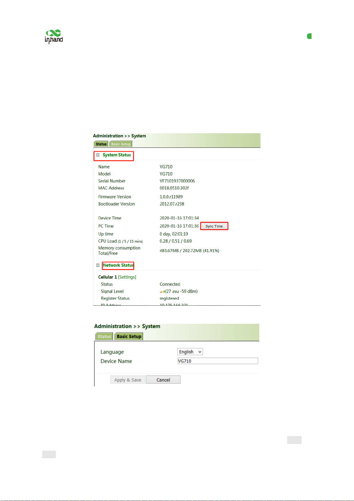
Click "Administration >> System >> Status" and view the current system and n etwork status of the
device.
Click "Basic Setup" and modify the sy ste m language and device name.
9.2 System Time
To ensure the coordination between the d evice and other devices, set the system time accurately.
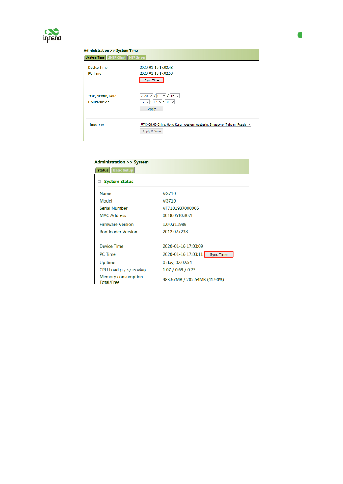
Manual time synchronization: Click "Administration >> System Time >> System Ti me >> Sync
Time" to ensure consistency between the gateway time and host time.
61
Page 67
InHand VG710 InVehicle Gateway User Manual
Alternatively, click "Administration >> System >> Status" to synchronize the time.
Automatic time synchronization: Click "Administration >> System Time >> SNTP Client or NTP
Server" and check "Enable" to synchronize the time between the gateway and the SNTP or NTP
server.
After NTP is enabled, the gateway can synchronize time for all devices on the network.
62
Page 68
InHand VG710 InVehicle Gateway User Manual
9.3 Management Services
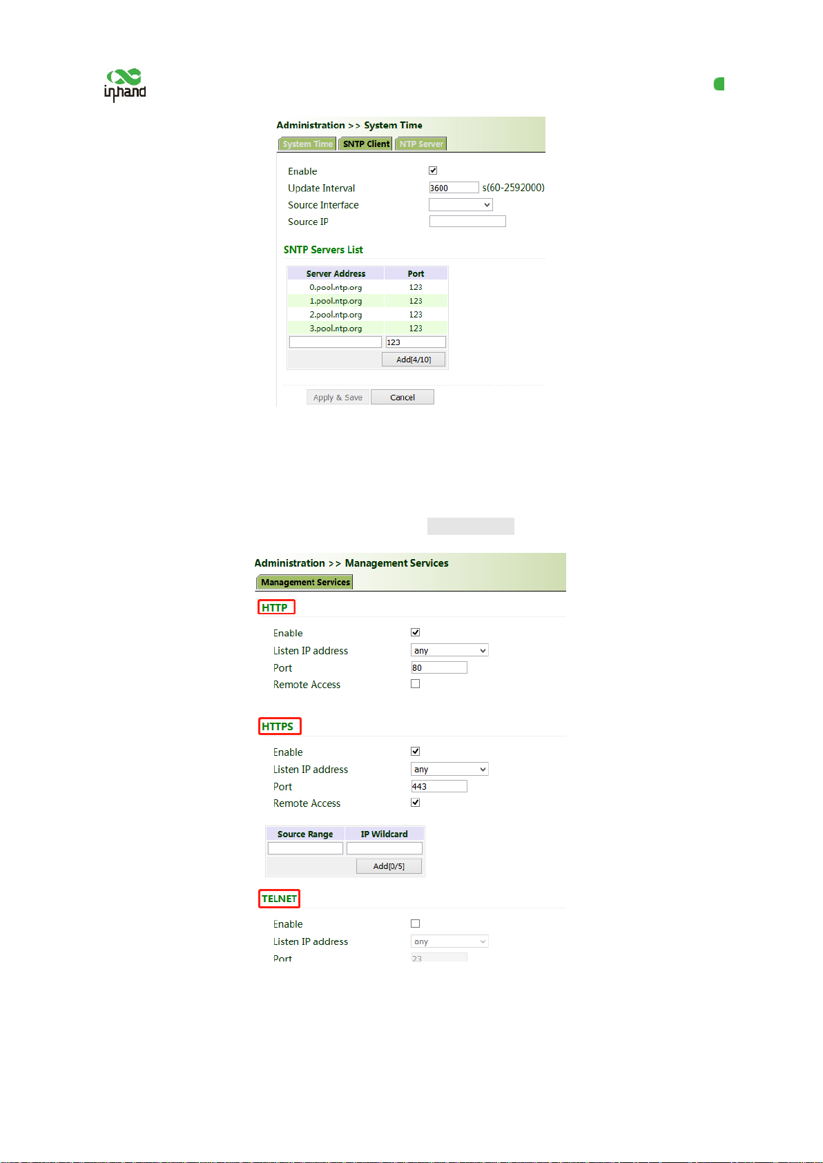
When the gateway requires the HTTP, HTTPS, TELNET, and SSH functions, click "Administration >>
Management Services", enable the serv ices, and click Apply & Save.
63
Page 69

InHand VG710 InVehicle Gateway User Manual
9.4 User Management
Click "Administration >> User Management" and create users, modify passwords, or delete users on
the user management page.
Superuser and common user:
● Super user: By default, only one superuser is automatically created by the system, with the
user name of adm and the default password of 123456. It has full access rights for the
gateway.
● Common user: A common user is created by the superuser. I t can view or modify gateway
configurations.
Note: You cannot delete the superuser (
password.
) or modify its user name, but can modify its
adm
9.5 AAA
Authentication, authorization, an d accounting (AAA) is a security management mechan ism for access
control in network security, which provides three security services: authentication, authorization, and
accounting.
It provides modular methods for the following services:
● Authentication: Verify whether a user has the right for n etw or k acc ess .
● Authorization: Authorize a user to use specific services.
● Accounting: Record network resource usage of a user.
64
Page 70
InHand VG710 InVehicle Gateway User Manual
You can use only one or two of the security services provided by AAA. For example, if a company
only expects to authenticate employees when they access specific resources, the network administrator
only needs to configure the authentication server. However, if the company expects to record the
network usage of employees, the accounting server must be configured.
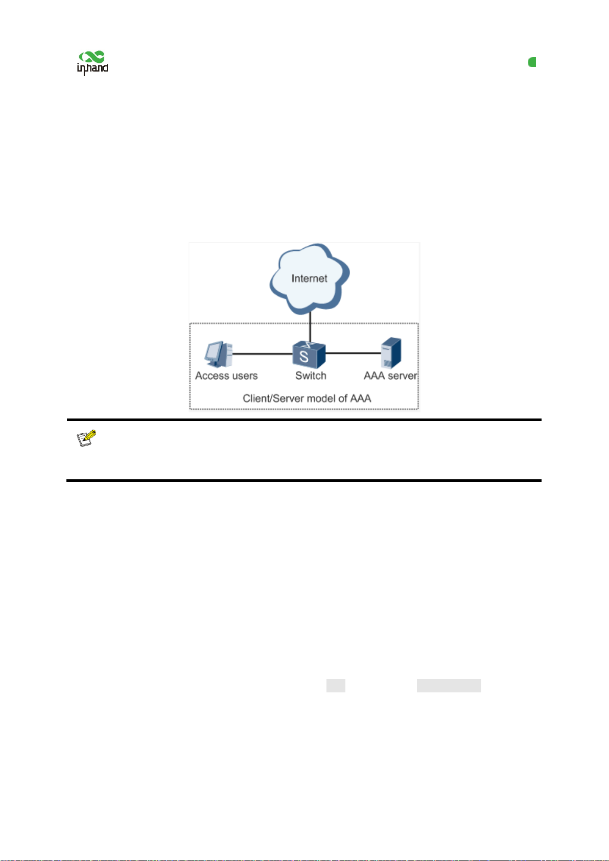
AAA usually works in the client/server structure, which is highly scalable and is convenient for
centralized management of user information, as shown in the figure below.
Note:
indicates the local user name and password of the gateway.
Radius, Tacacs+
, and
indicate authentication and authorization servers.
LDAP
Local
9.5.1 Radius
The Remote Authentication Dial In Use r Service (Radius) is a distributed information exchange
protocol based on the client/server structure. It protects the network from unauthorized access, and is
usually used in various network environments that require high security and allow remote user access.
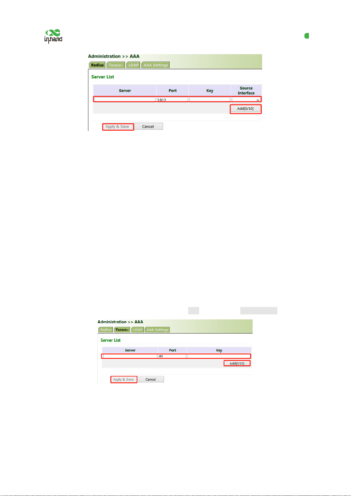
Method for enabling the Radius server for the gateway:
Click "Administration >> AAA >> Radius" . In "Server List", enter the server address (domain
name/IP address), port ID, and authentication key, click Add, and then click Apply & Save.
65
Page 71
InHand VG710 InVehicle Gateway User Manual
9.5.2 Tacacs+
The Terminal Access Controller Access Control System + (Tacacs+) protocol is similar to the Radius
protocol. It uses the client/server mode f or communication between the network access server (NAS)
and the Tacacs+ server. However, Tacacs+ wo r ks based on TCP, and Radius works based on UDP.
The Tacacs+ protocol is mainly used for AAA of end users and Point-to-Point Protocol (PPP) and
virtual private dial-up network (VPDN) access users. Its typical application is to authenticate,
authorize, and perform accounting for an end user who needs to log in to the device for operations. As
a Tacacs+ client, the device sends the user name and password to the Tacacs+ server for v er ification.
After authentication and authorization, the user can log in to the device for operations.
Method for enabling the Tacacs+ server for the gateway:
Click "Administration >> AAA >> Tacacs+". In "Server List", enter the server address (domain
name/IP address), port ID, and authentication key, click Add, and then click Apply & Save.
9.5.3 LDAP
The main advantage of the Lightweight Directory Access Protocol (LDAP) lies in its quick response
to users' search operations. For example, massive user authentication op er ations may be performed
concurrently. If a database is used, because t he database is divided into various tables, to meet this
66
Page 72
InHand VG710 InVehicle Gateway User Manual
simple authentication requirement, the database must be searched each time, along with synthesis and
filtering. This results in low efficiency. LDAP is equivalent to one table, and requires only the user
name and password, with some other parameters, which is quite simple. It can meet the authentication
requirement regarding the efficiency and structure.
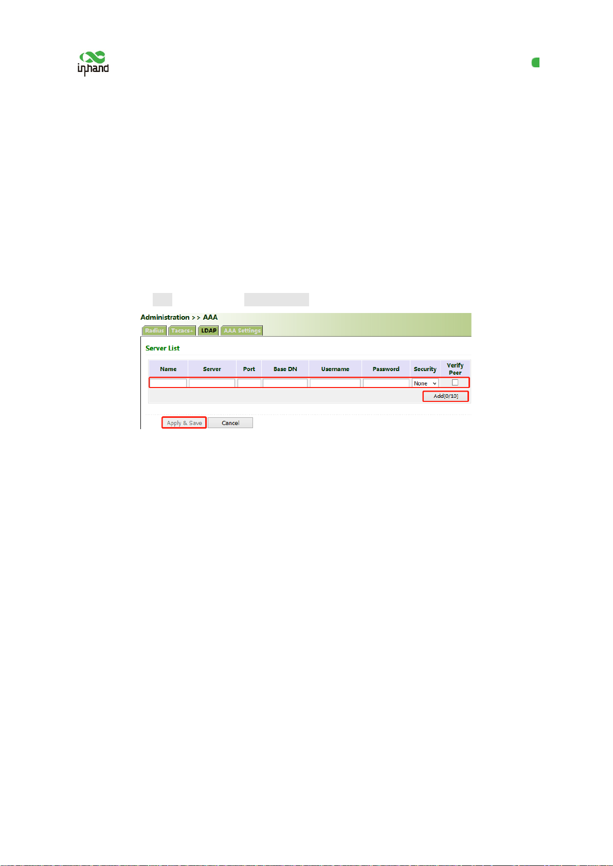
Method for enabling the LDAP server for the g ateway:
Click "Administration >> AAA >> LDAP". In "Server List", enter any name for "Name", enter the
server address (domain name/IP address) an d port ID, and enter the base DN obtained from the server.
Set the user name and password for accessin g the server. Select "None", "SSL", or "Star tTLS" for
"Security". Click Add, and then click Apply & Save.
9.5.4 AAA Authentication
AAA authentication methods:
● No authentication (none): No validity check is performed. Generally, this method is not used.
● Local authentication (local): User information is configured on the NAS. Local authentication is
fast, which can reduce the operational costs, but the information storage amount is limited by
hardware.
● Remote authentication: User information is configured on the authentication server. Remote
authentication is supported over Radius, Tacacs+, and LDAP.
AAA authorization methods:
● No authorization (none): No authorization is performed for users.
● Local authorization (local): Authorization is perf or med based on the properties conf igured by the
NAS for the local account.
● Tacacs+ authorization: Users are authorized by the Tacacs+ server.
● Authorization after successful Radius authentication: Authorization is bound to authentication,
67
Page 73
InHand VG710 InVehicle Gateway User Manual
and cannot be performed independently over Radius.
● LDAP authorization
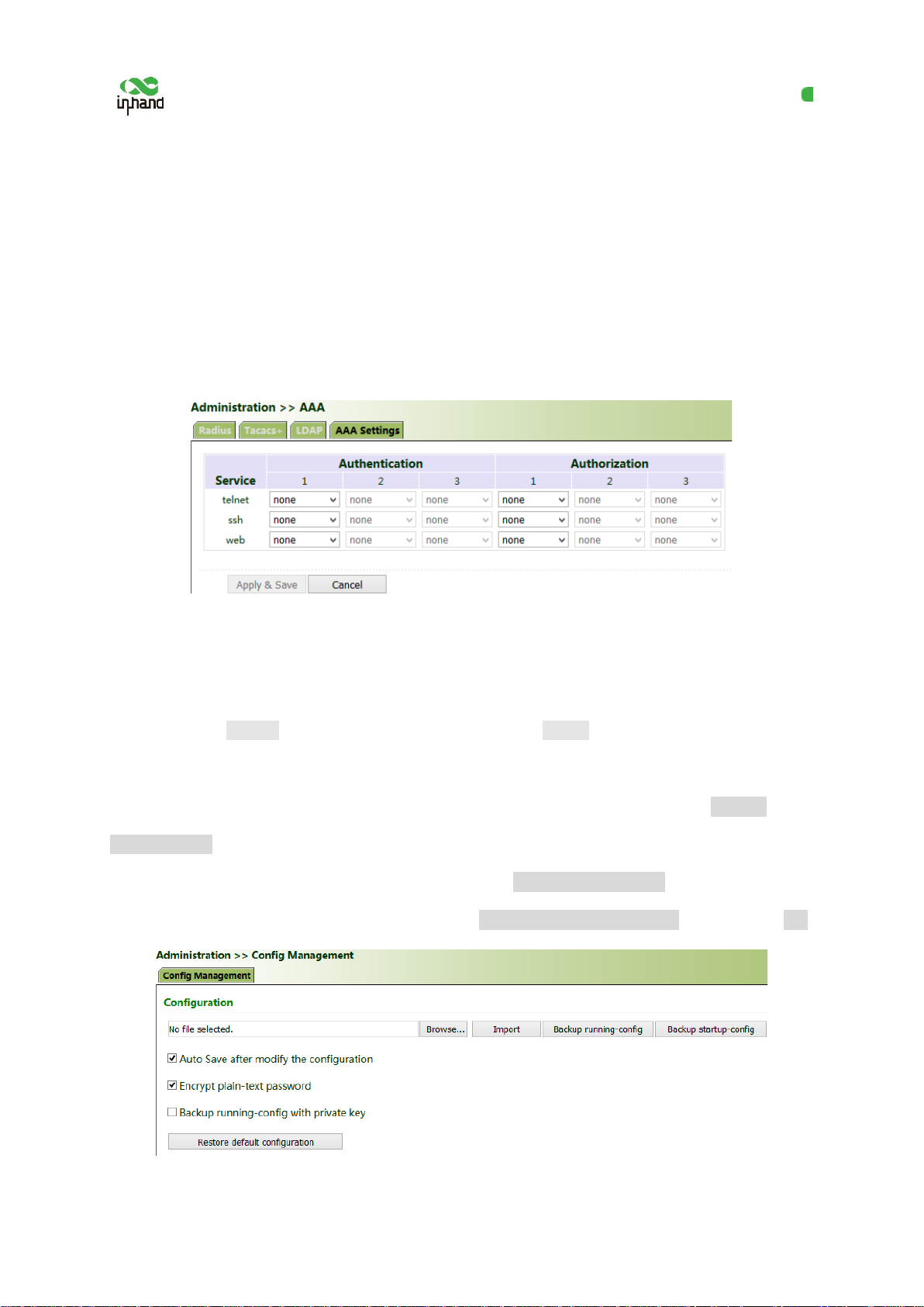
Method for enabling authentication and authorization for the gateway:
Click "Administration >> AAA >> AAA Settings". 1, 2, and 3 are corresponding to Radius, Tacacs,
ad LDAP respectively. Authentication entries 1, 2, and 3 must be corresponding to authorization
entries 1, 2, and 3 respectively. When all of radius, tacacs+, and local are set, the priority sequence is
as follows: 1 > 2 > 3.
9.6 Configuration Management
Method for importing configurations: Click "Administration >> Config Management >> Config
Management >> Browse", select a configuration file, and click Import to import the configuration file
to the gateway.
Method for backing up current running configurations to the PC (common): Click Backup
running-config.
Method for backing up the startup file to the PC: Click Backup startup-config.
Method for restoring default configurations: Click Restore default configuration and then click OK.
68
Page 74
InHand VG710 InVehicle Gateway User Manual
9.7 SNMP
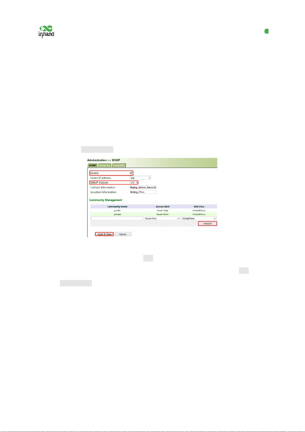
9.7.1 SNMP
Currently, the SNMP Agent of VG710 supports SNMPv1, SNMPv2c, and SNMPv3.
● SNMPv1 and SNMPv2c use community names for authentication.
● SNMPv 3 uses user names and passwords for auth entication.
Method for enabling SNMP for VG710:
Click "Administration >> SNMP >> SNMP", check "Enable", select "v1c" for "v2c" for "SNMP
Version", and click Apply & Save.
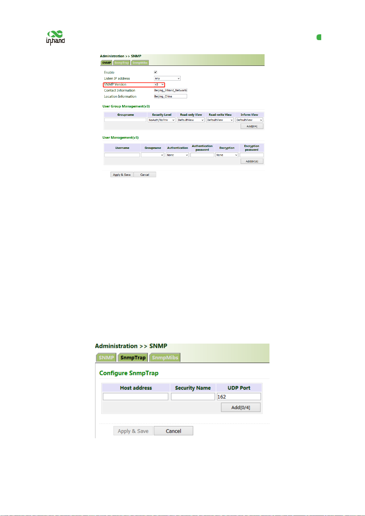
If v3c is selected, the corresponding user and user group need to be configured. Enter any name for
"Groupname", select a security level, and click Add. Enter any name for "Username", select the new
group name for "Groupname", set "Authentication" and "Authentication password", click Add, and
then click Apply & Save.
69
Page 75
InHand VG710 InVehicle Gateway User Manual
9.7.2 SnmpTrap (Alarm)
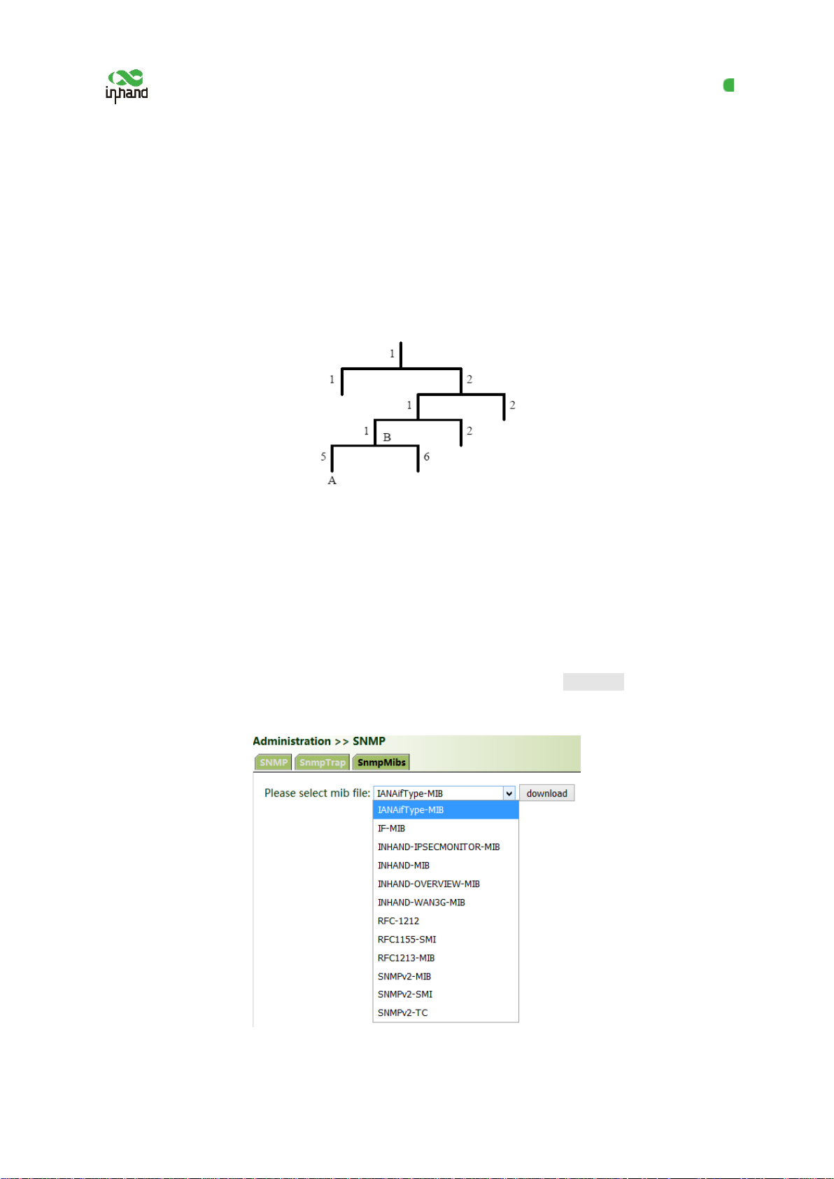
The SNMP trap is a type of entrance. When this entrance is reached, the SNMP managed dev ices
actively notify the NMS, instead of waiting for the polling of NMS. On an SNMP-enabled network,
the agents on managed devices can report errors to the NMS anytime, without the need of waiting for
the polling of NMS. The errors are reported to the NMS through traps.
Method for enabling SnmpTrap for the gateway:
Click "Administration >> NMP >> SnmpTrap". E nter the IP address of the NMS. Enter the
corresponding group name when v1c or v2c is selected, or the corresponding user name when v3c is
selected, ensuring that the name consists of 1–32 characters. By default, the UDP port I D r anges from
1 to 65535.
70
Page 76
InHand VG710 InVehicle Gateway User Manual
9.7.3 SnmpMibs
In SNMP messages, management variables are used to describe the managed object s on the device. To
uniquely identify the managed objects on the device, SNMP uses a hierarchical naming scheme to
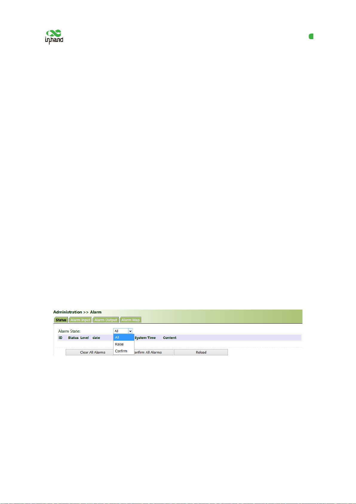
identify the managed objects The entire hierarchical structure is like a tree. The nodes of the tree
represent the managed objects, as shown in the figure below. Each node can be uniquely identified by
a path starting from the root.
The management information base (MIB) is used to describe the hierarchical structure of the tree. It is
a set of standard variable definitions for the monitored network device. In the above figure, managed
object B can be uniquely determined based on a string of numbers {1.2.1.1}, which form the object
identifier (OID) of the managed object.
Method for downloading a SnmpMibs file to the PC via the gateway:
Click "Administration >> SNMP >> SnmpMibs", select a folder, and click download to download it to
the PC. Find the folder on the PC and import it to the NMS.
71
Page 77
InHand VG710 InVehicle Gateway User Manual
9.8 Alarm
The alarm function enables users to ident ify gateway abnormalities in time. When an abnormality
occurs, the gateway reports an alarm. Yo u can select system-defined abnormalities and choose an
appropriate notification way to obtain the abnormality information. All alarms ar e r ecorded in alarm
logs so that users can identify abnormalities and perform troubleshooting in time.
Alarm states:
● Raise: indicates that the alarm has been generated but not been confirmed.
● Confirm: indicates that the alarm cannot be solved currently.
● All: indicates all generated alarms.
Alarm levels:
● EMERG: Th e device undergoes a serious error that causes a system reboot.
● CRIT: The device undergoes an unrecoverable error.
● WARN: T he device undergoes an error that affects system functions.
● NOTICE: The device undergoes an error that affect s system performance.
● INFO: A no rmal event occurs.
(1) Status: Click "Administration >> Alarm >> Status" and view all alarms generated in th e system
since power-on.
(2) Alarm Input: Select an alarm type as requ ired. When this item is abnormal, an alarm is generated.
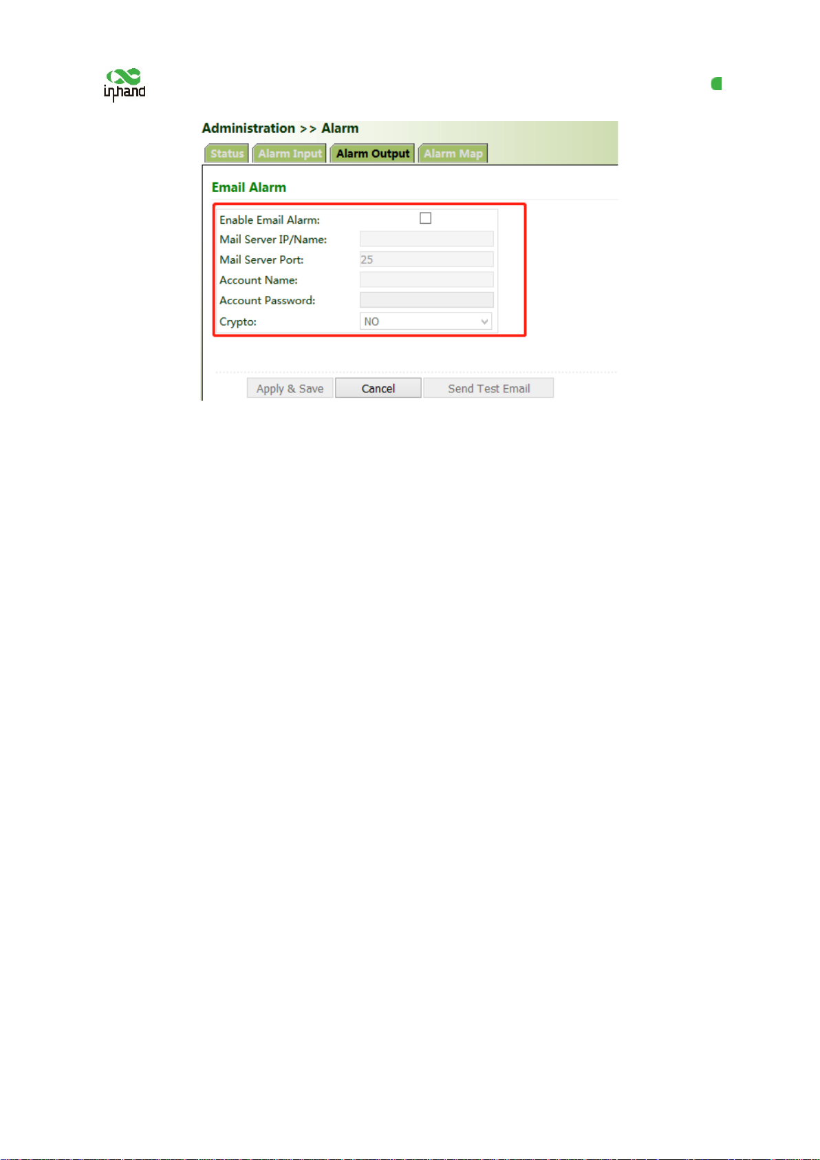
(3) Alarm Output: When an alarm is generated, the system automatically sends the alarm content to
the destination email address via an email. This function is not available for common users. Set the
sender mail address in "Email Alarm" an d the receiver mail address in "Mail Address". " Mail Server
IP/Name" can be found on the browser (for example, enter "smtp.exmail.qq.com" if you use a Tencent
Enterprise mailbox.)
72
Page 78
InHand VG710 InVehicle Gateway User Manual
(4) Alarm Map: Alarms can be received in two ways: command line interface (CLI) (console
interface) and Email. Some devices support SMS alarms. To enable email-based mapping, enable and
set the email address on the "Alarm Output" page.
9.9 System Logs
Method for viewing system logs:
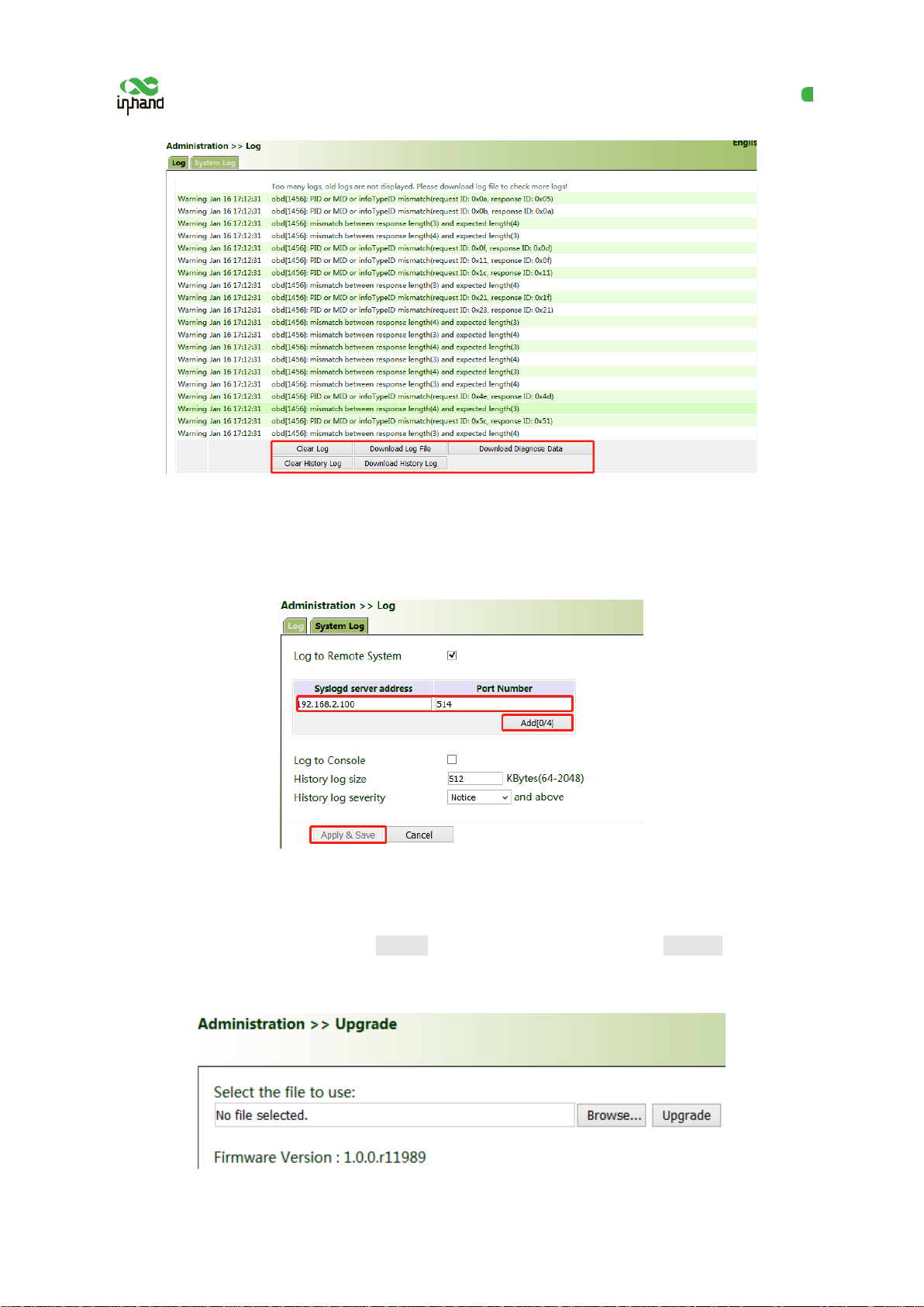
Click "Administration >> System Log" to view system logs.
This page also provides the following operations: "Clear Log", "Download Log File", "Download
Diagnose Data", "Clear History Log", and "Download History Log". History log s are those stored for
extended time as specified on the "System Log" page.
The diagnose data file is encrypted, because the gateway configuration information is downloaded
together with the diagnose data. You need to decrypt the file with the decryption tool provided by
InHand.
73
Page 79
InHand VG710 InVehicle Gateway User Manual
The storage capacity of the gateway is limited ( 512 KB by default). To save all the logs, you need to
use a remote log server (for example, Kiwi Syslog Daemon). Set the address and por t of the log server
on the web page. The gateway uploads all the system logs to the remote log server.
9.10 System Upgrade
Click "Administration >> Upgrade >> Browse", select an upgrade file, and click Upgrade. Restart the
system after the upgrade is completed.
74
Page 80
InHand VG710 InVehicle Gateway User Manual
Note:
During the software upgrade, do not perform any operation on the web page; otherwise, the software
upgrade may be interrupted.
9.11 System Reboot
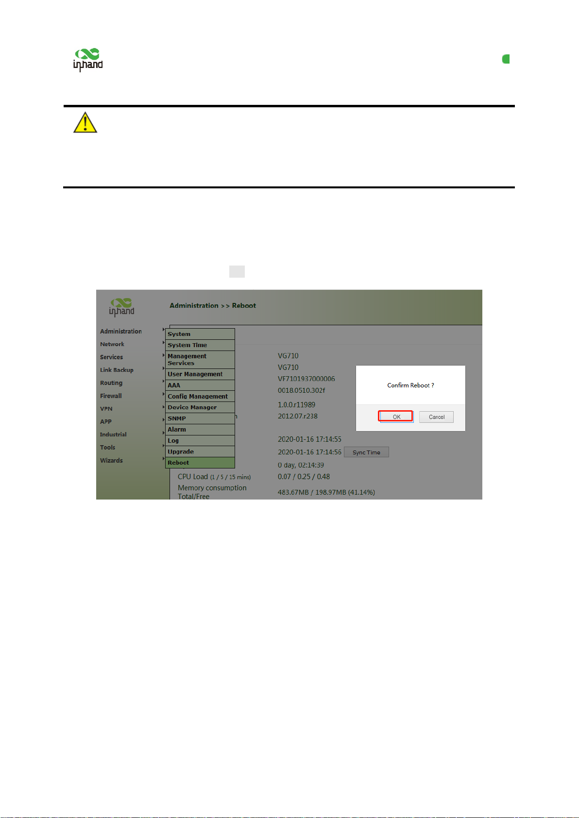
Click "Administration >> Reboot >> OK to reb oot the system.
75
Page 81
InHand VG710 InVehicle Gateway User Manual
10 Diagnostic Tools
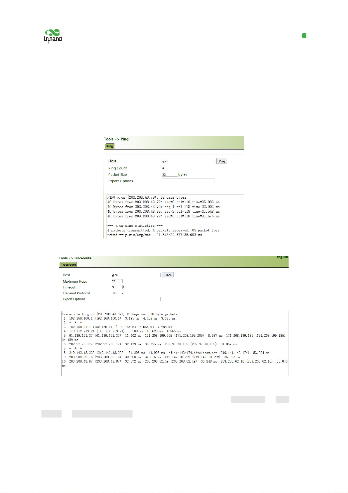
Diagnostic tools are used to detect the network connection of the gateway: Ping, Traceroute,
Tcpdump, and Link Speed Test.
Ping: It is used to detect the external network connection of the device. Enter any common website in
China for "Host" and click "Ping". If data transmission occurs, the network is connected properly.
Traceroute: Enter the IP address of the peer host and click "Trace" to detect the route connection.
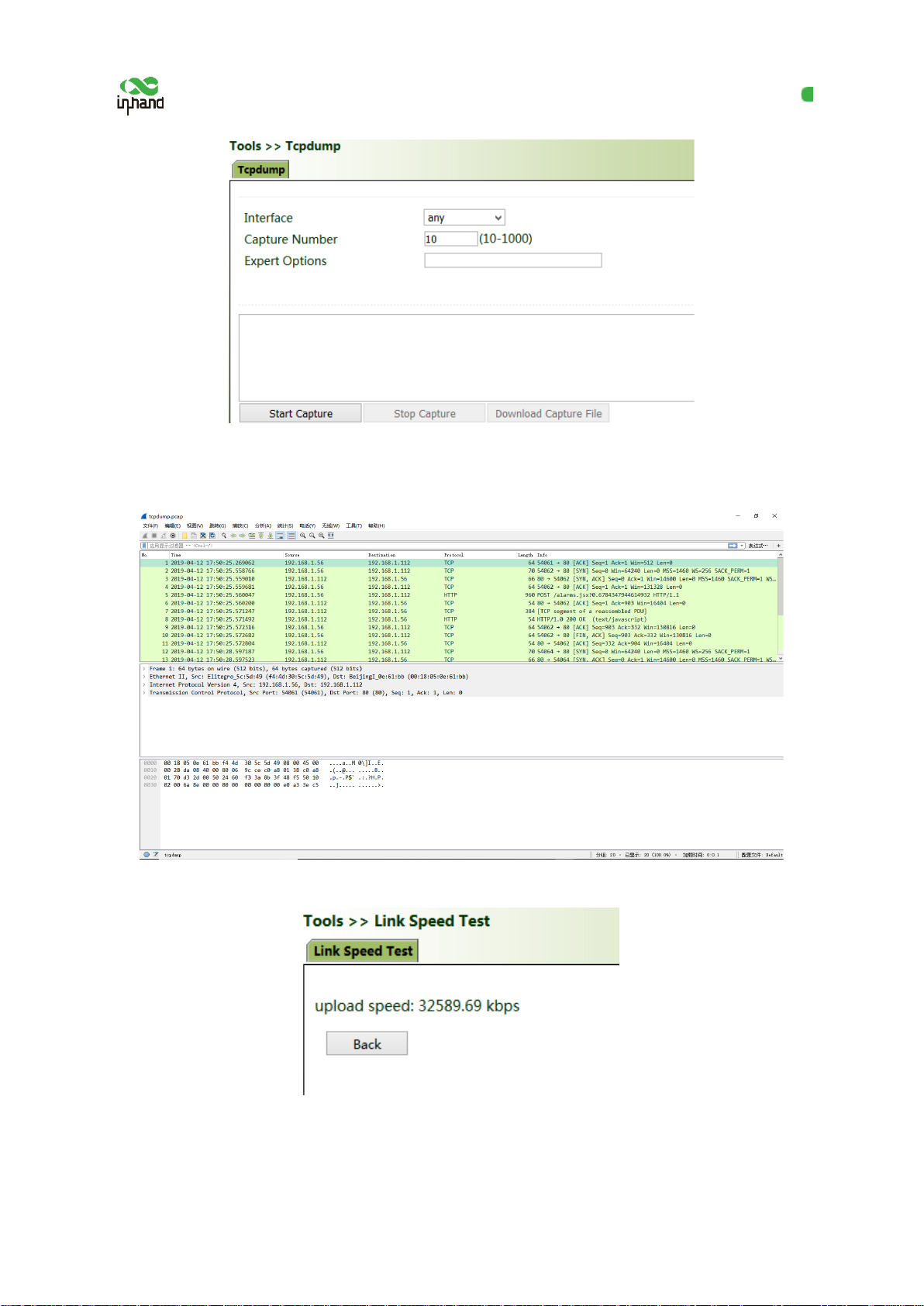
Tcpdump:
Select an interface ("any" or "bridge1 "), set "Capture Number", and click Start Capture >> Stop
Capture >> Download Capture File.
76
Page 82
InHand VG710 InVehicle Gateway User Manual
Download wireshark from the browser to open the downloaded file and analyze the messages to
understand the network connection of the interface.
Link Speed Test: Upload and download files to test the link speed.
77
 Loading...