

Page 1
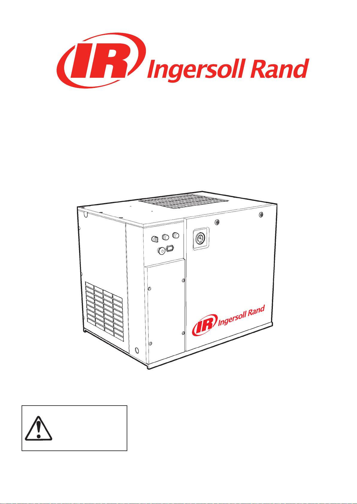
SSR UP5-4, UP5-5.5, UP5-7.5, UP5-11c
50 Hz
SSR UP6-5, UP6-7.5, UP6-10, UP6-15c
60 Hz
OPERATION AND MAINTENANCE MANUAL
This manual contains
important safety information
and must be made available
to personnel who operate
and maintain this machine.
Refer all communications to the nearest Ingersoll Rand Full Service Distributor.
C.C.N. : 80445273
REV. : A
DATE :
OCTOBER 2008
Page 2
AIR COMPRESSOR GROUP
BONDED WARRANTY & REGISTERED START UP
Warranty
Note that this is Ingersoll Rand standard warranty. Any warranty in force at the time of purchase of the compressor or
negotiated as part of the purchase order may take precedence over this warranty.
Register on-line at http://air.ingersollrand.com
Ingersoll Rand
Industrial Air Solutions
Swan Lane
Hindley Green
Wigan WN2 4EZ
Ingersoll Rand Asia Pacic
C/O Ingersoll Rand South East Asia (Pte) Ltd.
42 Benoi Road
Singapore 629903
Ingersoll Rand
Industrial Air Solutions
P.O. Box 1840
800−D Beaty Street
Davidson, NC 28036
The Company warrants that the equipment manufactured by it and delivered hereunder will be free of defects in material and
workmanship for a period of twelve months from the date of placing the Equipment in operation or eighteen months from the
date of shipment from the factory, whichever shall rst occur. The Purchaser shall be obligated to promptly report any failure to
conform to this warranty, in writing to the Company in said period, whereupon the Company shall, at its option, correct such
nonconformity, by suitable repair to such equipment or, furnish a replacement part F.O.B. point of shipment, provided the
Purchaser has stored, installed, maintained and operated such Equipment in accordance with good industry practices and has
complied with specic recommendations of the Company. Accessories or equipment furnished by the Company, but manufactured by others, shall carry whatever warranty the manufacturers have conveyed to the Company and which can be passed on to
the Purchaser. The Company shall not be liable for any repairs, replacements, or adjustments to the Equipment or any costs of
labor performed by the Purchaser or others without Company‘s prior written approval.
The eects of corrosion, erosion and normal wear and tear are specically excluded. Performance warranties are limited to those
specically stated within the Company‘s proposal. Unless responsibility for meeting such performance warranties are limited to
specied tests, the Company‘s obligation shall be to correct in the manner and for the period of time provided above.
THE COMPANY MAKES NO OTHER WARRANTY OR REPRESENTATION OF ANY KIND WHATSOEVER, EXPRESSED OR IMPLIED,
EXCEPT THAT OF TITLE, AND ALL IMPLIED WARRANTIES OF MERCHANTABILITY AND FITNESS FOR A PARTICULAR PURPOSE, ARE
HEREBY DISCLAIMED.
Correction by the Company of nonconformities whether patent or latent, in the manner and for the period of time provided
above, shall constitute fullment of all liabilities of the Company for such nonconformities whether based on contract, warranty
negligence, indemnity, strict liability or otherwise with respect to or arising out of such Equipment.
The purchaser shall not operate Equipment which is considered to be defective, without rst notifying the Company in writing of
its intention to do so. Any such use of Equipment will be at Purchaser‘s sole risk and liability.
Page 3

Operation and Maintenance Manual Contents
CONTENTS
FOREWORD . . . . . . . . . . . . . . . . . . . . . . . . . . . . . . . . . . . . . . . . . . . . . . . 5
DECALS. . . . . . . . . . . . . . . . . . . . . . . . . . . . . . . . . . . . . . . . . . . . . . . . . . 6
ISO SYMBOLS
. . . . . . . . . . . . . . . . . . . . . . . . . . . . . . . . . . . . . . . . . . . . 6
GRAPHIC FORM AND MEANING OF ISO SYMBOLS . . . . . . . . . . . . . . . . . . . 6
ANSI SYMBOLS . . . . . . . . . . . . . . . . . . . . . . . . . . . . . . . . . . . . . . . . . . . 8
GRAPHIC FORM AND MEANING OF ANSI SYMBOLS . . . . . . . . . . . . . . . . . . 8
SAFETY . . . . . . . . . . . . . . . . . . . . . . . . . . . . . . . . . . . . . . . . . . . . . . . . . . 11
General Information
Compressed air
Materials
Transport
. . . . . . . . . . . . . . . . . . . . . . . . . . . . . . . . . . . . . . . . . . . . . . . 12
. . . . . . . . . . . . . . . . . . . . . . . . . . . . . . . . . . . . . . . . . . . . . . . 12
. . . . . . . . . . . . . . . . . . . . . . . . . . . . . . . . . . . . . . . . 11
. . . . . . . . . . . . . . . . . . . . . . . . . . . . . . . . . . . . . . . . . . . 11
Electrical . . . . . . . . . . . . . . . . . . . . . . . . . . . . . . . . . . . . . . . . . . . . . . . 12
Condensate disposal
. . . . . . . . . . . . . . . . . . . . . . . . . . . . . . . . . . . . . . . 12
GENERAL INFORMATION . . . . . . . . . . . . . . . . . . . . . . . . . . . . . . . . . . . . . . 13
PIPING AND INSTRUMENTATION . . . . . . . . . . . . . . . . . . . . . . . . . . . . . . . . 13
SCHEMATIC, ELECTRICAL UP6 5–15HP FV 3PH 60Hz DOL – U.S.A. . . . . . . . . . . . 15
SCHEMATIC, ELECTRICAL UP6 5–15HP SD 3PH 60Hz . . . . . . . . . . . . . . . . . . . 16
SCHEMATIC, ELECTRICAL UP6 5–15HP FV 1PH 60Hz - U.S.A. . . . . . . . . . . . . . . 17
SCHEMATIC, ELECTRICAL UP5 5–15HP FV 3PH 50Hz DOL . . . . . . . . . . . . . . . . 18
SCHEMATIC, ELECTRICAL UP5 5–15HP SD 3PH 50Hz . . . . . . . . . . . . . . . . . . . 19
INSTALLATION/HANDLING . . . . . . . . . . . . . . . . . . . . . . . . . . . . . . . . . . . . . 20
UNPACKING . . . . . . . . . . . . . . . . . . . . . . . . . . . . . . . . . . . . . . . . . . . . . 21
UP-SERIES TANK MOUNTED (80 GAL) . . . . . . . . . . . . . . . . . . . . . . . . . . . . . 22
UP-SERIES TANK MOUNTED (120 GAL) . . . . . . . . . . . . . . . . . . . . . . . . . . . . 24
UP-SERIES TANK MOUNTED (272 LITRES) . . . . . . . . . . . . . . . . . . . . . . . . . . 26
UP-SERIES TANK MOUNTED (500 LITRES) . . . . . . . . . . . . . . . . . . . . . . . . . . 28
LOCATION IN THE PLANT . . . . . . . . . . . . . . . . . . . . . . . . . . . . . . . . . . . . . 30
DISCHARGE PIPING . . . . . . . . . . . . . . . . . . . . . . . . . . . . . . . . . . . . . . . . 30
ELECTRICAL DATA . . . . . . . . . . . . . . . . . . . . . . . . . . . . . . . . . . . . . . . . . 35
OPERATING INSTRUCTIONS . . . . . . . . . . . . . . . . . . . . . . . . . . . . . . . . . . . . 36
GENERAL OPERATION . . . . . . . . . . . . . . . . . . . . . . . . . . . . . . . . . . . . . . . 36
COMPRESSOR CONTROLS . . . . . . . . . . . . . . . . . . . . . . . . . . . . . . . . . . . . 37
AUTOMATIC START & STOP CONTROL. . . . . . . . . . . . . . . . . . . . . . . . . . . . . 37
DUAL CONTROL. . . . . . . . . . . . . . . . . . . . . . . . . . . . . . . . . . . . . . . . . . . 37
PRIOR TO STARTING . . . . . . . . . . . . . . . . . . . . . . . . . . . . . . . . . . . . . . . . 38
STARTING . . . . . . . . . . . . . . . . . . . . . . . . . . . . . . . . . . . . . . . . . . . . . . 38
NORMAL/EMERGENCY STOPPING. . . . . . . . . . . . . . . . . . . . . . . . . . . . . . . 38
MAINTENANCE. . . . . . . . . . . . . . . . . . . . . . . . . . . . . . . . . . . . . . . . . . . . . 39
MAINTENANCE SCHEDULE. . . . . . . . . . . . . . . . . . . . . . . . . . . . . . . . . . . . 39
ROUTINE MAINTENANCE . . . . . . . . . . . . . . . . . . . . . . . . . . . . . . . . . . . . . 40
http://air.ingersollrand.com 3
Page 4

Contents Operation and Maintenance Manual
TOP UP COOLANT PROCEDURE . . . . . . . . . . . . . . . . . . . . . . . . . . . . . . . . . 41
COOLANT CHANGE PROCEDURE . . . . . . . . . . . . . . . . . . . . . . . . . . . . . . . . 41
COOLANT FILTER CHANGE PROCEDURE . . . . . . . . . . . . . . . . . . . . . . . . . . . 41
AIR FILTER ELEMENT CHANGE PROCEDURE . . . . . . . . . . . . . . . . . . . . . . . . . 41
SEPARATOR ELEMENT CHANGE PROCEDURE . . . . . . . . . . . . . . . . . . . . . . . . 42
COOLER CLEANING PROCEDURE . . . . . . . . . . . . . . . . . . . . . . . . . . . . . . . . 42
BELT CHECKING AND ADJUSTMENT PROCEDURE . . . . . . . . . . . . . . . . . . . . . 42
ELECTRIC DRAIN VALVE (OPTIONAL) . . . . . . . . . . . . . . . . . . . . . . . . . . . . . 43
PRODUCT DESCRIPTION . . . . . . . . . . . . . . . . . . . . . . . . . . . . . . . . . . . 43
OPERATION. . . . . . . . . . . . . . . . . . . . . . . . . . . . . . . . . . . . . . . . . . . . 43
TIMER SETTINGS . . . . . . . . . . . . . . . . . . . . . . . . . . . . . . . . . . . . . . . . 43
TROUBLESHOOTING . . . . . . . . . . . . . . . . . . . . . . . . . . . . . . . . . . . . . . 43
MAINTENANCE . . . . . . . . . . . . . . . . . . . . . . . . . . . . . . . . . . . . . . . . . 43
MOISTURE SEPARATOR MAINTENANCE . . . . . . . . . . . . . . . . . . . . . . . . . . . 44
AIR FILTER MAINTENANCE . . . . . . . . . . . . . . . . . . . . . . . . . . . . . . . . . . . . 44
DISASSEMBLING THE UNIT. . . . . . . . . . . . . . . . . . . . . . . . . . . . . . . . . . . . 45
REFRIGERANT LEAKS IN THE REFRIGERATION CIRCUIT . . . . . . . . . . . . . . . . . . 45
REFRIGERANT CHARGING . . . . . . . . . . . . . . . . . . . . . . . . . . . . . . . . . . . . 45
CHARACTERISTICS OF REFRIGERANT R134A . . . . . . . . . . . . . . . . . . . . . . . . 45
TROUBLESHOOTING. . . . . . . . . . . . . . . . . . . . . . . . . . . . . . . . . . . . . . . . 45
MAINTENANCE . . . . . . . . . . . . . . . . . . . . . . . . . . . . . . . . . . . . . . . . . . . 45
TROUBLE SHOOTING . . . . . . . . . . . . . . . . . . . . . . . . . . . . . . . . . . . . . . . . . 46
ABBREVIATIONS & SYMBOLS
#### Contact Ingersoll Rand for serial number
->#### Up to Serial No.
####-> From Serial No.
* Not illustrated
† Option
NR Not required
AR As required
SM Sitemaster/Sitepack
HA
WC Watercooled machine
AC Aircooled machine
ERS Energy recovery system
T.E.F.C. Totally enclosed fan cooled motor (IP54)
O.D.P. Open drip proof (motor)
ppm parts per million
High ambient machine
4 http://air.ingersollrand.com
Page 5
OPERATION AND MAINTENANCE MANUAL FOREWORD
FOREWORD
The contents of this manual are considered to be
proprietary and condential to Ingersoll Rand and
should not be reproduced without the prior written
permission of Ingersoll Rand.
Nothing contained in this document is intended to
extend any promise, warranty or representation,
expressed or implied, regarding the Ingersoll Rand
products described herein. Any such warranties or other
terms and conditions of sale of products shall be in
accordance with the standard terms and conditions of
sale for such products, which are available upon request.
This manual contains instructions and technical data to
cover routine operation and scheduled maintenance
tasks by operation and maintenance sta. Major
overhauls are outside the scope of this manual and
should be referred to an authorised Ingersoll Rand
service department.
The design specication of this machine has been
certied as complying with E.C. directives. Any
modication to any part is absolutely prohibited and
would result in the CE certication and marking being
rendered invalid.
All components, accessories, pipes and connectors
added to the compressed air system should be:
of good quality, procured from a reputable
•
manufacturer and, wherever possible, be of a
type approved by Ingersoll Rand.
•
clearly rated for a pressure at least equal to the
machine maximum allowable working pressure.
•
compatible with the compressor lubricant/
coolant.
•
accompanied with instructions for safe
installation, operation and maintenance.
Details of approved equipment are available from
Ingersoll Rand Service departments.
The use of non-genuine spare repair parts other than
those included within the Ingersoll Rand approved
parts list may create hazardous conditions over which
Ingersoll Rand has no control. Therefore Ingersoll
Rand does not accept any liability for losses caused
by equipment in which non-approved repair parts are
installed. Standard warranty conditions may be aected.
Ingersoll Rand reserves the right to make changes and
improvements to products without notice and without
incurring any obligation to make such changes or add
such improvements to products sold previously.
The intended uses of this machine are outlined below
and examples of unapproved usage are also given,
however Ingersoll Rand cannot anticipate every
application or work situation that may arise.
IF IN DOUBT CONSULT SUPERVISION.
This machine has been designed and supplied for
use only in the following specied conditions and
applications:
Compression of normal ambient air containing
•
no known or detectable additional gases,
vapours. or particles
•
Operation within the ambient temperature
range specied in the GENERAL INFORMATION
section of this manual.
The use of the machine in any of the situation
types listed in table 1:-
Is not approved by Ingersoll Rand,
a.
May impair the safety of users and other
b.
persons, and
May prejudice any claims made against
c.
Ingersoll Rand.
TABLE 1
Use of the machine to produce compressed air for:
direct human consumption
a.
indirect human consumption, without
b.
suitable ltration and purity checks.
Use of the machine outside the ambient temperature
range specied in the GENERAL INFORMATION
SECTION of this manual.
Use of the machine where there is any actual or
foreseeable risk of hazardous levels of ammable
gases or vapours.
THIS MACHINE IS NOT INTENDED AND MUST NOT BE
USED IN POTENTIALLY EXPLOSIVE ATMOSPHERES,
INCLUDING SITUATIONS WHERE FLAMMABLE GASES
OR VAPOURS MAY BE PRESENT.
Use of the machine tted with non Ingersoll Rand
approved components.
Use of the machine with safety or control components
missing or disabled.
The company accepts no responsibility for errors in
translation of this manual from the original English
version.
© COPYRIGHT 2008
INGERSOLL RAND
http://air.ingersollrand.com 5
Page 6
DECALS OPERATION AND MAINTENANCE MANUAL
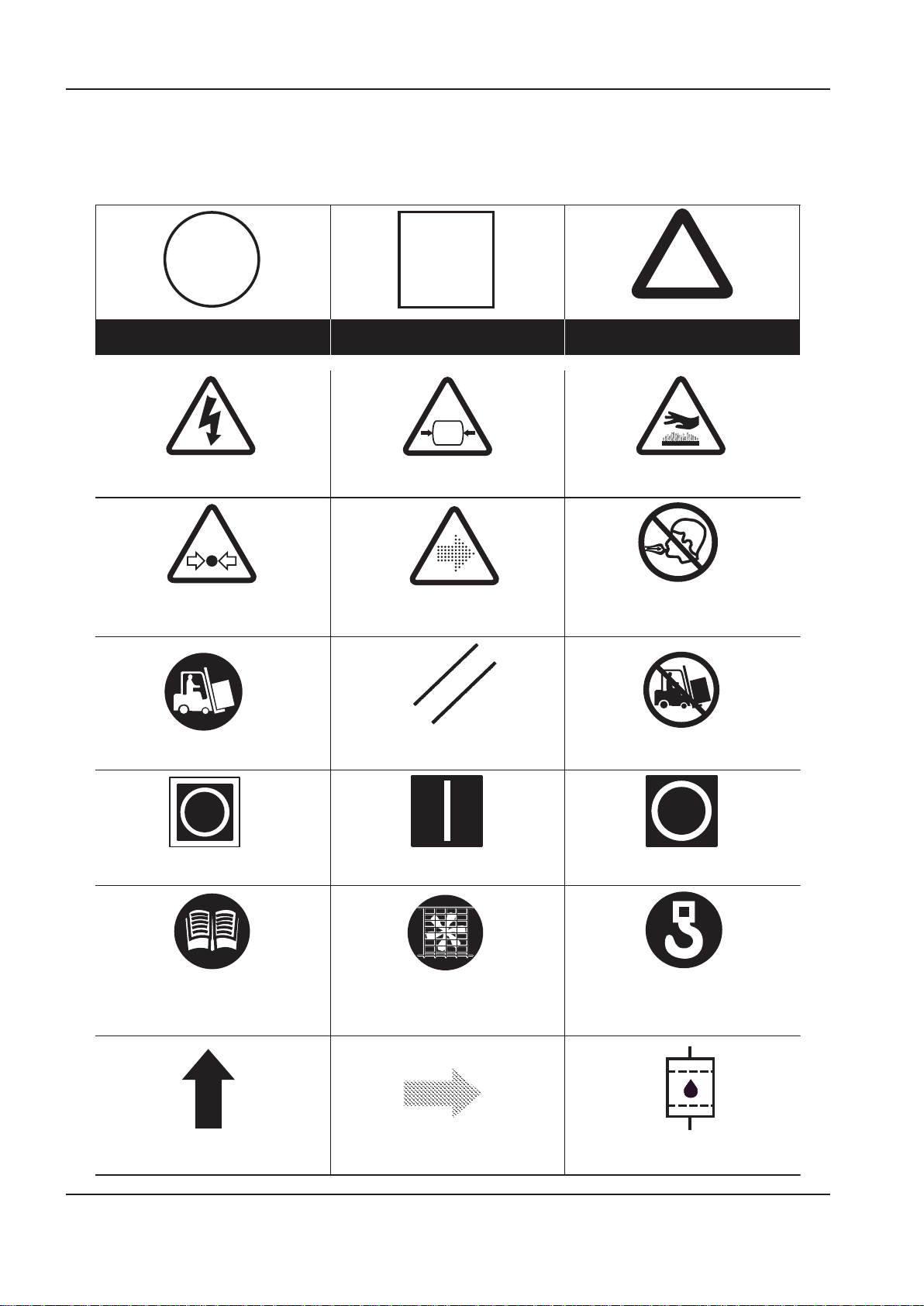
Prohibition / Mandatory Information / Instructions Warning
WARNING: Electrical shock risk WARNING − Pressurised vessel. WARNING − Hot surface.
WARNING − Pressurised component or system. WARNING − Air/gas ow or Air discharge. Do not breathe the compressed air from this
machine.
Use fork lift truck from this side only. RESET Do not use fork lift truck from this side.
O (power).On (power).Emergency Stop.
Read the Operation and Maintenance manual
before operation or maintenance of this
machine is undertaken.
Do not operate the machine without the guard
being tted.
Lifting point.
ROTATION AIR DISCHARGE COOLANT FILTER
DECALS
ISO SYMBOLS
GRAPHIC FORM AND MEANING OF ISO SYMBOLS
6 http://air.ingersollrand.com
Page 7

OPERATION AND MAINTENANCE MANUAL DECALS
http://air.ingersollrand.com 7
Page 8
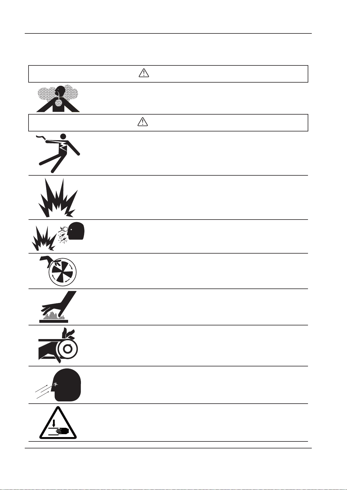
DECALS OPERATION AND MAINTENANCE MANUAL
DANGER
WARNING
ANSI SYMBOLS
GRAPHIC FORM AND MEANING OF ANSI SYMBOLS
INTAKE AIR. Can contain carbon monoxide or other contaminants. Will cause serious injury or
death. Ingersoll Rand air compressors are not designed, intended or approved for breathing air.
Compressed air should not be used for breathing air applications unless treated in accordance with
all applicable codes and regulations.
HAZARDOUS VOLTAGE. Can cause serious injury or death. Disconnect power and bleed pressure
from tank before servicing. Lockout/Tagout machine. Compressor must be connected to properly
grounded circuit. See Grounding Instructions in manual. Do not operate compressor in wet
conditions. Store indoors.
RISK OF FIRE OR EXPLOSION. Electrical arcing from compressor components can ignite ammable
liquids and vapors which can result in serious injury. Never operate the compressor near ammable
liquids or vapors. If used to spray ammable materials, keep compressor at least 20ft (6m) away
from the spray area.
HIGH PRESSURE AIR. Rusted tanks can cause explosion and severe injury or death. Receiver under
pressure. Operator should relieve tank pressure before performing maintenance. In addition to
automatic drain, operate manual drain valve weekly. Manual drain valve located at bottom of the
tank.
MOVING PARTS. Can cause serious injury. Do not operate with guards removed. Machine may start
automatically. Disconnect power before servicing. Lockout/Tagout machine.
HOT SURFACES. Can cause serious injury. Do not touch. Allow to cool before servicing.
Do not touch hot compressor or tubing.
EXPOSED MOVING BELTS AND SHEAVES.
Can cause severe injury or death.
Do not operate without guard in place. Disconnect power before servicing.
Lockout/Tagout machine.
Air ow exhaust may contain ying debris.
Safety protection should be worn at all times.
Pinch point hazard.
Keep hands clear.
8 http://air.ingersollrand.com
Page 9
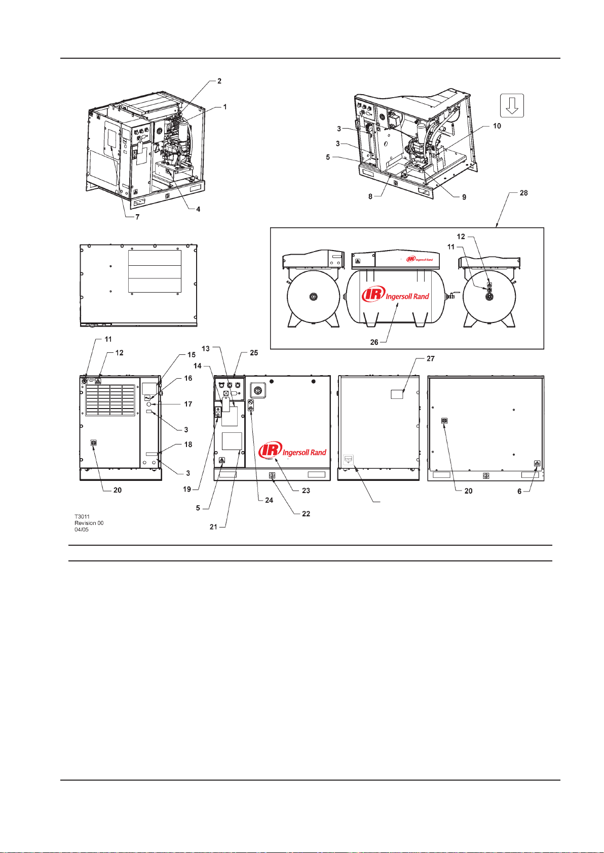
OPERATION AND MAINTENANCE MANUAL DECALS
29
Item ccn Qty. Description Item ccn Qty. Description
1 93166502 1 Decal, replacement element 12 92867498 1
2 92867530 1 Decal, warning hot surface
3 3 Decal, voltage 13 22547145 1 Decal, total air system
4 93166460 1 Decal, coolant drain Dryer packages only
5 92960593 2 Decal, warning hazardous 14 22459200 1 Tag, rotation
voltage 15 SPEC 1 Specications, compressor
6 93166478 1 Decal, condensate drain package
7 22530331 1 Decal, dryer bypass instruction 16 93166486 1 Decal, power inlet
8 23353196 1 Decal, maintenance parts 17 22141311 1 Decal, place to cover hole
9 92930585 1 Decal, pressurized vessel 18 22604276 1 Decal, multiple wiring circuit
10 93165983 1 Decal, rotation direction Dryer packages only
11 92867407 2 Decal, do not inhale 19 93493641 1 Decal, start up warning
Decal, notice air discharge
Base mount only
Contd....
http://air.ingersollrand.com 9
Page 10
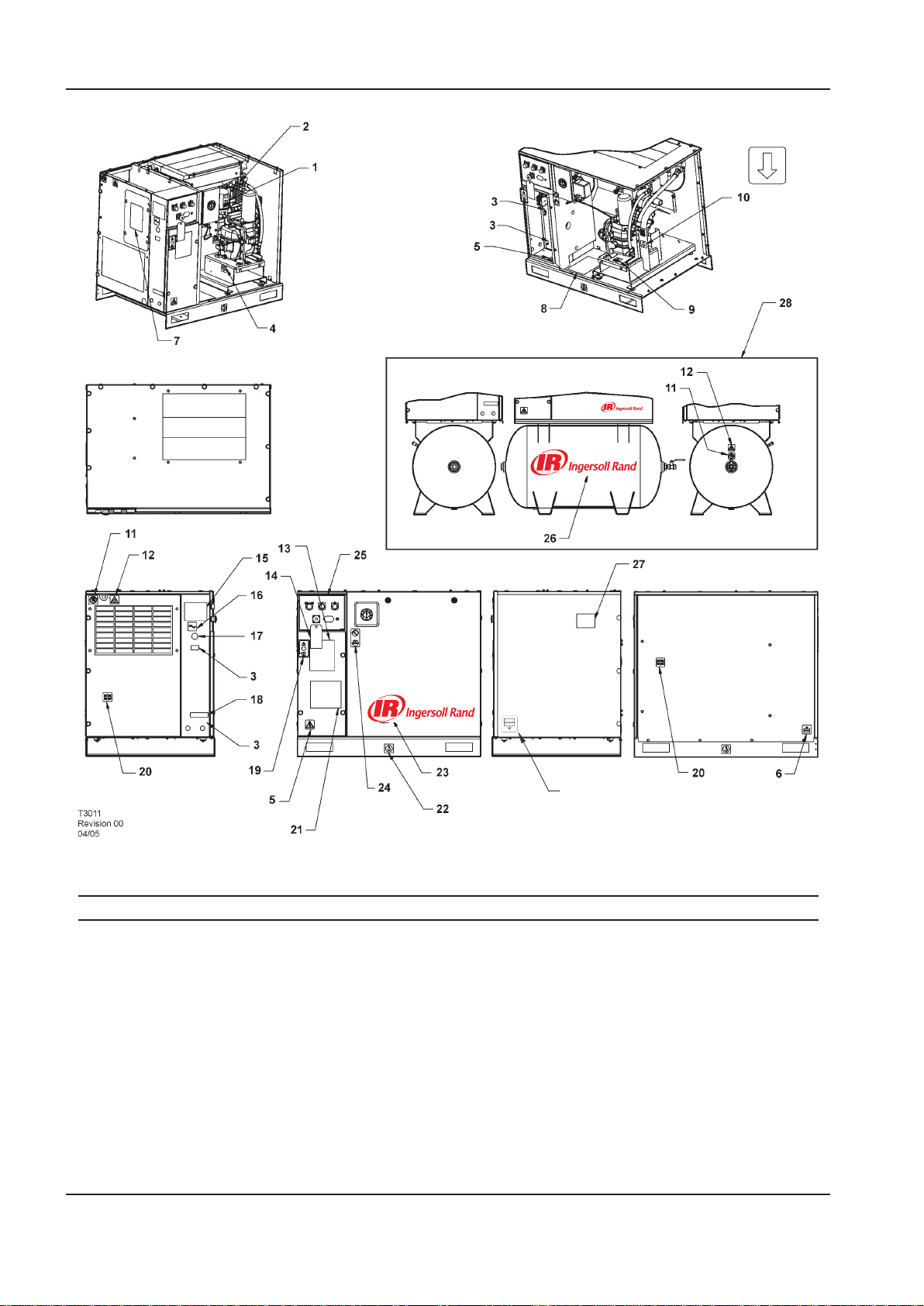
DECALS OPERATION AND MAINTENANCE MANUAL
29
Item ccn Qty. Description Item ccn Qty. Description
20 93165959 1 Decal, use guards when
running
21 1 Decal, wiring schematic
diagram
22 93171262 1 Decal, lift here both sides
Base mount only
23 22913032 1 Decal, Ingersoll Rand logo
Base mount only
22435713 1 Decal, Ingersoll Rand logo
Receiver mount only
24 92930668 1 Decal, no maintenance before
referring to manual
10 http://air.ingersollrand.com
25 22417109 1 Decal, facia
Rectangular hourmeter
22529291 1 Decal, facia
Round hourmeter
26 23038474 1 Decal, Ingersoll Rand logo
27 22454060 1 Decal, belt
28 Tank mount option
29 54618681 1 Decal, condensate drain
Page 11

OPERATION AND MAINTENANCE MANUAL SAFETY
SAFETY
DANGER
Hazard that WILL cause DEATH, SEVERE INJURY or
substantial property damage if ignored. Instructions
must be followed precisely to avoid injury or death.
WARNING
Hazard that CAN cause DEATH, SEVERE INJURY or
substantial property damage if ignored. Instructions
which must be followed precisely to avoid injury or
death.
CAUTION
Cautions call attention to instructions which must be
followed precisely to avoid damaging the product,
process or its surroundings.
NOTES
Notes are used for supplementary information.
BREATHING AIR PRECAUTION
Ingersoll Rand air compressors are not designed,
intended or approved for breathing air. Compressed
air should not be used for breathing air applications
unless treated in accordance with all applicable codes
and regulations.
GENERAL INFORMATION
Ensure that the operator reads and understands the
decals and consults the manuals before maintenance or
operation.
Ensure that the Operation and Maintenance manual is
not removed permanently from the machine.
Ensure that maintenance personnel are adequately
trained, competent and have read the Maintenance
Manuals.
Do not point air nozzles or sprayers toward anyone.
Compressed air and electricity can be dangerous.
Before undertaking any work on the compressor, ensure
that the electrical supply has been isolated and the
compressor has been relieved of all pressure.
Wear eye protection when operating or servicing
compressor.
All persons positioned near to operating machinery
should be equipped with hearing protection and given
instructions on its use in accordance with workplace
safety legislation.
Make sure that all protective covers are in place and that
the canopy/doors are closed during operation.
The specication of this machine is such that the
machine is not suitable for use in ammable gas risk
areas.
Installation of this compressor must be in accordance with
recognised electrical codes and any local Health and Safety
Codes.
The use of plastic bowls on line lters can be hazardous.
Their safety can be aected by either synthetic
lubricants, or the additives used in mineral oils.
Ingersoll Rand recommends that only lters with metal
bowls should be used on a pressurised system.
COMPRESSED AIR
Compressed air can be dangerous if incorrectly
handled. Before doing any work on the unit, ensure
that all pressure is vented from the system and that the
machine cannot be started accidentally.
WARNING
Imposing a normal or emergency stop on
the compressor will only relieve pressure
upstream of the minimum pressure valve
on top of the separator tank. If maintenance
work is required downstream of this
valve, ensure that all pressure is relieved
at the process vent point external to the
compressor.
Ensure that the machine is operating at the rated
pressure and that the rated pressure is known to all
relevant personnel.
All air pressure equipment installed in or connected to
the machine must have safe working pressure ratings of
at least the machine rated pressure.
If more than one compressor is connected to one
common downstream plant, eective isolation valves
must be tted and controlled by work procedures, so
that one machine cannot accidentally be pressurised /
over pressurised by another.
Compressed air must not be used for a direct feed to any
form of breathing apparatus or mask.
The discharged air contains a very small percentage
of compressor lubricant and care should be taken to
ensure that downstream equipment is compatible.
If the discharged air is to be ultimately released into a
conned space, adequate ventilation must be provided.
When using compressed air always use appropriate
personal protective equipment.
All pressure containing parts, especially exible hoses
and their couplings, must be regularly inspected, be free
from defects and be replaced according to the Manual
instructions.
Compressed air can be dangerous if incorrectly
handled. Before doing any work on the unit, ensure
that all pressure is vented from the system and that the
machine cannot be started accidentally.
Avoid bodily contact with compressed air.
All safety valves located in the separator tank must be
checked periodically for correct operation.
http://air.ingersollrand.com 11
Page 12

SAFETY OPERATION AND MAINTENANCE MANUAL
Do not over-pressurize the receiver tank or similar
vessels beyond design limits.
Do not use a receiver tank or similar vessels that fail
to meet the design requirements of the compressor.
Contact your distributor for assistance.
Do not drill into, weld or otherwise alter the receiver
tank or similar vessels.
Before servicing the unit, vent pressure before removing
the power to ensure that the gauge reads zero pressure.
MATERIALS
The following substances are used in the manufacture
of this machine and may be hazardous to health if used
incorrectly:
preservative grease
•
•
rust preventative
•
compressor coolant
AVOID INGESTION, SKIN CONTACT AND INHALATION
OF FUMES
TRANSPORT
WARNING
Any electrical connections or adjustments
should only be made by a suitably qualied
electrician
Close and lock all access doors when the compressor is
left unattended.
Do not use extinguishers intended for Class A or Class B
res on electrical res. Use only extinguishers suitable
for class BC or class ABC res.
Attempt repairs only in clean, dry, well lighted and
ventilated areas.
Connect the compressor only to electrical systems that
are compatible with its electrical characteristics and that
are within it’s rated capacity.
CONDENSATE DISPOSAL
As waste water regulations vary by country and region
it is the responsibility of the user to establish the
limitations and regulations in their particular area.
Ingersoll Rand and its associated distributors are happy
to advise and assist in these matters.
When loading or transporting machines ensure that the
specied lifting and tie down points are used.
Lifting equipment must be properly rated for the weight
of the compressor.
Do not work on or walk under the compressor while it is
suspended.
ELECTRICAL
Keep all parts of the body and any hand-held tools
or other conductive objects, away from exposed live
parts of the compressor electrical system. Maintain dry
footing, stand on insulating surfaces and do not contact
any other portion of the compressor when making
adjustments or repairs to exposed live parts of the
compressor electrical system.
For further information, consult Material Data Sheets for
ULTRA.
The above information contains data supplied in
support of United Kingdom Control of Substances
Hazardous to Health (C.O.S.H.H.) regulations.
12 http://air.ingersollrand.com
Page 13

OPERATION AND MAINTENANCE MANUAL GENERAL INFORMATION
22426035
REV F
GENERAL INFORMATION
PIPING AND INSTRUMENTATION
http://air.ingersollrand.com 13
Page 14

14 http://air.ingersollrand.com
GENERAL INFORMATION OPERATION AND MAINTENANCE MANUAL
KEY
1 Filter, air 21 Gauge, pressure
2 Valve, air inlet 22 Valve, relief (sirc)
3 Air end assembly 23 Filter, general purpose air
4 Motor 24 Filter, high eciency air
5 Relay, motor overload 25 Valve, check
6 Tank, separator - coarse 26 Recuperator
7 Tank, separator - ne 27 Valve, isolation (option)
8 Valve, minimum pressure 28 Moisture separator
9 Aftercooler 29 Valve, check
10 Valve, blowdown 30 Evaporator
11 Switch, pressure 31 Indicator, dew point
12 Switch, temperature 32 Valve, condensate
13 Filter, coolant 33 Tube, capillary
14 Thermostat 34 Filter drier, refrigerant
15 Cooler, oil 35 Condenser
16 Valve, pilot 36 Valve, hot gas bypass
17 Valve, relief 37 Compressor, refrigerant
18 Valve, drain 38 Valve, auto drain
19 Screen, scavenge 39 Receiver, air
20 Valve, solenoid 40 Filter
Page 15
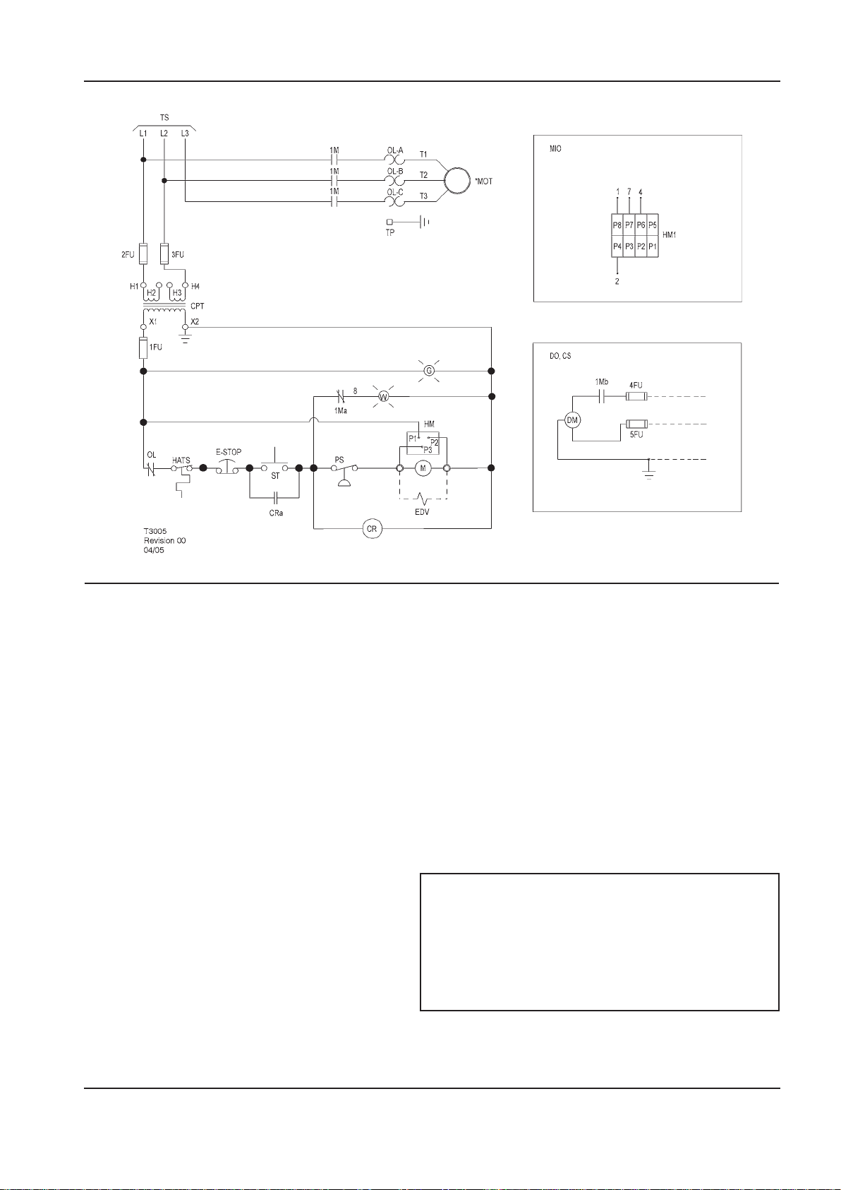
OPERATION AND MAINTENANCE MANUAL GENERAL INFORMATION
SCHEMATIC, ELECTRICAL UP6 5–15HP FV 3PH 60Hz DOL – U.S.A.
KEY
1FU,
2FU, 3FU
4FU, 5FU Fuse M Coil motor starter
1Ma Contact, auxiliary starter MIO Indicator, maintenance option
1Mb Contact, auxiliary starter MOT Motor
CPT Transformer, control
CR Relay, control PS Switch, pressure
CRa Contact, control relay ST Push button, start
CS Customer supplied 115v / 1 / 60hz TP Terminal points
DO Dryer option TS To supply
DM Motor, dryer W Standby light
EDV Valve, electric drain 120/1/50–60
E-STOP Button, emergency stop 1. (*) Furnished, mounted and wired outside of control
G Power on light 2. Circuit shown in normal position de–energized.
HM Hourmeter 3. All wiring to be marked in accordance with this
HM1
Fuse control circuit HATS Switch, high air temperature
(Instead of standard hourmeter)
OL Overload, motor starter
120/1/50–60
See transformer nameplate for wiring
connection requirements
NOTES
panel, if required by order.
schematic.
Indicator, maintenance 4. All wiring to be in accordance with NEC.
http://air.ingersollrand.com 15
Page 16
16 http://air.ingersollrand.com
GENERAL INFORMATION OPERATION AND MAINTENANCE MANUAL
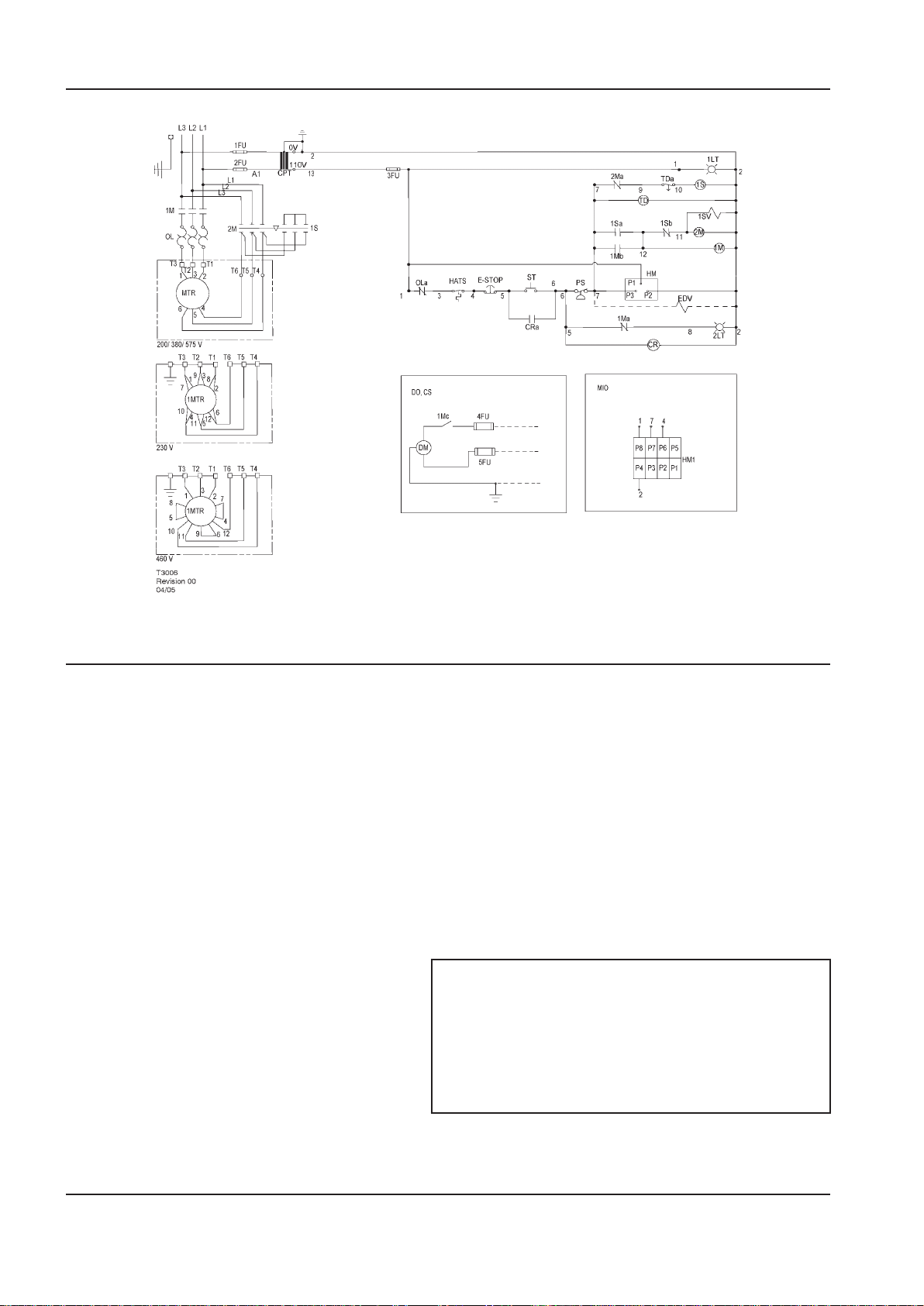
SCHEMATIC, ELECTRICAL UP6 5–15HP SD 3PH 60Hz
KEY
1FU, 2FU Fuse, primary HATS Switch, high air temperature
3FU Fuse, secondary HM Hourmeter
4FU, 5FU Fuse, dryer HM1 Indicator, maintenance
1LT Light, power on indicator (green) MIO Indicator, maintenance option
(Instead of standard hourmeter)
2LT Light, auto restart indicator (white) MTR Motor, compressor
1M Contactor, main OL Overload, main motor
1Ma, b, c Contacts, auxiliary. Main contactor OLa Contact, main motor overload
2M Contactor, delta PS Switch, pressure
2Ma, b Contacts, auxiliary. Delta contactor ST Push button, start
1S Contactor, star T D Relay, delta starting (10sec)
1Sa, b Contacts, auxiliary. Star contactor TDc Relay, delay o, contact
1SV Valve, solenoid (nc)
CPT Transformer, control
CR Relay, control 1. (*) Furnished, mounted and wired outside of control
CRa Contact, control relay 2. Circuit shown in normal position de–energized.
CS Customer supplied 115v / 1 / 60hz 3. All wiring to be marked in accordance with this
DM Motor, dryer 4. All wiring to be in accordance with NEC.
DO Dryer option
EDV Valve, electric drain (optional)
E–STOP Switch, emergency stop
NOTES
panel, if required by order.
schematic.
Page 17
OPERATION AND MAINTENANCE MANUAL GENERAL INFORMATION
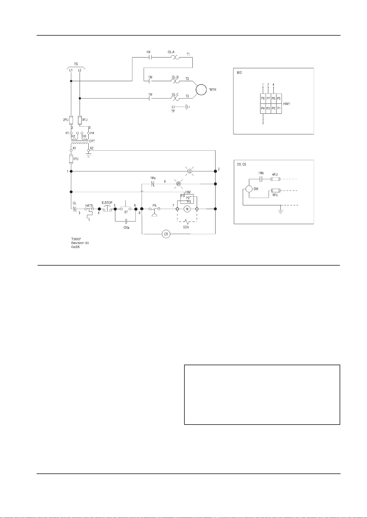
SCHEMATIC, ELECTRICAL UP6 5–15HP FV 1PH 60Hz - U.S.A.
KEY
1FU,
2FU, 3FU
4FU, 5FU Fuse, dryer MIO Indicator, maintenance option
1Ma Contact, auxiliary starter (Instead of standard hourmeter)
1Mb Contact, auxiliary starter MTR Motor,compressor
CPT Transformer, control 120/1/50–60 see OL Overload, motor starter
CR Relay, control TP Terminal points
CRa Contact, control relay TS To supply
CS Customer supplied 115v / 1 / 60hz W Standby light
DM Motor, dryer
DO Dryer option 1. (*) Furnished, mounted and wired outside of control
EDV Valve, electric drain 2. Circuit shown in normal position de–energized.
E-STOP Switch, emergency stop 3. All wiring to be marked in accordance with this
G
HM Hourmeter
HM1 Indicator, maintenance
Fuse control circuit M Coil motor starter
Transformer nameplate for wiring PS Switch, pressure
Connection requirements ST Push button, start
NOTES
panel, if required by order.
schematic.
Power on light 4. All wiring to be in accordance with NEC.
http://air.ingersollrand.com 17
Page 18
18 http://air.ingersollrand.com
GENERAL INFORMATION OPERATION AND MAINTENANCE MANUAL
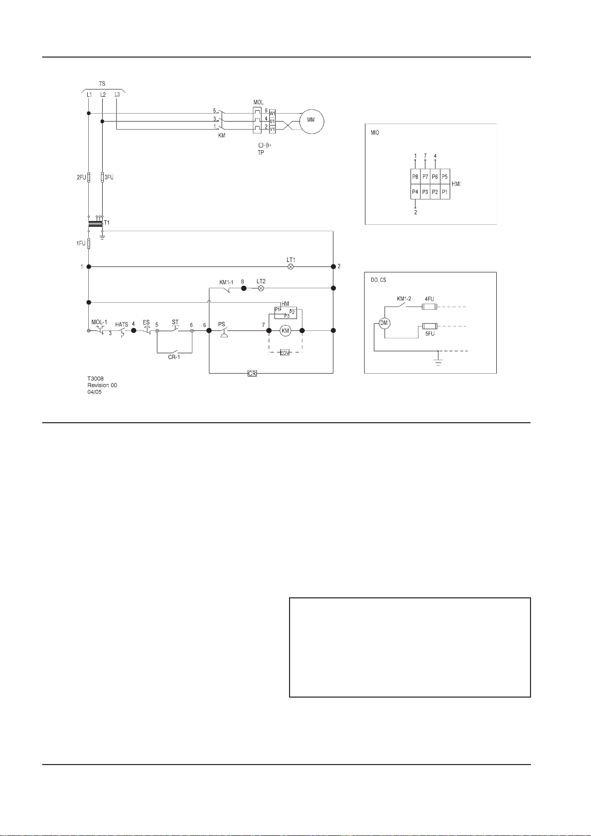
SCHEMATIC, ELECTRICAL UP5 5–15HP FV 3PH 50Hz DOL
KEY
1FU Fuse, secondary MIO Indicator, maintenance option
(Instead of standard hourmeter)
2FU, 3FU Fuse, primary MM Motor, compressor
4FU, 5FU Fuse, dryer MOL Overload, main motor
CR Relay, control MOL-1 Contact, main motor overload
CS Customer supplied 230v / 1 / 50hz PS Switch, pressure
DM Motor, dryer ST Push button, start
DO Dryer option T1 Transformer, control
EDV Valve, electric drain TP Terminal points
ES Switch, emergency stop TS To supply
HATS Switch, high air temperature
HM Hourmeter
HM1
KM Contactor, main 1. (*) Furnished, mounted and wired outside of
KM–1,2 Contacts, auxiliary. Main contactor 2. Circuit shown in normal position de–energized.
LT1 Light, power on indicator (green) 3. All wiring to be marked in accordance with this
LT2
Indicator, maintenance
NOTES
control panel, if required by order.
schematic.
Light, auto restart indicator (white) 4. All wiring to be in accordance with NEC.
Page 19
OPERATION AND MAINTENANCE MANUAL GENERAL INFORMATION
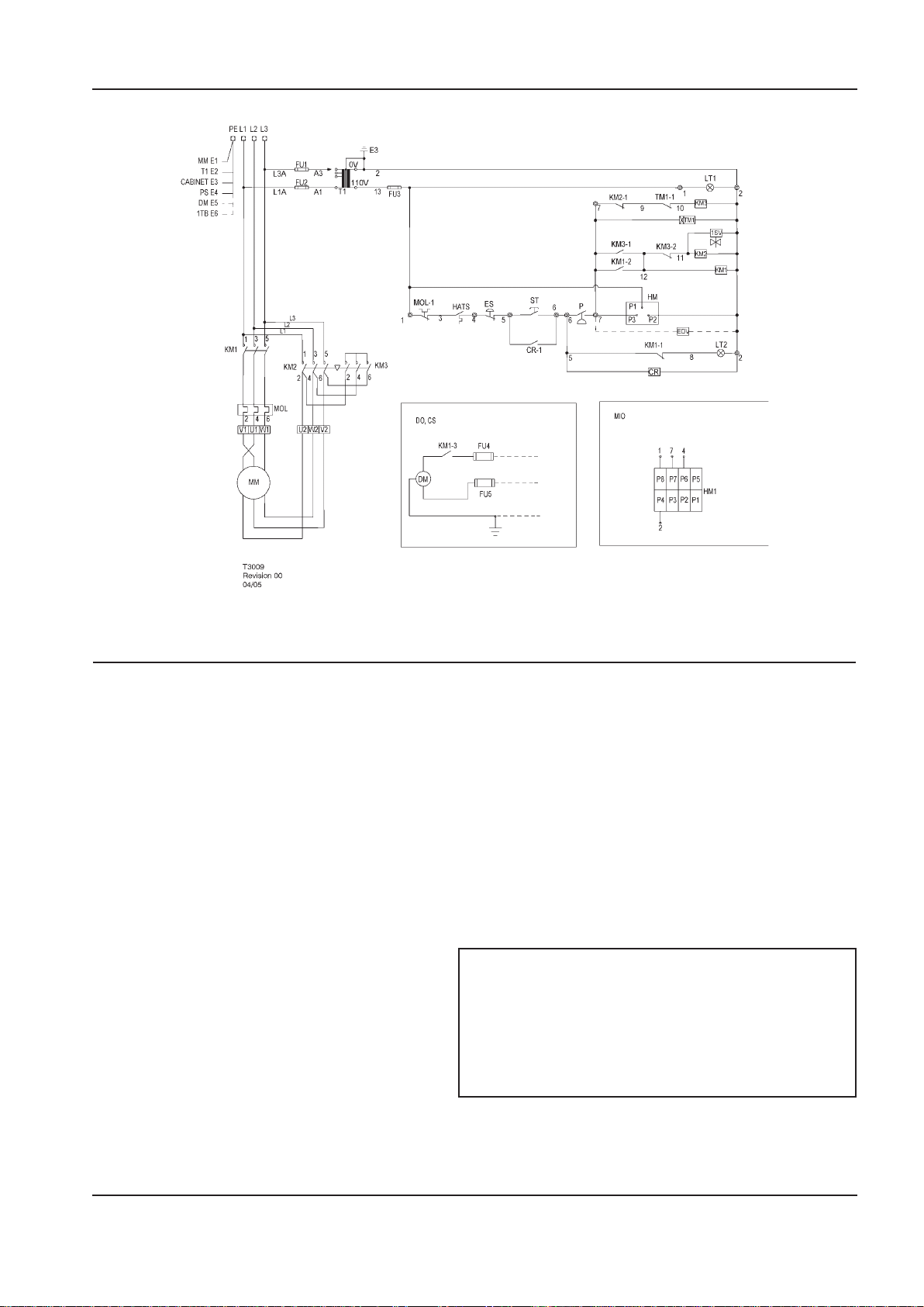
SCHEMATIC, ELECTRICAL UP5 5–15HP SD 3PH 50Hz
KEY
1SV Valve, solenoid (nc) KM2-1,2 Contacts, auxiliary. Delta contactor
CR Relay, control KM3 Contactor, star
CR-1 Contact, control relay KM3-1,2 Contacts, auxiliary. Star contactor
CS Customer supplied 230v / 1 / 50hz LT1 Light, power on indicator (green)
DM Motor, dryer LT2 Light, auto restart indicator (white)
DO Dryer option MIO Indicator, maintenance option
EDV Valve, electric drain (Instead of standard hourmeter)
HATS Switch, high air temperature MOL Overload, main motor
HM Hourmeter MOL-1 Contact, main motor overload
HM1 Indicator, maintenance ST Push button, start
MM Motor, compressor T1 Transformer, control
P Switch, pressure TM1 Relay, delta starting (10sec)
ES Switch, emergency stop TM1-1 Relay, delay o, contact
FU1, FU2 Fuse, primary
FU3 Fuse, secondary
FU4, FU5 Fuse, dryer 1. (*) Furnished, mounted and wired outside of
KM1 Contactor, main 2. Circuit shown in normal position de–energized.
KM-1,2,3 Contacts, auxiliary. Main contactor 3. All wiring to be marked in accordance with this
KM2
Contactor, delta 4. All wiring to be in accordance with NEC.
NOTES
control panel, if required by order.
schematic.
http://air.ingersollrand.com 19
Page 20
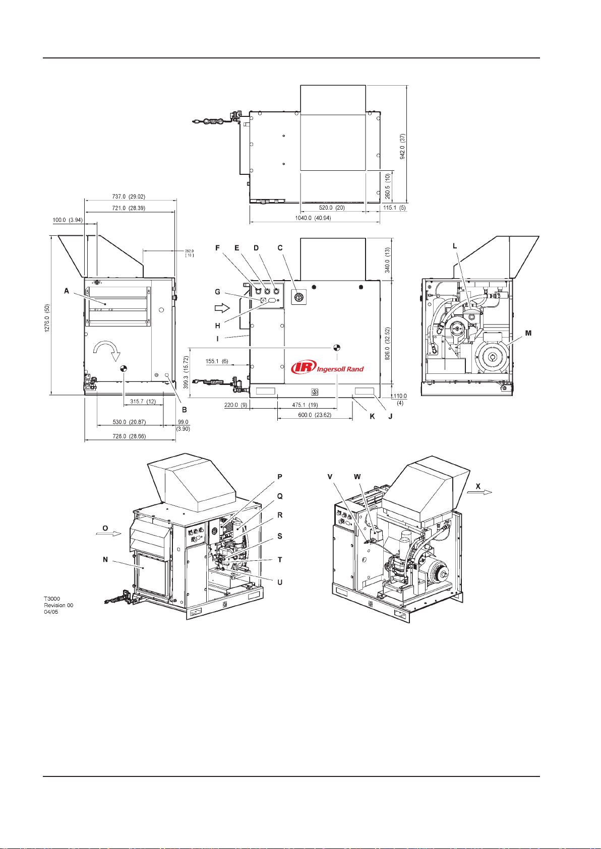
INSTALLATION / HANDLING OPERATION AND MAINTENANCE MANUAL
WITH
OPTIONAL
OUTDOOR MOD.
WITH
OPTIONAL
OUTDOOR MOD.
ROTATION
VIEW TOP
VIEW LEFT
VIEW RIGHT
VIEW FRONT
INSTALLATION/HANDLING
20 http://air.ingersollrand.com
Page 21

OPERATION AND MAINTENANCE MANUAL INSTALLATION / HANDLING
KEY
A Package pre-ller M Motor
B Hole, incoming power supply conduit N Integrated dryer (Optional)
C Gauge, pressure O Compressor and cooling air intake
D Yellow stand–by light P Filter, coolant
E Green power–on light Q Cartridge, coolant separator
F Green start push button R Valve, airend relief
G Emergency stop button S Plug, coolant ller
H Hourmeter T Sight–glass
I Starter box U Plug, coolant drain
J Lifting points V Valve, pilot
K Mounting holes (4 x 14.0mm [0.550”] diameter) W Switch, pressure
L Filter, air inlet X Cooling air exhaust
NOTES
1. Foundation or oor must be level and support all
mounting bolt locations equally. If necessary, shim
or grout the fourth bolt location.
2. Foundation bolts should protect thru nuts a
minimum of 13mm (0.50”) to allow for levelling.
3. Allow a minimum clearance of 1100mm (42”) on
the front and 920mm (36”) on the top, left right
and rear of the package for proper air circulation
and serviceability.
4. Approximate package weight: 298kg (655lbs).
5. External piping shall not exert any unresolved
moments or forces on the unit. Use pipe size as
large or larger at discharge connection.
6. There should be no plastic or pvc piping attached
to this unit or used for any lines downstream.
7. Do not pipe into a common header with a
reciprocating compressor, unless the reciprocating
compressor utilizes a discharge pulsation damper.
8. Sizing of electrical components not supplied
by Ingersoll Rand is the responsibility of the
customer and should be done in accordance with
the information on the compressor data plate and
national and local electrical codes.
All dimensions are in millimetres (inches) unless
otherwise stated.
Ensure that the correct fork lift truck slots or marked
lifting points are used whenever the machine is lifted or
transported.
UNPACKING
The compressor will normally be delivered with a
polythene cover. If a knife has to be used to remove
this cover ensure that the exterior paintwork of the
compressor is not damaged.
Ensure that all transport and packing materials are
discarded in a manner prescribed by local codes.
NOTE
http://air.ingersollrand.com 21
Page 22

INSTALLATION / HANDLING OPERATION AND MAINTENANCE MANUAL
UP-SERIES
TANK MOUNTED (80 GAL)
22 http://air.ingersollrand.com
Page 23

OPERATION AND MAINTENANCE MANUAL INSTALLATION / HANDLING
KEY
A Package pre-ller P Filter, coolant
B Hole, incoming power supply conduit Q Cartridge, coolant separator
C Gauge, pressure R Valve, airend relief
D Yellow stand–by light S Plug, coolant ller
E Green power–on light T Sight–glass
F Green start push button U Plug, coolant drain
G Emergency stop button V Valve, pilot
H Hourmeter W Switch, pressure
I Starter box X Cooling air exhaust
J Lifting points 1A Valve, ball 0.75” N.P.T.
K Mounting holes (4 x 17.5mm [0.68”] x 44.5mm
[1.75”] slots)
L Filter, air inlet 1C Location for manual receiver drain
M Motor 1D Valve, receiver relief
N Integrated dryer (Optional) 1E 0.25” discharge port for optional electric drain valve
O Compressor and cooling air intake
1B Air receiver (Ø 620.0mm x 1168.4mm LG) ( Ø 24.40”
x 46.00” LG)
NOTES
1. Foundation or oor must be level and support all
mounting bolt locations equally. If necessary, shim
or grout the fourth bolt location.
2. Foundation bolts should protect thru nuts a
minimum of 13mm (0.50”) to allow for levelling.
3. Allow a minimum clearance of 1100mm (42”) on
the front and 920mm (36”) on the top, left right
and rear of the package for proper air circulation
and serviceability.
4. Approximate package weight: 420kg (925lbs).
5. External piping shall not exert any unresolved
moments or forces on the unit. Use pipe size as
large or larger at discharge connection.
6. There should be no plastic or pvc piping attached
to this unit or used for any lines downstream.
7. Do not pipe into a common header with a
reciprocating compressor, unless the reciprocating
compressor utilizes a discharge pulsation damper.
8. Sizing of electrical components not supplied
by Ingersoll Rand is the responsibility of the
customer and should be done in accordance with
the information on the compressor data plate and
national and local electrical codes.
NOTE
All dimensions are in millimetres (inches) unless
otherwise stated.
Ensure that the correct fork lift truck slots or marked
lifting points are used whenever the machine is lifted or
transported.
UNPACKING
The compressor will normally be delivered with a
polythene cover. If a knife has to be used to remove
this cover ensure that the exterior paintwork of the
compressor is not damaged.
Ensure that all transport and packing materials are
discarded in a manner prescribed by local codes.
http://air.ingersollrand.com 23
Page 24

INSTALLATION / HANDLING OPERATION AND MAINTENANCE MANUAL
UP-SERIES
TANK MOUNTED (120 GAL)
24 http://air.ingersollrand.com
Page 25

OPERATION AND MAINTENANCE MANUAL INSTALLATION / HANDLING
KEY
A Package pre-ller P Filter, coolant
B Hole, incoming power supply conduit Q Cartridge, coolant separator
C Gauge, pressure R Valve, airend relief
D Yellow stand–by light S Plug, coolant ller
E Green power–on light T Sight–glass
F Green start push button U Plug, coolant drain
G Emergency stop button V Valve, pilot
H Hourmeter W Switch, pressure
I Starter box X Cooling air exhaust
J Lifting points 1A Valve, ball 0.75” N.P.T.
K Mounting holes (4 x 17.5mm [0.68”] x 44.5mm
[1.75”] slots)
L Filter, air inlet 1C Location for manual receiver drain
M Motor 1D Valve, receiver relief
N Integrated dryer (Optional) 1E 0.25” discharge port for optional electric drain valve
O Compressor and cooling air intake
1B Air receiver (Ø 618.0mm x 1701.0mm LG) ( Ø 24.33”
x 67.00” LG)
NOTES
1. Foundation or oor must be level and support all
mounting bolt locations equally. If necessary, shim
or grout the fourth bolt location.
2. Foundation bolts should protect thru nuts a
minimum of 13mm (0.50”) to allow for levelling.
3. Allow a minimum clearance of 1100mm (42”) on
the front and 920mm (36”) on the top, left right
and rear of the package for proper air circulation
and serviceability.
4. Approximate package weight: 430kg (946lbs).
5. External piping shall not exert any unresolved
moments or forces on the unit. Use pipe size as
large or larger at discharge connection.
6. There should be no plastic or pvc piping attached
to this unit or used for any lines downstream.
7. Do not pipe into a common header with a
reciprocating compressor, unless the reciprocating
compressor utilizes a discharge pulsation damper.
8. Sizing of electrical components not supplied
by Ingersoll Rand is the responsibility of the
customer and should be done in accordance with
the information on the compressor data plate and
national and local electrical codes.
NOTE
All dimensions are in millimetres (inches) unless
otherwise stated.
Ensure that the correct fork lift truck slots or marked
lifting points are used whenever the machine is lifted or
transported.
UNPACKING
The compressor will normally be delivered with a
polythene cover. If a knife has to be used to remove
this cover ensure that the exterior paintwork of the
compressor is not damaged.
Ensure that all transport and packing materials are
discarded in a manner prescribed by local codes.
http://air.ingersollrand.com 25
Page 26

INSTALLATION / HANDLING OPERATION AND MAINTENANCE MANUAL
UP-SERIES
TANK MOUNTED (272 LITRES)
26 http://air.ingersollrand.com
Page 27

OPERATION AND MAINTENANCE MANUAL INSTALLATION / HANDLING
KEY
A Package pre-ller P Filter, coolant
B Hole, incoming power supply conduit Q Cartridge, coolant separator
C Gauge, pressure R Valve, airend relief
D Yellow stand–by light S Plug, coolant ller
E Green power–on light T Sight–glass
F Green start push button U Plug, coolant drain
G Emergency stop button V Valve, pilot
H Hourmeter W Switch, pressure
I Starter box X Cooling air exhaust
J Lifting points 1A Valve, ball 0.75” N.P.T.
K Mounting holes (4 x 17.5mm [0.68”] x 44.5mm
[1.75”] slots)
L Filter, air inlet 1C Location for manual receiver drain
M Motor 1D Valve, receiver relief
N Integrated dryer (Optional) 1E 0.25” discharge port for optional electric drain valve
O Compressor and cooling air intake
1B Air receiver ( Ø 600.0mm x 1111.0mm LG) ( Ø 23.62”
x 43.74” LG)
NOTES
1. Foundation or oor must be level and support all
mounting bolt locations equally. If necessary, shim
or grout the fourth bolt location.
2. Foundation bolts should protect thru nuts a
minimum of 13mm (0.50”) to allow for levelling.
3. Allow a minimum clearance of 1100mm (42”) on
the front and 920mm (36”) on the top, left right
and rear of the package for proper air circulation
and serviceability.
4. Approximate package weight: 400kg (880lbs).
5. External piping shall not exert any unresolved
moments or forces on the unit. Use pipe size as
large or larger at discharge connection.
6. There should be no plastic or pvc piping attached
to this unit or used for any lines downstream.
7. Do not pipe into a common header with a
reciprocating compressor, unless the reciprocating
compressor utilizes a discharge pulsation damper.
8. Sizing of electrical components not supplied
by Ingersoll Rand is the responsibility of the
customer and should be done in accordance with
the information on the compressor data plate and
national and local electrical codes.
NOTE
All dimensions are in millimetres (inches) unless
otherwise stated.
Ensure that the correct fork lift truck slots or marked
lifting points are used whenever the machine is lifted or
transported.
UNPACKING
The compressor will normally be delivered with a
polythene cover. If a knife has to be used to remove
this cover ensure that the exterior paintwork of the
compressor is not damaged.
Ensure that all transport and packing materials are
discarded in a manner prescribed by local codes.
http://air.ingersollrand.com 27
Page 28

INSTALLATION / HANDLING OPERATION AND MAINTENANCE MANUAL
UP-SERIES
TANK MOUNTED (500 LITRES)
28 http://air.ingersollrand.com
Page 29

OPERATION AND MAINTENANCE MANUAL INSTALLATION / HANDLING
KEY
A Package pre-ller P Filter, coolant
B Hole, incoming power supply conduit Q Cartridge, coolant separator
C Gauge, pressure R Valve, airend relief
D Yellow stand–by light S Plug, coolant ller
E Green power–on light T Sight–glass
F Green start push button U Plug, coolant drain
G Emergency stop button V Valve, pilot
H Hourmeter W Switch, pressure
I Starter box X Cooling air exhaust
J Lifting points 1A Valve, ball 0.75” N.P.T.
K Mounting holes (4 x 17.5mm [0.68”] x 44.5mm
[1.75”] slots)
L Filter, air inlet 1C Location for manual receiver drain
M Motor 1D Valve, receiver relief
N Integrated dryer (Optional) 1E 0.25” discharge port for optional electric drain
O Compressor and cooling air intake
1B Air receiver (Ø 610.0mm x 1866.0mm LG) ( Ø 24.02”
x 73.46” LG)
valve
NOTES
1. Foundation or oor must be level and support all
mounting bolt locations equally. If necessary, shim
or grout the fourth bolt location.
2. Foundation bolts should protect thru nuts a
minimum of 13mm (0.50”) to allow for levelling.
3. Allow a minimum clearance of 1100mm (42”) on
the front and 920mm (36”) on the top, left right
and rear of the package for proper air circulation
and serviceability.
4. Approximate package weight: 455kg (1000lbs).
5. External piping shall not exert any unresolved
moments or forces on the unit. Use pipe size as
large or larger at discharge connection.
6. There should be no plastic or pvc piping attached
to this unit or used for any lines downstream.
7. Do not pipe into a common header with a
reciprocating compressor, unless the reciprocating
compressor utilizes a discharge pulsation damper.
8. Sizing of electrical components not supplied
by Ingersoll Rand is the responsibility of the
customer and should be done in accordance with
the information on the compressor data plate and
national and local electrical codes.
NOTE
All dimensions are in millimetres (inches) unless
otherwise stated.
Ensure that the correct fork lift truck slots or marked
lifting points are used whenever the machine is lifted or
transported.
UNPACKING
The compressor will normally be delivered with a
polythene cover. If a knife has to be used to remove
this cover ensure that the exterior paintwork of the
compressor is not damaged.
Ensure that all transport and packing materials are
discarded in a manner prescribed by local codes.
http://air.ingersollrand.com 29
Page 30
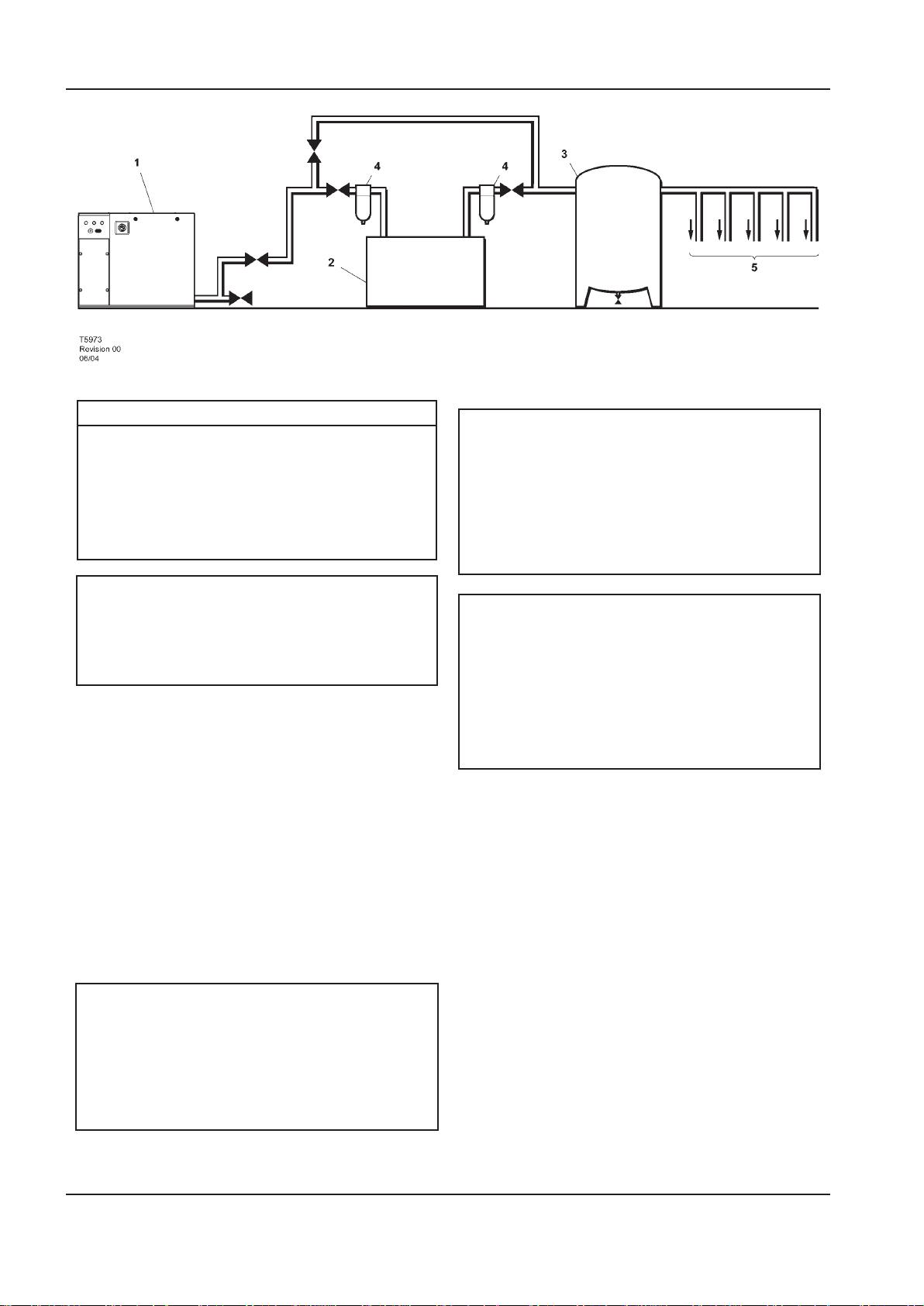
INSTALLATION / HANDLING OPERATION AND MAINTENANCE MANUAL
KEY
1.
Compressor
CAUTION
The use of plastic bowls on line lters and other
Air Receiver
2.
Air Dryer
3.
plastic air line components can be hazardous.
Their safety can be aected by either synthetic
coolants or the additives used in mineral oils.
Compressed air lters
4.
System demand points
5.
Ingersoll Rand recommends that only lters
with metal bowls should be used on any
pressurised system.
NOTE
Items [2] to [5] are optional or may be existing
items of plant. Refer to your Ingersoll Rand
distributor / representative for specic
recommendations.
LOCATION IN THE PLANT
The compressor can be installed on any level oor
capable of supporting it. A dry, well ventilated area
where the atmosphere is clean is recommended. A
minimum of 1m (3ft) should be left all around machine
for adequate service access and ventilation.
Adequate clearance needs to be allowed around and
above the machine to permit safe access for specied
maintenance tasks.
The standard compressor unit is not suitable
for operation in temperatures liable to cause
freezing as Condensate water is liable to be
produced in the after cooler and receiver where
tted.
Refer to your Ingersoll Rand distributor for
further information.
DISCHARGE PIPING
Discharge piping should be at least as large as the
discharge connection of the compressor. All piping
and ttings should be suitably rated for the discharge
pressure.
CAUTION
Ensure that the machine is positioned securely and on
a stable foundation. Any risk of movement should be
removed by suitable means, especially to avoid strain on
any rigid discharge piping.
It is essential when installing a new compressor [1],
to review the total air system. This is to ensure a safe
and eective total system. One item which should be
considered is liquid carryover. Installation of air
dryers [3] is always good practice since properly selected
CAUTION
Screw type compressors [1] should not be
installed in air systems with reciprocating
compressors without means of isolation such
and installed they can reduce any liquid carryover to
zero.
It is good practice to locate an isolation valve close to
the compressor and to install line lters [4].
as a common receiver tank. It is recommended
that both types of compressor be piped to a
common receiver using individual air lines.
It is a requirement for air dryers covered under AirCare
that correctly sized Ingersoll Rand pre and afterlters
are installed.
30 http://air.ingersollrand.com
Page 31
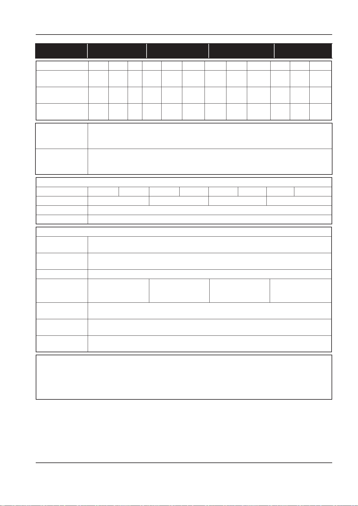
OPERATION AND MAINTENANCE MANUAL INSTALLATION / HANDLING
60Hz UP6 5 UP6 7 UP6 10 UP6 15c
COMPRESSOR 125 150 210 125 150 210 125 150 210 125 150 210
Operating pressure PSIG (bar)
Factory set reload
pressure PSIG (bar)
Flow rate CFM
(m3/MIN)
Airend discharge
temperature trip
point.
Ambient operating
temperature
(min.) →(max.)
MOTOR
Motor enclosure ODP TEFC ODP TEFC ODP TEFC ODP TEFC
Nominal power 5HP 7.5HP 10HP 15HP
Speed 3500 RPM
Insulation class F
GENERAL DATA
Residual coolant
content
Separator vessel
capacity
Coolant capacity 1.2 gallons (4.5 Litres)
Sound pressure
level to
CAGI-PNEUROP
Weight-base
mount unit
Weight-80 gallon
Receiver mounted
Weight-120 gallon
Receiver mounted
CAUTION
230/460 Dual voltage machines are tted with a decal to advise the correct voltage as connected from the factory.
There is a decal tted to the starter door describing the procedure to change the connections for the alternative
voltage.
Rewiring should only be eected by a competent Electrician.
125
(8.6)
110
(7.58)
18.5
(0.52)
150
(10.3)
130
(8.96)
16.0
(0.45)
-- 125
(8.6)
-- 110
(7.58)
-- 28.0
(0.79)
150
(10.3)
130
(8.96)
25.0
(0.71)
210
(14.5)
180
(12.41)
17.5
(0.50)
125
(8.6)
110
(7.58)
38.0
(1.08)
150
(10.3)
130
(8.96)
34
(0.96)
210
(14.5)
180
(12.41)
24.0
(0.68)
(7.58)
(1.55)
228°F (109°C)
36°F (+2°C) → 105°F (+40°C)
3ppm (3 mg/m3)
0.8 gallons (3 Litres)
65 dB(A) 65 dB(A) 68 dB(A) 69 dB(A)
295kg (650lb)
420kg (925lb)
436kg (960lb)
125
(8.6)
110
55.0
150
(10.3)
130
(8.96)
50.0
(1.42)
210
(14.5)
180
(12.41)
38.0
(1.08)
http://air.ingersollrand.com 31
Page 32
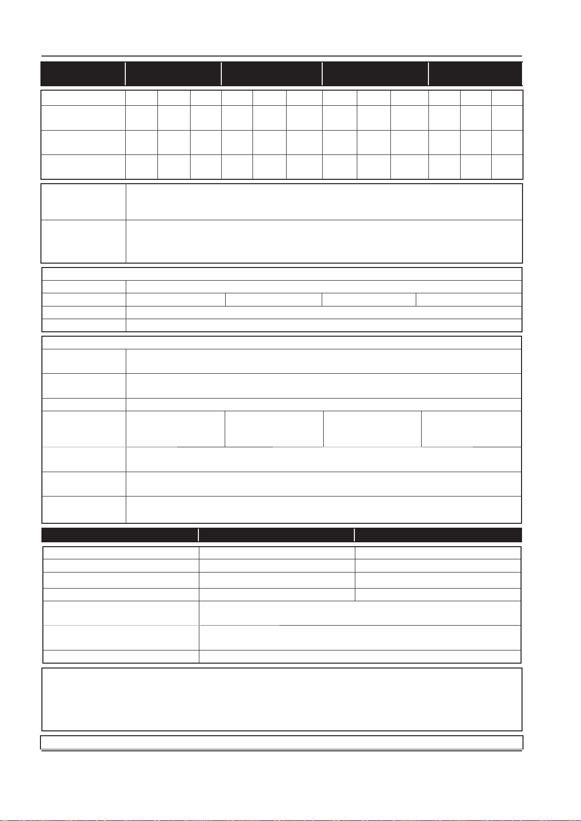
INSTALLATION / HANDLING OPERATION AND MAINTENANCE MANUAL
50Hz UP5 4 UP5 5 UP5 7 UP5 11c
COMPRESSOR 8 10 14.5 8 10 14.5 8 10 14.5 8 10 14.5
Operating pressure
PSIG (bar)
Factory set reload
pressure PSIG (bar)
Flow rate CFM
(m3/MIN)
Airend discharge
temperature trip
point.
Ambient operating
temperature
(min.) →(max.)
MOTOR
Motor enclosure TEFC
Nominal power 4KW 5.5KW 7.5KW 11KW
Speed
Insulation class F
GENERAL DATA
Residual coolant
content
Separator vessel
capacity
Coolant capacity 1.2 gallons (4.5 Litres)
Sound pressure
level to
CAGI-PNEUROP
Weight-base
mount unit
Weight-272 LitresReceiver mounted
Weight-500 Litres
Receiver mounted
115
(8)
100
(7.58)
19.5
(0.55)
145
(10)
125
(8.96)
16.0
(0.45)
210
(14.5)
-- 100
-- 29.0
115
(8)
(7.93)
(0.82)
145
(10)
125
(9.66)
26.0
(0.74)
(13.10)
210
(14.5)
180
18.0
(0.51)
115
(8)
100
(7.93)
38.0
(1.08)
228°F (109°C)
36°F (+2°C) → 105°F (+40°C)
2900 RPM
3ppm (3 mg/m3)
0.8 gallons (3 Litres)
65 dB(A) 65 dB(A) 68 dB(A) 69 dB(A)
295kg (650lb)
420kg (925lb)
454kg (1000lb)
145
(10)
125
(9.66)
34
(0.96)
210
(14.5)
180
(13.10)
24.0
(0.68)
115
(8)
100
(7.93)
56.5
(1.60)
145
(10)
125
(9.66)
50.0
(1.92)
210
(14.5)
180
(13.1)
38.0
(8.6)
DRYER ENGINEERING DATA 60Hz 50Hz
Electrical supply 115V - 1ph - 60Hz 230V - 1ph - 50Hz
L.R.A. current (Amps) 30.0 12.6
F.L.A. current (Amps) 5.0 2.7
Total installed power (kW) 0.46 0.47
Electrical protection class (std) NEMA 1
(IP 20)
Factory refrigerant charge (lb/g) 0.78 lb
354 g
Regeration type 134 A
CAUTION
230/460 Dual voltage machines are tted with a decal to advise the correct voltage as connected from the factory.
There is a decal tted to the starter door describing the procedure to change the connections for the alternative
voltage.
Rewiring should only be eected by a competent Electrician.
ELECTRICAL DATA-UP6 5
32 http://air.ingersollrand.com
Page 33
OPERATION AND MAINTENANCE MANUAL INSTALLATION / HANDLING
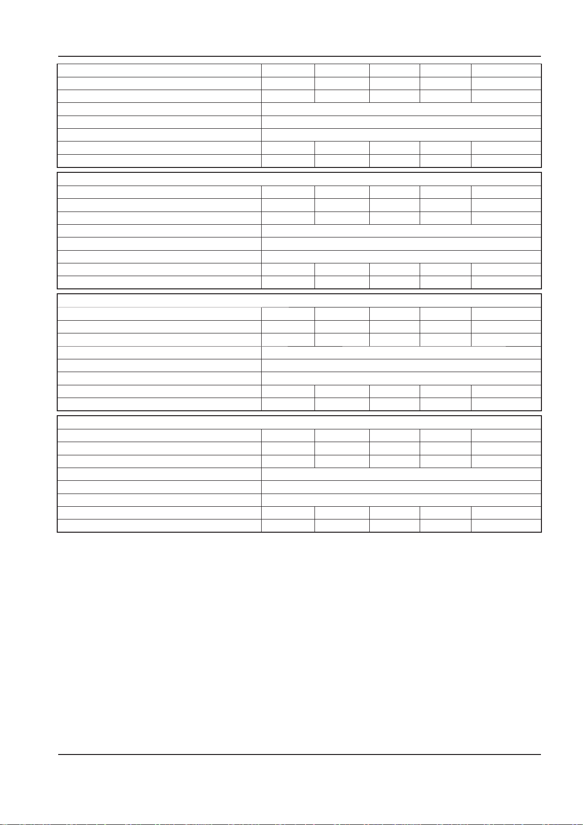
Standard voltage 230V/1PH 200V 230V/3PH 460V 575V
Full load current (maximum) 23.5A 15.5A 13.5A 6.8A 5.4A
Starting current DOL (Star Delta) - - - - Starting time DOL (Star Delta) 3–5 Sec (7–10 Sec)
Starts per hour (maximum) 6
Control voltage 120VAC
Recommended fuse rating See note 1 40A 25A 20A 10A 8A
Recommended wire size AWG See note 2 8 10 12 14 14
ELECTRICAL DATA-UP6 7.5
Standard voltage 230V/1PH 200V 230V/3PH 460V 575V
Full load current (maximum) 34.1A 22.7A 19.7A 9.9A 7.9A
Starting current DOL (Star Delta) - - - - Starting time DOL (Star Delta) 3–5 Sec (7–10 Sec)
Starts per hour (maximum) 6
Control voltage 120VAC
Recommended fuse rating See note 1 50A 35A 35A 15A 12A
Recommended wire size AWG See note 2 6 8 10 14 14
ELECTRICAL DATA-UP6 10
Standard voltage 230V/1PH 200V 230V/3PH 460V 575V
Full load current (maximum) - 29.8A 26.0A 13.0A 10.3A
Starting current DOL (Star Delta) - - - - Starting time DOL (Star Delta) 3–5 Sec (7–10 Sec)
Starts per hour (maximum) 6
Control voltage 120VAC
Recommended fuse rating See note 1 - 50A 45A 20A 15A
Recommended wire size AWG See note 2 - 8 8 12 14
ELECTRICAL DATA-UP6 15c
Standard voltage 230V/1PH 200V 230V/3PH 460V 575V
Full load current (maximum) - 43.2A 37.6A 18.8A 15.1A
Starting current DOL (Star Delta) - - - - Starting time DOL (Star Delta) 3–5 Sec (7–10 Sec)
Starts per hour (maximum) 6
Control voltage 120VAC
Recommended fuse rating See note 1 - 75A 65A 30A 25A
Recommended wire size AWG See note 2 - 4 6 10 10
1. If a circuit breaker is selected it should only be a magnetic trip type, set above the anticipated starting current
of the machine, but below the maximum prospective fault current for the circuit. The circuit breaker or fuseable
disconnect must be capable of breaking the prospective fault current at its terminals.
2. PVC/PVC Type Calculated using the following
conditions:
PVC insulated cable, armoured, copper
i)
conductors.
Cable clipped to a wall, in free air.
ii)
Ambient temperature of 40°C (104°F) and relative
iii)
20m (65ft) cable run.
iv)
Volt drop limited to –10% during starting, –4%
v)
during normal running.
Protected by the circuit breaker listed above.
vi)
humidity of 40%.
http://air.ingersollrand.com 33
Page 34
INSTALLATION / HANDLING OPERATION AND MAINTENANCE MANUAL
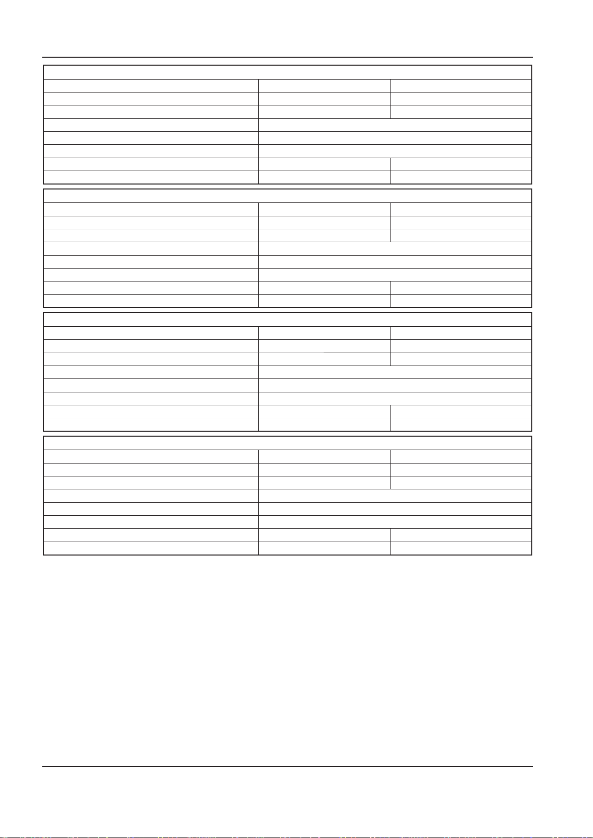
ELECTRICAL DATA-UP5 4
Standard voltage 380V 400V
Full load current (maximum) 8.9A 8.5A
Starting current DOL (Star Delta) 66 63
Starting time DOL (Star Delta) 3–5 Sec (7–10 Sec)
Starts per hour (maximum) 6
Control voltage 120VAC
Recommended fuse rating See note 1 16A 16A
Recommended wire size See note 2 4 mm2Cu 4 mm2 Cu
ELECTRICAL DATA-UP5 5.5
Standard voltage 380V 400V
Full load current (maximum) 11.8A 11.2A
Starting current DOL (Star Delta) 100 95
Starting time DOL (Star Delta) 3–5 Sec (7–10 Sec)
Starts per hour (maximum) 6
Control voltage 120VAC
Recommended fuse rating See note 1 16A 16A
Recommended wire size See note 2 4 mm2Cu 4 mm2 Cu
ELECTRICAL DATA-UP5 7.5
Standard voltage 380V 400V
Full load current (maximum) 16.9A 15.6A
Starting current DOL (Star Delta) 121 (94) 114 (52)
Starting time DOL (Star Delta) 3–5 Sec (7–10 Sec)
Starts per hour (maximum) 6
Control voltage 120VAC
Recommended fuse rating See note 1 20A 20A
Recommended wire size See note 2 4 mm2Cu 4 mm2 Cu
ELECTRICAL DATA-UP5 11c
Standard voltage 380V 400V
Full load current (maximum) 23.0A 21.9A
Starting current DOL (Star Delta) (79) (75)
Starting time DOL (Star Delta) 3–5 Sec (7–10 Sec)
Starts per hour (maximum) 6
Control voltage 120VAC
Recommended fuse rating See note 1 32A 32A
Recommended wire size See note 2 6 mm2Cu 6 mm2 Cu
1. If a circuit breaker is selected it should only be a
magnetic trip type, set above the anticipated starting
current of the machine, but below the maximum
prospective fault current for the circuit. The circuit
breaker or fuseable disconnect must be capable of
breaking the prospective fault current at its terminals.
2. PVC/PVC Type Calculated using the following
conditions:
PVC insulated cable, armoured, copper
i)
conductors.
ii)
Cable clipped to a wall, in free air.
iii)
Ambient temperature of 40°C (104°F) and relative
humidity of 40%.
iv)
20m (65ft) cable run.
v)
Volt drop limited to –10% during starting, –4%
during normal running.
vi)
Protected by the circuit breaker listed above.
34 http://air.ingersollrand.com
Page 35

OPERATION AND MAINTENANCE MANUAL INSTALLATION / HANDLING
If there are any deviations from the above, or special
regulations apply, the installation must be planned by a
competent, qualied engineer.
NOTE
All data applies to standard product only.
ELECTRICAL DATA
An independent electrical isolator or disconnect should
be installed adjacent to the compressor.
Feeder cables/wires should be sized by the customer/
electrical contractor to ensure that the circuit is
balanced and not overloaded by other electrical
equipment. The length of wiring from a suitable
electrical feed point is critical as voltage drops may
impair the performance of the compressor.
Feeder cables / wires connections to isolator or
disconnect should be tight and clean.
The applied voltage must be compatible with the motor
and compressor data plate ratings.
The control circuit transformer has dierent voltage
tappings. Ensure that these are set for the specic
applied voltage prior to starting.
CAUTION
Never test the insulation resistance of any part
of the machines electrical circuits, including the
motor without completely disconnecting the
electronic controller (where tted).
CAUTION
Ensure that the motor rotates in the correct
direction as indicated by direction arrows.
http://air.ingersollrand.com 35
Page 36

OPERATING INSTRUCTIONS OPERATION AND MAINTENANCE MANUAL
OPERATING INSTRUCTIONS
GENERAL OPERATION
The compressor is an electric motor driven, single
stage screw compressor, complete with accessories
piped, wired and base plate mounted. It is a totally self
contained air compressor package.
The standard compressor is designed to operate in
an ambient range of 35.6°F - 104°F (2°C to 40°C). The
maximum temperature is applicable up to a maximum
elevation of 3280ft (1000m) above sea level. Above this
altitude signicant reduction in maximum allowable
ambient temperature is required.
Compression in the screw type air compressor is created
by the meshing of two (male & female) helical rotors.
The air/coolant mixture discharges from the compressor
into the separation system. This system removes all
but a few PPM of the coolant from the discharge air.
The coolant is returned to the cooling system and
the air passes through the aftercooler and out of the
compressor.
Cooling air is moved through the coolers by the cooling
fan and discharged from the machine.
CAUTION
Cooling air is drawn in at the rear of the machine
package passing through the lter and cooler
before being discharged from the top of
the machine. Care should be taken to avoid
blocking the airow, or causing any restriction
in excess of the maximum backpressure allowed
for ducting.
WARNING
When the unit stops running as the result of low
air demand, it may restart and return to load at
any time.
Safety of operation is provided as the compressor
will shut down if excessive temperatures or electrical
overload conditions should occur.
CAUTION
This unit is not designed or intended to operate
when contaminated with silicone. Lubricants,
greases or other items containing silicone
should not be used on this unit.
CAUTION
LOW DEMAND APPLICATIONS
During periods of low demand, the compressor
may not reach its normal operating
temperature. Sustained operation at low
demand can result in the build up of condensate
in the coolant. If this situation occurs, the
lubricating characteristics of the coolant can
be impaired which may lead to damage of the
compressor.
THE COMPRESSOR SHOULD BE ALLOWED
AMPLE LOADED RUNNING TIME OF AT LEAST 10
MINUTES PER HOUR DURING NORMAL DAILY
USE.
Do not direct the airow at face or eyes.
By cooling the discharge air, much of the water vapour
naturally contained in the air is condensed and may be
drained from the downstream piping and equipment.
The coolant system consists of a sump, cooler,
thermostatic valve and a lter. When the unit is
operating, the coolant is pressurized and forced to the
compressor bearings.
The compressor load control system is automatic on-
o line. This allows the compressor to maintain a set
discharge line pressure by varying output capacity to
match the system demand. The unit is provided with
an automatic stop and restart system for use in plants
where the air demand varies suciently to allow a
compressor to shut down and save power. Signicant
system volume will assist this and is recommended.
When the compressor is equipped with the optional
dryer, the dryer will cycle on and o with the
compressor.
36 http://air.ingersollrand.com
Page 37
OPERATION AND MAINTENANCE MANUAL OPERATING INSTRUCTIONS
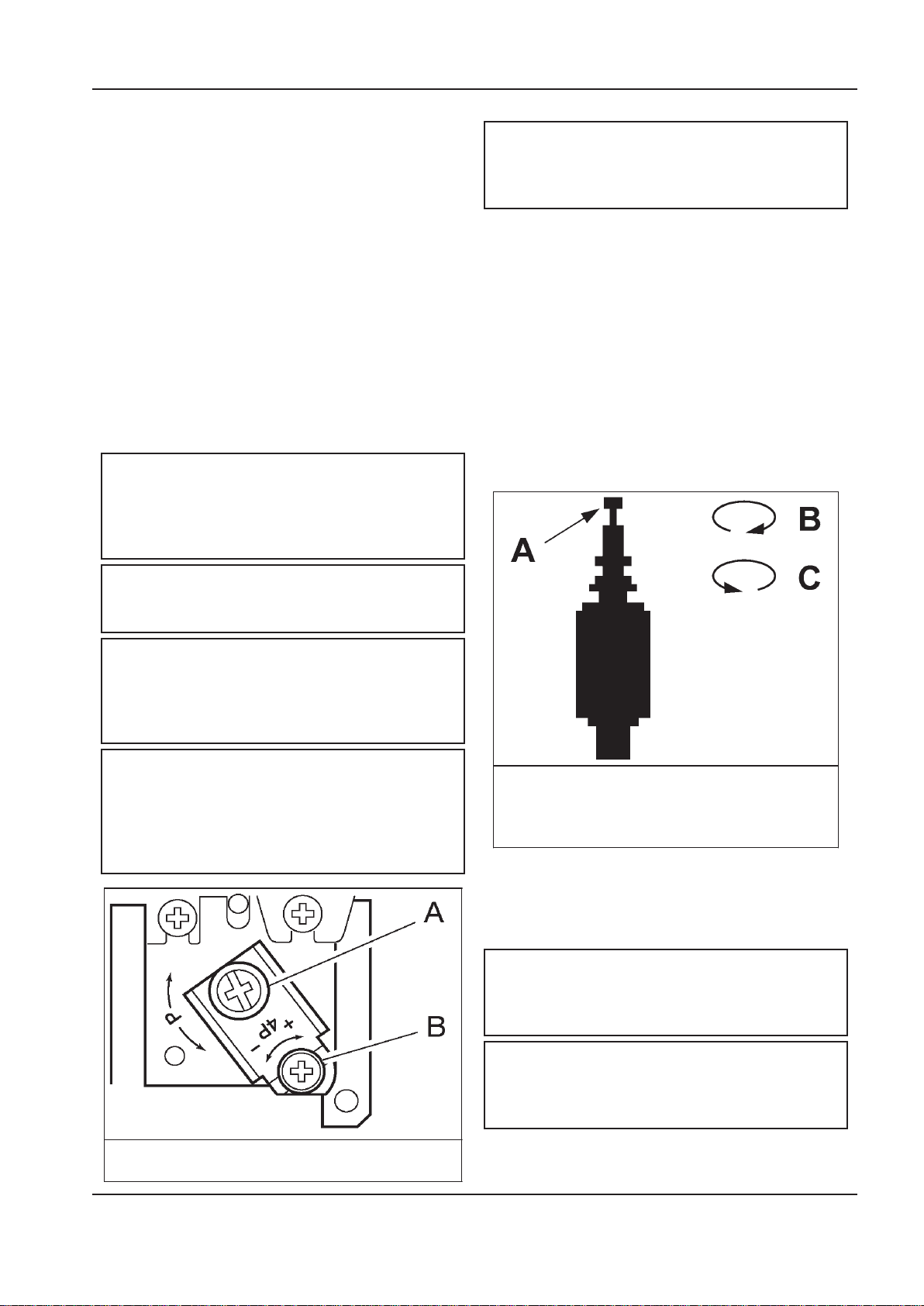
A. Upper Pressure Setting
B. Pressure Differential
Auxiliary Valve.
A. Knob
B. Clockwise
C. Counterclockwise
COMPRESSOR CONTROLS
Direct online starting:
The compressor is equipped for Automatic Start & Stop
Control. When the receiver tank pressure reaches the
factory pre–set maximum pressure, the pressure switch
stops the unit. When the receiver tank pressure drops
below the factory pre–set minimum. The pressure
switch resets and restarts the unit.
The pressure switch cover can be removed by
unscrewing the two screws holding the cover.
Pressure switch adjustment:
The compressor package will cut–in and cut–out at
factory preset pressure settings. Adjust the pressure
switch only if absolutely necessary.
Adjustments are to be carried out only when the switch
is mounted, under pressure and voltage–free.
WARNING
High voltage is present at the pressure switch
contacts when the power supply is connected.
Disconnect, lock and tag main power supply
before making adjustments.
WARNING
AUTOMATIC START & STOP CONTROL
NOTE
Automatic Start & Stop Control is intended for
use when the motor will start no more than 6
times per hour.
When the receiver tank pressure reaches the factory
pre–set maximum pressure, the pressure switch stops
the unit. When the receiver tank pressure drops below
the factory pre–set minimum, the pressure switch resets
and restarts the unit.
DUAL CONTROL
Select either automatic start and stop control or
constant speed control by adjusting the knob on the
auxiliary valve. For automatic start and stop control, turn
the knob on the auxiliary valve fully clockwise to disable
the auxiliary valve. The pressure switch will then start
and stop the unit.
Do not adjust the pressure switch to exceed the
maximum discharge pressure of the unit.
NOTE
When replacing the pressure switch cover,
ensure the selector knob on the cover and
the lever on the switch are both in the ”OFF”
position.
NOTE
When the compressor is equipped with the
optional dryer and lters, the pressure switch
dierential should be increased 10psi to account
for the added pressure drop of the lters and
dryer.
Select constant speed control if the unit restarts in less
than 10 minute intervals or runs more than 40 minutes
per hour. Turn the knob fully counterclockwise to run
the unit continually.
NOTE
The auxilIary valve is factory pre–set at 5 psig
(0,3 bar) lower than the factory pressure switch
setting.
CAUTION
http://air.ingersollrand.com 37
Running unloaded with no air demand, will
cause the unit to be shuto by the pressure
switch.
Page 38
OPERATING INSTRUCTIONS OPERATION AND MAINTENANCE MANUAL
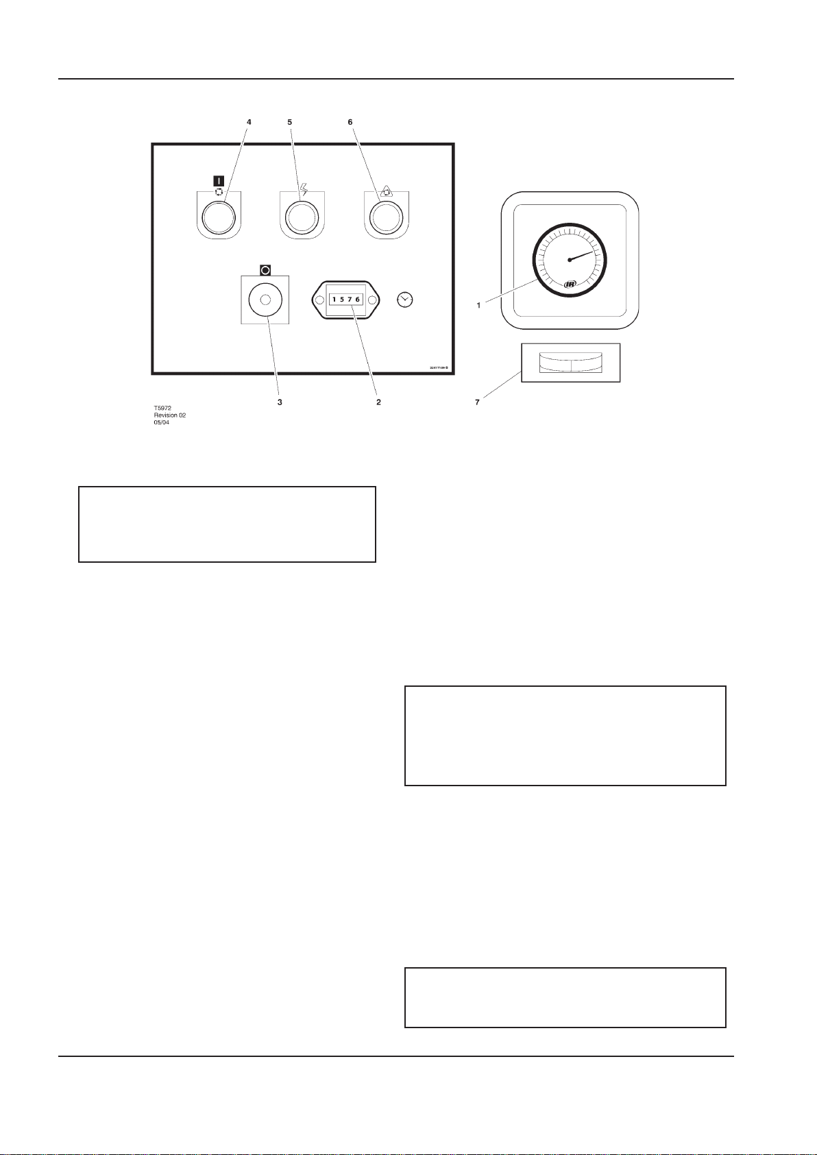
1. PRESSURE GAUGE
Indicates the system pressure.
WARNING
DO NOT operate the compressor at discharge
pressures exceeding the maximum operating
pressure.
2. HOURMETER
Records the total running time of the compressor.
3. STOP BUTTON / EMERGENCY STOP
When depressed will stop the compressor
immediately. The ’Power on’ indicator will remain
illuminated. The STOP button must be released
before the compressor can be restarted.
4. ON PUSH BUTTON SWITCH
When depressed will cause the unit to start and
run in a loaded condition if there is a demand for
air. If there is no demand, the machine will stop
automatically.
5. POWER ON INDICATOR LIGHT (Green)
Indicates the presence of control voltage.
6. STOPPED/AUTO RESTART INDICATOR LIGHT
(Amber)
Will illuminate when the machine has shut-down
due to low air demand. The machine will restart
and load automatically as soon as the demand for
air returns.
7. DEW POINT INDICATOR (Dryer Option)
Green indicates good dew point. Red indicates
ew point above 50°F (10°C) Blue indicates
freezing.
PRIOR TO STARTING
1. Make visual check of the machine, ensure that
all guards secure and that nothing is obstructing
the proper ventilation of, or free access to the
machine.
2. Check coolant level. Add if necessary.
3. Make sure air discharge valve is open.
4. Turn on electrical isolator or disconnect. The
Power on (5) indicator will light, indicating that
line and control voltages are available.
5. Check direction of rotation at initial start or
following interruption in power supply.
WARNING
Make sure that all protective covers are in place.
Cooling air ow exhaust may contain ying
debris. Safety protection should be worn at all
times to avoid injury.
STARTING
1. Press the START button. The compressor will start
and then load automatically.
NORMAL/EMERGENCY STOPPING
1. Press STOP button (3) and the compressor will
stop immediately.
2. Turn o electrical isolator or disconnect.
CAUTION
After shutdown never allow unit to stand idle with
pressure in receiver/separator system.
38 http://air.ingersollrand.com
Page 39
OPERATION AND MAINTENANCE MANUAL MAINTENANCE
MAINTENANCE
MAINTENANCE SCHEDULE
UP Series Maintenance Schedule
PERIOD MAINTENANCE
Each 24 hours operation Check the coolant level and replenish if necessary.
Visual check of machine for any leaks,
dust build up or unusual noise or
vibration
When compressor is receiver mounted Drain air receiver of condensate, or check that automatic drain is
Visual check condition of package prelter
First 150 hours Change the coolant lter.
Each month or 100 hours Remove and clean package pre-lter, replace if needed
Each year or 2000 hours Check the operation of the high temperature protection switch (109˚C).
1 year external and 6 years internal
pressure vessel inspection.
Frequency may be otherwise dened
by local or national legislation.
Every two years or 8000 hours Change drive belts.
Every 4 years or 16000 hours Replace all hoses.
Report immediately, contact Ingersoll Rand authorized distributor for
assistance if in doubt.
operating.
Blow clean if needed.
Check the cooler(s) for build up of foreign matter. Clean if necessary by
blowing out with air or by pressure washing.
Replace elements in IRGP and IRHE lters.
Change the coolant lter.
Check scavenge screen for blockage, clean if required.
Change the separator element.
Change the Air Filter element.
Take coolant sample for uid analysis.
Change the package pre–lter.
Check Drive Belts.
Motors without grease ttings - Replace sealed bearings
Separator vessel and air receiver when tted.
Fully inspect all external surfaces, and ttings. Report any excessive
corrosion, mechanical or impact damage, leakage or other
deterioration.
Replace the Ultra at whichever interval occurs rst.
Check and replace all items included within 2000 hour service.
Fit the following reconditioning parts as appropriate:
Solenoid valves
Inlet valve kit
Minimum Pressure valve kit
Thermostatic Valve Kit
Check motors with grease ttings and grease per motor data tag
Fit replacement electrical contactor tips.
Motors without grease ttings - Replace sealed bearings
http://air.ingersollrand.com 39
Page 40

40 http://air.ingersollrand.com
MAINTENANCE OPERATION AND MAINTENANCE MANUAL
ROUTINE MAINTENANCE
This section refers to the various components which
require periodic maintenance and replacement.
It should be noted that the intervals between service
requirement may be signicantly reduced as a
consequence of poor operating environment. This
would include eects of atmospheric contamination
and extremes of temperature.
The SERVICE/MAINTENANCE CHART indicates the various
components’ descriptions and the intervals when
maintenance has to take place. Oil capacities, etc., can
be found in the GENERAL INFORMATION section of this
manual.
Compressed air can be dangerous if incorrectly
handled. Before doing any work on the unit, ensure
that all pressure is vented from the system and that the
machine cannot be started accidentally.
CAUTION
Before beginning any work on the compressor,
open, lock and tag the main electrical
disconnect and close the isolation valve on
the compressor discharge. Vent pressure from
the unit by slowly unscrewing the coolant ll
cap one turn. Unscrewing the ll cap opens a
vent hole, drilled in the cap, allowing pressure
to release to atmosphere. Do not remove the
ll cap until all pressure has vented from the
unit. Also vent piping by slightly opening the
drain valve. When opening the drain valve or
the coolant ll cap, stand clear of the valve
discharge and wear appropriate eye protection.
Ensure that maintenance personnel are properly trained,
competent and have read the Maintenance Manuals.
Prior to attempting any maintenance work, ensure
that:-
all air pressure is fully discharged and isolated
•
from the system. If the automatic blowdown
valve is used for this purpose, then allow enough
time for it to complete the operation.
•
the machine cannot be started accidentally or
otherwise.
•
all residual electrical power sources (mains and
battery) are isolated.
Prior to opening or removing panels or covers to
work inside a machine, ensure that:-
anyone entering the machine is aware of the
•
reduced level of protection and the additional
hazards, including hot surfaces and intermittently
moving parts.
•
the machine cannot be started accidentally or
otherwise.
Prior to attempting any maintenance work on a
running machine, ensure that:-
DANGER
Only properly trained and competent persons
should undertake any maintenance tasks with
the compressor running or with electrical power
connected.
•
the work carried out is limited to only those tasks
which require the machine to run.
•
the work carried out with safety protection
devices disabled or removed is limited to only
those tasks which require the machine to be
running with safety protection devices disabled
or removed.
•
all hazards present are known (e.g. pressurised
components, electrically live components,
removed panels, covers and guards, extreme
temperatures, inow and outow of air,
intermittently moving parts, safety valve
discharge etc.).
•
appropriate personal protective equipment is
worn.
•
loose clothing, jewellery, long hair etc. is made
safe.
•
warning signs indicating that Maintenance Work
is in Progress are posted in a position that can be
clearly seen.
Upon completion of maintenance tasks and prior to
returning the machine into service, ensure that:-
•
the machine is suitably tested.
•
all guards and safety protection devices are
retted and correctly working.
•
all panels are replaced, canopy and doors closed.
•
hazardous materials are eectively contained and
disposed of in a manner compliant with local or
National environmental protection codes.
Page 41

OPERATION AND MAINTENANCE MANUAL MAINTENANCE
A. Correct at operating temperature
B. Too much
C. OK
D. Too little
WARNING
Do not under any circumstances open any
drain valve or remove components from the
compressor without rst ensuring that the
compressor is FULLY SHUT- DOWN, power
isolated and all air pressure relieved from the
system.
TOP UP COOLANT PROCEDURE
Slowly remove ll cap.
1.
Pour coolant into spout untill spout almost
2.
overows.
Replace and tighten oil ll cap.
3.
Start unit for about 10 seconds (until coolant
4.
drains out the bottom of the sight glass).
Slowly remove ll cap.
5.
Re–ll into spout until spout almost overows.
6.
Replace and tighten oil ll cap.
7.
Run unit.
8.
NOTE
Coolant level is correct when a unit is showing
coolant in bottom half of sight glass when up
to operating temperature (ten minutes running
loaded).
COOLANT CHANGE PROCEDURE
It is better to drain the coolant immediately after
the compressor has been operating as the liquid will
drain more easily and any contaminant will still be in
suspension.
Stop the machine, electrically isolate and vent all
1.
trapped pressure.
Place a suitable container close to the drain valve.
2.
Slowly remove ll cap.
3.
Remove plug from drain valve.
4.
Open the drain valve and drain coolant into
5.
container.
Close the drain valve.
6.
Replace plug in drain valve.
7.
Rell the machine following the ”top up coolant”
8.
procedure above. After initial ll, to purge any
airlocks, the machine should be run for a few
minutes cycling between load and no load,
before checking that the level is correct.
Replace and tighten oil ll cap.
9.
COOLANT FILTER CHANGE PROCEDURE
Stop the machine, electrically isolate and vent all
1.
trapped pressure.
Loosen lter with the correct tool.
2.
Repeat this procedure to get coolant to proper level
when up to operating temperature.
When the unit is shut down, coolant will usually ll
up sight glass. Do not adjust level based on level at
shutdown. Proper level is always set for a running unit at
operating temperature.
CAUTION
Ensure that SSR ULTRA is used. Failure to do so
will void manufacturers warranty.
Remove the lter from the housing.
3.
Place the old lter in a sealed bag and dispose of
4.
in a safe way.
Clean the mating face of the housing taking care
5.
to avoid any particles entering the machine.
Remove the new Ingersoll Rand replacement
6.
lter from its protective package.
Apply a small amount of lubricant to the lter
7.
seal.
Screw the new lter down until the seal makes
8.
contact with the housing, then hand tighten a
further half turn.
Start the compressor and check for leaks.
9.
AIR FILTER ELEMENT CHANGE PROCEDURE
Stop the machine, electrically isolate and vent all
1.
trapped pressure.
Unscrew the retaining cap and withdraw the old
2.
element.
Fit the new element.
3.
http://air.ingersollrand.com 41
Replace the retaining cap.
4.
Page 42
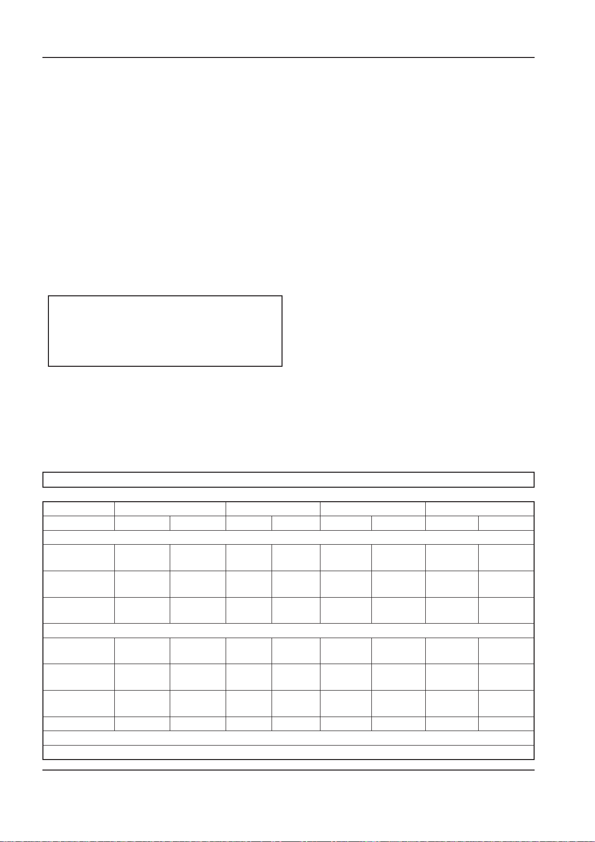
42 http://air.ingersollrand.com
MAINTENANCE OPERATION AND MAINTENANCE MANUAL
Clean the cooler.
SEPARATOR ELEMENT CHANGE PROCEDURE
Stop the machine, electrically isolate and vent all
1.
trapped pressure.
Loosen separator element with the correct tool.
2.
Remove the element from the housing; place it in
3.
a sealed bag and dispose of it safely.
Clean the mating face of the housing.
4.
Remove the new Ingersoll Rand replacement
5.
element from its protective package.
Apply a small amount of lubricant to the element
6.
seal.
Screw the new element down until the seal
7.
makes contact with the housing, then hand
tighten a further half turn.
Start the compressor and check for leaks.
8.
CAUTION
This unit is not designed or intended to operate
when contaminated with silicone. Lubricants,
greases or other items containing silicone
should not be used on this unit.
COOLER CLEANING PROCEDURE
Stop the machine, electrically isolate and vent all
1.
trapped pressure.
3.
Rebuild in reverse order.
4.
BELT CHECKING AND ADJUSTMENT PROCEDURE
Check belt tension occasionally, especially if looseness
is suspected. A quick check to determine if adjustment
is proper may be made by observing the slack side of
the belt for a slight bow when the unit is in operation.
If a slight bow is evident, the belt is usually adjusted
satisfactorily.
A belt tension measurement device can be used to
determine the tension of the belt.
Belt tensioning can be achieved by loosening the airend
anchor screws, a belt tensioning bolt is provided to aid
in moving the airend.
Follow the procedures outlined below to correctly set
and measure belt tension.
1. Lay a straight edge across the top outer surface of
the belt drive from pulley to sheave.
2. At the center of the span, perpendicular to the
belt, apply pressure to the outer surface of the
belt with a tension gauge. Force the belt to the
deection indicated in the table below, and
compare the reading on the tension gauge to the
gures shown.
Remove the top cover to obtain access to the
2.
cooler.
BELT TENSION
New Used New Used New Used New Used
60hz
125 psig 75 Lb
(34 Kg)
150 psig 75 Lb
(34 Kg)
210 psig 75 Lb
(34 Kg)
50hz
8 bar 85 Lb
(39 Kg)
10 bar 90 Lb
(41 Kg)
14.5 bar 90 Lb
(41 Kg)
5hp/4kw * 7.5hp/5.5kw * 10hp/7.5kw * 15hp/11kw **
62 Lb
(28 Kg)
62 Lb
(28 Kg)
62 Lb
(28 Kg)
70 Lb
(32 Kg)
75 Lb
(34 Kg)
75 Lb
(34 Kg)
110 Lb
(50 Kg)
90 Lb
(41 Kg)
90 Lb
(41 Kg)
85 Lb
(39 Kg)
85 Lb
(39 Kg)
100 Lb
(45 Kg)
90 Lb
(41 Kg)
75 Lb
(34 Kg)
75 Lb
(34 Kg)
70 Lb
(32 Kg)
70 Lb
(32 Kg)
80 Lb
(36 Kg)
110 Lb
(50 Kg)
110 Lb
(50 Kg)
110 Lb
(50 Kg)
110 Lb
(50 Kg)
120 Lb
(54 Kg)
120 Lb
(54 Kg)
90 Lb
(41 Kg)
90 Lb
(41 Kg)
90 Lb
(41 Kg)
90 Lb
(41 Kg)
100 Lb
(45 Kg)
100 Lb
(45 Kg)
140 Lb
(64 Kg)
140 Lb
(64 Kg)
150 Lb
(68 Kg)
140 Lb
(64 Kg)
140 Lb
(64 Kg)
150 Lb
(68 Kg)
120 Lb
(54 Kg)
120 Lb
(54 Kg)
125 Lb
(57 Kg)
120 Lb
(54 Kg)
120 Lb
(54 Kg)
125 Lb
(57 Kg)
* ”Krikit I” gauge or equal
** ”Krikit II” gauge or equal
Page 43
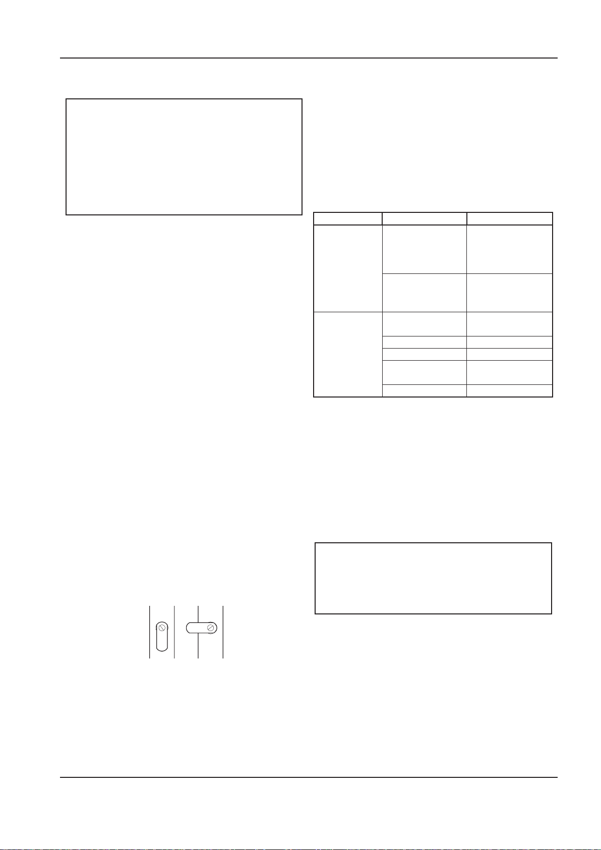
OPERATION AND MAINTENANCE MANUAL MAINTENANCE
Strainer Ball Valve.
OPEN CLOSED
Ensure the pulley and sheave are properly aligned and
the motor anchor screws are adequately retightened
prior to restarting the compressor.
cycles from 30 seconds to 45 minutes. The “time on”
setting determines the actual time the compressor
drains condensate.
CAUTION
Improper pulley/sheave alignment and belt
tension can result in motor overload, excessive
vibration, and premature belt and/or bearing
failure.
To prevent these problems from occurring,
ensure the pulley and sheave are aligned and
belt tension is satisfactory after installing new
belts or tensioning existing belts.
ELECTRIC DRAIN VALVE (OPTIONAL)
PRODUCT DESCRIPTION
The Electric Drain Valve removes condensed water and
oil from the air receiver tank. Additional drains may
be installed throughout your compressed air system,
including aftercoolers, lters, drip legs and dryers.
The Electric Drain Valve operates on a timer which can
be set to automatically drain the air receiver tank at
operator-determined intervals.
Key features include:
100% continuous duty
•
•
NEMA 4 enclosure
The timer’s cycle rate and drain opening time should
be adjusted to open just long enough to discharge the
condensate. The timer is properly set when it opens
and discharges condensate and then vents air for
approximately one second before closing. Adjustments
may be made depending on many factors, including
humidity and duty cycle.
TROUBLESHOOTING
TROUBLE CAUSE ACTION
Valve will not
close.
Timer will not
activate
MAINTENANCE
Debris in solenoid
valve prevents
diaphragm from
seating.
Short in electrical
component.
No electrical supply.
Timer malfunction Replace timer.
Clogged port. Clean valve.
Solenoid valve
malfunction.
Clogged strainer. Clean strainer.
Remove solenoid
valve, disassemble,
clean and reassemble.
Check and replace
power cord or
timer as needed.
Apply power.
Replace solenoid
valve.
•
Adjustable time on (0.5 - 10 seconds)
•
Adjustable time o (0.5 - 45 minutes)
•
Stainless steel operator
•
LED to indicate electrical power is on
•
LED to indicate valve is open
•
Manual override
OPERATION
Open the strainer ball valve.
1.
2. Set the “time o” and “time on” knobs. See TIMER
SETTINGS (below) for an explanation of the
settings.
3. During compressor operation, check for air leaks.
TIMER SETTINGS
The “time o” setting determines the interval between
Periodically clean the screen inside the valve to keep
the drain functioning at maximum capacity. To do this,
perform the following steps:
Close the strainer ball valve completely to isolate
1.
it from the air receiver tank.
Press the TEST button on the timer to vent the
2.
pressure remaining in the valve. Repeat until all
pressure is removed.
CAUTION
High pressure air can cause injury from
ying debris. Ensure the strainer ball valve is
completely closed and pressure is released from
the valve prior to cleaning.
3. Remove the plug from the strainer with a
suitable wrench. If you hear air escaping from
the cleaning port, STOP IMMEDIATELY and repeat
steps 1 and 2.
4. Remove the stainless steel lter screen and clean
it. Remove any debris that may be in the strainer
body before replacing the lter screen.
5. Replace plug and tighten with wrench.
6. When putting the Electric Drain Valve back into
service, press the TEST button to conrm proper
function.
http://air.ingersollrand.com 43
Page 44
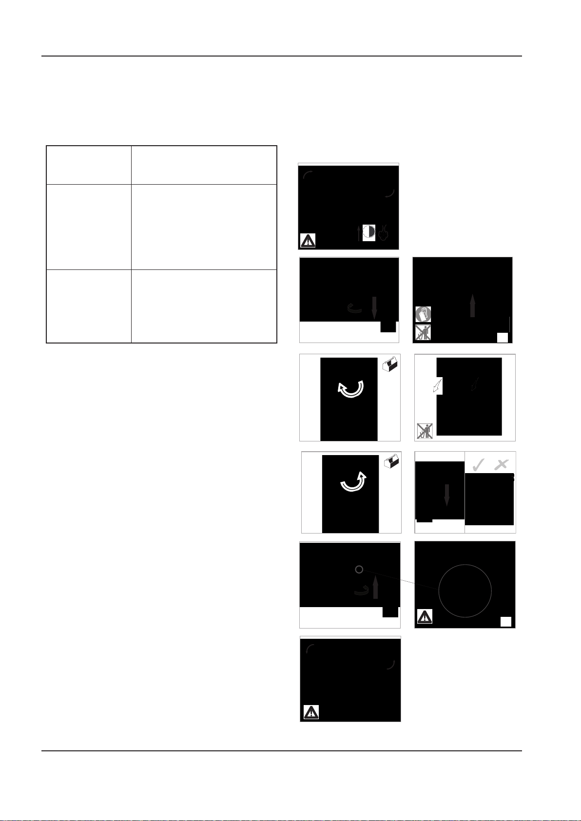
44 http://air.ingersollrand.com
MAINTENANCE OPERATION AND MAINTENANCE MANUAL
1
2
2
3
> 30s
4
5
0 bar
0 psi
1
2
0 bar
0 psi
7 8
0 bar
0 psi
9 10
2
1
0 bar
0 psi
0 bar
0 psi
1
2
12
5 6
1
Before accessing live electrical parts, disconnect the
AIR FILTER MAINTENANCE
power supply to the dryer using disconnect switch or
disconnect the cable connections.
In order to ensure optimum compressed air quality the
lter element should be replaced as follows. (Used lter
Preventive maintenance
For optimum performance from your dryer, follow the
periodic maintenance schedule described below.
WEEKLY CONDENSATE DRAINS
elements must be disposed of in accordance with local
regulations.)
Use only genuine Ingersoll Rand replacement
elements.
Verify that the condensate drains
are operating correctly.
EVERY 4 MONTHS CONDENSER
Remove any dust from the condenser ns.
COMPRESSOR
Make sure compressor power
consumption complies with data
YEARLY CONDENSATE DRAINS
plate specications.
Completely disassemble the
drains and clean all their components.
AIR FILTER
Replace air lter element.
MOISTURE SEPARATOR MAINTENANCE
The moisture separator will operate indenitely under
normal working conditions, however at some time
it may be necessary to replace the seals should the
housing leak.
Isolate the housing from the air supply.
1.
2.
3.
Fully depressurize in drain bowl as appropriate.
Unscrew bowl and remove. If pressure has not
been completely released from the housing,
air will escape from the warning hole giving
an audible alarm. Screw back bowl and repeat
instruction 2 before attempting again. Should
resistance to unscrewing be experienced,
provision is made for a ’C’ spanner to t onto the
ribs of the bowl.
Check condition of bowl seal and replace if
4.
necessary. Clean screw threads.
Ret bowl with ’O’ ring seal.
5.
Repressurize and check for leaks. If leaks occur
6.
they will most probably be from the bowl ’O’
ring. Depressurize housing and remove ’O’ ring as
stated above and inspect and clean. Ensure that
mating surfaces are clean and then ret ’O’ ring
and repressurize.
Page 45
OPERATION AND MAINTENANCE MANUAL MAINTENANCE
DISASSEMBLING THE UNIT
The unit has been designed and constructed to
guarantee continuous operation.
The long service life of some components such as the
fan and compressor depends on good maintenance.
The unit must only be disassembled by a refrigerant
specialist.
Refrigerant liquid and lubricating oil inside the
refrigeration circuit must be recovered in compliance
with current norms in the country where the machine is
installed.
RECYCLING DISASSEMBLY
Frame and panels Steel / epoxy resin polyester
Heat exchanger (cooler) Stainless steel
Pipes Copper
Insulation Gum synthetic
Compressor Steel / copper / aluminium
/ oil
Condenser Aluminium
Refrigerant R134a
Valve Steel
REFRIGERANT LEAKS IN THE REFRIGERATION
CIRCUIT
The unit is despatched in perfect working order, already
charged.
Refrigerant leaks may be identied by tripping of the
refrigeration overload protector.
IF A LEAK IS DETECTED IN THE REFRIGERANT CIRCUIT,
SEEK TECHNICAL ASSISTANCE.
REFRIGERANT CHARGING
THIS OPERATION MUST ONLY BE PERFORMED BY A
REFRIGERANT SPECIALIST.
WHEN REPAIRING THE REFRIGERANT CIRCUIT,
COLLECT ALL THE REFRIGERANT IN A CONTAINER
AND DISPOSE OF IT IN THE APPROPRIATE MANNER.
CHARACTERISTICS OF REFRIGERANT R134A
In normal temperature and pressure conditions the
above refrigerant is a colorless, class A1/A1 gas with TVL
value of 1000 ppm (ASHRAE classication).
If a refrigerant leak occurs, thoroughly air the room
before commencing work.
TROUBLESHOOTING
TROUBLE CAUSE ACTION
Solenoid
condensate
valve will
not close.
Drain timer
will not
operate.
Debris in solenoid
valve prevents
diaphragm from
seating.
Short in electrical
component.
No electrical supply. Apply power.
Timer malfunction Replace timer.
Clogged port. Clean valve.
Solenoid valve
malfunction.
Clogged strainer. Clean strainer.
Remove
solenoid valve,
disassemble,
clean and
reassemble.
Check and
replace power
cord or timer as
needed.
Replace
solenoid valve.
MAINTENANCE
Periodically clean the screen inside the valve to keep
the drain functioning at maximum capacity. To do this,
perform the following steps:
Close the strainer ball valve completely to isolate
1.
it from the air receiver tank.
Press the TEST button on the timer to vent the
2.
pressure remaining in the valve. Repeat until all
pressure is removed.
CAUTION
High pressure air can cause injury from
ying debris. Ensure the strainer ball valve is
completely closed and pressure is released from
the valve prior to cleaning.
3. Remove the plug from the strainer with a
suitable wrench. If you hear air escaping from
the cleaning port, STOP IMMEDIATELY and repeat
steps 1 and 2.
4. Remove the stainless steel lter screen and clean
it. Remove any debris that may be in the strainer
body before replacing the lter screen.
5. Replace plug and tighten with wrench.
6. When putting the Electric Drain Valve back into
service, press the TEST button to conrm proper
function.
http://air.ingersollrand.com 45
Page 46
TROUBLE SHOOTING OPERATION AND MAINTENANCE MANUAL
TROUBLE SHOOTING
PROBLEM CAUSE REMEDY
Compressor fails to
start
Machine shuts down
periodically
High current draw Compressor operating above rated
Low current draw Air lter contaminated. Change air lter.
High discharge
pressure
Low system air
pressure
High dewpoint Refrigeration compressor not supplied
Ice formation in dryer Low evaporator pressure. Check hot gas valve setting.
Mains power or Control voltage not
available.
Defective Star / Delta timer. § Change Star / Delta timer.
High airend temperature. Top up coolant.
Motor overload. § Set overload to correct value and switch to
Line voltage variation. § Ensure voltage does not drop below 10% on
pressure.
Separator cartridge contaminated. Change air lter, and separator element.
Low voltage. § Ensure voltage does not drop below 10% on
Unbalanced voltage. Correct incoming supply voltage.
Damaged airend. † Change Airend.
Compressor operating unloaded. Set pressure to correct rating for machine.
High voltage. Reduce site voltage to correct operating
Defective inlet valve. † Fit inlet valve service kit.
Defective or incorrect pressure switch
setting.
Blowdown valve defective. † Fit blowdown solenoid service kit.
Inlet valve malfunction. † Fit inlet valve service kit.
Separator cartridge contaminated. Fit new Separator element.
Incorrect pressure transducer setting Set pressure to correct rating for machine.
Minimum pressure valve malfunction. † Fit Minimum pressure valve service kit.
Blowdown valve defective. † Fit blowdown solenoid service kit.
Drive belt slipping. Fit new belt.
Air system leaks. † Fix leaks.
Inlet valve malfunction. † Fit inlet valve service kit.
System demand exceeds compressor
delivery.
Compressed air lters contaminated. Replace air lter elements.
power.
Condensate system malfunction. Check operation of drain valve.
Condenser dirty. Clean condenser and replace panel lter
§
Check incoming power supply.
§
Check the control circuit fuse.
§
Check the transformer secondary windings
for the control voltage.
manual reset.
start up and 6% running.
Set pressure to correct rating for machine.
start up and 6% running.
voltage.
Replace or set pressure to correct rating for
machine.
Reduce demand or install additional
compressor.
Check incoming power supply.
Check the dryer protection fuse.
Check auxiliary contact on main motor
contactor.
Check operation of condensate check valves.
element.
46 http://air.ingersollrand.com
Page 47
OPERATION AND MAINTENANCE MANUAL TROUBLE SHOOTING
PROBLEM CAUSE REMEDY
Compressor trips
due to over temperature
Excessive coolant
consumption
Excessive noise level Air system leaks. † Fix leaks.
Shaft seal leaking Defective shaft seal. † Fit Airend shaft seal kit.
Pressure relief valve
opens
Black residue on belt
guard/cooler box
Safety valve blows
when compressor
goes on load
Compressor operating above rated pressure.
Package pre–lter blocked. Clean / replace package pre–lter.
Cooler blocked. Clean cooler.
Missing or incorrectly tted enclosure
panels
Low coolant level. Top up coolant and check for leaks.
High ambient temperature. Re–site compressor.
Restricted cooling air ow. Ensure correct air ow to compressor.
Separator element leak. Fit new Separator element.
Blocked separator element drain. † Remove ttings and clean.
Compressor operating below rated pres-
sure.
Coolant system leak. † Fix leaks.
Airend defective. † Change Airend.
Belts Slipping. Replace belt and tensioner.
Motor defective. † Replace motor.
Loose components. † Retighten loose items.
Defective switch or incorrect pressure
switch setting.
Minimum pressure valve malfunction. † Fit Minimum pressure valve service kit.
Blowdown valve defective. † Fit blowdown solenoid service kit.
Inlet valve malfunction. † Fit inlet valve service kit.
Pressure relief valve defective. Check the setting of the pressure relief valve
Drive belt slipping. Replace belt and tensioner.
Pulleys misaligned. Re–align pulleys.
Worn pulleys. † Replace pulleys and belt.
Minimum pressure valve stuck closed. Strip minimum pressure valve, examine and
Safety valve faulty Check the setting of the safety valve and the
Set pressure to correct rating for machine.
Ensure that all enclosure panels are correctly
tted.
Set pressure to correct rating for machine.
Replace or set pressure to correct rating for
machine.
and the rated pressure.
repair if necessary.
rated pressure.
NOTES:
§ Must be carried out by a competent electrician.
† This work is recommended to be carried out only by an Ingersoll Rand authorized service technician.
CAUTION
LOW DEMAND APPLICATIONS
During periods of low demand, the compressor may not reach its normal operating temperature Sustained
operation at low demand can result in the build up of condensate in the coolant. If this situation occurs, the
lubricating characteristics of the coolant can be impaired which may lead to damage of the compressor.
THE COMPRESSOR SHOULD BE ALLOWED AMPLE LOADED RUNNING TIME OF ATLEAST 10 MINUTES PER
HOUR DURING NORMAL DAILY USE.
http://air.ingersollrand.com 47
Page 48

LOOK WHAT INGERSOLL RAND CAN DO FOR YOU!
Ecient Field Service
We maintain a highly trained sta of technicians
to service your equipment for preventive
maintenance, or to assist you should emergencies
ever occur.
Complete Repair Service
Our trained technicians will repair or overhaul
your equipment to factory specications,
using only genuine Ingersoll Rand parts.
Special Engineering Service
We can help you identify and solve your problems
by evaluating your needs and recommending
theproper equipment to give your maximum
eciency.
Spare Parts
By stocking genuine Ingersoll Rand spare
parts, we can help you avoid costly delays
or substituting inferior parts. Using genuine
Ingersoll Rand parts on you Ingersoll
Rand equipment will help to keep even
older equipment running in good-as-new
Complete Stock of Equipment
We carry a complete line of Ingersoll Rand
equipment and accessories designed to meet
any compressed air application. We are backed
by Ingersoll Rand’s prompt factory shipment to
ensure you on-time delivery.
condition.
A SUBSTITUTE IS NOT A REPLACEMENT!
Ensure you get peak performance and longevity out of your Ingersoll Rand product by insisting on genuine Ingersoll
Rand replacement parts and maintenance kits. Not only are the replacement parts made to precise dimensions and OEM-
specied metallurgy, but each part is backed by the Ingersoll Rand warranty. Your local Customer Center, Distributor, or
direct Ingersoll Rand salesperson will work with your to ensure you get the parts you need to do the job right. Equip your
machines with only the best Ingersoll Rand genuine parts.
NOTE: THE USE OF REPAIR PARTS OTHER THAN THOSE INCLUDED WITHIN THE INGERSOLL RAND COMPANY
APPROVED PARTS LIST MAY CREATE UNSAFE CONDITIONS OR MECHANICAL FAILURES OVER WHICH INGERSOLL
RAND COMPANY HAS NO CONTROL. INGERSOLL RAND COMPANY SHALL BEAR NO RESPONSIBILITY FOR
EQUIPMENT ON WHICH NON-APPROVED REPAIR PARTS ARE INSTALLED.
The manufacturer reserves the right to make changes or add improvements without notice and without incurring any
obligation to make such changes to products previously sold.
 Loading...