

Page 1
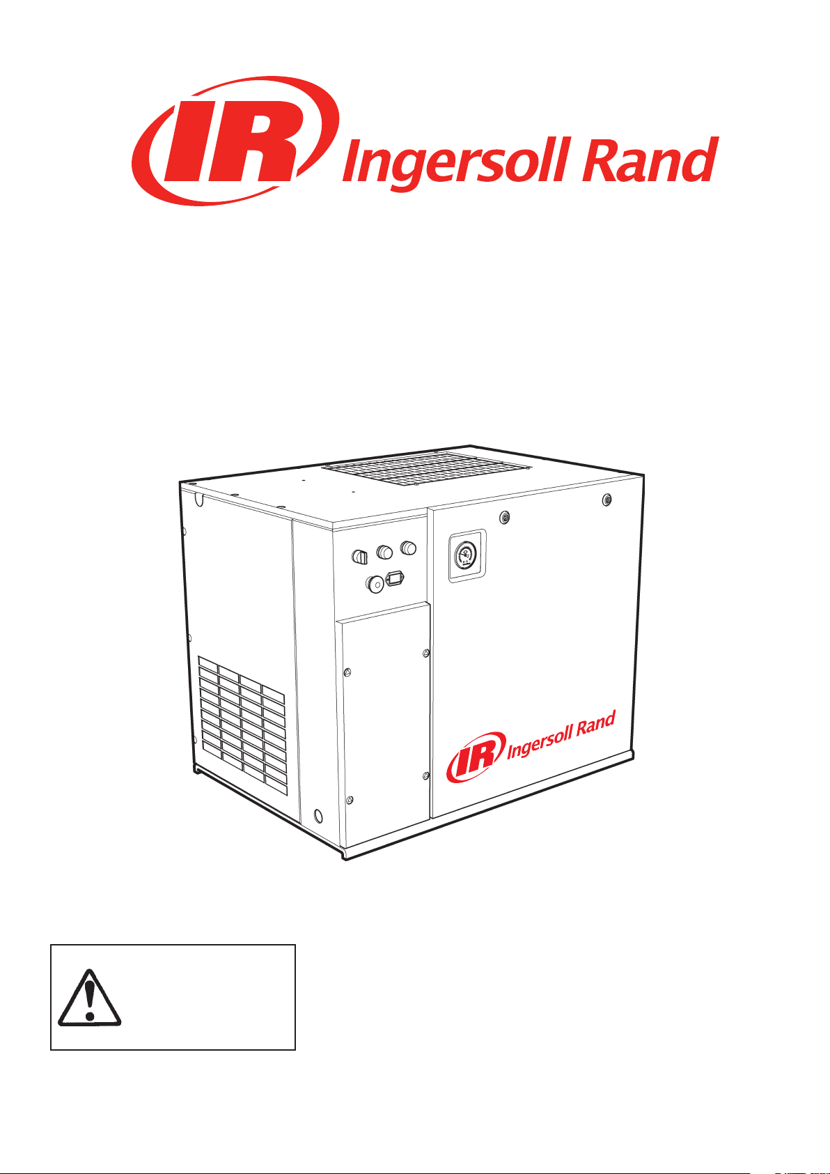
SSR UP5-4, UP5-5.5, UP5-7.5, UP5-11c
50 Hz
SSR UP6-5, UP6-7.5, UP6-10, UP6-15c
60 Hz
OPERATION AND MAINTENANCE MANUAL
This manual contains
important safety information
and must be made available
to personnel who operate
and maintain this machine.
Refer all communications to the nearest Ingersoll Rand Full Service Distributor.
C.C.N. : 80445273
REV. : A
DATE : OCTOBER 2008
Page 2
AIR COMPRESSOR GROUP
BONDED WARRANTY & REGISTERED START UP
Warranty
Note that this is Ingersoll Rand standard warranty. Any warranty in force at the time of purchase of the compressor or
negotiated as part of the purchase order may take precedence over this warranty.
Register on-line at http://air.ingersollrand.com
Ingersoll Rand
Industrial Air Solutions
Swan Lane
Hindley Green
Wigan WN2 4EZ
Ingersoll Rand Asia Pacic
C/O Ingersoll Rand South East Asia (Pte) Ltd.
42 Benoi Road
Singapore 629903
Ingersoll Rand
Industrial Air Solutions
P.O. Box 1840
800−D Beaty Street
Davidson, NC 28036
The Company warrants that the equipment manufactured by it and delivered hereunder will be free of defects in material and
workmanship for a period of twelve months from the date of placing the Equipment in operation or eighteen months from the
date of shipment from the factory, whichever shall rst occur. The Purchaser shall be obligated to promptly report any failure to
conform to this warranty, in writing to the Company in said period, whereupon the Company shall, at its option, correct such
nonconformity, by suitable repair to such equipment or, furnish a replacement part F.O.B. point of shipment, provided the
Purchaser has stored, installed, maintained and operated such Equipment in accordance with good industry practices and has
complied with specic recommendations of the Company. Accessories or equipment furnished by the Company, but manufactured by others, shall carry whatever warranty the manufacturers have conveyed to the Company and which can be passed on to
the Purchaser. The Company shall not be liable for any repairs, replacements, or adjustments to the Equipment or any costs of
labor performed by the Purchaser or others without Company‘s prior written approval.
The eects of corrosion, erosion and normal wear and tear are specically excluded. Performance warranties are limited to those
specically stated within the Company‘s proposal. Unless responsibility for meeting such performance warranties are limited to
specied tests, the Company‘s obligation shall be to correct in the manner and for the period of time provided above.
THE COMPANY MAKES NO OTHER WARRANTY OR REPRESENTATION OF ANY KIND WHATSOEVER, EXPRESSED OR IMPLIED,
EXCEPT THAT OF TITLE, AND ALL IMPLIED WARRANTIES OF MERCHANTABILITY AND FITNESS FOR A PARTICULAR PURPOSE, ARE
HEREBY DISCLAIMED.
Correction by the Company of nonconformities whether patent or latent, in the manner and for the period of time provided
above, shall constitute fullment of all liabilities of the Company for such nonconformities whether based on contract, warranty
negligence, indemnity, strict liability or otherwise with respect to or arising out of such Equipment.
The purchaser shall not operate Equipment which is considered to be defective, without rst notifying the Company in writing of
its intention to do so. Any such use of Equipment will be at Purchaser‘s sole risk and liability.
Page 3

Operation and Maintenance Manual Contents
CONTENTS
FOREWORD . . . . . . . . . . . . . . . . . . . . . . . . . . . . . . . . . . . . . . . . . . . . . . . 5
DECALS. . . . . . . . . . . . . . . . . . . . . . . . . . . . . . . . . . . . . . . . . . . . . . . . . . 6
ISO SYMBOLS . . . . . . . . . . . . . . . . . . . . . . . . . . . . . . . . . . . . . . . . . . . . 6
GRAPHIC FORM AND MEANING OF ISO SYMBOLS . . . . . . . . . . . . . . . . . . . 6
ANSI SYMBOLS . . . . . . . . . . . . . . . . . . . . . . . . . . . . . . . . . . . . . . . . . . . 8
GRAPHIC FORM AND MEANING OF ANSI SYMBOLS . . . . . . . . . . . . . . . . . . 8
SAFETY . . . . . . . . . . . . . . . . . . . . . . . . . . . . . . . . . . . . . . . . . . . . . . . . . . 11
General Information. . . . . . . . . . . . . . . . . . . . . . . . . . . . . . . . . . . . . . . . 11
Compressed air . . . . . . . . . . . . . . . . . . . . . . . . . . . . . . . . . . . . . . . . . . . 11
Materials . . . . . . . . . . . . . . . . . . . . . . . . . . . . . . . . . . . . . . . . . . . . . . . 12
Transport . . . . . . . . . . . . . . . . . . . . . . . . . . . . . . . . . . . . . . . . . . . . . . . 12
Electrical . . . . . . . . . . . . . . . . . . . . . . . . . . . . . . . . . . . . . . . . . . . . . . . 12
Condensate disposal . . . . . . . . . . . . . . . . . . . . . . . . . . . . . . . . . . . . . . . 12
GENERAL INFORMATION . . . . . . . . . . . . . . . . . . . . . . . . . . . . . . . . . . . . . . 13
PIPING AND INSTRUMENTATION . . . . . . . . . . . . . . . . . . . . . . . . . . . . . . . . 13
SCHEMATIC, ELECTRICAL UP6 5–15HP FV 3PH 60Hz DOL – U.S.A. . . . . . . . . . . . 15
SCHEMATIC, ELECTRICAL UP6 5–15HP SD 3PH 60Hz . . . . . . . . . . . . . . . . . . . 16
SCHEMATIC, ELECTRICAL UP6 5–15HP FV 1PH 60Hz - U.S.A. . . . . . . . . . . . . . . 17
SCHEMATIC, ELECTRICAL UP5 5–15HP FV 3PH 50Hz DOL . . . . . . . . . . . . . . . . 18
SCHEMATIC, ELECTRICAL UP5 5–15HP SD 3PH 50Hz . . . . . . . . . . . . . . . . . . . 19
INSTALLATION/HANDLING . . . . . . . . . . . . . . . . . . . . . . . . . . . . . . . . . . . . . 20
UNPACKING . . . . . . . . . . . . . . . . . . . . . . . . . . . . . . . . . . . . . . . . . . . . . 21
UP-SERIES TANK MOUNTED (80 GAL) . . . . . . . . . . . . . . . . . . . . . . . . . . . . . 22
UP-SERIES TANK MOUNTED (120 GAL) . . . . . . . . . . . . . . . . . . . . . . . . . . . . 24
UP-SERIES TANK MOUNTED (272 LITRES) . . . . . . . . . . . . . . . . . . . . . . . . . . 26
UP-SERIES TANK MOUNTED (500 LITRES) . . . . . . . . . . . . . . . . . . . . . . . . . . 28
LOCATION IN THE PLANT . . . . . . . . . . . . . . . . . . . . . . . . . . . . . . . . . . . . . 30
DISCHARGE PIPING . . . . . . . . . . . . . . . . . . . . . . . . . . . . . . . . . . . . . . . . 30
ELECTRICAL DATA . . . . . . . . . . . . . . . . . . . . . . . . . . . . . . . . . . . . . . . . . 35
OPERATING INSTRUCTIONS . . . . . . . . . . . . . . . . . . . . . . . . . . . . . . . . . . . . 36
GENERAL OPERATION . . . . . . . . . . . . . . . . . . . . . . . . . . . . . . . . . . . . . . . 36
COMPRESSOR CONTROLS . . . . . . . . . . . . . . . . . . . . . . . . . . . . . . . . . . . . 37
AUTOMATIC START & STOP CONTROL. . . . . . . . . . . . . . . . . . . . . . . . . . . . . 37
DUAL CONTROL. . . . . . . . . . . . . . . . . . . . . . . . . . . . . . . . . . . . . . . . . . . 37
PRIOR TO STARTING . . . . . . . . . . . . . . . . . . . . . . . . . . . . . . . . . . . . . . . . 38
STARTING . . . . . . . . . . . . . . . . . . . . . . . . . . . . . . . . . . . . . . . . . . . . . . 38
NORMAL/EMERGENCY STOPPING. . . . . . . . . . . . . . . . . . . . . . . . . . . . . . . 38
MAINTENANCE. . . . . . . . . . . . . . . . . . . . . . . . . . . . . . . . . . . . . . . . . . . . . 39
MAINTENANCE SCHEDULE. . . . . . . . . . . . . . . . . . . . . . . . . . . . . . . . . . . . 39
ROUTINE MAINTENANCE . . . . . . . . . . . . . . . . . . . . . . . . . . . . . . . . . . . . . 40
http://air.ingersollrand.com 3
Page 4

Contents Operation and Maintenance Manual
TOP UP COOLANT PROCEDURE . . . . . . . . . . . . . . . . . . . . . . . . . . . . . . . . . 41
COOLANT CHANGE PROCEDURE . . . . . . . . . . . . . . . . . . . . . . . . . . . . . . . . 41
COOLANT FILTER CHANGE PROCEDURE . . . . . . . . . . . . . . . . . . . . . . . . . . . 41
AIR FILTER ELEMENT CHANGE PROCEDURE . . . . . . . . . . . . . . . . . . . . . . . . . 41
SEPARATOR ELEMENT CHANGE PROCEDURE . . . . . . . . . . . . . . . . . . . . . . . . 42
COOLER CLEANING PROCEDURE . . . . . . . . . . . . . . . . . . . . . . . . . . . . . . . . 42
BELT CHECKING AND ADJUSTMENT PROCEDURE . . . . . . . . . . . . . . . . . . . . . 42
ELECTRIC DRAIN VALVE (OPTIONAL) . . . . . . . . . . . . . . . . . . . . . . . . . . . . . 43
PRODUCT DESCRIPTION . . . . . . . . . . . . . . . . . . . . . . . . . . . . . . . . . . . 43
OPERATION. . . . . . . . . . . . . . . . . . . . . . . . . . . . . . . . . . . . . . . . . . . . 43
TIMER SETTINGS . . . . . . . . . . . . . . . . . . . . . . . . . . . . . . . . . . . . . . . . 43
TROUBLESHOOTING . . . . . . . . . . . . . . . . . . . . . . . . . . . . . . . . . . . . . . 43
MAINTENANCE . . . . . . . . . . . . . . . . . . . . . . . . . . . . . . . . . . . . . . . . . 43
MOISTURE SEPARATOR MAINTENANCE . . . . . . . . . . . . . . . . . . . . . . . . . . . 44
AIR FILTER MAINTENANCE . . . . . . . . . . . . . . . . . . . . . . . . . . . . . . . . . . . . 44
DISASSEMBLING THE UNIT. . . . . . . . . . . . . . . . . . . . . . . . . . . . . . . . . . . . 45
REFRIGERANT LEAKS IN THE REFRIGERATION CIRCUIT . . . . . . . . . . . . . . . . . . 45
REFRIGERANT CHARGING . . . . . . . . . . . . . . . . . . . . . . . . . . . . . . . . . . . . 45
CHARACTERISTICS OF REFRIGERANT R134A . . . . . . . . . . . . . . . . . . . . . . . . 45
TROUBLESHOOTING. . . . . . . . . . . . . . . . . . . . . . . . . . . . . . . . . . . . . . . . 45
MAINTENANCE . . . . . . . . . . . . . . . . . . . . . . . . . . . . . . . . . . . . . . . . . . . 45
TROUBLE SHOOTING . . . . . . . . . . . . . . . . . . . . . . . . . . . . . . . . . . . . . . . . . 46
ABBREVIATIONS & SYMBOLS
#### Contact Ingersoll Rand for serial number
->#### Up to Serial No.
####-> From Serial No.
* Not illustrated
† Option
NR Not required
AR As required
SM Sitemaster/Sitepack
HA High ambient machine
WC Watercooled machine
AC Aircooled machine
ERS Energy recovery system
T.E.F.C. Totally enclosed fan cooled motor (IP54)
O.D.P. Open drip proof (motor)
ppm parts per million
4 http://air.ingersollrand.com
Page 5

OPERATION AND MAINTENANCE MANUAL FOREWORD
FOREWORD
The contents of this manual are considered to be
proprietary and condential to Ingersoll Rand and
should not be reproduced without the prior written
permission of Ingersoll Rand.
Nothing contained in this document is intended to
extend any promise, warranty or representation,
expressed or implied, regarding the Ingersoll Rand
products described herein. Any such warranties or other
terms and conditions of sale of products shall be in
accordance with the standard terms and conditions of
sale for such products, which are available upon request.
This manual contains instructions and technical data to
cover routine operation and scheduled maintenance
tasks by operation and maintenance sta. Major
overhauls are outside the scope of this manual and
should be referred to an authorised Ingersoll Rand
service department.
The design specication of this machine has been
certied as complying with E.C. directives. Any
modication to any part is absolutely prohibited and
would result in the CE certication and marking being
rendered invalid.
All components, accessories, pipes and connectors
added to the compressed air system should be:
of good quality, procured from a reputable
•
manufacturer and, wherever possible, be of a
type approved by Ingersoll Rand.
clearly rated for a pressure at least equal to the
•
machine maximum allowable working pressure.
compatible with the compressor lubricant/
•
coolant.
accompanied with instructions for safe
•
installation, operation and maintenance.
Details of approved equipment are available from
Ingersoll Rand Service departments.
The use of non-genuine spare repair parts other than
those included within the Ingersoll Rand approved
parts list may create hazardous conditions over which
Ingersoll Rand has no control. Therefore Ingersoll
Rand does not accept any liability for losses caused
by equipment in which non-approved repair parts are
installed. Standard warranty conditions may be aected.
Ingersoll Rand reserves the right to make changes and
improvements to products without notice and without
incurring any obligation to make such changes or add
such improvements to products sold previously.
The intended uses of this machine are outlined below
and examples of unapproved usage are also given,
however Ingersoll Rand cannot anticipate every
application or work situation that may arise.
IF IN DOUBT CONSULT SUPERVISION.
This machine has been designed and supplied for
use only in the following specied conditions and
applications:
Compression of normal ambient air containing
•
no known or detectable additional gases,
vapours. or particles
Operation within the ambient temperature
•
range specied in the GENERAL INFORMATION
section of this manual.
The use of the machine in any of the situation
types listed in table 1:-
Is not approved by Ingersoll Rand,
a.
May impair the safety of users and other
b.
persons, and
May prejudice any claims made against
c.
Ingersoll Rand.
TABLE 1
Use of the machine to produce compressed air for:
direct human consumption
a.
indirect human consumption, without
b.
suitable ltration and purity checks.
Use of the machine outside the ambient temperature
range specied in the GENERAL INFORMATION
SECTION of this manual.
Use of the machine where there is any actual or
foreseeable risk of hazardous levels of ammable
gases or vapours.
THIS MACHINE IS NOT INTENDED AND MUST NOT BE
USED IN POTENTIALLY EXPLOSIVE ATMOSPHERES,
INCLUDING SITUATIONS WHERE FLAMMABLE GASES
OR VAPOURS MAY BE PRESENT.
Use of the machine tted with non Ingersoll Rand
approved components.
Use of the machine with safety or control components
missing or disabled.
The company accepts no responsibility for errors in
translation of this manual from the original English
version.
© COPYRIGHT 2008
INGERSOLL RAND
http://air.ingersollrand.com 5
Page 6
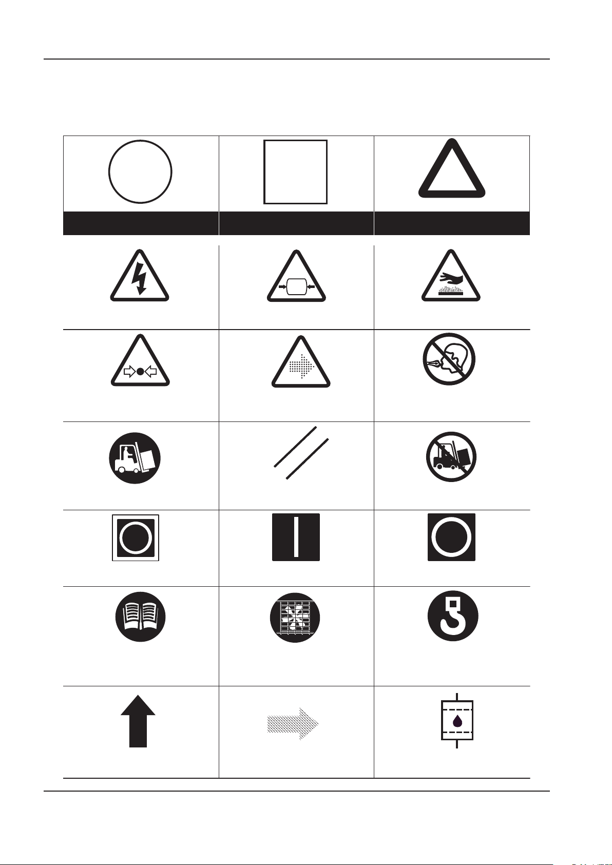
DECALS OPERATION AND MAINTENANCE MANUAL
Prohibition / Mandatory Information / Instructions Warning
WARNING: Electrical shock risk WARNING − Pressurised vessel. WARNING − Hot surface.
WARNING − Pressurised component or system. WARNING − Air/gas ow or Air discharge. Do not breathe the compressed air from this
machine.
Use fork lift truck from this side only. RESET Do not use fork lift truck from this side.
O (power).On (power).Emergency Stop.
Read the Operation and Maintenance manual
before operation or maintenance of this
machine is undertaken.
Do not operate the machine without the guard
being tted.
Lifting point.
ROTATION AIR DISCHARGE COOLANT FILTER
DECALS
ISO SYMBOLS
GRAPHIC FORM AND MEANING OF ISO SYMBOLS
6 http://air.ingersollrand.com
Page 7

OPERATION AND MAINTENANCE MANUAL DECALS
http://air.ingersollrand.com 7
Page 8
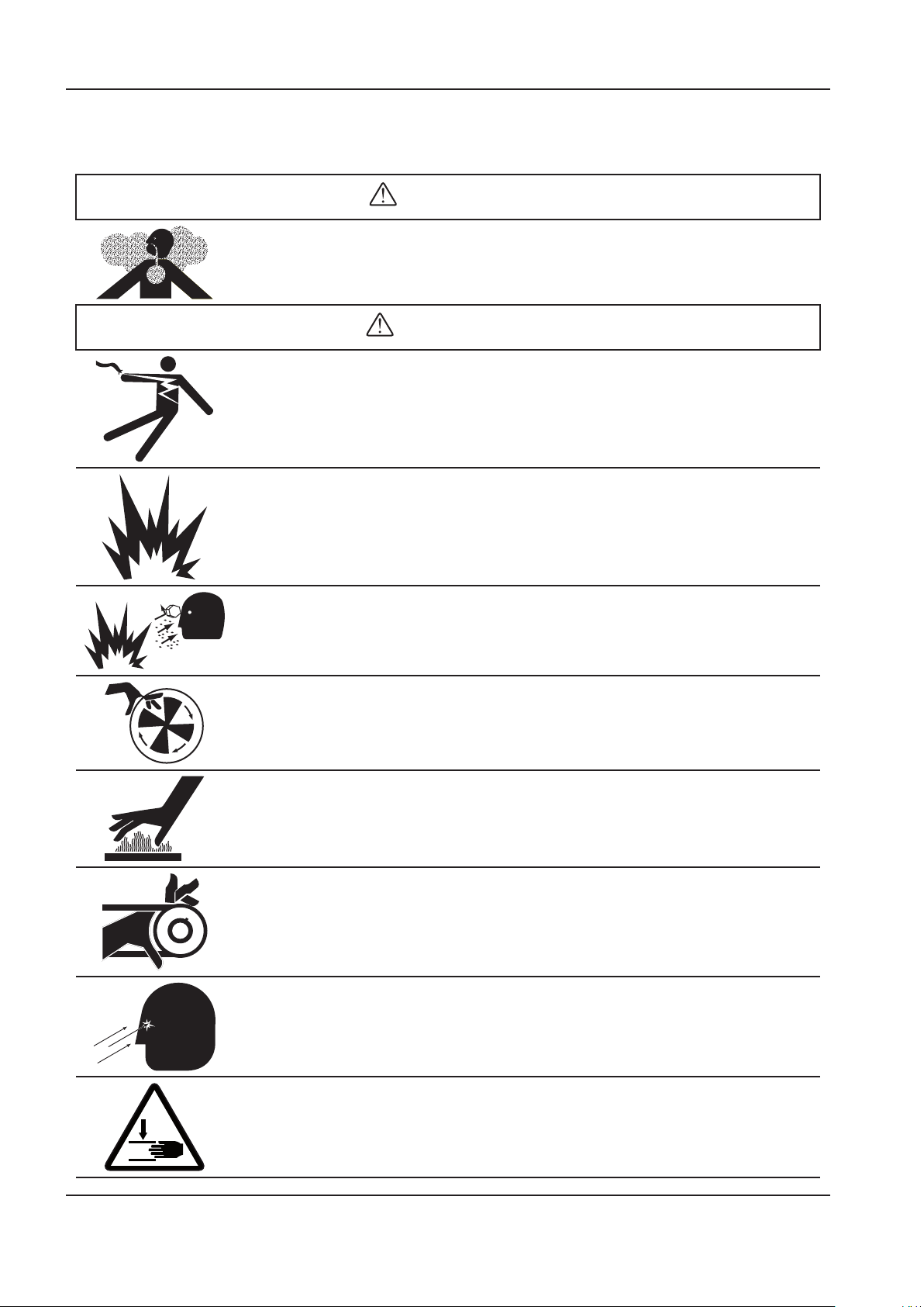
DECALS OPERATION AND MAINTENANCE MANUAL
DANGER
WARNING
ANSI SYMBOLS
GRAPHIC FORM AND MEANING OF ANSI SYMBOLS
INTAKE AIR. Can contain carbon monoxide or other contaminants. Will cause serious injury or
death. Ingersoll Rand air compressors are not designed, intended or approved for breathing air.
Compressed air should not be used for breathing air applications unless treated in accordance with
all applicable codes and regulations.
HAZARDOUS VOLTAGE. Can cause serious injury or death. Disconnect power and bleed pressure
from tank before servicing. Lockout/Tagout machine. Compressor must be connected to properly
grounded circuit. See Grounding Instructions in manual. Do not operate compressor in wet
conditions. Store indoors.
RISK OF FIRE OR EXPLOSION. Electrical arcing from compressor components can ignite ammable
liquids and vapors which can result in serious injury. Never operate the compressor near ammable
liquids or vapors. If used to spray ammable materials, keep compressor at least 20ft (6m) away
from the spray area.
HIGH PRESSURE AIR. Rusted tanks can cause explosion and severe injury or death. Receiver under
pressure. Operator should relieve tank pressure before performing maintenance. In addition to
automatic drain, operate manual drain valve weekly. Manual drain valve located at bottom of the
tank.
MOVING PARTS. Can cause serious injury. Do not operate with guards removed. Machine may start
automatically. Disconnect power before servicing. Lockout/Tagout machine.
HOT SURFACES. Can cause serious injury. Do not touch. Allow to cool before servicing.
Do not touch hot compressor or tubing.
EXPOSED MOVING BELTS AND SHEAVES.
Can cause severe injury or death.
Do not operate without guard in place. Disconnect power before servicing.
Lockout/Tagout machine.
Air ow exhaust may contain ying debris.
Safety protection should be worn at all times.
Pinch point hazard.
Keep hands clear.
8 http://air.ingersollrand.com
Page 9
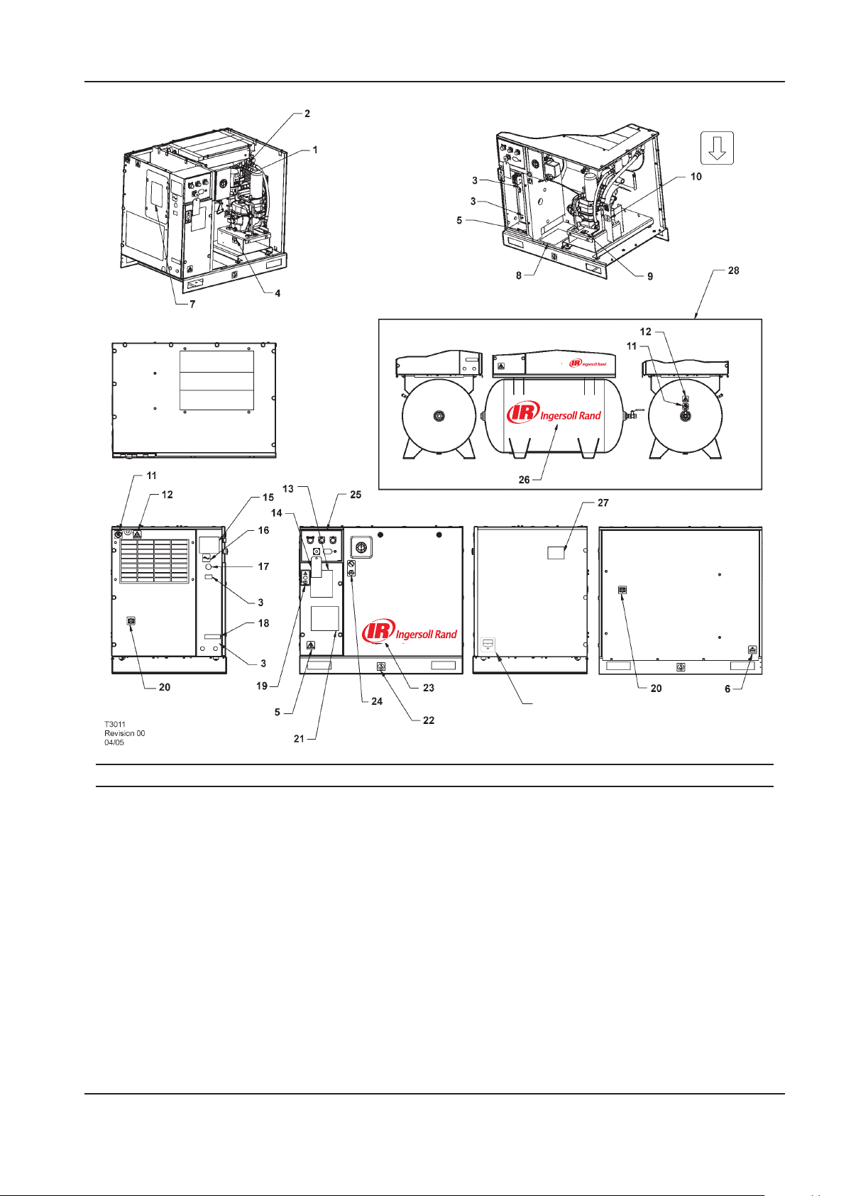
OPERATION AND MAINTENANCE MANUAL DECALS
29
Item ccn Qty. Description Item ccn Qty. Description
1 93166502 1 Decal, replacement element 12 92867498 1
2 92867530 1 Decal, warning hot surface
3 3 Decal, voltage 13 22547145 1 Decal, total air system
4 93166460 1 Decal, coolant drain Dryer packages only
5 92960593 2 Decal, warning hazardous 14 22459200 1 Tag, rotation
voltage 15 SPEC 1 Specications, compressor
6 93166478 1 Decal, condensate drain package
7 22530331 1 Decal, dryer bypass instruction 16 93166486 1 Decal, power inlet
8 23353196 1 Decal, maintenance parts 17 22141311 1 Decal, place to cover hole
9 92930585 1 Decal, pressurized vessel 18 22604276 1 Decal, multiple wiring circuit
10 93165983 1 Decal, rotation direction Dryer packages only
11 92867407 2 Decal, do not inhale 19 93493641 1 Decal, start up warning
Decal, notice air discharge
Base mount only
Contd....
http://air.ingersollrand.com 9
Page 10
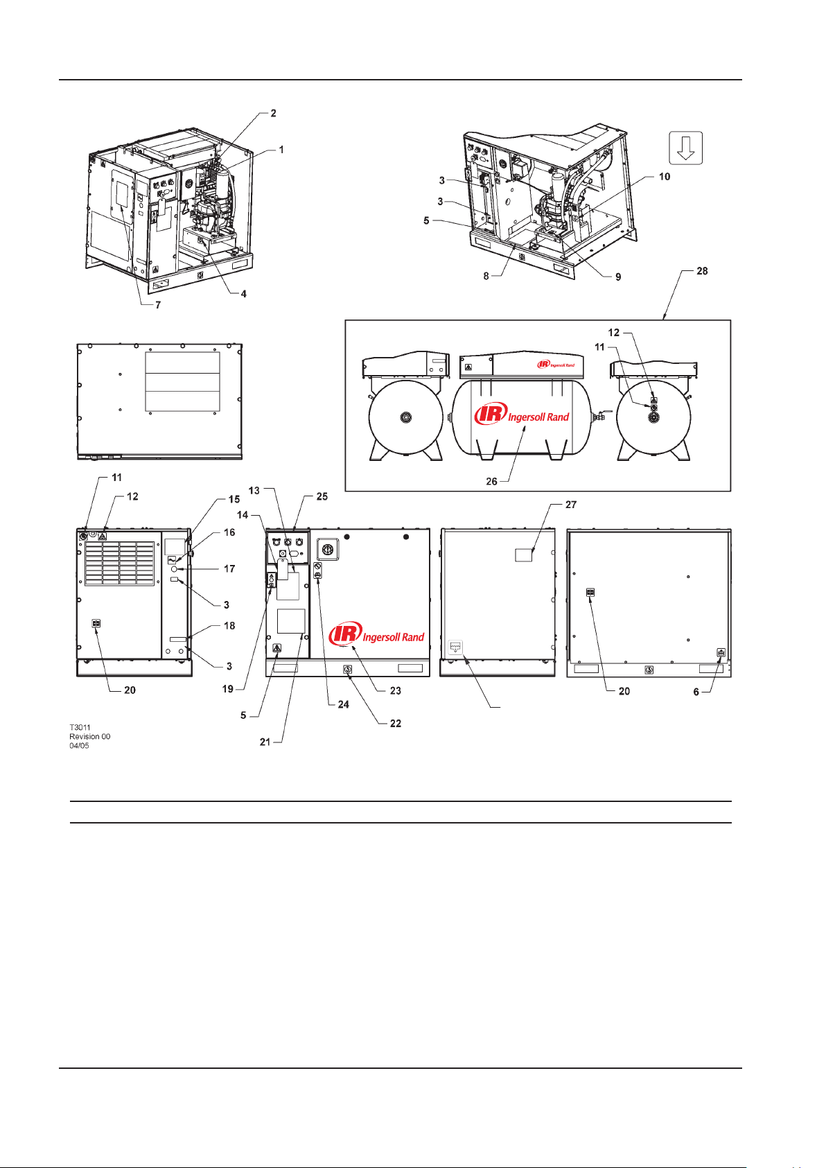
DECALS OPERATION AND MAINTENANCE MANUAL
29
Item ccn Qty. Description Item ccn Qty. Description
20 93165959 1 Decal, use guards when
running
21 1 Decal, wiring schematic
diagram
22 93171262 1 Decal, lift here both sides
Base mount only
23 22913032 1 Decal, Ingersoll Rand logo
Base mount only
22435713 1 Decal, Ingersoll Rand logo
Receiver mount only
24 92930668 1 Decal, no maintenance before
referring to manual
10 http://air.ingersollrand.com
25 22417109 1 Decal, facia
Rectangular hourmeter
22529291 1 Decal, facia
Round hourmeter
26 23038474 1 Decal, Ingersoll Rand logo
27 22454060 1 Decal, belt
28 Tank mount option
29 54618681 1 Decal, condensate drain
Page 11

OPERATION AND MAINTENANCE MANUAL SAFETY
SAFETY
DANGER
Hazard that WILL cause DEATH, SEVERE INJURY or
substantial property damage if ignored. Instructions
must be followed precisely to avoid injury or death.
WARNING
Hazard that CAN cause DEATH, SEVERE INJURY or
substantial property damage if ignored. Instructions
which must be followed precisely to avoid injury or
death.
CAUTION
Cautions call attention to instructions which must be
followed precisely to avoid damaging the product,
process or its surroundings.
NOTES
Notes are used for supplementary information.
BREATHING AIR PRECAUTION
Ingersoll Rand air compressors are not designed,
intended or approved for breathing air. Compressed
air should not be used for breathing air applications
unless treated in accordance with all applicable codes
and regulations.
GENERAL INFORMATION
Ensure that the operator reads and understands the
decals and consults the manuals before maintenance or
operation.
Ensure that the Operation and Maintenance manual is
not removed permanently from the machine.
Ensure that maintenance personnel are adequately
trained, competent and have read the Maintenance
Manuals.
Do not point air nozzles or sprayers toward anyone.
Compressed air and electricity can be dangerous.
Before undertaking any work on the compressor, ensure
that the electrical supply has been isolated and the
compressor has been relieved of all pressure.
Wear eye protection when operating or servicing
compressor.
All persons positioned near to operating machinery
should be equipped with hearing protection and given
instructions on its use in accordance with workplace
safety legislation.
Make sure that all protective covers are in place and that
the canopy/doors are closed during operation.
The specication of this machine is such that the
machine is not suitable for use in ammable gas risk
areas.
Installation of this compressor must be in accordance with
recognised electrical codes and any local Health and Safety
Codes.
The use of plastic bowls on line lters can be hazardous.
Their safety can be aected by either synthetic
lubricants, or the additives used in mineral oils.
Ingersoll Rand recommends that only lters with metal
bowls should be used on a pressurised system.
COMPRESSED AIR
Compressed air can be dangerous if incorrectly
handled. Before doing any work on the unit, ensure
that all pressure is vented from the system and that the
machine cannot be started accidentally.
WARNING
Imposing a normal or emergency stop on
the compressor will only relieve pressure
upstream of the minimum pressure valve
on top of the separator tank. If maintenance
work is required downstream of this
valve, ensure that all pressure is relieved
at the process vent point external to the
compressor.
Ensure that the machine is operating at the rated
pressure and that the rated pressure is known to all
relevant personnel.
All air pressure equipment installed in or connected to
the machine must have safe working pressure ratings of
at least the machine rated pressure.
If more than one compressor is connected to one
common downstream plant, eective isolation valves
must be tted and controlled by work procedures, so
that one machine cannot accidentally be pressurised /
over pressurised by another.
Compressed air must not be used for a direct feed to any
form of breathing apparatus or mask.
The discharged air contains a very small percentage
of compressor lubricant and care should be taken to
ensure that downstream equipment is compatible.
If the discharged air is to be ultimately released into a
conned space, adequate ventilation must be provided.
When using compressed air always use appropriate
personal protective equipment.
All pressure containing parts, especially exible hoses
and their couplings, must be regularly inspected, be free
from defects and be replaced according to the Manual
instructions.
Compressed air can be dangerous if incorrectly
handled. Before doing any work on the unit, ensure
that all pressure is vented from the system and that the
machine cannot be started accidentally.
Avoid bodily contact with compressed air.
All safety valves located in the separator tank must be
checked periodically for correct operation.
http://air.ingersollrand.com 11
Page 12

SAFETY OPERATION AND MAINTENANCE MANUAL
Do not over-pressurize the receiver tank or similar
vessels beyond design limits.
Do not use a receiver tank or similar vessels that fail
to meet the design requirements of the compressor.
Contact your distributor for assistance.
Do not drill into, weld or otherwise alter the receiver
tank or similar vessels.
Before servicing the unit, vent pressure before removing
the power to ensure that the gauge reads zero pressure.
MATERIALS
The following substances are used in the manufacture
of this machine and may be hazardous to health if used
incorrectly:
preservative grease
•
rust preventative
•
compressor coolant
•
AVOID INGESTION, SKIN CONTACT AND INHALATION
OF FUMES
TRANSPORT
WARNING
Any electrical connections or adjustments
should only be made by a suitably qualied
electrician
Close and lock all access doors when the compressor is
left unattended.
Do not use extinguishers intended for Class A or Class B
res on electrical res. Use only extinguishers suitable
for class BC or class ABC res.
Attempt repairs only in clean, dry, well lighted and
ventilated areas.
Connect the compressor only to electrical systems that
are compatible with its electrical characteristics and that
are within it’s rated capacity.
CONDENSATE DISPOSAL
As waste water regulations vary by country and region
it is the responsibility of the user to establish the
limitations and regulations in their particular area.
Ingersoll Rand and its associated distributors are happy
to advise and assist in these matters.
When loading or transporting machines ensure that the
specied lifting and tie down points are used.
Lifting equipment must be properly rated for the weight
of the compressor.
Do not work on or walk under the compressor while it is
suspended.
ELECTRICAL
Keep all parts of the body and any hand-held tools
or other conductive objects, away from exposed live
parts of the compressor electrical system. Maintain dry
footing, stand on insulating surfaces and do not contact
any other portion of the compressor when making
adjustments or repairs to exposed live parts of the
compressor electrical system.
For further information, consult Material Data Sheets for
ULTRA.
The above information contains data supplied in
support of United Kingdom Control of Substances
Hazardous to Health (C.O.S.H.H.) regulations.
12 http://air.ingersollrand.com
Page 13
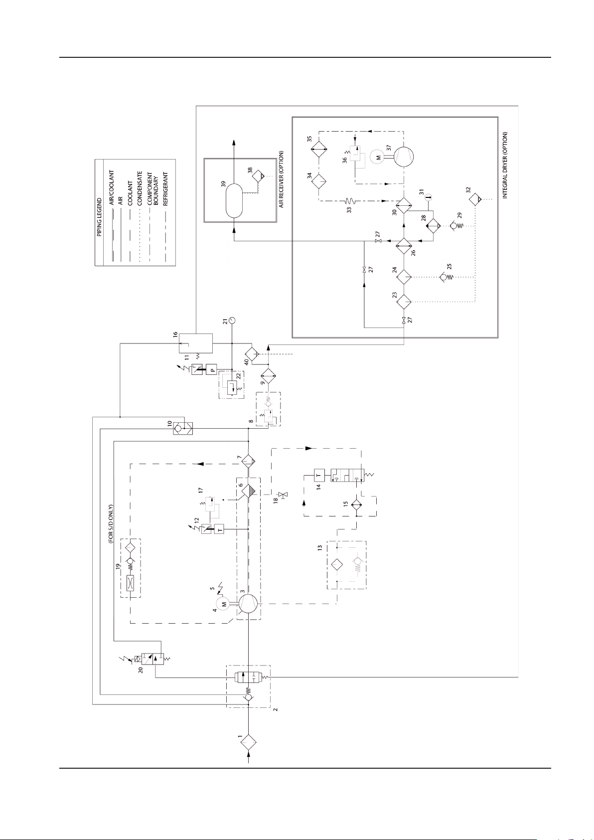
OPERATION AND MAINTENANCE MANUAL GENERAL INFORMATION
22426035
REV F
GENERAL INFORMATION
PIPING AND INSTRUMENTATION
http://air.ingersollrand.com 13
Page 14

14 http://air.ingersollrand.com
GENERAL INFORMATION OPERATION AND MAINTENANCE MANUAL
KEY
1 Filter, air 21 Gauge, pressure
2 Valve, air inlet 22 Valve, relief (sirc)
3 Air end assembly 23 Filter, general purpose air
4 Motor 24 Filter, high eciency air
5 Relay, motor overload 25 Valve, check
6 Tank, separator - coarse 26 Recuperator
7 Tank, separator - ne 27 Valve, isolation (option)
8 Valve, minimum pressure 28 Moisture separator
9 Aftercooler 29 Valve, check
10 Valve, blowdown 30 Evaporator
11 Switch, pressure 31 Indicator, dew point
12 Switch, temperature 32 Valve, condensate
13 Filter, coolant 33 Tube, capillary
14 Thermostat 34 Filter drier, refrigerant
15 Cooler, oil 35 Condenser
16 Valve, pilot 36 Valve, hot gas bypass
17 Valve, relief 37 Compressor, refrigerant
18 Valve, drain 38 Valve, auto drain
19 Screen, scavenge 39 Receiver, air
20 Valve, solenoid 40 Filter
Page 15
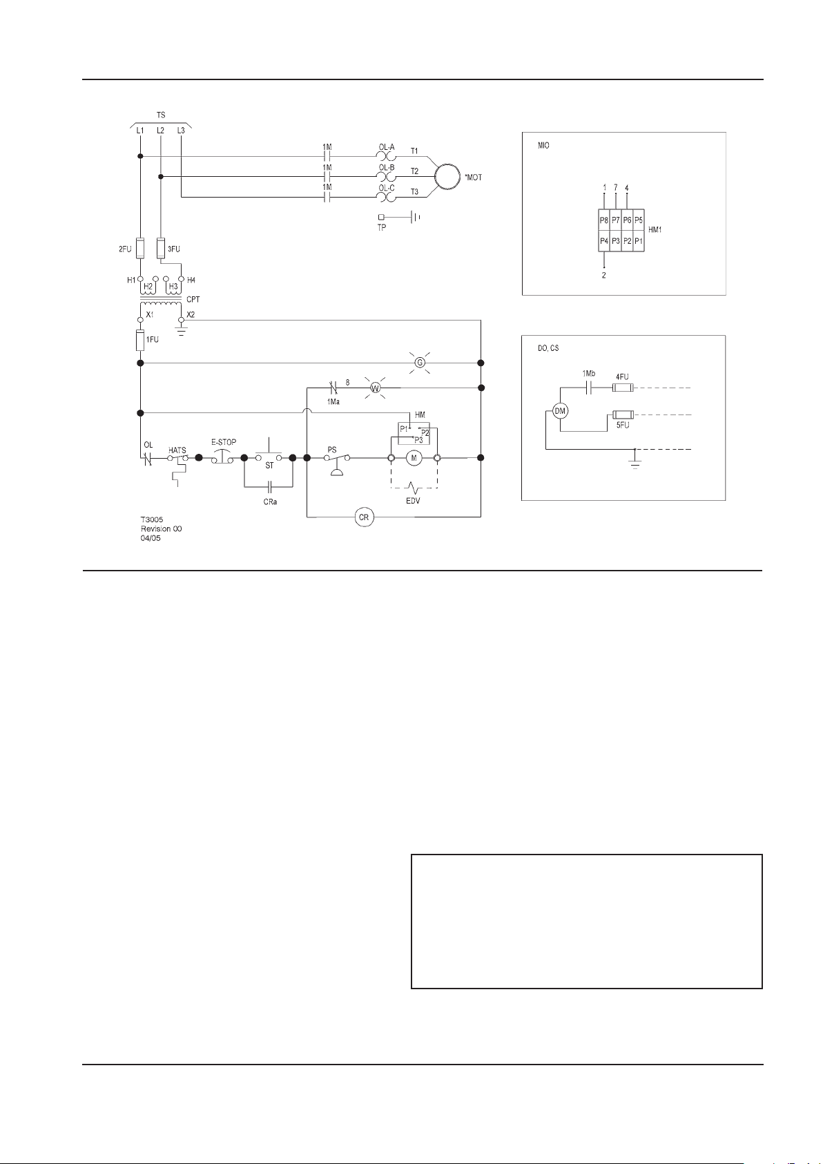
OPERATION AND MAINTENANCE MANUAL GENERAL INFORMATION
SCHEMATIC, ELECTRICAL UP6 5–15HP FV 3PH 60Hz DOL – U.S.A.
KEY
1FU,
2FU, 3FU
4FU, 5FU Fuse M Coil motor starter
1Ma Contact, auxiliary starter MIO Indicator, maintenance option
1Mb Contact, auxiliary starter MOT Motor
CPT Transformer, control
CR Relay, control PS Switch, pressure
CRa Contact, control relay ST Push button, start
CS Customer supplied 115v / 1 / 60hz TP Terminal points
DO Dryer option TS To supply
DM Motor, dryer W Standby light
EDV Valve, electric drain 120/1/50–60
E-STOP Button, emergency stop 1. (*) Furnished, mounted and wired outside of control
G Power on light 2. Circuit shown in normal position de–energized.
HM Hourmeter 3. All wiring to be marked in accordance with this
HM1 Indicator, maintenance 4. All wiring to be in accordance with NEC.
Fuse control circuit HATS Switch, high air temperature
(Instead of standard hourmeter)
OL Overload, motor starter
120/1/50–60
See transformer nameplate for wiring
connection requirements
NOTES
panel, if required by order.
schematic.
http://air.ingersollrand.com 15
Page 16
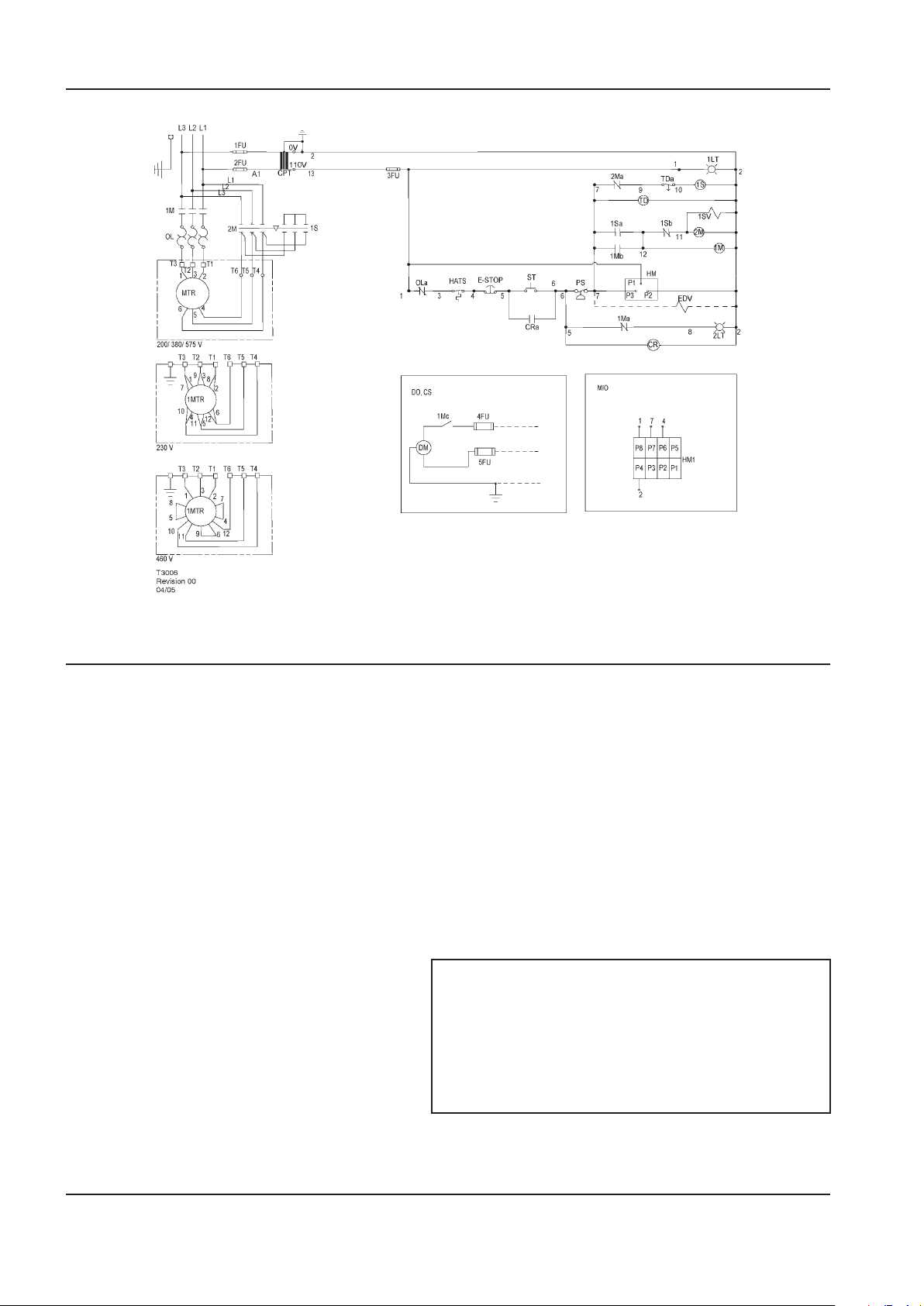
16 http://air.ingersollrand.com
GENERAL INFORMATION OPERATION AND MAINTENANCE MANUAL
SCHEMATIC, ELECTRICAL UP6 5–15HP SD 3PH 60Hz
KEY
1FU, 2FU Fuse, primary HATS Switch, high air temperature
3FU Fuse, secondary HM Hourmeter
4FU, 5FU Fuse, dryer HM1 Indicator, maintenance
1LT Light, power on indicator (green) MIO Indicator, maintenance option
(Instead of standard hourmeter)
2LT Light, auto restart indicator (white) MTR Motor, compressor
1M Contactor, main OL Overload, main motor
1Ma, b, c Contacts, auxiliary. Main contactor OLa Contact, main motor overload
2M Contactor, delta PS Switch, pressure
2Ma, b Contacts, auxiliary. Delta contactor ST Push button, start
1S Contactor, star T D Relay, delta starting (10sec)
1Sa, b Contacts, auxiliary. Star contactor TDc Relay, delay o, contact
1SV Valve, solenoid (nc)
CPT Transformer, control
CR Relay, control 1. (*) Furnished, mounted and wired outside of control
CRa Contact, control relay 2. Circuit shown in normal position de–energized.
CS Customer supplied 115v / 1 / 60hz 3. All wiring to be marked in accordance with this
DM Motor, dryer 4. All wiring to be in accordance with NEC.
DO Dryer option
EDV Valve, electric drain (optional)
E–STOP Switch, emergency stop
NOTES
panel, if required by order.
schematic.
Page 17
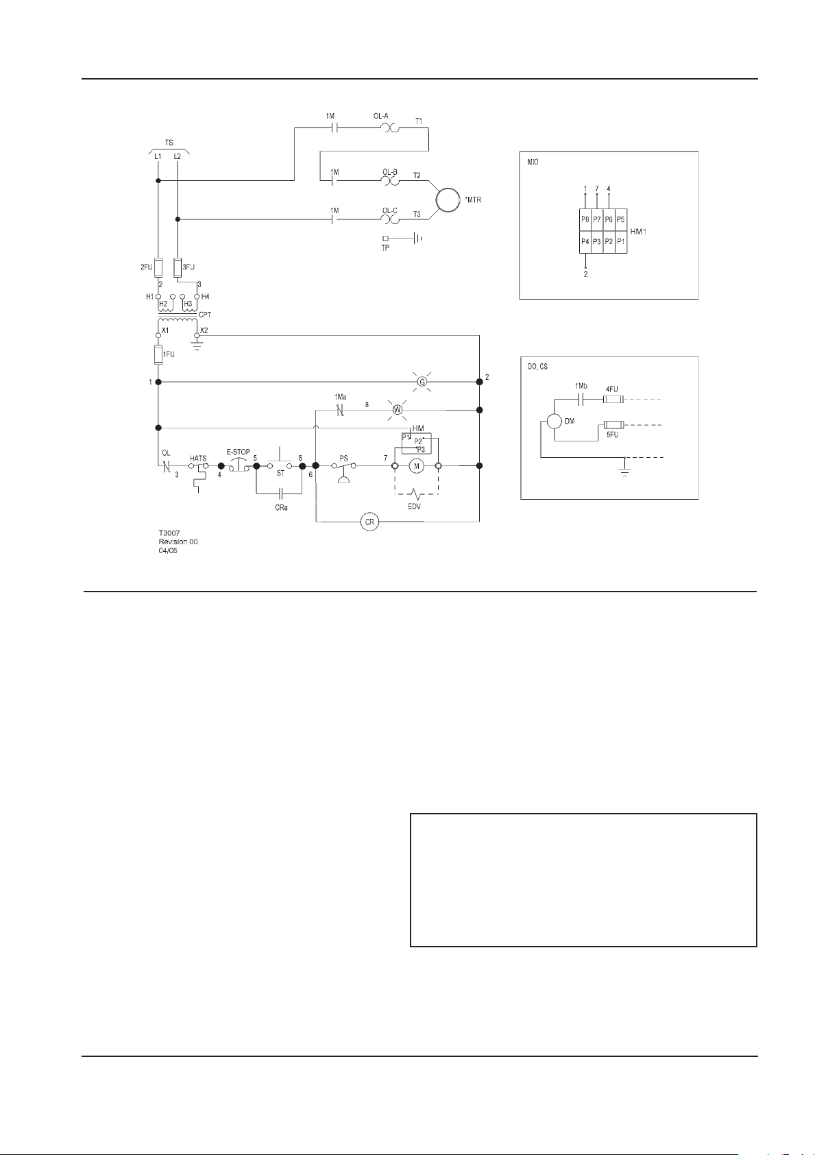
OPERATION AND MAINTENANCE MANUAL GENERAL INFORMATION
SCHEMATIC, ELECTRICAL UP6 5–15HP FV 1PH 60Hz - U.S.A.
KEY
1FU,
2FU, 3FU
4FU, 5FU Fuse, dryer MIO Indicator, maintenance option
1Ma Contact, auxiliary starter (Instead of standard hourmeter)
1Mb Contact, auxiliary starter MTR Motor,compressor
CPT Transformer, control 120/1/50–60 see OL Overload, motor starter
CR Relay, control TP Terminal points
CRa Contact, control relay TS To supply
CS Customer supplied 115v / 1 / 60hz W Standby light
DM Motor, dryer
DO Dryer option 1. (*) Furnished, mounted and wired outside of control
EDV Valve, electric drain 2. Circuit shown in normal position de–energized.
E-STOP Switch, emergency stop 3. All wiring to be marked in accordance with this
G Power on light 4. All wiring to be in accordance with NEC.
HM Hourmeter
HM1 Indicator, maintenance
Fuse control circuit M Coil motor starter
Transformer nameplate for wiring PS Switch, pressure
Connection requirements ST Push button, start
NOTES
panel, if required by order.
schematic.
http://air.ingersollrand.com 17
Page 18
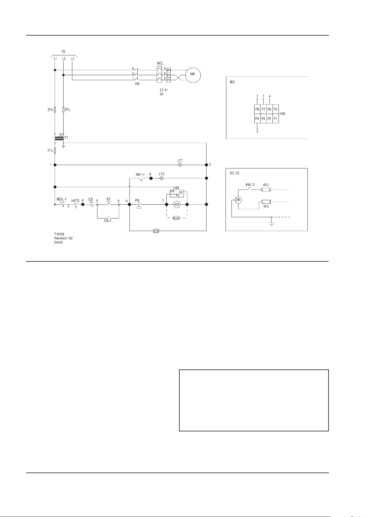
18 http://air.ingersollrand.com
GENERAL INFORMATION OPERATION AND MAINTENANCE MANUAL
SCHEMATIC, ELECTRICAL UP5 5–15HP FV 3PH 50Hz DOL
KEY
1FU Fuse, secondary MIO Indicator, maintenance option
(Instead of standard hourmeter)
2FU, 3FU Fuse, primary MM Motor, compressor
4FU, 5FU Fuse, dryer MOL Overload, main motor
CR Relay, control MOL-1 Contact, main motor overload
CS Customer supplied 230v / 1 / 50hz PS Switch, pressure
DM Motor, dryer ST Push button, start
DO Dryer option T1 Transformer, control
EDV Valve, electric drain TP Terminal points
ES Switch, emergency stop TS To supply
HATS Switch, high air temperature
HM Hourmeter
HM1 Indicator, maintenance
KM Contactor, main 1. (*) Furnished, mounted and wired outside of
KM–1,2 Contacts, auxiliary. Main contactor 2. Circuit shown in normal position de–energized.
LT1 Light, power on indicator (green) 3. All wiring to be marked in accordance with this
LT2 Light, auto restart indicator (white) 4. All wiring to be in accordance with NEC.
NOTES
control panel, if required by order.
schematic.
Page 19
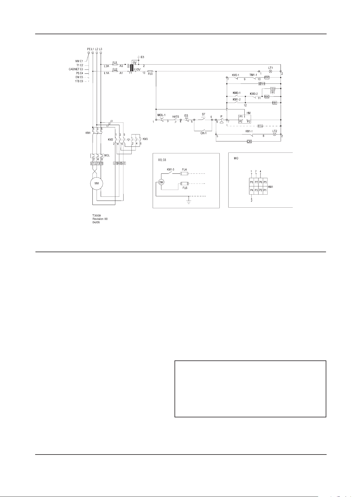
OPERATION AND MAINTENANCE MANUAL GENERAL INFORMATION
SCHEMATIC, ELECTRICAL UP5 5–15HP SD 3PH 50Hz
KEY
1SV Valve, solenoid (nc) KM2-1,2 Contacts, auxiliary. Delta contactor
CR Relay, control KM3 Contactor, star
CR-1 Contact, control relay KM3-1,2 Contacts, auxiliary. Star contactor
CS Customer supplied 230v / 1 / 50hz LT1 Light, power on indicator (green)
DM Motor, dryer LT2 Light, auto restart indicator (white)
DO Dryer option MIO Indicator, maintenance option
EDV Valve, electric drain (Instead of standard hourmeter)
HATS Switch, high air temperature MOL Overload, main motor
HM Hourmeter MOL-1 Contact, main motor overload
HM1 Indicator, maintenance ST Push button, start
MM Motor, compressor T1 Transformer, control
P Switch, pressure TM1 Relay, delta starting (10sec)
ES Switch, emergency stop TM1-1 Relay, delay o, contact
FU1, FU2 Fuse, primary
FU3 Fuse, secondary
FU4, FU5 Fuse, dryer 1. (*) Furnished, mounted and wired outside of
KM1 Contactor, main 2. Circuit shown in normal position de–energized.
KM-1,2,3 Contacts, auxiliary. Main contactor 3. All wiring to be marked in accordance with this
KM2 Contactor, delta 4. All wiring to be in accordance with NEC.
NOTES
control panel, if required by order.
schematic.
http://air.ingersollrand.com 19
Page 20
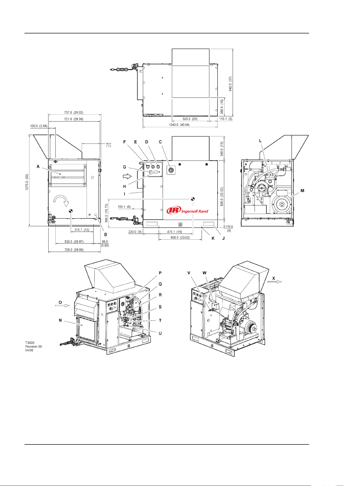
INSTALLATION / HANDLING OPERATION AND MAINTENANCE MANUAL
WITH
OPTIONAL
OUTDOOR MOD.
WITH
OPTIONAL
OUTDOOR MOD.
ROTATION
VIEW TOP
VIEW LEFT
VIEW RIGHT
VIEW FRONT
INSTALLATION/HANDLING
20 http://air.ingersollrand.com
Page 21

OPERATION AND MAINTENANCE MANUAL INSTALLATION / HANDLING
KEY
A Package pre-ller M Motor
B Hole, incoming power supply conduit N Integrated dryer (Optional)
C Gauge, pressure O Compressor and cooling air intake
D Yellow stand–by light P Filter, coolant
E Green power–on light Q Cartridge, coolant separator
F Green start push button R Valve, airend relief
G Emergency stop button S Plug, coolant ller
H Hourmeter T Sight–glass
I Starter box U Plug, coolant drain
J Lifting points V Valve, pilot
K Mounting holes (4 x 14.0mm [0.550”] diameter) W Switch, pressure
L Filter, air inlet X Cooling air exhaust
NOTES
1. Foundation or oor must be level and support all
mounting bolt locations equally. If necessary, shim
or grout the fourth bolt location.
2. Foundation bolts should protect thru nuts a
minimum of 13mm (0.50”) to allow for levelling.
3. Allow a minimum clearance of 1100mm (42”) on
the front and 920mm (36”) on the top, left right
and rear of the package for proper air circulation
and serviceability.
4. Approximate package weight: 298kg (655lbs).
5. External piping shall not exert any unresolved
moments or forces on the unit. Use pipe size as
large or larger at discharge connection.
6. There should be no plastic or pvc piping attached
to this unit or used for any lines downstream.
7. Do not pipe into a common header with a
reciprocating compressor, unless the reciprocating
compressor utilizes a discharge pulsation damper.
8. Sizing of electrical components not supplied
by Ingersoll Rand is the responsibility of the
customer and should be done in accordance with
the information on the compressor data plate and
national and local electrical codes.
All dimensions are in millimetres (inches) unless
otherwise stated.
Ensure that the correct fork lift truck slots or marked
lifting points are used whenever the machine is lifted or
transported.
UNPACKING
The compressor will normally be delivered with a
polythene cover. If a knife has to be used to remove
this cover ensure that the exterior paintwork of the
compressor is not damaged.
Ensure that all transport and packing materials are
discarded in a manner prescribed by local codes.
NOTE
http://air.ingersollrand.com 21
Page 22
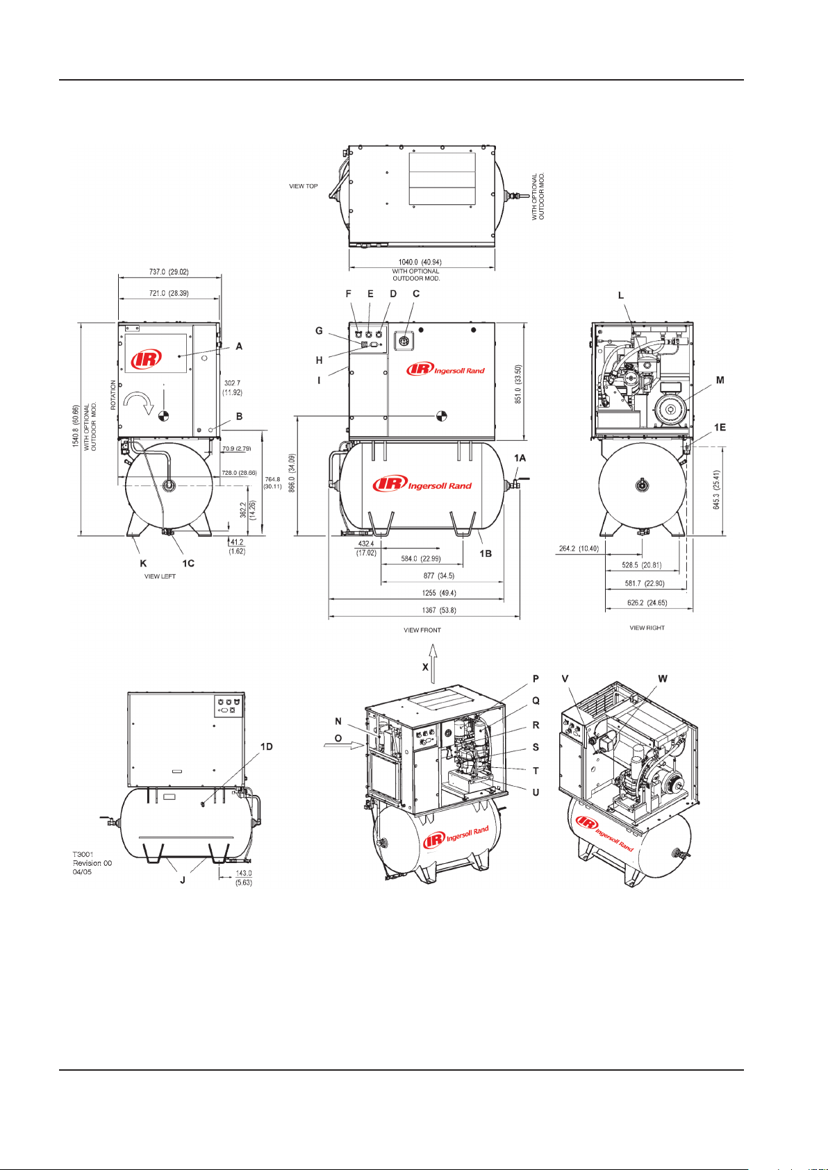
INSTALLATION / HANDLING OPERATION AND MAINTENANCE MANUAL
UP-SERIES
TANK MOUNTED (80 GAL)
22 http://air.ingersollrand.com
Page 23

OPERATION AND MAINTENANCE MANUAL INSTALLATION / HANDLING
KEY
A Package pre-ller P Filter, coolant
B Hole, incoming power supply conduit Q Cartridge, coolant separator
C Gauge, pressure R Valve, airend relief
D Yellow stand–by light S Plug, coolant ller
E Green power–on light T Sight–glass
F Green start push button U Plug, coolant drain
G Emergency stop button V Valve, pilot
H Hourmeter W Switch, pressure
I Starter box X Cooling air exhaust
J Lifting points 1A Valve, ball 0.75” N.P.T.
K Mounting holes (4 x 17.5mm [0.68”] x 44.5mm
[1.75”] slots)
L Filter, air inlet 1C Location for manual receiver drain
M Motor 1D Valve, receiver relief
N Integrated dryer (Optional) 1E 0.25” discharge port for optional electric drain valve
O Compressor and cooling air intake
1B Air receiver (Ø 620.0mm x 1168.4mm LG) ( Ø 24.40”
x 46.00” LG)
NOTES
1. Foundation or oor must be level and support all
mounting bolt locations equally. If necessary, shim
or grout the fourth bolt location.
2. Foundation bolts should protect thru nuts a
minimum of 13mm (0.50”) to allow for levelling.
3. Allow a minimum clearance of 1100mm (42”) on
the front and 920mm (36”) on the top, left right
and rear of the package for proper air circulation
and serviceability.
4. Approximate package weight: 420kg (925lbs).
5. External piping shall not exert any unresolved
moments or forces on the unit. Use pipe size as
large or larger at discharge connection.
6. There should be no plastic or pvc piping attached
to this unit or used for any lines downstream.
7. Do not pipe into a common header with a
reciprocating compressor, unless the reciprocating
compressor utilizes a discharge pulsation damper.
8. Sizing of electrical components not supplied
by Ingersoll Rand is the responsibility of the
customer and should be done in accordance with
the information on the compressor data plate and
national and local electrical codes.
NOTE
All dimensions are in millimetres (inches) unless
otherwise stated.
Ensure that the correct fork lift truck slots or marked
lifting points are used whenever the machine is lifted or
transported.
UNPACKING
The compressor will normally be delivered with a
polythene cover. If a knife has to be used to remove
this cover ensure that the exterior paintwork of the
compressor is not damaged.
Ensure that all transport and packing materials are
discarded in a manner prescribed by local codes.
http://air.ingersollrand.com 23
Page 24
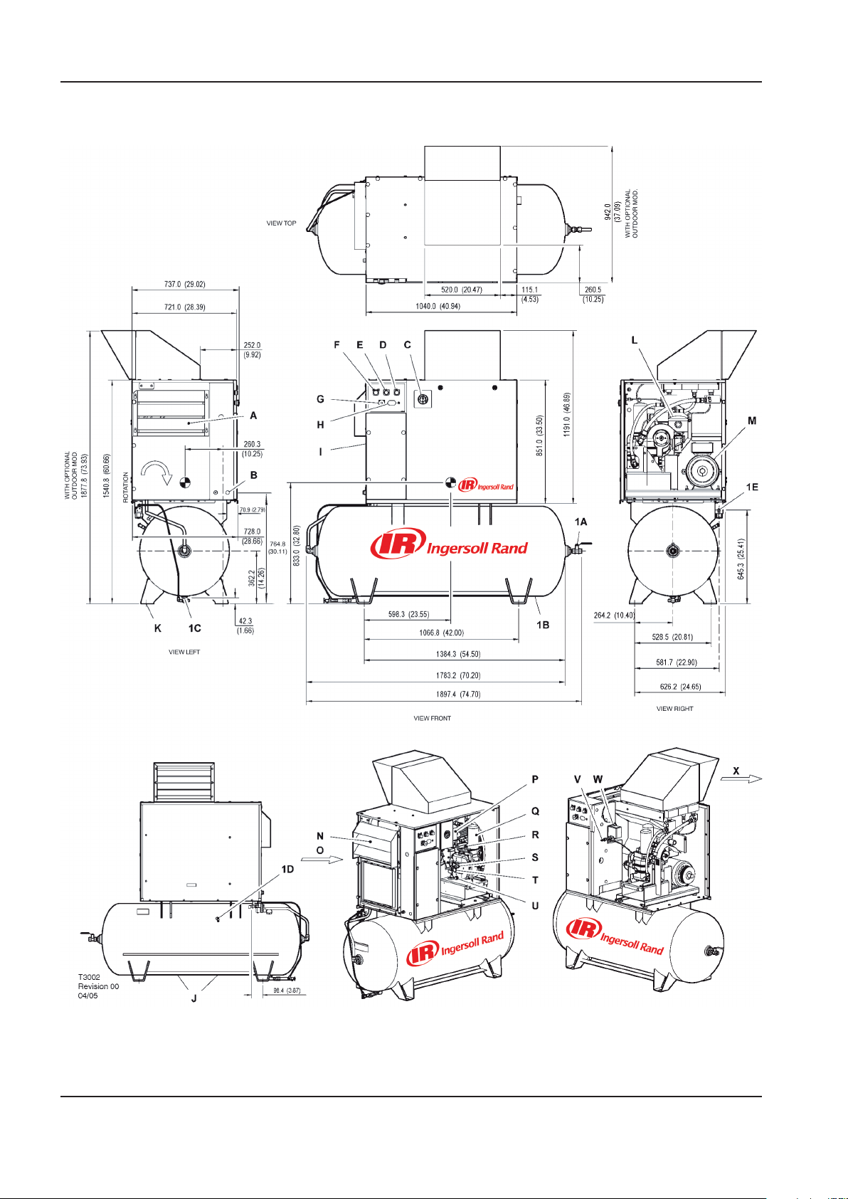
INSTALLATION / HANDLING OPERATION AND MAINTENANCE MANUAL
UP-SERIES
TANK MOUNTED (120 GAL)
24 http://air.ingersollrand.com
Page 25

OPERATION AND MAINTENANCE MANUAL INSTALLATION / HANDLING
KEY
A Package pre-ller P Filter, coolant
B Hole, incoming power supply conduit Q Cartridge, coolant separator
C Gauge, pressure R Valve, airend relief
D Yellow stand–by light S Plug, coolant ller
E Green power–on light T Sight–glass
F Green start push button U Plug, coolant drain
G Emergency stop button V Valve, pilot
H Hourmeter W Switch, pressure
I Starter box X Cooling air exhaust
J Lifting points 1A Valve, ball 0.75” N.P.T.
K Mounting holes (4 x 17.5mm [0.68”] x 44.5mm
[1.75”] slots)
L Filter, air inlet 1C Location for manual receiver drain
M Motor 1D Valve, receiver relief
N Integrated dryer (Optional) 1E 0.25” discharge port for optional electric drain valve
O Compressor and cooling air intake
1B Air receiver (Ø 618.0mm x 1701.0mm LG) ( Ø 24.33”
x 67.00” LG)
NOTES
1. Foundation or oor must be level and support all
mounting bolt locations equally. If necessary, shim
or grout the fourth bolt location.
2. Foundation bolts should protect thru nuts a
minimum of 13mm (0.50”) to allow for levelling.
3. Allow a minimum clearance of 1100mm (42”) on
the front and 920mm (36”) on the top, left right
and rear of the package for proper air circulation
and serviceability.
4. Approximate package weight: 430kg (946lbs).
5. External piping shall not exert any unresolved
moments or forces on the unit. Use pipe size as
large or larger at discharge connection.
6. There should be no plastic or pvc piping attached
to this unit or used for any lines downstream.
7. Do not pipe into a common header with a
reciprocating compressor, unless the reciprocating
compressor utilizes a discharge pulsation damper.
8. Sizing of electrical components not supplied
by Ingersoll Rand is the responsibility of the
customer and should be done in accordance with
the information on the compressor data plate and
national and local electrical codes.
NOTE
All dimensions are in millimetres (inches) unless
otherwise stated.
Ensure that the correct fork lift truck slots or marked
lifting points are used whenever the machine is lifted or
transported.
UNPACKING
The compressor will normally be delivered with a
polythene cover. If a knife has to be used to remove
this cover ensure that the exterior paintwork of the
compressor is not damaged.
Ensure that all transport and packing materials are
discarded in a manner prescribed by local codes.
http://air.ingersollrand.com 25
Page 26
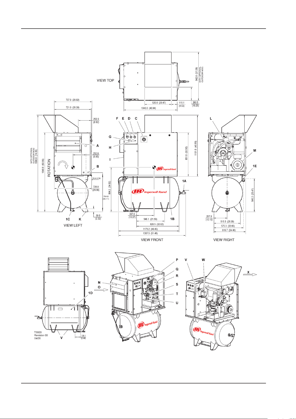
INSTALLATION / HANDLING OPERATION AND MAINTENANCE MANUAL
UP-SERIES
TANK MOUNTED (272 LITRES)
26 http://air.ingersollrand.com
Page 27

OPERATION AND MAINTENANCE MANUAL INSTALLATION / HANDLING
KEY
A Package pre-ller P Filter, coolant
B Hole, incoming power supply conduit Q Cartridge, coolant separator
C Gauge, pressure R Valve, airend relief
D Yellow stand–by light S Plug, coolant ller
E Green power–on light T Sight–glass
F Green start push button U Plug, coolant drain
G Emergency stop button V Valve, pilot
H Hourmeter W Switch, pressure
I Starter box X Cooling air exhaust
J Lifting points 1A Valve, ball 0.75” N.P.T.
K Mounting holes (4 x 17.5mm [0.68”] x 44.5mm
[1.75”] slots)
L Filter, air inlet 1C Location for manual receiver drain
M Motor 1D Valve, receiver relief
N Integrated dryer (Optional) 1E 0.25” discharge port for optional electric drain valve
O Compressor and cooling air intake
1B Air receiver ( Ø 600.0mm x 1111.0mm LG) ( Ø 23.62”
x 43.74” LG)
NOTES
1. Foundation or oor must be level and support all
mounting bolt locations equally. If necessary, shim
or grout the fourth bolt location.
2. Foundation bolts should protect thru nuts a
minimum of 13mm (0.50”) to allow for levelling.
3. Allow a minimum clearance of 1100mm (42”) on
the front and 920mm (36”) on the top, left right
and rear of the package for proper air circulation
and serviceability.
4. Approximate package weight: 400kg (880lbs).
5. External piping shall not exert any unresolved
moments or forces on the unit. Use pipe size as
large or larger at discharge connection.
6. There should be no plastic or pvc piping attached
to this unit or used for any lines downstream.
7. Do not pipe into a common header with a
reciprocating compressor, unless the reciprocating
compressor utilizes a discharge pulsation damper.
8. Sizing of electrical components not supplied
by Ingersoll Rand is the responsibility of the
customer and should be done in accordance with
the information on the compressor data plate and
national and local electrical codes.
NOTE
All dimensions are in millimetres (inches) unless
otherwise stated.
Ensure that the correct fork lift truck slots or marked
lifting points are used whenever the machine is lifted or
transported.
UNPACKING
The compressor will normally be delivered with a
polythene cover. If a knife has to be used to remove
this cover ensure that the exterior paintwork of the
compressor is not damaged.
Ensure that all transport and packing materials are
discarded in a manner prescribed by local codes.
http://air.ingersollrand.com 27
Page 28
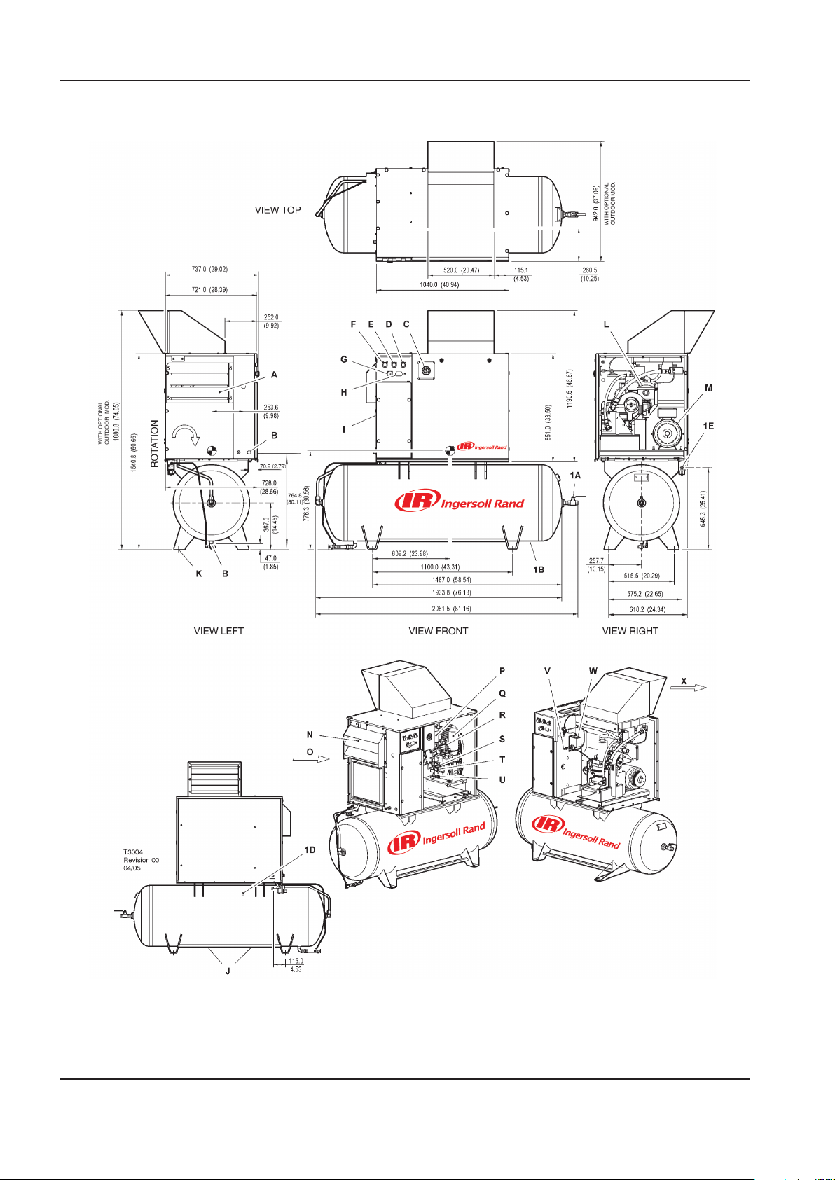
INSTALLATION / HANDLING OPERATION AND MAINTENANCE MANUAL
UP-SERIES
TANK MOUNTED (500 LITRES)
28 http://air.ingersollrand.com
Page 29

OPERATION AND MAINTENANCE MANUAL INSTALLATION / HANDLING
KEY
A Package pre-ller P Filter, coolant
B Hole, incoming power supply conduit Q Cartridge, coolant separator
C Gauge, pressure R Valve, airend relief
D Yellow stand–by light S Plug, coolant ller
E Green power–on light T Sight–glass
F Green start push button U Plug, coolant drain
G Emergency stop button V Valve, pilot
H Hourmeter W Switch, pressure
I Starter box X Cooling air exhaust
J Lifting points 1A Valve, ball 0.75” N.P.T.
K Mounting holes (4 x 17.5mm [0.68”] x 44.5mm
[1.75”] slots)
L Filter, air inlet 1C Location for manual receiver drain
M Motor 1D Valve, receiver relief
N Integrated dryer (Optional) 1E 0.25” discharge port for optional electric drain
O Compressor and cooling air intake
1B Air receiver (Ø 610.0mm x 1866.0mm LG) ( Ø 24.02”
x 73.46” LG)
valve
NOTES
1. Foundation or oor must be level and support all
mounting bolt locations equally. If necessary, shim
or grout the fourth bolt location.
2. Foundation bolts should protect thru nuts a
minimum of 13mm (0.50”) to allow for levelling.
3. Allow a minimum clearance of 1100mm (42”) on
the front and 920mm (36”) on the top, left right
and rear of the package for proper air circulation
and serviceability.
4. Approximate package weight: 455kg (1000lbs).
5. External piping shall not exert any unresolved
moments or forces on the unit. Use pipe size as
large or larger at discharge connection.
6. There should be no plastic or pvc piping attached
to this unit or used for any lines downstream.
7. Do not pipe into a common header with a
reciprocating compressor, unless the reciprocating
compressor utilizes a discharge pulsation damper.
8. Sizing of electrical components not supplied
by Ingersoll Rand is the responsibility of the
customer and should be done in accordance with
the information on the compressor data plate and
national and local electrical codes.
NOTE
All dimensions are in millimetres (inches) unless
otherwise stated.
Ensure that the correct fork lift truck slots or marked
lifting points are used whenever the machine is lifted or
transported.
UNPACKING
The compressor will normally be delivered with a
polythene cover. If a knife has to be used to remove
this cover ensure that the exterior paintwork of the
compressor is not damaged.
Ensure that all transport and packing materials are
discarded in a manner prescribed by local codes.
http://air.ingersollrand.com 29
Page 30
INSTALLATION / HANDLING OPERATION AND MAINTENANCE MANUAL
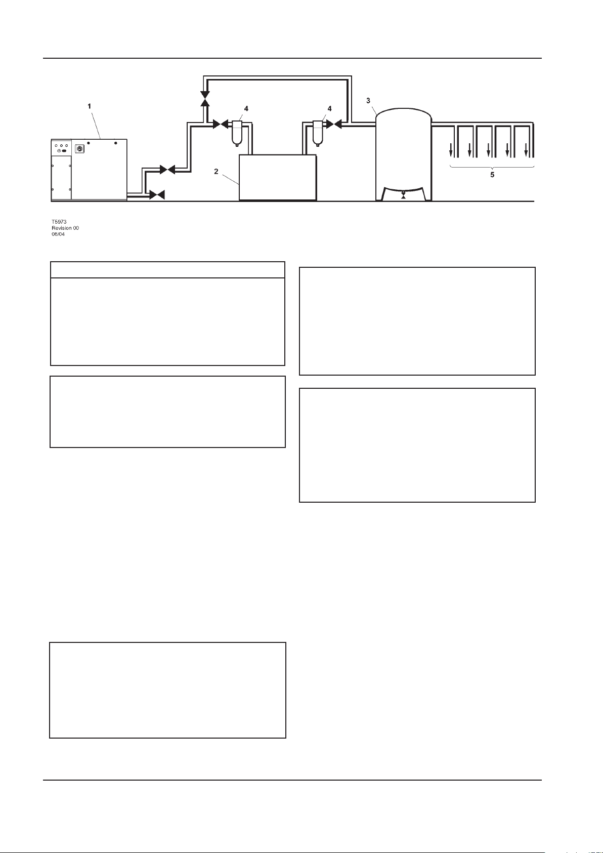
KEY
1.
Compressor
CAUTION
The use of plastic bowls on line lters and other
Air Receiver
2.
Air Dryer
3.
plastic air line components can be hazardous.
Their safety can be aected by either synthetic
coolants or the additives used in mineral oils.
Compressed air lters
4.
System demand points
5.
Ingersoll Rand recommends that only lters
with metal bowls should be used on any
pressurised system.
NOTE
Items [2] to [5] are optional or may be existing
items of plant. Refer to your Ingersoll Rand
distributor / representative for specic
recommendations.
LOCATION IN THE PLANT
The compressor can be installed on any level oor
capable of supporting it. A dry, well ventilated area
where the atmosphere is clean is recommended. A
minimum of 1m (3ft) should be left all around machine
for adequate service access and ventilation.
Adequate clearance needs to be allowed around and
above the machine to permit safe access for specied
maintenance tasks.
The standard compressor unit is not suitable
for operation in temperatures liable to cause
freezing as Condensate water is liable to be
produced in the after cooler and receiver where
tted.
Refer to your Ingersoll Rand distributor for
further information.
DISCHARGE PIPING
Discharge piping should be at least as large as the
discharge connection of the compressor. All piping
and ttings should be suitably rated for the discharge
pressure.
CAUTION
Ensure that the machine is positioned securely and on
a stable foundation. Any risk of movement should be
removed by suitable means, especially to avoid strain on
any rigid discharge piping.
It is essential when installing a new compressor [1],
to review the total air system. This is to ensure a safe
and eective total system. One item which should be
considered is liquid carryover. Installation of air
dryers [3] is always good practice since properly selected
CAUTION
Screw type compressors [1] should not be
installed in air systems with reciprocating
compressors without means of isolation such
and installed they can reduce any liquid carryover to
zero.
It is good practice to locate an isolation valve close to
the compressor and to install line lters [4].
as a common receiver tank. It is recommended
that both types of compressor be piped to a
common receiver using individual air lines.
It is a requirement for air dryers covered under AirCare
that correctly sized Ingersoll Rand pre and afterlters
are installed.
30 http://air.ingersollrand.com
Page 31
OPERATION AND MAINTENANCE MANUAL INSTALLATION / HANDLING
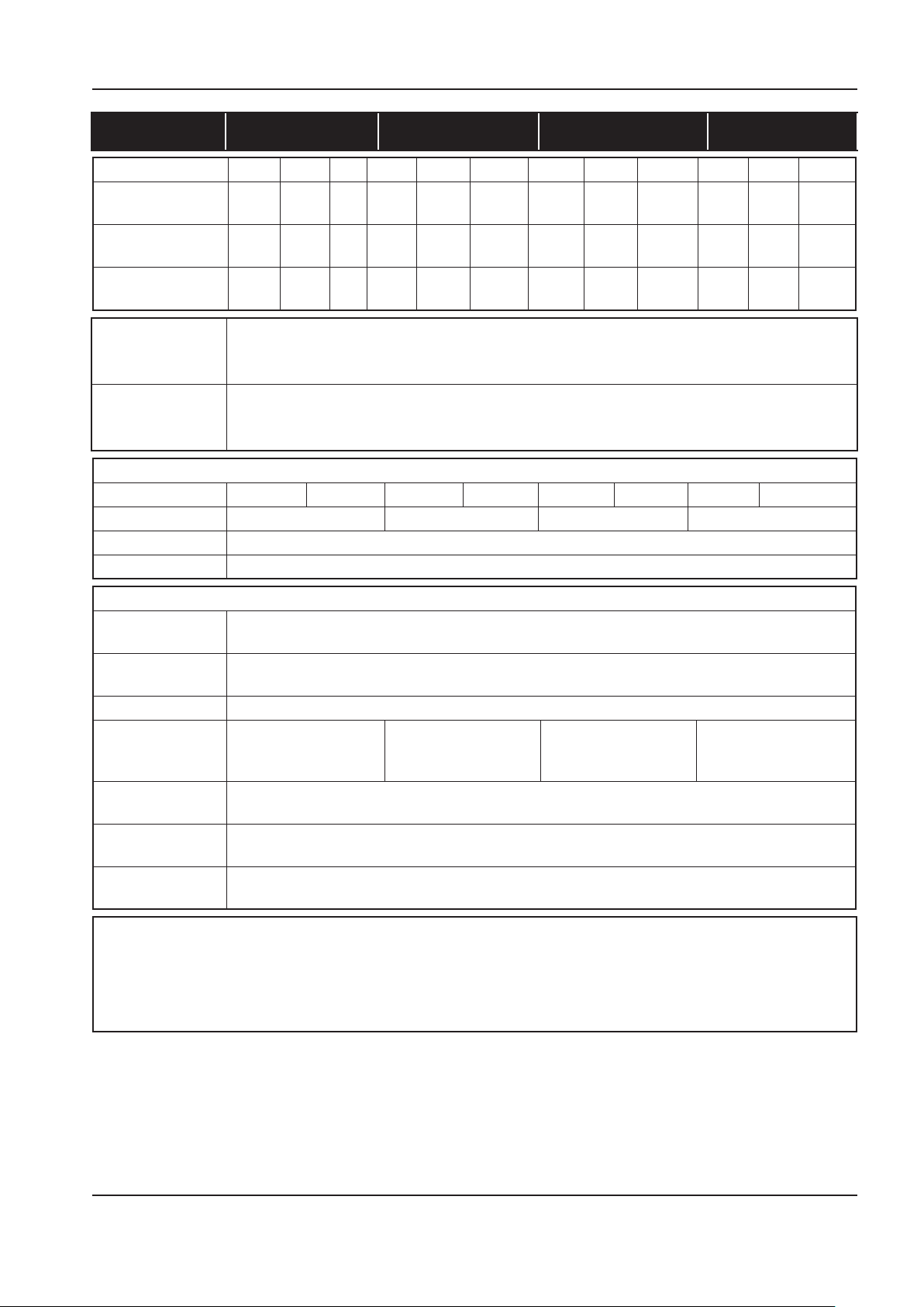
60Hz UP6 5 UP6 7 UP6 10 UP6 15c
COMPRESSOR 125 150 210 125 150 210 125 150 210 125 150 210
Operating pressure PSIG (bar)
Factory set reload
pressure PSIG (bar)
Flow rate CFM
(m3/MIN)
Airend discharge
temperature trip
point.
Ambient operating
temperature
(min.) →(max.)
MOTOR
Motor enclosure ODP TEFC ODP TEFC ODP TEFC ODP TEFC
Nominal power 5HP 7.5HP 10HP 15HP
Speed 3500 RPM
Insulation class F
GENERAL DATA
Residual coolant
content
Separator vessel
capacity
Coolant capacity 1.2 gallons (4.5 Litres)
Sound pressure
level to
CAGI-PNEUROP
Weight-base
mount unit
Weight-80 gallon
Receiver mounted
Weight-120 gallon
Receiver mounted
CAUTION
230/460 Dual voltage machines are tted with a decal to advise the correct voltage as connected from the factory.
There is a decal tted to the starter door describing the procedure to change the connections for the alternative
voltage.
Rewiring should only be eected by a competent Electrician.
125
(8.6)
110
(7.58)
18.5
(0.52)
150
(10.3)
130
(8.96)
16.0
(0.45)
-- 125
(8.6)
-- 110
(7.58)
-- 28.0
(0.79)
150
(10.3)
130
(8.96)
25.0
(0.71)
210
(14.5)
180
(12.41)
17.5
(0.50)
125
(8.6)
110
(7.58)
38.0
(1.08)
150
(10.3)
130
(8.96)
34
(0.96)
210
(14.5)
180
(12.41)
24.0
(0.68)
(7.58)
(1.55)
228°F (109°C)
36°F (+2°C) → 105°F (+40°C)
3ppm (3 mg/m3)
0.8 gallons (3 Litres)
65 dB(A) 65 dB(A) 68 dB(A) 69 dB(A)
295kg (650lb)
420kg (925lb)
436kg (960lb)
125
(8.6)
110
55.0
150
(10.3)
130
(8.96)
50.0
(1.42)
210
(14.5)
180
(12.41)
38.0
(1.08)
http://air.ingersollrand.com 31
Page 32
INSTALLATION / HANDLING OPERATION AND MAINTENANCE MANUAL
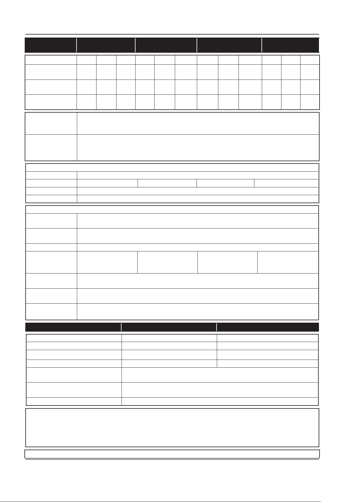
50Hz UP5 4 UP5 5 UP5 7 UP5 11c
COMPRESSOR 8 10 14.5 8 10 14.5 8 10 14.5 8 10 14.5
Operating pressure
PSIG (bar)
Factory set reload
pressure PSIG (bar)
Flow rate CFM
(m3/MIN)
Airend discharge
temperature trip
point.
Ambient operating
temperature
(min.) →(max.)
MOTOR
Motor enclosure TEFC
Nominal power 4KW 5.5KW 7.5KW 11KW
Speed 2900 RPM
Insulation class F
GENERAL DATA
Residual coolant
content
Separator vessel
capacity
Coolant capacity 1.2 gallons (4.5 Litres)
Sound pressure
level to
CAGI-PNEUROP
Weight-base
mount unit
Weight-272 LitresReceiver mounted
Weight-500 Litres
Receiver mounted
115
(8)
100
(7.58)
19.5
(0.55)
145
(10)
125
(8.96)
16.0
(0.45)
210
(14.5)
-- 100
-- 29.0
115
(8)
(7.93)
(0.82)
145
(10)
125
(9.66)
26.0
(0.74)
(13.10)
210
(14.5)
180
18.0
(0.51)
115
(8)
100
(7.93)
38.0
(1.08)
145
(10)
125
(9.66)
34
(0.96)
210
(14.5)
180
(13.10)
24.0
(0.68)
228°F (109°C)
36°F (+2°C) → 105°F (+40°C)
3ppm (3 mg/m3)
0.8 gallons (3 Litres)
65 dB(A) 65 dB(A) 68 dB(A) 69 dB(A)
295kg (650lb)
420kg (925lb)
454kg (1000lb)
115
(8)
100
(7.93)
56.5
(1.60)
145
(10)
125
(9.66)
50.0
(1.92)
210
(14.5)
180
(13.1)
38.0
(8.6)
DRYER ENGINEERING DATA 60Hz 50Hz
Electrical supply 115V - 1ph - 60Hz 230V - 1ph - 50Hz
L.R.A. current (Amps) 30.0 12.6
F.L.A. current (Amps) 5.0 2.7
Total installed power (kW) 0.46 0.47
Electrical protection class (std) NEMA 1
(IP 20)
Factory refrigerant charge (lb/g) 0.78 lb
354 g
Regeration type 134 A
CAUTION
230/460 Dual voltage machines are tted with a decal to advise the correct voltage as connected from the factory.
There is a decal tted to the starter door describing the procedure to change the connections for the alternative
voltage.
Rewiring should only be eected by a competent Electrician.
ELECTRICAL DATA-UP6 5
32 http://air.ingersollrand.com
Page 33
OPERATION AND MAINTENANCE MANUAL INSTALLATION / HANDLING
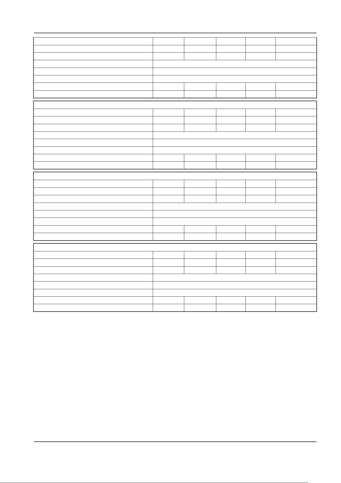
Standard voltage 230V/1PH 200V 230V/3PH 460V 575V
Full load current (maximum) 23.5A 15.5A 13.5A 6.8A 5.4A
Starting current DOL (Star Delta) - - - - Starting time DOL (Star Delta) 3–5 Sec (7–10 Sec)
Starts per hour (maximum) 6
Control voltage 120VAC
Recommended fuse rating See note 1 40A 25A 20A 10A 8A
Recommended wire size AWG See note 2 8 10 12 14 14
ELECTRICAL DATA-UP6 7.5
Standard voltage 230V/1PH 200V 230V/3PH 460V 575V
Full load current (maximum) 34.1A 22.7A 19.7A 9.9A 7.9A
Starting current DOL (Star Delta) - - - - Starting time DOL (Star Delta) 3–5 Sec (7–10 Sec)
Starts per hour (maximum) 6
Control voltage 120VAC
Recommended fuse rating See note 1 50A 35A 35A 15A 12A
Recommended wire size AWG See note 2 6 8 10 14 14
ELECTRICAL DATA-UP6 10
Standard voltage 230V/1PH 200V 230V/3PH 460V 575V
Full load current (maximum) - 29.8A 26.0A 13.0A 10.3A
Starting current DOL (Star Delta) - - - - Starting time DOL (Star Delta) 3–5 Sec (7–10 Sec)
Starts per hour (maximum) 6
Control voltage 120VAC
Recommended fuse rating See note 1 - 50A 45A 20A 15A
Recommended wire size AWG See note 2 - 8 8 12 14
ELECTRICAL DATA-UP6 15c
Standard voltage 230V/1PH 200V 230V/3PH 460V 575V
Full load current (maximum) - 43.2A 37.6A 18.8A 15.1A
Starting current DOL (Star Delta) - - - - Starting time DOL (Star Delta) 3–5 Sec (7–10 Sec)
Starts per hour (maximum) 6
Control voltage 120VAC
Recommended fuse rating See note 1 - 75A 65A 30A 25A
Recommended wire size AWG See note 2 - 4 6 10 10
1. If a circuit breaker is selected it should only be a magnetic trip type, set above the anticipated starting current
of the machine, but below the maximum prospective fault current for the circuit. The circuit breaker or fuseable
disconnect must be capable of breaking the prospective fault current at its terminals.
2. PVC/PVC Type Calculated using the following
conditions:
PVC insulated cable, armoured, copper
i)
conductors.
Cable clipped to a wall, in free air.
ii)
Ambient temperature of 40°C (104°F) and relative
iii)
20m (65ft) cable run.
iv)
v)
Volt drop limited to –10% during starting, –4%
during normal running.
vi)
Protected by the circuit breaker listed above.
humidity of 40%.
http://air.ingersollrand.com 33
Page 34

INSTALLATION / HANDLING OPERATION AND MAINTENANCE MANUAL
ELECTRICAL DATA-UP5 4
Standard voltage 380V 400V
Full load current (maximum) 8.9A 8.5A
Starting current DOL (Star Delta) 66 63
Starting time DOL (Star Delta) 3–5 Sec (7–10 Sec)
Starts per hour (maximum) 6
Control voltage 120VAC
Recommended fuse rating See note 1 16A 16A
Recommended wire size See note 2 4 mm2Cu 4 mm2 Cu
ELECTRICAL DATA-UP5 5.5
Standard voltage 380V 400V
Full load current (maximum) 11.8A 11.2A
Starting current DOL (Star Delta) 100 95
Starting time DOL (Star Delta) 3–5 Sec (7–10 Sec)
Starts per hour (maximum) 6
Control voltage 120VAC
Recommended fuse rating See note 1 16A 16A
Recommended wire size See note 2 4 mm2Cu 4 mm2 Cu
ELECTRICAL DATA-UP5 7.5
Standard voltage 380V 400V
Full load current (maximum) 16.9A 15.6A
Starting current DOL (Star Delta) 121 (94) 114 (52)
Starting time DOL (Star Delta) 3–5 Sec (7–10 Sec)
Starts per hour (maximum) 6
Control voltage 120VAC
Recommended fuse rating See note 1 20A 20A
Recommended wire size See note 2 4 mm2Cu 4 mm2 Cu
ELECTRICAL DATA-UP5 11c
Standard voltage 380V 400V
Full load current (maximum) 23.0A 21.9A
Starting current DOL (Star Delta) (79) (75)
Starting time DOL (Star Delta) 3–5 Sec (7–10 Sec)
Starts per hour (maximum) 6
Control voltage 120VAC
Recommended fuse rating See note 1 32A 32A
Recommended wire size See note 2 6 mm2Cu 6 mm2 Cu
1. If a circuit breaker is selected it should only be a
magnetic trip type, set above the anticipated starting
current of the machine, but below the maximum
prospective fault current for the circuit. The circuit
breaker or fuseable disconnect must be capable of
breaking the prospective fault current at its terminals.
2. PVC/PVC Type Calculated using the following
conditions:
PVC insulated cable, armoured, copper
i)
conductors.
Cable clipped to a wall, in free air.
ii)
Ambient temperature of 40°C (104°F) and relative
iii)
humidity of 40%.
20m (65ft) cable run.
iv)
Volt drop limited to –10% during starting, –4%
v)
during normal running.
Protected by the circuit breaker listed above.
vi)
34 http://air.ingersollrand.com
Page 35

OPERATION AND MAINTENANCE MANUAL INSTALLATION / HANDLING
If there are any deviations from the above, or special
regulations apply, the installation must be planned by a
competent, qualied engineer.
NOTE
All data applies to standard product only.
ELECTRICAL DATA
An independent electrical isolator or disconnect should
be installed adjacent to the compressor.
Feeder cables/wires should be sized by the customer/
electrical contractor to ensure that the circuit is
balanced and not overloaded by other electrical
equipment. The length of wiring from a suitable
electrical feed point is critical as voltage drops may
impair the performance of the compressor.
Feeder cables / wires connections to isolator or
disconnect should be tight and clean.
The applied voltage must be compatible with the motor
and compressor data plate ratings.
The control circuit transformer has dierent voltage
tappings. Ensure that these are set for the specic
applied voltage prior to starting.
CAUTION
Never test the insulation resistance of any part
of the machines electrical circuits, including the
motor without completely disconnecting the
electronic controller (where tted).
CAUTION
Ensure that the motor rotates in the correct
direction as indicated by direction arrows.
http://air.ingersollrand.com 35
Page 36

OPERATING INSTRUCTIONS OPERATION AND MAINTENANCE MANUAL
OPERATING INSTRUCTIONS
GENERAL OPERATION
The compressor is an electric motor driven, single
stage screw compressor, complete with accessories
piped, wired and base plate mounted. It is a totally self
contained air compressor package.
The standard compressor is designed to operate in
an ambient range of 35.6°F - 104°F (2°C to 40°C). The
maximum temperature is applicable up to a maximum
elevation of 3280ft (1000m) above sea level. Above this
altitude signicant reduction in maximum allowable
ambient temperature is required.
Compression in the screw type air compressor is created
by the meshing of two (male & female) helical rotors.
The air/coolant mixture discharges from the compressor
into the separation system. This system removes all
but a few PPM of the coolant from the discharge air.
The coolant is returned to the cooling system and
the air passes through the aftercooler and out of the
compressor.
Cooling air is moved through the coolers by the cooling
fan and discharged from the machine.
CAUTION
Cooling air is drawn in at the rear of the machine
package passing through the lter and cooler
before being discharged from the top of
the machine. Care should be taken to avoid
blocking the airow, or causing any restriction
in excess of the maximum backpressure allowed
for ducting.
WARNING
When the unit stops running as the result of low
air demand, it may restart and return to load at
any time.
Safety of operation is provided as the compressor
will shut down if excessive temperatures or electrical
overload conditions should occur.
CAUTION
This unit is not designed or intended to operate
when contaminated with silicone. Lubricants,
greases or other items containing silicone
should not be used on this unit.
CAUTION
LOW DEMAND APPLICATIONS
During periods of low demand, the compressor
may not reach its normal operating
temperature. Sustained operation at low
demand can result in the build up of condensate
in the coolant. If this situation occurs, the
lubricating characteristics of the coolant can
be impaired which may lead to damage of the
compressor.
THE COMPRESSOR SHOULD BE ALLOWED
AMPLE LOADED RUNNING TIME OF AT LEAST 10
MINUTES PER HOUR DURING NORMAL DAILY
USE.
Do not direct the airow at face or eyes.
By cooling the discharge air, much of the water vapour
naturally contained in the air is condensed and may be
drained from the downstream piping and equipment.
The coolant system consists of a sump, cooler,
thermostatic valve and a lter. When the unit is
operating, the coolant is pressurized and forced to the
compressor bearings.
The compressor load control system is automatic on-
o line. This allows the compressor to maintain a set
discharge line pressure by varying output capacity to
match the system demand. The unit is provided with
an automatic stop and restart system for use in plants
where the air demand varies suciently to allow a
compressor to shut down and save power. Signicant
system volume will assist this and is recommended.
When the compressor is equipped with the optional
dryer, the dryer will cycle on and o with the
compressor.
36 http://air.ingersollrand.com
Page 37
OPERATION AND MAINTENANCE MANUAL OPERATING INSTRUCTIONS
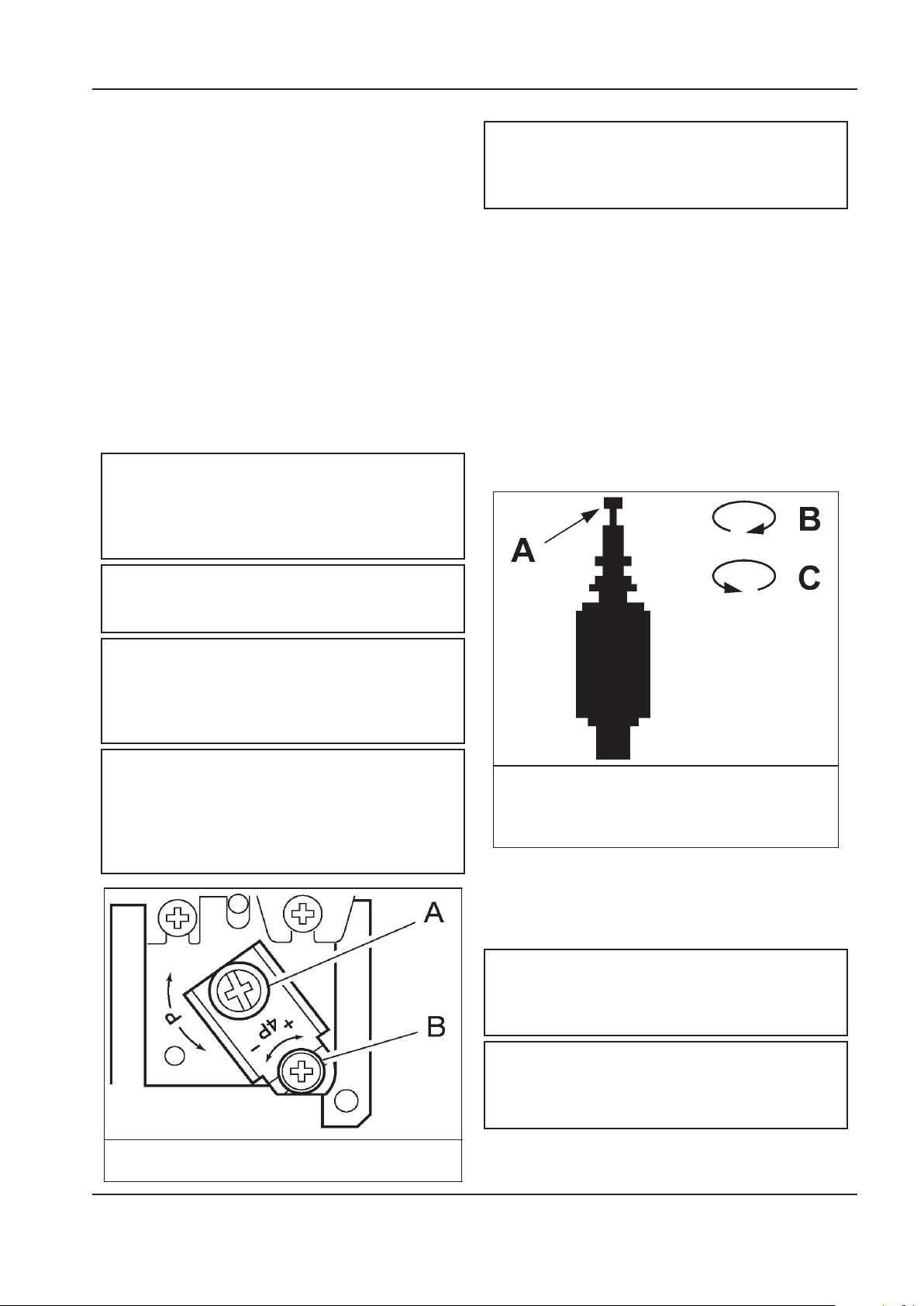
A. Upper Pressure Setting
B. Pressure Differential
Auxiliary Valve.
A. Knob
B. Clockwise
C. Counterclockwise
COMPRESSOR CONTROLS
Direct online starting:
The compressor is equipped for Automatic Start & Stop
Control. When the receiver tank pressure reaches the
factory pre–set maximum pressure, the pressure switch
stops the unit. When the receiver tank pressure drops
below the factory pre–set minimum. The pressure
switch resets and restarts the unit.
The pressure switch cover can be removed by
unscrewing the two screws holding the cover.
Pressure switch adjustment:
The compressor package will cut–in and cut–out at
factory preset pressure settings. Adjust the pressure
switch only if absolutely necessary.
Adjustments are to be carried out only when the switch
is mounted, under pressure and voltage–free.
WARNING
High voltage is present at the pressure switch
contacts when the power supply is connected.
Disconnect, lock and tag main power supply
before making adjustments.
WARNING
AUTOMATIC START & STOP CONTROL
NOTE
Automatic Start & Stop Control is intended for
use when the motor will start no more than 6
times per hour.
When the receiver tank pressure reaches the factory
pre–set maximum pressure, the pressure switch stops
the unit. When the receiver tank pressure drops below
the factory pre–set minimum, the pressure switch resets
and restarts the unit.
DUAL CONTROL
Select either automatic start and stop control or
constant speed control by adjusting the knob on the
auxiliary valve. For automatic start and stop control, turn
the knob on the auxiliary valve fully clockwise to disable
the auxiliary valve. The pressure switch will then start
and stop the unit.
Do not adjust the pressure switch to exceed the
maximum discharge pressure of the unit.
NOTE
When replacing the pressure switch cover,
ensure the selector knob on the cover and
the lever on the switch are both in the ”OFF”
position.
NOTE
When the compressor is equipped with the
optional dryer and lters, the pressure switch
dierential should be increased 10psi to account
for the added pressure drop of the lters and
dryer.
Select constant speed control if the unit restarts in less
than 10 minute intervals or runs more than 40 minutes
per hour. Turn the knob fully counterclockwise to run
the unit continually.
NOTE
The auxilIary valve is factory pre–set at 5 psig
(0,3 bar) lower than the factory pressure switch
setting.
CAUTION
http://air.ingersollrand.com 37
Running unloaded with no air demand, will
cause the unit to be shuto by the pressure
switch.
Page 38
OPERATING INSTRUCTIONS OPERATION AND MAINTENANCE MANUAL
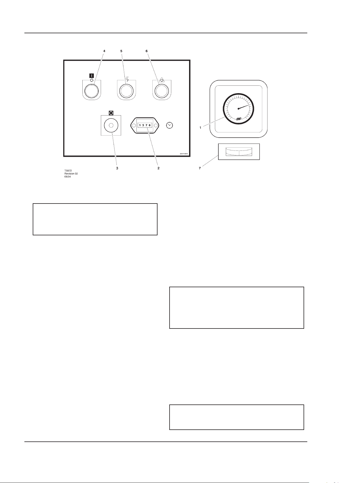
1. PRESSURE GAUGE
Indicates the system pressure.
WARNING
DO NOT operate the compressor at discharge
pressures exceeding the maximum operating
pressure.
2. HOURMETER
Records the total running time of the compressor.
3. STOP BUTTON / EMERGENCY STOP
When depressed will stop the compressor
immediately. The ’Power on’ indicator will remain
illuminated. The STOP button must be released
before the compressor can be restarted.
4. ON PUSH BUTTON SWITCH
When depressed will cause the unit to start and
run in a loaded condition if there is a demand for
air. If there is no demand, the machine will stop
automatically.
5. POWER ON INDICATOR LIGHT (Green)
Indicates the presence of control voltage.
6. STOPPED/AUTO RESTART INDICATOR LIGHT
(Amber)
Will illuminate when the machine has shut-down
due to low air demand. The machine will restart
and load automatically as soon as the demand for
air returns.
7. DEW POINT INDICATOR (Dryer Option)
Green indicates good dew point. Red indicates
ew point above 50°F (10°C) Blue indicates
freezing.
PRIOR TO STARTING
1. Make visual check of the machine, ensure that
all guards secure and that nothing is obstructing
the proper ventilation of, or free access to the
machine.
2. Check coolant level. Add if necessary.
3. Make sure air discharge valve is open.
4. Turn on electrical isolator or disconnect. The
Power on (5) indicator will light, indicating that
line and control voltages are available.
5. Check direction of rotation at initial start or
following interruption in power supply.
WARNING
Make sure that all protective covers are in place.
Cooling air ow exhaust may contain ying
debris. Safety protection should be worn at all
times to avoid injury.
STARTING
1. Press the START button. The compressor will start
and then load automatically.
NORMAL/EMERGENCY STOPPING
1. Press STOP button (3) and the compressor will
stop immediately.
2. Turn o electrical isolator or disconnect.
CAUTION
After shutdown never allow unit to stand idle with
pressure in receiver/separator system.
38 http://air.ingersollrand.com
Page 39
OPERATION AND MAINTENANCE MANUAL MAINTENANCE
MAINTENANCE
MAINTENANCE SCHEDULE
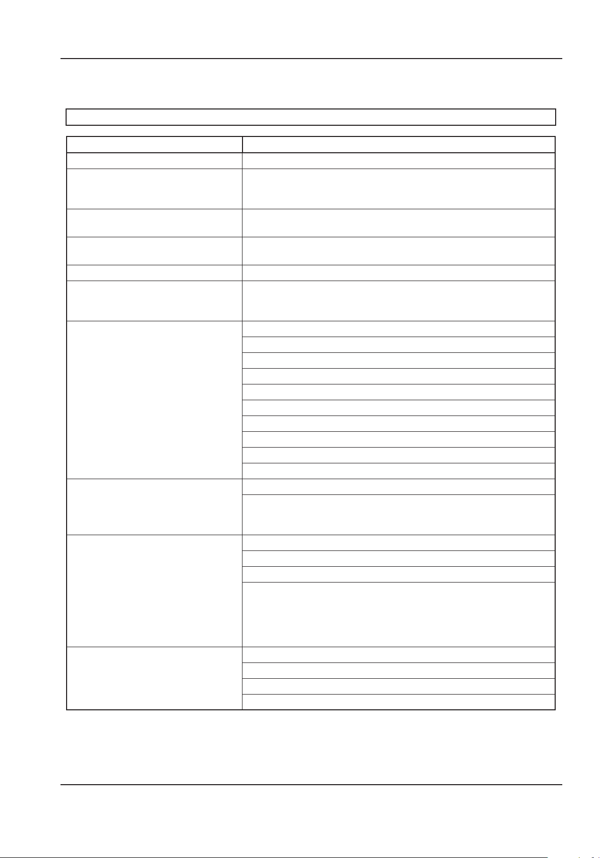
UP Series Maintenance Schedule
PERIOD MAINTENANCE
Each 24 hours operation Check the coolant level and replenish if necessary.
Visual check of machine for any leaks,
dust build up or unusual noise or
vibration
When compressor is receiver mounted Drain air receiver of condensate, or check that automatic drain is
Visual check condition of package prelter
First 150 hours Change the coolant lter.
Each month or 100 hours Remove and clean package pre-lter, replace if needed
Each year or 2000 hours Check the operation of the high temperature protection switch (109˚C).
1 year external and 6 years internal
pressure vessel inspection.
Frequency may be otherwise dened
by local or national legislation.
Every two years or 8000 hours Change drive belts.
Every 4 years or 16000 hours Replace all hoses.
Report immediately, contact Ingersoll Rand authorized distributor for
assistance if in doubt.
operating.
Blow clean if needed.
Check the cooler(s) for build up of foreign matter. Clean if necessary by
blowing out with air or by pressure washing.
Replace elements in IRGP and IRHE lters.
Change the coolant lter.
Check scavenge screen for blockage, clean if required.
Change the separator element.
Change the Air Filter element.
Take coolant sample for uid analysis.
Change the package pre–lter.
Check Drive Belts.
Motors without grease ttings - Replace sealed bearings
Separator vessel and air receiver when tted.
Fully inspect all external surfaces, and ttings. Report any excessive
corrosion, mechanical or impact damage, leakage or other
deterioration.
Replace the Ultra at whichever interval occurs rst.
Check and replace all items included within 2000 hour service.
Fit the following reconditioning parts as appropriate:
Solenoid valves
Inlet valve kit
Minimum Pressure valve kit
Thermostatic Valve Kit
Check motors with grease ttings and grease per motor data tag
Fit replacement electrical contactor tips.
Motors without grease ttings - Replace sealed bearings
http://air.ingersollrand.com 39
Page 40

40 http://air.ingersollrand.com
MAINTENANCE OPERATION AND MAINTENANCE MANUAL
ROUTINE MAINTENANCE
This section refers to the various components which
require periodic maintenance and replacement.
It should be noted that the intervals between service
requirement may be signicantly reduced as a
consequence of poor operating environment. This
would include eects of atmospheric contamination
and extremes of temperature.
The SERVICE/MAINTENANCE CHART indicates the various
components’ descriptions and the intervals when
maintenance has to take place. Oil capacities, etc., can
be found in the GENERAL INFORMATION section of this
manual.
Compressed air can be dangerous if incorrectly
handled. Before doing any work on the unit, ensure
that all pressure is vented from the system and that the
machine cannot be started accidentally.
CAUTION
Before beginning any work on the compressor,
open, lock and tag the main electrical
disconnect and close the isolation valve on
the compressor discharge. Vent pressure from
the unit by slowly unscrewing the coolant ll
cap one turn. Unscrewing the ll cap opens a
vent hole, drilled in the cap, allowing pressure
to release to atmosphere. Do not remove the
ll cap until all pressure has vented from the
unit. Also vent piping by slightly opening the
drain valve. When opening the drain valve or
the coolant ll cap, stand clear of the valve
discharge and wear appropriate eye protection.
Ensure that maintenance personnel are properly trained,
competent and have read the Maintenance Manuals.
Prior to attempting any maintenance work, ensure
that:-
all air pressure is fully discharged and isolated
•
from the system. If the automatic blowdown
valve is used for this purpose, then allow enough
time for it to complete the operation.
the machine cannot be started accidentally or
•
otherwise.
all residual electrical power sources (mains and
•
battery) are isolated.
Prior to opening or removing panels or covers to
work inside a machine, ensure that:-
anyone entering the machine is aware of the
•
reduced level of protection and the additional
hazards, including hot surfaces and intermittently
moving parts.
the machine cannot be started accidentally or
•
otherwise.
Prior to attempting any maintenance work on a
running machine, ensure that:-
DANGER
Only properly trained and competent persons
should undertake any maintenance tasks with
the compressor running or with electrical power
connected.
the work carried out is limited to only those tasks
•
which require the machine to run.
the work carried out with safety protection
•
devices disabled or removed is limited to only
those tasks which require the machine to be
running with safety protection devices disabled
or removed.
all hazards present are known (e.g. pressurised
•
components, electrically live components,
removed panels, covers and guards, extreme
temperatures, inow and outow of air,
intermittently moving parts, safety valve
discharge etc.).
appropriate personal protective equipment is
•
worn.
loose clothing, jewellery, long hair etc. is made
•
safe.
warning signs indicating that Maintenance Work
•
is in Progress are posted in a position that can be
clearly seen.
Upon completion of maintenance tasks and prior to
returning the machine into service, ensure that:-
the machine is suitably tested.
•
all guards and safety protection devices are
•
retted and correctly working.
all panels are replaced, canopy and doors closed.
•
hazardous materials are eectively contained and
•
disposed of in a manner compliant with local or
National environmental protection codes.
Page 41
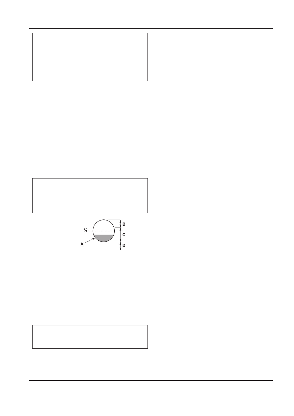
OPERATION AND MAINTENANCE MANUAL MAINTENANCE
A. Correct at operating temperature
B. Too much
C. OK
D. Too little
WARNING
Do not under any circumstances open any
drain valve or remove components from the
compressor without rst ensuring that the
compressor is FULLY SHUT- DOWN, power
isolated and all air pressure relieved from the
system.
TOP UP COOLANT PROCEDURE
Slowly remove ll cap.
1.
Pour coolant into spout untill spout almost
2.
overows.
Replace and tighten oil ll cap.
3.
Start unit for about 10 seconds (until coolant
4.
drains out the bottom of the sight glass).
Slowly remove ll cap.
5.
Re–ll into spout until spout almost overows.
6.
Replace and tighten oil ll cap.
7.
Run unit.
8.
NOTE
Coolant level is correct when a unit is showing
coolant in bottom half of sight glass when up
to operating temperature (ten minutes running
loaded).
COOLANT CHANGE PROCEDURE
It is better to drain the coolant immediately after
the compressor has been operating as the liquid will
drain more easily and any contaminant will still be in
suspension.
Stop the machine, electrically isolate and vent all
1.
trapped pressure.
Place a suitable container close to the drain valve.
2.
Slowly remove ll cap.
3.
Remove plug from drain valve.
4.
Open the drain valve and drain coolant into
5.
container.
Close the drain valve.
6.
Replace plug in drain valve.
7.
Rell the machine following the ”top up coolant”
8.
procedure above. After initial ll, to purge any
airlocks, the machine should be run for a few
minutes cycling between load and no load,
before checking that the level is correct.
Replace and tighten oil ll cap.
9.
COOLANT FILTER CHANGE PROCEDURE
Stop the machine, electrically isolate and vent all
1.
trapped pressure.
Loosen lter with the correct tool.
2.
Repeat this procedure to get coolant to proper level
when up to operating temperature.
When the unit is shut down, coolant will usually ll
up sight glass. Do not adjust level based on level at
shutdown. Proper level is always set for a running unit at
operating temperature.
CAUTION
Ensure that SSR ULTRA is used. Failure to do so
will void manufacturers warranty.
Remove the lter from the housing.
3.
Place the old lter in a sealed bag and dispose of
4.
in a safe way.
Clean the mating face of the housing taking care
5.
to avoid any particles entering the machine.
Remove the new Ingersoll Rand replacement
6.
lter from its protective package.
Apply a small amount of lubricant to the lter
7.
seal.
Screw the new lter down until the seal makes
8.
contact with the housing, then hand tighten a
further half turn.
Start the compressor and check for leaks.
9.
AIR FILTER ELEMENT CHANGE PROCEDURE
Stop the machine, electrically isolate and vent all
1.
trapped pressure.
Unscrew the retaining cap and withdraw the old
2.
element.
Fit the new element.
3.
http://air.ingersollrand.com 41
Replace the retaining cap.
4.
Page 42
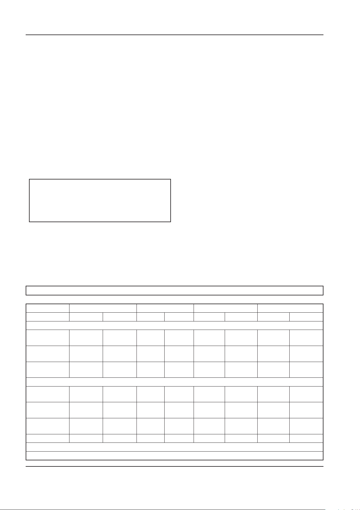
42 http://air.ingersollrand.com
MAINTENANCE OPERATION AND MAINTENANCE MANUAL
Clean the cooler.
SEPARATOR ELEMENT CHANGE PROCEDURE
Stop the machine, electrically isolate and vent all
1.
trapped pressure.
Loosen separator element with the correct tool.
2.
Remove the element from the housing; place it in
3.
a sealed bag and dispose of it safely.
Clean the mating face of the housing.
4.
Remove the new Ingersoll Rand replacement
5.
element from its protective package.
Apply a small amount of lubricant to the element
6.
seal.
Screw the new element down until the seal
7.
makes contact with the housing, then hand
tighten a further half turn.
Start the compressor and check for leaks.
8.
CAUTION
This unit is not designed or intended to operate
when contaminated with silicone. Lubricants,
greases or other items containing silicone
should not be used on this unit.
COOLER CLEANING PROCEDURE
Stop the machine, electrically isolate and vent all
1.
trapped pressure.
3.
Rebuild in reverse order.
4.
BELT CHECKING AND ADJUSTMENT PROCEDURE
Check belt tension occasionally, especially if looseness
is suspected. A quick check to determine if adjustment
is proper may be made by observing the slack side of
the belt for a slight bow when the unit is in operation.
If a slight bow is evident, the belt is usually adjusted
satisfactorily.
A belt tension measurement device can be used to
determine the tension of the belt.
Belt tensioning can be achieved by loosening the airend
anchor screws, a belt tensioning bolt is provided to aid
in moving the airend.
Follow the procedures outlined below to correctly set
and measure belt tension.
1. Lay a straight edge across the top outer surface of
the belt drive from pulley to sheave.
2. At the center of the span, perpendicular to the
belt, apply pressure to the outer surface of the
belt with a tension gauge. Force the belt to the
deection indicated in the table below, and
compare the reading on the tension gauge to the
gures shown.
Remove the top cover to obtain access to the
2.
cooler.
BELT TENSION
New Used New Used New Used New Used
60hz
125 psig 75 Lb
(34 Kg)
150 psig 75 Lb
(34 Kg)
210 psig 75 Lb
(34 Kg)
50hz
8 bar 85 Lb
(39 Kg)
10 bar 90 Lb
(41 Kg)
14.5 bar 90 Lb
(41 Kg)
5hp/4kw * 7.5hp/5.5kw * 10hp/7.5kw * 15hp/11kw **
62 Lb
(28 Kg)
62 Lb
(28 Kg)
62 Lb
(28 Kg)
70 Lb
(32 Kg)
75 Lb
(34 Kg)
75 Lb
(34 Kg)
110 Lb
(50 Kg)
90 Lb
(41 Kg)
90 Lb
(41 Kg)
85 Lb
(39 Kg)
85 Lb
(39 Kg)
100 Lb
(45 Kg)
90 Lb
(41 Kg)
75 Lb
(34 Kg)
75 Lb
(34 Kg)
70 Lb
(32 Kg)
70 Lb
(32 Kg)
80 Lb
(36 Kg)
110 Lb
(50 Kg)
110 Lb
(50 Kg)
110 Lb
(50 Kg)
110 Lb
(50 Kg)
120 Lb
(54 Kg)
120 Lb
(54 Kg)
90 Lb
(41 Kg)
90 Lb
(41 Kg)
90 Lb
(41 Kg)
90 Lb
(41 Kg)
100 Lb
(45 Kg)
100 Lb
(45 Kg)
140 Lb
(64 Kg)
140 Lb
(64 Kg)
150 Lb
(68 Kg)
140 Lb
(64 Kg)
140 Lb
(64 Kg)
150 Lb
(68 Kg)
120 Lb
(54 Kg)
120 Lb
(54 Kg)
125 Lb
(57 Kg)
120 Lb
(54 Kg)
120 Lb
(54 Kg)
125 Lb
(57 Kg)
* ”Krikit I” gauge or equal
** ”Krikit II” gauge or equal
Page 43
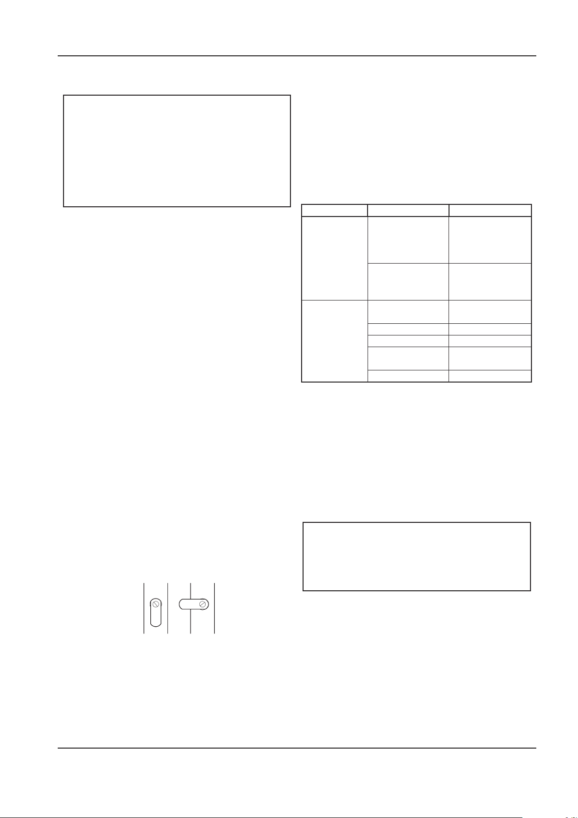
OPERATION AND MAINTENANCE MANUAL MAINTENANCE
Strainer Ball Valve.
OPEN CLOSED
Ensure the pulley and sheave are properly aligned and
the motor anchor screws are adequately retightened
prior to restarting the compressor.
cycles from 30 seconds to 45 minutes. The “time on”
setting determines the actual time the compressor
drains condensate.
CAUTION
Improper pulley/sheave alignment and belt
tension can result in motor overload, excessive
vibration, and premature belt and/or bearing
failure.
To prevent these problems from occurring,
ensure the pulley and sheave are aligned and
belt tension is satisfactory after installing new
belts or tensioning existing belts.
ELECTRIC DRAIN VALVE (OPTIONAL)
PRODUCT DESCRIPTION
The Electric Drain Valve removes condensed water and
oil from the air receiver tank. Additional drains may
be installed throughout your compressed air system,
including aftercoolers, lters, drip legs and dryers.
The Electric Drain Valve operates on a timer which can
be set to automatically drain the air receiver tank at
operator-determined intervals.
Key features include:
100% continuous duty
•
NEMA 4 enclosure
•
The timer’s cycle rate and drain opening time should
be adjusted to open just long enough to discharge the
condensate. The timer is properly set when it opens
and discharges condensate and then vents air for
approximately one second before closing. Adjustments
may be made depending on many factors, including
humidity and duty cycle.
TROUBLESHOOTING
TROUBLE CAUSE ACTION
Valve will not
close.
Timer will not
activate
MAINTENANCE
Debris in solenoid
valve prevents
diaphragm from
seating.
Short in electrical
component.
No electrical supply.
Timer malfunction Replace timer.
Clogged port. Clean valve.
Solenoid valve
malfunction.
Clogged strainer. Clean strainer.
Remove solenoid
valve, disassemble,
clean and reassemble.
Check and replace
power cord or
timer as needed.
Apply power.
Replace solenoid
valve.
Adjustable time on (0.5 - 10 seconds)
•
Adjustable time o (0.5 - 45 minutes)
•
Stainless steel operator
•
LED to indicate electrical power is on
•
LED to indicate valve is open
•
Manual override
•
OPERATION
Open the strainer ball valve.
1.
2. Set the “time o” and “time on” knobs. See TIMER
SETTINGS (below) for an explanation of the
settings.
3. During compressor operation, check for air leaks.
TIMER SETTINGS
The “time o” setting determines the interval between
Periodically clean the screen inside the valve to keep
the drain functioning at maximum capacity. To do this,
perform the following steps:
Close the strainer ball valve completely to isolate
1.
it from the air receiver tank.
Press the TEST button on the timer to vent the
2.
pressure remaining in the valve. Repeat until all
pressure is removed.
CAUTION
High pressure air can cause injury from
ying debris. Ensure the strainer ball valve is
completely closed and pressure is released from
the valve prior to cleaning.
3. Remove the plug from the strainer with a
suitable wrench. If you hear air escaping from
the cleaning port, STOP IMMEDIATELY and repeat
steps 1 and 2.
4. Remove the stainless steel lter screen and clean
it. Remove any debris that may be in the strainer
body before replacing the lter screen.
5. Replace plug and tighten with wrench.
6. When putting the Electric Drain Valve back into
service, press the TEST button to conrm proper
function.
http://air.ingersollrand.com 43
Page 44
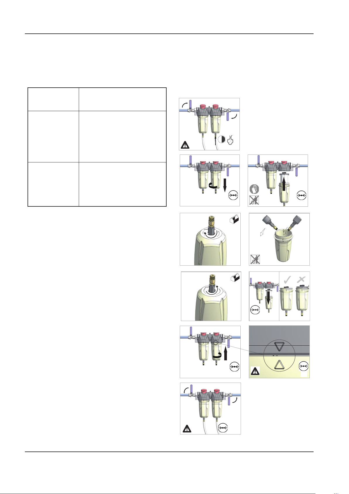
44 http://air.ingersollrand.com
MAINTENANCE OPERATION AND MAINTENANCE MANUAL
1
2
2
3
> 30s
4
5
0 bar
0 psi
1
2
0 bar
0 psi
7 8
0 bar
0 psi
9 10
2
1
0 bar
0 psi
0 bar
0 psi
1
2
12
5 6
1
Before accessing live electrical parts, disconnect the
AIR FILTER MAINTENANCE
power supply to the dryer using disconnect switch or
disconnect the cable connections.
In order to ensure optimum compressed air quality the
lter element should be replaced as follows. (Used lter
Preventive maintenance
For optimum performance from your dryer, follow the
periodic maintenance schedule described below.
WEEKLY CONDENSATE DRAINS
elements must be disposed of in accordance with local
regulations.)
Use only genuine Ingersoll Rand replacement
elements.
Verify that the condensate drains
are operating correctly.
EVERY 4 MONTHS CONDENSER
Remove any dust from the condenser ns.
COMPRESSOR
Make sure compressor power
consumption complies with data
YEARLY CONDENSATE DRAINS
plate specications.
Completely disassemble the
drains and clean all their components.
AIR FILTER
Replace air lter element.
MOISTURE SEPARATOR MAINTENANCE
The moisture separator will operate indenitely under
normal working conditions, however at some time
it may be necessary to replace the seals should the
housing leak.
Isolate the housing from the air supply.
1.
2.
3.
Fully depressurize in drain bowl as appropriate.
Unscrew bowl and remove. If pressure has not
been completely released from the housing,
air will escape from the warning hole giving
an audible alarm. Screw back bowl and repeat
instruction 2 before attempting again. Should
resistance to unscrewing be experienced,
provision is made for a ’C’ spanner to t onto the
ribs of the bowl.
Check condition of bowl seal and replace if
4.
necessary. Clean screw threads.
Ret bowl with ’O’ ring seal.
5.
Repressurize and check for leaks. If leaks occur
6.
they will most probably be from the bowl ’O’
ring. Depressurize housing and remove ’O’ ring as
stated above and inspect and clean. Ensure that
mating surfaces are clean and then ret ’O’ ring
and repressurize.
Page 45
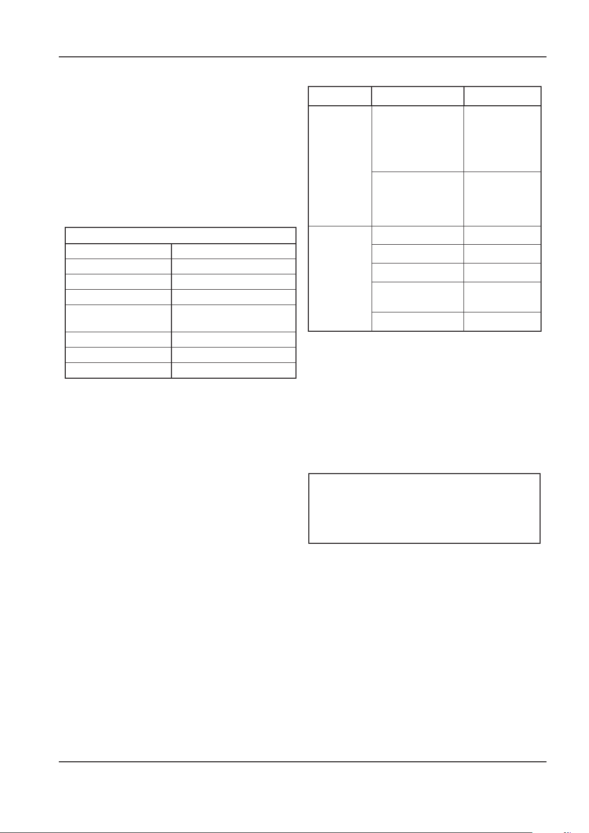
OPERATION AND MAINTENANCE MANUAL MAINTENANCE
DISASSEMBLING THE UNIT
The unit has been designed and constructed to
guarantee continuous operation.
The long service life of some components such as the
fan and compressor depends on good maintenance.
The unit must only be disassembled by a refrigerant
specialist.
Refrigerant liquid and lubricating oil inside the
refrigeration circuit must be recovered in compliance
with current norms in the country where the machine is
installed.
RECYCLING DISASSEMBLY
Frame and panels Steel / epoxy resin polyester
Heat exchanger (cooler) Stainless steel
Pipes Copper
Insulation Gum synthetic
Compressor Steel / copper / aluminium
/ oil
Condenser Aluminium
Refrigerant R134a
Valve Steel
REFRIGERANT LEAKS IN THE REFRIGERATION
CIRCUIT
The unit is despatched in perfect working order, already
charged.
Refrigerant leaks may be identied by tripping of the
refrigeration overload protector.
IF A LEAK IS DETECTED IN THE REFRIGERANT CIRCUIT,
SEEK TECHNICAL ASSISTANCE.
REFRIGERANT CHARGING
THIS OPERATION MUST ONLY BE PERFORMED BY A
REFRIGERANT SPECIALIST.
WHEN REPAIRING THE REFRIGERANT CIRCUIT,
COLLECT ALL THE REFRIGERANT IN A CONTAINER
AND DISPOSE OF IT IN THE APPROPRIATE MANNER.
CHARACTERISTICS OF REFRIGERANT R134A
In normal temperature and pressure conditions the
above refrigerant is a colorless, class A1/A1 gas with TVL
value of 1000 ppm (ASHRAE classication).
If a refrigerant leak occurs, thoroughly air the room
before commencing work.
TROUBLESHOOTING
TROUBLE CAUSE ACTION
Solenoid
condensate
valve will
not close.
Drain timer
will not
operate.
Debris in solenoid
valve prevents
diaphragm from
seating.
Short in electrical
component.
No electrical supply. Apply power.
Timer malfunction Replace timer.
Clogged port. Clean valve.
Solenoid valve
malfunction.
Clogged strainer. Clean strainer.
Remove
solenoid valve,
disassemble,
clean and
reassemble.
Check and
replace power
cord or timer as
needed.
Replace
solenoid valve.
MAINTENANCE
Periodically clean the screen inside the valve to keep
the drain functioning at maximum capacity. To do this,
perform the following steps:
Close the strainer ball valve completely to isolate
1.
it from the air receiver tank.
Press the TEST button on the timer to vent the
2.
pressure remaining in the valve. Repeat until all
pressure is removed.
CAUTION
High pressure air can cause injury from
ying debris. Ensure the strainer ball valve is
completely closed and pressure is released from
the valve prior to cleaning.
3. Remove the plug from the strainer with a
suitable wrench. If you hear air escaping from
the cleaning port, STOP IMMEDIATELY and repeat
steps 1 and 2.
4. Remove the stainless steel lter screen and clean
it. Remove any debris that may be in the strainer
body before replacing the lter screen.
5. Replace plug and tighten with wrench.
6. When putting the Electric Drain Valve back into
service, press the TEST button to conrm proper
function.
http://air.ingersollrand.com 45
Page 46

TROUBLE SHOOTING OPERATION AND MAINTENANCE MANUAL
TROUBLE SHOOTING
PROBLEM CAUSE REMEDY
Compressor fails to
start
Machine shuts down
periodically
High current draw Compressor operating above rated
Low current draw Air lter contaminated. Change air lter.
High discharge
pressure
Low system air
pressure
High dewpoint Refrigeration compressor not supplied
Ice formation in dryer Low evaporator pressure. Check hot gas valve setting.
Mains power or Control voltage not
available.
Defective Star / Delta timer. § Change Star / Delta timer.
High airend temperature. Top up coolant.
Motor overload. § Set overload to correct value and switch to
Line voltage variation. § Ensure voltage does not drop below 10% on
pressure.
Separator cartridge contaminated. Change air lter, and separator element.
Low voltage. § Ensure voltage does not drop below 10% on
Unbalanced voltage. Correct incoming supply voltage.
Damaged airend. † Change Airend.
Compressor operating unloaded. Set pressure to correct rating for machine.
High voltage. Reduce site voltage to correct operating
Defective inlet valve. † Fit inlet valve service kit.
Defective or incorrect pressure switch
setting.
Blowdown valve defective. † Fit blowdown solenoid service kit.
Inlet valve malfunction. † Fit inlet valve service kit.
Separator cartridge contaminated. Fit new Separator element.
Incorrect pressure transducer setting Set pressure to correct rating for machine.
Minimum pressure valve malfunction. † Fit Minimum pressure valve service kit.
Blowdown valve defective. † Fit blowdown solenoid service kit.
Drive belt slipping. Fit new belt.
Air system leaks. † Fix leaks.
Inlet valve malfunction. † Fit inlet valve service kit.
System demand exceeds compressor
delivery.
Compressed air lters contaminated. Replace air lter elements.
power.
Condensate system malfunction. Check operation of drain valve.
Condenser dirty. Clean condenser and replace panel lter
§
Check incoming power supply.
§
Check the control circuit fuse.
§
Check the transformer secondary windings
for the control voltage.
manual reset.
start up and 6% running.
Set pressure to correct rating for machine.
start up and 6% running.
voltage.
Replace or set pressure to correct rating for
machine.
Reduce demand or install additional
compressor.
Check incoming power supply.
Check the dryer protection fuse.
Check auxiliary contact on main motor
contactor.
Check operation of condensate check valves.
element.
46 http://air.ingersollrand.com
Page 47
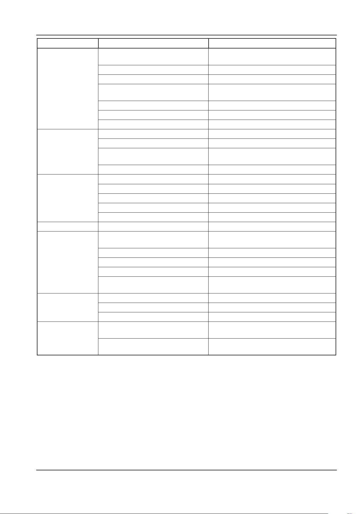
OPERATION AND MAINTENANCE MANUAL TROUBLE SHOOTING
PROBLEM CAUSE REMEDY
Compressor trips
due to over temperature
Excessive coolant
consumption
Excessive noise level Air system leaks. † Fix leaks.
Shaft seal leaking Defective shaft seal. † Fit Airend shaft seal kit.
Pressure relief valve
opens
Black residue on belt
guard/cooler box
Safety valve blows
when compressor
goes on load
Compressor operating above rated pressure.
Package pre–lter blocked. Clean / replace package pre–lter.
Cooler blocked. Clean cooler.
Missing or incorrectly tted enclosure
panels
Low coolant level. Top up coolant and check for leaks.
High ambient temperature. Re–site compressor.
Restricted cooling air ow. Ensure correct air ow to compressor.
Separator element leak. Fit new Separator element.
Blocked separator element drain. † Remove ttings and clean.
Compressor operating below rated pres-
sure.
Coolant system leak. † Fix leaks.
Airend defective. † Change Airend.
Belts Slipping. Replace belt and tensioner.
Motor defective. † Replace motor.
Loose components. † Retighten loose items.
Defective switch or incorrect pressure
switch setting.
Minimum pressure valve malfunction. † Fit Minimum pressure valve service kit.
Blowdown valve defective. † Fit blowdown solenoid service kit.
Inlet valve malfunction. † Fit inlet valve service kit.
Pressure relief valve defective. Check the setting of the pressure relief valve
Drive belt slipping. Replace belt and tensioner.
Pulleys misaligned. Re–align pulleys.
Worn pulleys. † Replace pulleys and belt.
Minimum pressure valve stuck closed. Strip minimum pressure valve, examine and
Safety valve faulty Check the setting of the safety valve and the
Set pressure to correct rating for machine.
Ensure that all enclosure panels are correctly
tted.
Set pressure to correct rating for machine.
Replace or set pressure to correct rating for
machine.
and the rated pressure.
repair if necessary.
rated pressure.
NOTES:
§ Must be carried out by a competent electrician.
† This work is recommended to be carried out only by an Ingersoll Rand authorized service technician.
CAUTION
LOW DEMAND APPLICATIONS
During periods of low demand, the compressor may not reach its normal operating temperature Sustained
operation at low demand can result in the build up of condensate in the coolant. If this situation occurs, the
lubricating characteristics of the coolant can be impaired which may lead to damage of the compressor.
THE COMPRESSOR SHOULD BE ALLOWED AMPLE LOADED RUNNING TIME OF ATLEAST 10 MINUTES PER
HOUR DURING NORMAL DAILY USE.
http://air.ingersollrand.com 47
Page 48

LOOK WHAT INGERSOLL RAND CAN DO FOR YOU!
Ecient Field Service
We maintain a highly trained sta of technicians
to service your equipment for preventive
maintenance, or to assist you should emergencies
ever occur.
Complete Repair Service
Our trained technicians will repair or overhaul
your equipment to factory specications,
using only genuine Ingersoll Rand parts.
Special Engineering Service
We can help you identify and solve your problems
by evaluating your needs and recommending
theproper equipment to give your maximum
eciency.
Spare Parts
By stocking genuine Ingersoll Rand spare
parts, we can help you avoid costly delays
or substituting inferior parts. Using genuine
Ingersoll Rand parts on you Ingersoll
Rand equipment will help to keep even
older equipment running in good-as-new
Complete Stock of Equipment
We carry a complete line of Ingersoll Rand
equipment and accessories designed to meet
any compressed air application. We are backed
by Ingersoll Rand’s prompt factory shipment to
ensure you on-time delivery.
condition.
A SUBSTITUTE IS NOT A REPLACEMENT!
Ensure you get peak performance and longevity out of your Ingersoll Rand product by insisting on genuine Ingersoll
Rand replacement parts and maintenance kits. Not only are the replacement parts made to precise dimensions and OEM-
specied metallurgy, but each part is backed by the Ingersoll Rand warranty. Your local Customer Center, Distributor, or
direct Ingersoll Rand salesperson will work with your to ensure you get the parts you need to do the job right. Equip your
machines with only the best Ingersoll Rand genuine parts.
NOTE: THE USE OF REPAIR PARTS OTHER THAN THOSE INCLUDED WITHIN THE INGERSOLL RAND COMPANY
APPROVED PARTS LIST MAY CREATE UNSAFE CONDITIONS OR MECHANICAL FAILURES OVER WHICH INGERSOLL
RAND COMPANY HAS NO CONTROL. INGERSOLL RAND COMPANY SHALL BEAR NO RESPONSIBILITY FOR
EQUIPMENT ON WHICH NON-APPROVED REPAIR PARTS ARE INSTALLED.
The manufacturer reserves the right to make changes or add improvements without notice and without incurring any
obligation to make such changes to products previously sold.
Page 49
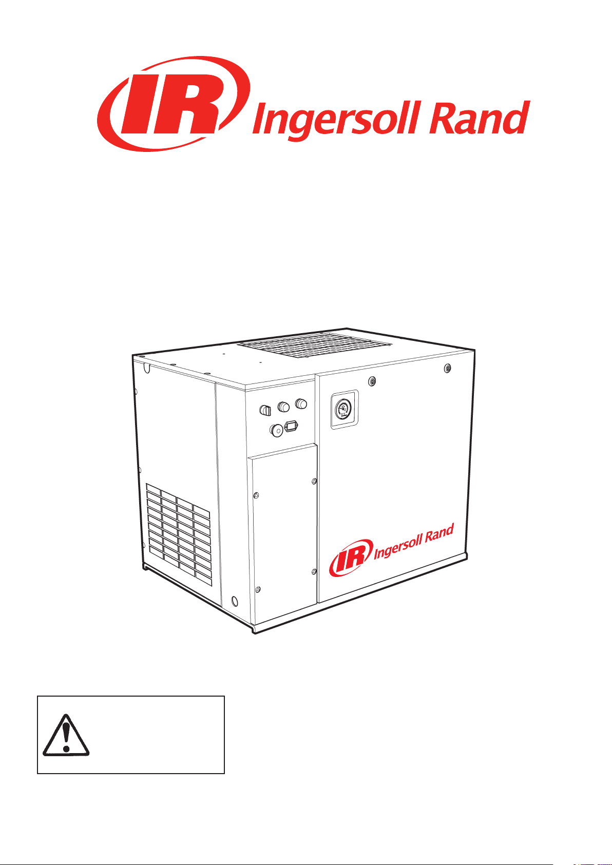
SSR UP5-4, UP5-5.5, UP5-7.5, UP5-11c
50 Hz
SSR UP6-5, UP6-7.5, UP6-10, UP6-15c
60 Hz
MANUAL DE MANEJO Y MANTENIMIENTO
Este manual contiene
importante información sobre
seguridad y ha de ponerse
a disposición del personal
encargado del funcionamiento
y mantenimiento de la
máquina.
Consulte todas las comunicaciones con el distribuidor más cercano de
reparaciones y mantenimiento completo de Ingersoll Rand.
C.C.N. : 80445273 es
REV. : A
FECHA : OUTUBRO 2008
Page 50
GRUPO DE COMPRESORES DE AIRE GARANTIA Y ARRANQUE
REGISTRADO
Garantía
La Compañía garantiza que el equipo por ella fabricado será y entregado en virtud de la presente estará exento de
defectos de materiales y de mano de obra durante un período de doce meses a partir de la fecha de puesta en
funcionamiento o de dieciocho meses a partir de la fecha de despacho desde la fábrica, si ésta ocurriese primero.
El Comprador estará obligado a informar por escrito y con prontitud cualquier fallo de conformidad de esta garantía
a la Compañía dentro del citado período, con lo cual la Compañía subsanará, a discreción propia, tal disconformidad
mediante la reparación adecuada del equipo o suministrando una pieza de repuesto F.O.B. punto de embarque,
siempre que el Comprador haya almacenado, instalado, mantenido y operado tal Equipo de conformidad con las
nuevas prácticas de la industria y haya cumplido las recomendaciones especícas de la Compañía.
Los accesorios o el equipo suministrado por la Compañía, pero fabricado por otros, se beneciará de cualquier
garantía que los fabricantes hayan proporcionado a la Compañía y que pueda trasladarse al Comprador. La Compañía
declinará toda responsabilidad acerca de cualesquiera reparaciones, recambios o ajustes realizados en el equipo y
de cualesquiera costos de la mano de obra realizada por el Comprador o por otros, sin previo consentimiento por
escrito de la Compañía.
Se excluyen especícamente los efectos de corrosión y el uso y desgaste normales. Las garantías de rendimiento
se limitan a aquéllos que se indiquen especícamente en la propuesta de la Compañía. A menos que la
responsabilidad de cumplir tales garantías de rendimiento se limite a pruebas especícas, la obligación de la
Compañía será la de subsanar de la forma y durante el período de tiempo que anteriormente se indica.
LA COMPAÑÍA NO CONCEDE GARANTIA O REPRESENTACION ALGUNA DE NINGUN TIPO EN ABSOLUTO,
EXPRESA O IMPLICITA, SALVO LA DEL TITULO, Y POR LA PRESENTE RENUNCIA A T ODAS LAS GARANTIAS
DE COMERCIABILIDAD E IDONEIDAD PARA UN PROPOSITO EN PARTICULAR.
La corrección por la Compañía de disconformidades, sean patentes o latentes, de la forma y por el período de tiempo
anteriormente indicados constituirá el cumplimiento de todas las responsabilidades de la Compañía en cuanto a tales
disconformidades bien sean que se basen en un contrato, negligencia de garantía, indemnización, responsabilidad
estricta o de otro modo con respecto a o emanantes de tal Equipo.
El Comprador no operará el Equipo que se considere defectuoso, sin noticar previamente por escrito a la Compañía
su intención de realizar esto. Cualquier utilización tal del Equipo se llevará a cabo bajo el riesgo y responsabilidad
exclusivos del Comprador.
Obsérvese que ésta es la garantía normal de Ingersoll Rand. Toda garantía en vigor en el momento de la compra
del compresor o negociada como parte del pedido de compra puede tener prioridad sobre esta garantía.
Para registrarse en línea, entrar en http://air.ingersollrand.com
Ingersoll Rand
Industrial Air Solutions
Swan Lane
Hindley Green
Wigan WN2 4EZ
Ingersoll Rand Asia Pacic
C/O Ingersoll Rand South East Asia (Pte) Ltd.
42 Benoi Road
Singapore 629903
Ingersoll Rand
Industrial Air Solutions
P.O. Box 1840
800–D Beaty Street
Davidson, NC 28036
Page 51

Manual De Manejo Y Mantenimiento Contenido
CONTENTS
PREAMBULO . . . . . . . . . . . . . . . . . . . . . . . . . . . . . . . . . . . . . . . . . . . . . . 6
CALCOMANIAS. . . . . . . . . . . . . . . . . . . . . . . . . . . . . . . . . . . . . . . . . . . . . 7
SIMBOLOS ISO. . . . . . . . . . . . . . . . . . . . . . . . . . . . . . . . . . . . . . . . . . . . 7
FORMA GRAFICA Y SIGNIFICADO DE LOS SIMBOLOS ISO. . . . . . . . . . . . . . . 7
SIMBOLOS ANSI. . . . . . . . . . . . . . . . . . . . . . . . . . . . . . . . . . . . . . . . . . . 10
FORMA GRAFICA Y SIGNIFICADO DE LOS SIMBOLOS ANSI. . . . . . . . . . . . . . 10
SECURITE . . . . . . . . . . . . . . . . . . . . . . . . . . . . . . . . . . . . . . . . . . . . . . . . 13
Información general . . . . . . . . . . . . . . . . . . . . . . . . . . . . . . . . . . . . . . . 13
Aire comprimido . . . . . . . . . . . . . . . . . . . . . . . . . . . . . . . . . . . . . . . . . . 13
Productos . . . . . . . . . . . . . . . . . . . . . . . . . . . . . . . . . . . . . . . . . . . . . . 14
Transporte . . . . . . . . . . . . . . . . . . . . . . . . . . . . . . . . . . . . . . . . . . . . . 14
Sistema eléctrico . . . . . . . . . . . . . . . . . . . . . . . . . . . . . . . . . . . . . . . . . . 14
Eliminación del condensado . . . . . . . . . . . . . . . . . . . . . . . . . . . . . . . . . . 14
INFORMACION GENERAL . . . . . . . . . . . . . . . . . . . . . . . . . . . . . . . . . . . . . . 15
CONDUCTOS E INSTRUMENTACION . . . . . . . . . . . . . . . . . . . . . . . . . . . . . . 15
ESQUEMA ELÉCTRICO UP6 5–15 HP VOLTAJE TOTAL (FV) TRIFÁSICO
60 Hz ARRANQUE DIRECTO (DOL) – EE.UU. . . . . . . . . . . . . . . . . . . . . . . . . . 17
ESQUEMA ELÉCTRICO UP6 5–15 HP VOLTAJE TOTAL (SD) TRIFÁSICO 60 Hz . . . . 18
ESQUEMA ELÉCTRICO UP6 5–15 HP VOLTAJE TOTAL (FV) MONOFÁSICO
60 Hz – EE.UU. . . . . . . . . . . . . . . . . . . . . . . . . . . . . . . . . . . . . . . . . . . 19
ESQUEMA ELÉCTRICO UP5 5–15 HP VOLTAJE TOTAL (FV) TRIFÁSICO
50 Hz ARRANQUE DIRECTO (DOL) . . . . . . . . . . . . . . . . . . . . . . . . . . . . . . . 20
ESQUEMA ELÉCTRICO UP5 5–15 HP VOLTAJE TOTAL (SD) TRIFÁSICO
50 Hz ARRANQUE DIRECTO . . . . . . . . . . . . . . . . . . . . . . . . . . . . . . . . . . . 21
INSTALACIÓN / MANEJO . . . . . . . . . . . . . . . . . . . . . . . . . . . . . . . . . . . . . . 22
DESEMBALAJE . . . . . . . . . . . . . . . . . . . . . . . . . . . . . . . . . . . . . . . . . . . 23
MONTAODS EN TANQUES (80 GALONES) . . . . . . . . . . . . . . . . . . . . . . . . . . 24
DESEMBALAJE . . . . . . . . . . . . . . . . . . . . . . . . . . . . . . . . . . . . . . . . . . . 25
MONTAODS EN TANQUES (120 GALONES) . . . . . . . . . . . . . . . . . . . . . . . . . . 26
DESEMBALAJE . . . . . . . . . . . . . . . . . . . . . . . . . . . . . . . . . . . . . . . . . . . 27
MONTAODS EN TANQUES (272 LITRES) . . . . . . . . . . . . . . . . . . . . . . . . . . . . 28
DESEMBALAJE . . . . . . . . . . . . . . . . . . . . . . . . . . . . . . . . . . . . . . . . . . . 29
MONTAODS EN TANQUES (500 LITRES) . . . . . . . . . . . . . . . . . . . . . . . . . . . . 30
DESEMBALAJE . . . . . . . . . . . . . . . . . . . . . . . . . . . . . . . . . . . . . . . . . . . 31
UBICACION EN LA PLANTA. . . . . . . . . . . . . . . . . . . . . . . . . . . . . . . . . . . . 32
TUBERIA DE DESCARGA . . . . . . . . . . . . . . . . . . . . . . . . . . . . . . . . . . . . . 32
CARACTERISTICAS ELECTRICAS . . . . . . . . . . . . . . . . . . . . . . . . . . . . . . . . 37
INSTRUCCIONES DE OPERACION . . . . . . . . . . . . . . . . . . . . . . . . . . . . . . . . . 38
FUNCIONAMIENTO GENERAL TION . . . . . . . . . . . . . . . . . . . . . . . . . . . . . . 38
MANDOS DEL COMPRESOR . . . . . . . . . . . . . . . . . . . . . . . . . . . . . . . . . . . 39
http://air.ingersollrand.com 3
Page 52

Contenido Manual De Manejo Y Mantenimiento
CONTROL DE ARRANQUE Y PARADA AUTOMÁTICO . . . . . . . . . . . . . . . . . . . . 39
CONTROL DOBLE . . . . . . . . . . . . . . . . . . . . . . . . . . . . . . . . . . . . . . . . . . 39
ANTES DEL ARRANQUE . . . . . . . . . . . . . . . . . . . . . . . . . . . . . . . . . . . . . . 40
ARRANQUE . . . . . . . . . . . . . . . . . . . . . . . . . . . . . . . . . . . . . . . . . . . . . 40
PARADA NORMAL/DE EMERGENCIA . . . . . . . . . . . . . . . . . . . . . . . . . . . . . 40
MANTENIMIENTO . . . . . . . . . . . . . . . . . . . . . . . . . . . . . . . . . . . . . . . . . . . 41
MANTENIMIENTO DE RUTINA . . . . . . . . . . . . . . . . . . . . . . . . . . . . . . . . . . 42
PROCEDIMIENTO PARA RESTABLECER EL NIVEL DEL REFRIGERANTE. . . . . . . . . 43
PROCEDIMIENTO DE CAMBIO DEL REFRIGERANTE . . . . . . . . . . . . . . . . . . . . 43
PROCEDIMIENTO DE CAMBIO DEL FILTRO DE REFRIGERANTE . . . . . . . . . . . . . 44
PROCEDIMIENTO DE CAMBIO DEL ELEMENTO DEL FILTRO . . . . . . . . . . . . . . . 44
PROCEDIMIENTO DE SUSTITUCIÓN DEL ELEMENTO SEPARADOR . . . . . . . . . . . 44
PROCEDIMIENTO DE LIMPIEZA DEL REFRIGERADOR . . . . . . . . . . . . . . . . . . . 44
PROCEDIMIENTO DE VERIFICACION Y AJUSTE DE CORREAS . . . . . . . . . . . . . . 44
VÁLVULA ELÉCTRICA DE VACIADO (OPCIONAL) . . . . . . . . . . . . . . . . . . . . . . 45
DESCRIPCION DEL PRODUCTO . . . . . . . . . . . . . . . . . . . . . . . . . . . . . . . 45
FUNCIONAMIENTO . . . . . . . . . . . . . . . . . . . . . . . . . . . . . . . . . . . . . . . 45
AJUSTES DEL TEMPORIZADOR . . . . . . . . . . . . . . . . . . . . . . . . . . . . . . . 46
LOCALIZACION DE FALLOS . . . . . . . . . . . . . . . . . . . . . . . . . . . . . . . . . . 46
MANTENIMIENTO. . . . . . . . . . . . . . . . . . . . . . . . . . . . . . . . . . . . . . . . 46
MANTENIMIENTO PREVENTIVO . . . . . . . . . . . . . . . . . . . . . . . . . . . . . . . . 46
MANTENIMEINTO DEL SEPARADOR DE LA HUMEDAD . . . . . . . . . . . . . . . . . . 46
MANTENIMIENTO DEL FILTRO DE AIRE . . . . . . . . . . . . . . . . . . . . . . . . . . . . 47
DESMONTAJE DE LA UNIDAD . . . . . . . . . . . . . . . . . . . . . . . . . . . . . . . . . . 47
FUGAS DE REFRIGERANTE EN EL CIRCUITO DE REFRIGERACION . . . . . . . . . . . . 48
CARGA DE REFRIGERANTE . . . . . . . . . . . . . . . . . . . . . . . . . . . . . . . . . . . . 48
CARACTERISTICAS DEL REFRIGERANTE R134A . . . . . . . . . . . . . . . . . . . . . . . 48
LOCALIZACION DE FALLOS. . . . . . . . . . . . . . . . . . . . . . . . . . . . . . . . . . . . 48
MANTENIMIENTO . . . . . . . . . . . . . . . . . . . . . . . . . . . . . . . . . . . . . . . . . 48
RESOLUCION DE AVERIAS . . . . . . . . . . . . . . . . . . . . . . . . . . . . . . . . . . . . . 50
4 http://air.ingersollrand.com
Page 53

Manual De Manejo Y Mantenimiento Contenido
ABREVIATURAS Y SIMBOLOS
#### Para el número de derie, sirvanse contactar con Ingersoll Rand
->#### Hasta serie nº
####-> Desde serie nº
* No dibujado
† Opcion
NR No necesario
AR Según se necesite
SM Sitemaster/Sitepack
HA Máquina para ambiente severo
WC Máquina refrigerada por agua
AC Máquina refrigerada por aire
ERS Sistema de recuperación de energía
T.E.F.C.
O.D.P. (motor) Abierto a prueba de goteo
ppm partes por millón
Motor totalmente blindado refrigerado por aire (IP54)
http://air.ingersollrand.com 5
Page 54

MANUAL DE MANEJO Y MANTENIMIENTO PREAMBULO
PREAMBULO
El contenido de este manual es propiedad y material
condencial de Ingersoll Rand y no puede reproducirse
sin el consentimiento previo por escrito de Ingersoll
Rand.
Ninguna parte de lo contenido en este documento
puede entenderse como promesa, garantía o
representación, implícita o explícita, respecto a los
productos Ingersoll Rand que en él se describen. Tales
garantías u otros términos y condiciones de venta de los
productos deberán estar deacuerdo con los términos y
condiciones estándar de venta para tales productos, que
están a disposición de los clientes si lo solicitan.
Este manual contiene instrucciones y datos técnicos
para todas las operaciones de empleo normales y de
mantenimiento rutinario. Las reparaciones mayores
no están comprendidas en este manual y deben
encomendarse o consultarse a un concesionario de
servicio autorizado Ingersoll Rand.
El diseño de esta máquina se ha certicado que satisface
directrices de la Comunidad Europea. Cualquier
modicación de la máquina o parte alguna sería
inadmisible, e invalidaría la certicación y las marcas
designatorias de directrices de la C.E.
Todos los componentes, accesorios, tuberías y
conectores incorporados al sistema de aire comprimido,
deberán ser:
de buena calidad, adquiridos a un fabricante de
•
buena reputación y, en lo posible, de un tipo
aprobado por Ingersoll Rand.
claramente de un régimen adecuado para una
•
presión igual, como mínimo, a la máxima presión
de trabajo premisible de la máquina.
compatibles con el lubricante/ refrigerante del
•
compresor.
acompañados de instrucciones para que su
•
instalación, funcionamiento y mantenimiento se
lleven a cabo con seguridad.
Los departamentos de Servicio de Ingersoll Rand puede
facilitar detalles de los equipos aprobados.
El empleo de piezas para reparaciones no genuinas y
distintas a las incluidas en las listas de piezas aprobadas
por Ingersoll Rand, puede originar condiciones de
riesgo sobre las que Ingersoll Rand no tiene control
alguno. Por consiguiente, Ingersoll Rand declina toda
responsabilidad acerca de equipos en los que no se
instalen piezas aprobadas. Pueden verse afectadas las
condiciones generales de garantía.
Los usos para lo que esta diseñada esta máquina estan
subrayados abajo y también se dan algunos ejemplos
de uso incorrecto, sin embargo Ingersoll Rand no
se ouede anticipar a cada aplicación o situación de
trabajo que pueda ocurrir.
SI TIENE DUDAS CONSULTE AL SUPERVISOR.
Esta máquina se ha concebido y suministrado para su
utilización únicamente bajo las condiciones y en las
aplicaciones especicadas a continuación:
Compresión de aire de ambiente normal
•
sin gases, vapores o partículas adicionales
conocidos o detectables.
Funcionamiento dentro de la gama de
•
temperatura ambiente especicada en la
sección INFORMACION GENERAL de este
manual.
Uso de la máquina en cualquiera de las siguientes
situaciones:–
No esta aprobado por Ingersoll Rand.
a.
Puede perjudicar la seguridad de los
b.
usuarios y otras personas, y
Puede perjudicar cualquier reclamacion
c.
hacha contra Ingersoll Rand.
TABLA 1
Uso de la máquina para producir aire comprimido
para:
consumo humano directo
a.
consumo humano indirecto, sin el
b.
correspondiente ltrado y puricado.
Uso de la máquina fuera del rango de temperatura
ambiente especicado en la sección de INFORMACION
GENERAL de este manual.
Uso de la máquina donde haya riesgo real o potencial
de niveles peligrosos de gases o vapores inamables.
ESTA MÁQUINA NI SE HA DESTINADO NI DEBE
UTILIZARSE EN AMBIENTES POTENCIALMENTE
EXPLOSIVOS, INCLUIDAS LAS SITUACIONES EN LAS
QUE SE HALLEN PRESENTAS GASES O VAPORES
INFLAMABLES.
Uso de la máquina con componentes no aprobados
por Ingersoll Rand.
Uso de la máquina con componentes de seguridad o
de control perdidos o averiados.
La compañia no acepta resposabilidades por arrores en
la traducción de la versión original en Inglés.
Ingersoll Rand se reserva el derecho a realizar cambios
y mejoras de los productos sin previo aviso y sin incurrir
en ningún tipo de obligación a realizar tales cambios o
añadir tales mejoras en aquellos productos que se hayan
vendido previamente.
© COPYRIGHT 2008
INGERSOLL RAND
http://air.ingersollrand.com 6
Page 55
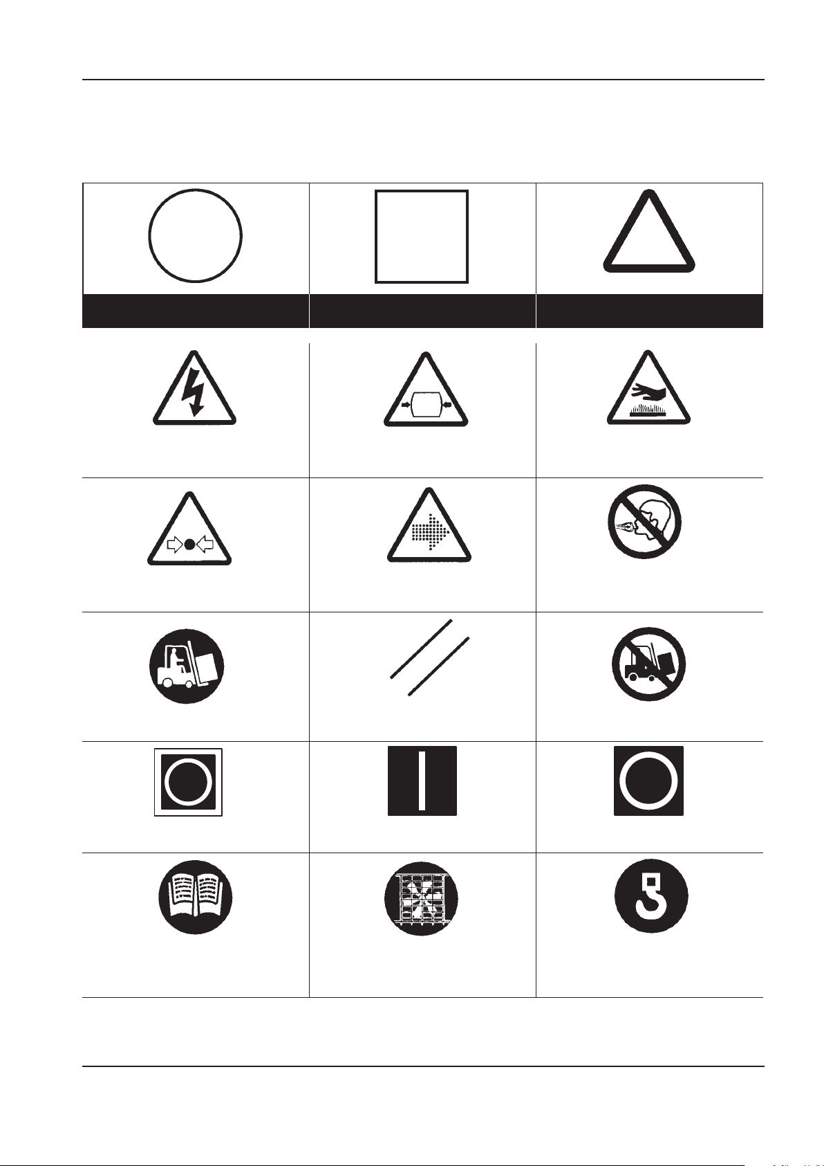
MANUAL DE MANEJO Y MANTENIMIENTO CALCOMANIAS
Prohibición/Obligatoriedad Información/Instrucciones Advertencia
ADVERTENCIA – Riesgo de descarga
eléctrica.
ADVERTENCIA – Recipiente presurizado.
ADVERTENCIA – Supercie caliente.
ADVERTENCIA – Sistema o componente
presurizado.
ADVERTENCIA – Caudal de aire/gas – o
descarga de aire.
No respirar el aire comprimido de esta unidad.
Utilizar la carretilla elevadora en esta lado. REPOSICIONAR No utilizar la carretilla elevadora en esta lado.
)aigrene( odidnecnE.aicnegreme ed adaraP Apagado (energia).
Antes de operar o llevar a cabo ningún
mantenimiento, leer el manual de operaciòn y
mantenimiento de esta máquina.
No operar la máquina sin que la protección
este jada.
Punto de elevación.
CALCOMANIAS
SIMBOLOS ISO
FORMA GRAFICA Y SIGNIFICADO DE LOS SIMBOLOS ISO
http://air.ingersollrand.com 7
Page 56

8 http://air.ingersollrand.com
CALCOMANIAS MANUAL DE MANEJO Y MANTENIMIENTO
ERIA ED AGRACSEDNOICATOR FILTRO DEL REFRIGERANTE
REARRANQUE AUTOMA OTNEIMINETNAMOCIT MANUTENZIONE PROIBITA
CONDUCTO DE VACIADO DEL
REFRIGERANTE
CONDUCTO DE VACIADO DEL
CONDENSADO
FILTRO
FRAGIL MANTENER SECO COLOCAR EN ESTA POSICION
NO USAR GANCHOS
NO USAR MORDAZAS DE AGARRE
LATERAL
HORAS
ENERGIA ELECTRICA INSPECCIONAR
Riesgo de punto de aplastamiento.
Mantener las manos alejadas.
Page 57
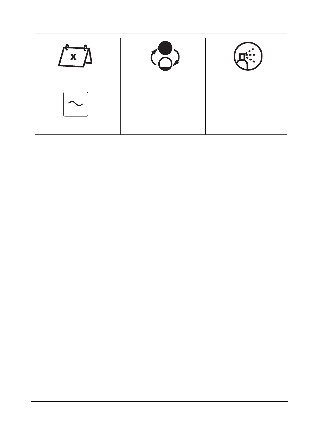
MANUAL DE MANEJO Y MANTENIMIENTO CALCOMANIAS
Cada x meses, si lo requieren más pronto por
Las horas de funcionamiento
CAMBIAR / MONTAR DE NUEVO LIMPIAR.
ENTRADA DE ENERGIA ELECTRICA (AC)
http://air.ingersollrand.com 9
Page 58
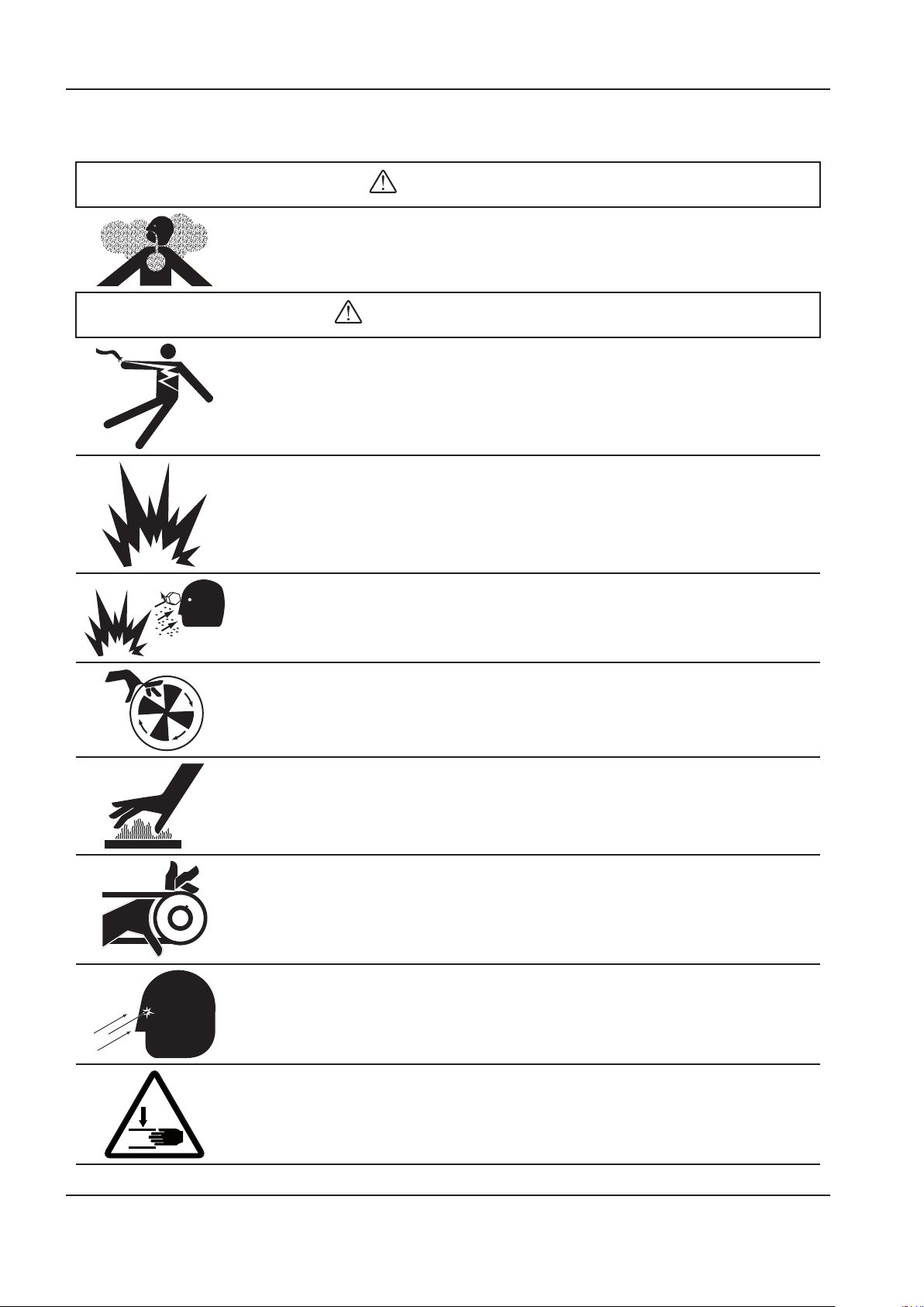
10 http://air.ingersollrand.com
CALCOMANIAS MANUAL DE MANEJO Y MANTENIMIENTO
PELIGRO
ADVERTENCIA
SIMBOLOS ANSI
FORMA GRAFICA Y SIGNIFICADO DE LOS SIMBOLOS ANSI
AIRE DE ADMISIÓN. Puede contener monóxido de carbono u otros contaminantes. Puede
causar lesiones graves o la muerte. Los compresores de aire Ingersoll Rand no están diseñados,
destinados para aire respirable. No se debe usar el aire comprimido para aplicaciones de aire
respirable a menos que se trate de acuerdo con todas las normas y reglamentos correspondientes.
VOLTAJE PELIGROSO. Puede causar lesiones graves o la muerte. Desconecte la energía y descargue
la presíon del tanque antes de darle servicio. Bloquear/etiquetar la máquina. El compresor debe
estar conectado a un circuito adecuadamente puesto a tierra. Ver las instruccciones de puesta a
tierra en el manual. No haga funcionar el compresor en ambientes húmedos. Debe almacenarse en
el interior.
RIESGO DE INCENDIO O EXPLOSIÓN. El arco eléctrico producido por los componentes del
compresor puede encender los líquidos y vapores inamables, causando lesiones graves. No haga
funcionar nunca el compresor cerca de líquidos o vapores inamables. Si se utiliza para aspersión
de materiales inamables, debe mantenerse el compresor a una distancia mínima de 20 pies (6
metros) del área de aspersión.
AIRE A ALTA PRESÍON. Los tanques oxidados pueden producir una explosión y lesiones graves o la
muerte. Receptor bajo presión. Antes de efectuar el mantenimiento, el operador deberá reducir la
presión del tanque. A demás del drenaje automático, haga funcionar la válvula manual de desagüe
una vez por semana. La válvula manual de drenaje está ubicada en la parte inferior del tanque.
PARTES MÓVILES. Puede causar lesiones graves. No opere la máquina si se ha retirado el protector.
La máquina puede empezar a funcionar automáticamente. Desconecte la energía ante de darle
servicio a la máquina. Bloquear/etiquetar la máquina.
SUPERFICIE CALIENTE. Puede causar lesiones graves. No tocar. Deje que se enfríe antes de dar
servicio. No toque el compresor ni las tuberías calientes.
Correas y poleas expuestas.
Pueden causar heridas severas o muerte.
No opere con las cubiertas fuera de su lugar. Desconecte el suministro electrico, asegure el
interruptor y marquelo antes de dar mantenimiento.
El ujo de escape puede expulsar desechos en suspensión.
Debe usarse protección de seguridad en todo momento.
Riesgo de punto de aplastamiento.
Mantener las manos alejadas.
Page 59
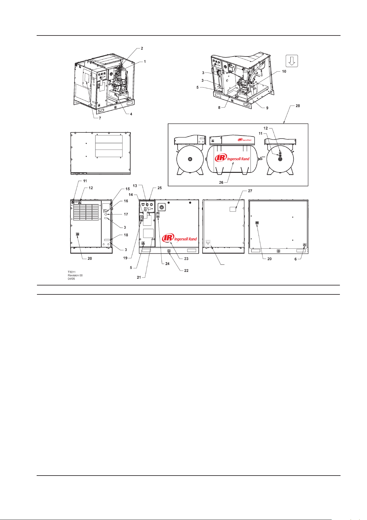
MANUAL DE MANEJO Y MANTENIMIENTO CALCOMANIAS
29
Elemento ccn Cantidad Descripción Elemento ccn Cantidad Descripción
1 93166502 1
2 92867530 1
3 3 Calcomanía, voltaje
4 93166460 1
5 92960593 2
6 93166478 1
7 22530331 1
8 23353196 1
9 92930585 1 Calcomanía, recipiente 18 22604276 1
10 93165983 1 Calcomanía, dirección de
11 92867407 2 Calcomanía, no inhalar
Etiqueta, elemento de
repuesto
Etiqueta, advertencia de
supercie caliente
Calcomanía, desagüe de
refrigerante
Calcomanía, advertencia
tensión peligrosa
Calcomanía, vaciado del
condensado
Calcomanía, instrucción
de derivación del secador
Calcomanía, piezas de
mantenimiento
presurizado
rotación 19 93493641 1
12 92867498 1
13 22547145 1
14 22459200 1 Etiqueta, rotación
15 SPEC 1
16 93166486 1
17 22141311 1
Etiqueta, aviso de descarga
de aire Montaje sobre la
base únicamente
Calcomanía, sistema de aire
completo Sólo paquetes de
secador
Especicaciones, unidad
del compresor
Calcomanía, entrada de
energía eléctrica
Calcomanía, para cubrir
oricio
Calcomanía, circuito de
cableado múltiple
Sólo paquetes de secador
Calcomanía, aviso de
arranque
Contd....
http://air.ingersollrand.com 11
Page 60
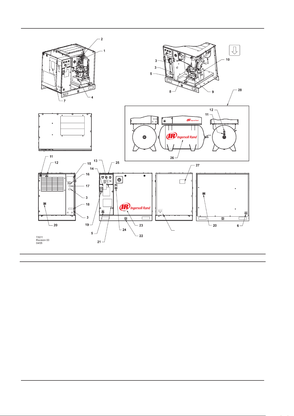
CALCOMANIAS MANUAL DE MANEJO Y MANTENIMIENTO
29
Elemento ccn Cantidad Descripción Elemento ccn Cantidad Descripción
20 93165959 1 Calcomanía, usar
guardas cuando esté en
funcionamiento
21 1 Calcomanía, diagrama
esquemático de cableado
22 93171262 1 Calcomanía, levantar aquí
por ambos lados
Sólo montaje sobre la base
23 22913032 1 Etiqueta, logotipo de
Ingersoll Rand
Montaje sobre el depósito
únicamente
22435713 1 Etiqueta, logotipo de
Ingersoll Rand
Montaje sobre el depósito
únicamente
24 92930668 1 Calcomanía, sin
mantenimiento antes de
consultarel manual
12 http://air.ingersollrand.com
25 22417109 1 Calcomanía, placa frontal
Contador horario
rectangular
22529291 1 Calcomanía, placa frontal
Contador horario
redondo
26 23038474 1 Etiqueta, logotipo de
Ingersoll Rand
27 22454060 1 Calcomanía, correa
28 Opción de montaje sobre
el depósito
29 54618681 1 Calcomanía, vaciado del
condensado
Page 61

MANUEL D’UTILISATION ET D’ENTRETIEN SECURITE
SECURITE
¡PELIGRO!
El riesgo OCASIONARA la MUERTE, GRAVES
LESIONES o importantes daños en los bienes si se
pasa por alto. Las instrucciones deberán respetarse
con precisión para evitar las lesiones o la muerte.
¡ADVERTENCIA!
El riesgo PUEDE ocasionar la MUERTE, GRAVES
LESIONES o importantes daños en los bienes si se
pasa por alto. Las instrucciones deberán respetarse
con precisión para evitar las lesiones o la muerte.
PRECAUCIONES
Las precauciones llaman la atención sobre las
instrucciones que deben seguirse estrictamente
para evitar daños en el equipo, el proceso o sus
alrededores.
AVISOS
Los avisos se utilizan para dar información
suplementaria.
PRECAUCION DE AIRE RESPIRABLE
Los compresores de aire Ingersoll Rand no han
sido concebidos,destinados o aprobados para aire
respirable. El aire comprimido no deberá utilizarse
para aplicaciones de aire respirable, a menos que
sea tratado de conformidad con todos los códigos y
reglamentos aplicables.
INFORMACIÓN GENERAL
Asegúrese de que el operador lea y entienda las
pegatinas y consulte el manual antes de realizar
mantenimiento u operación de la unidad.
Asegúrese de que el Manual de Funcionamiento y
Mantenimiento no se retire permanentemente de la
máquina.
en su lugar y que la capota o las puertas estén cerradas
durante la operación.
Las especicaciones de esta máquina son tales que no
es adecuada para usarla en áreas donde exista riesgo de
gas inamable.
La instalación de este compresor debe estar de acuerdo con
códigos eléctricos reconocidos y con cualquier código local
de Seguridad e Higiene.
El empleo de recipientes de plástico en ltros de
conductos puede resultar peligroso. Su seguridad puede
verse afectada bien sea por lubricantes sintéticos o
por aditivos utilizados en aceites minerales. Ingersoll
Rand recomienda utilizar sólo recipientes de metal en
sistemas sometidos a presión.
AIRE COMPRIMIDO
El aire comprimido puede ser peligroso si no se utiliza
correctamente. Antes de realizar ningún tipo de trabajo
en la unidad, asegúrese de que se ha liberado toda la
presión del sistema y que la máquina no puede arrancar
accidentalmente.
ASVERTENCIA
Imponiendo en el compresor una parada
normal o de emergencia sólo desahogará la
presión aguas arriba de la válvula de presión
mínima encima del tanque separador.
Si se requiere trabajo de mantenimiento
aguas abajo de esta válvula, cerciorarse
de que se desahogue toda la presión en el
punto de ventilación del proceso exterior al
compresor.
Asegúrese que la máquina trabajando a la presión es
conocida por el personal apropiado.
Asegúerese que el personal de mantenimiento esta
entrenado convenientemente y que han leído los
Manuales de Mantenimiento.
No apuntar con boquillas de aire o pulverizadores a
persona alguna.
El aire comprimido y la energía eléctrica pueden ser
peligrosos. Antes de comenzar cualquier trabajo sobre
el compresor, asegurar que la alimentación eléctrica ha
sido cortada y que el compresor ha sido despresurizado.
Utilice protección para los ojos cuando funcione el
compresor o realice trabajos de mantenimiento en el
mismo.
Todas las personas situadas cerca de maquinaria en
funcionamiento deberán llevar protección para los
oídos y recibir instrucciones sobre su modo de empleo
de conformidad con la legislación sobre seguridad en el
lugar de trabajo.
Asegúrese de que todas las cubiertas protectoras estén
Todo el equipo de presión de aire instelado o conectado
a la máquina tienen que funcionar a presiones de
trabajo de seguridad o al menos a la presión de tarado
de la máquina.
Si se conecta más de un compresor a una planta
común aguas abajo, deberán instalarse y controlarse
por procedimientos de trabajo válvulas de aislamiento
ecaces, de forma que una máquina no sea sometida a
presión / sobrepresión accidentalmente por otra.
El aire comprimido no tiene que usarse directamente
por ningún aparato de respiración o máscara.
El aire descargado contiene un porcentaje muy pequeño
de aceite lubricante del compresor y se deberá tener
cuidado de que sea compatible el equipo situado aguas
abajo.
Si el aire de descarga se va a liberar en un espacio
reducido, debe proporcionarse una ventilación
adecuada.
http://air.ingersollrand.com 13
Page 62

SECURITE MANUEL D’UTILISATION ET D’ENTRETIEN
Cuando se emplee aire comprimido, el personal deberá
llevar un equipo de protección adecuado.
Todas las piezas sometidas a presión, especialmente
tubos exibles y sus acoplamientos, tienen que ser
inspeccionados regularmente, no tener ningún defecto
y han de ser sustituídos de acuerdo al Manual de
instrucciones.
El aire comprimido puede ser peligroso si no se utiliza
correctamente. Antes de realizar ningún tipo de trabajo
en la unidad, asegúrese de que se ha liberado toda la
presión del sistema y que la máquina no puede arrancar
accidentalmente.
Evite el contacto de cualquier parte del cuerpo con el
aire comprimido.
Deberá comprobarse periódicamente el funcionamiento
de todas las válvulas de seguridad situadas en el tanque
separador.
No someter a presión excesiva al tanque colector o a
recipientes similares superando los límites de diseño.
No usar un tanque colector ni recipientes similares que
no cumplan los requisitos de diseño del compresor.
Sírvanse contactar con el distribuidor si se precisa
asistencia.
No taladrar, soldar o alterar de otro modo el tanque
colector o recipientes similares.
Antes de realizar el servicio a la unidad, ventilar la
presión antes de eliminar la corriente para asegurarse de
que la indicador dé una lectura de presión cero.
PRODUCTOS
El equipo de elevación ha de tener capacidad adecuada
para el peso del compresor.
No trabajar ni pasar por debajo del compresor mientras
esté suspendido.
SISTEMA ELÉCTRICO
Mantener alejados del sistema eléctrico del compresor
todas las partes del cuerpo y las herramientas de mano
u otros objetos conductores. Mantener los pies sobre
un suelo seco y estar en pie sobre supercies aislantes y
no entrar en contacto con parte alguna del compresor
cuando se realicen ajustes o reparaciones en partes
expuestas con corriente del sistema eléctrico del
compresor.
ADVERTENCIA
Any electrical connections or adjustments
should only be made by a suitably qualied
electrician
Cerrar y bloquear con lave todas las puertas de acceso
cuando el compresor quede desatendido.
No utilizar extintores destinados a incendios de la Clase
A o Clase B cuando se trate de incendios eléctricos.
Utilizar solamente extintores idóneos para incendios de
la clase AB o de la clase ABC.
Efectuar reparaciones únicamente en zonas limpias,
secas, bien iluminadas y ventiladas.
Conectar el compresor únicamente a sistemas eléctricos
que sean compatibles con sus características eléctricas y
que sean de su capacidad nominal.
Las siguientes substancias han sido utilizadas en la
fabricación de esta máquina y pueden ser peligrosas
para la salud si se utilizan incorrectamente:–
grasa conservante
•
inhibidor de óxido
•
refrigerante
•
EVITE LA INGESTION, EL CONTACTO CON LA PIEL Y
LA INHALACION DE HUMOS
TRANSPORTE
Cuando se transporte o carque una máquina, asegurarse
que se usan los puntos especícos de elevación y de
remolque.
ELIMINACIÓN DEL CONDENSADO
Dado que las normas sobre aguas residuales
varían entre países y regiones, el usuario tiene la
responsabilidad de establecer los límites y respetar las
normas de su zona en particular. Ingersoll–Rand y sus
distribuidores correspondientes se complacerían en
asesorar y ayudar en estos aspectos.
Para más amplia información, consultar la Hoja de Datos
de Materiales para Refrigerante ULTRA.
14 http://air.ingersollrand.com
Page 63
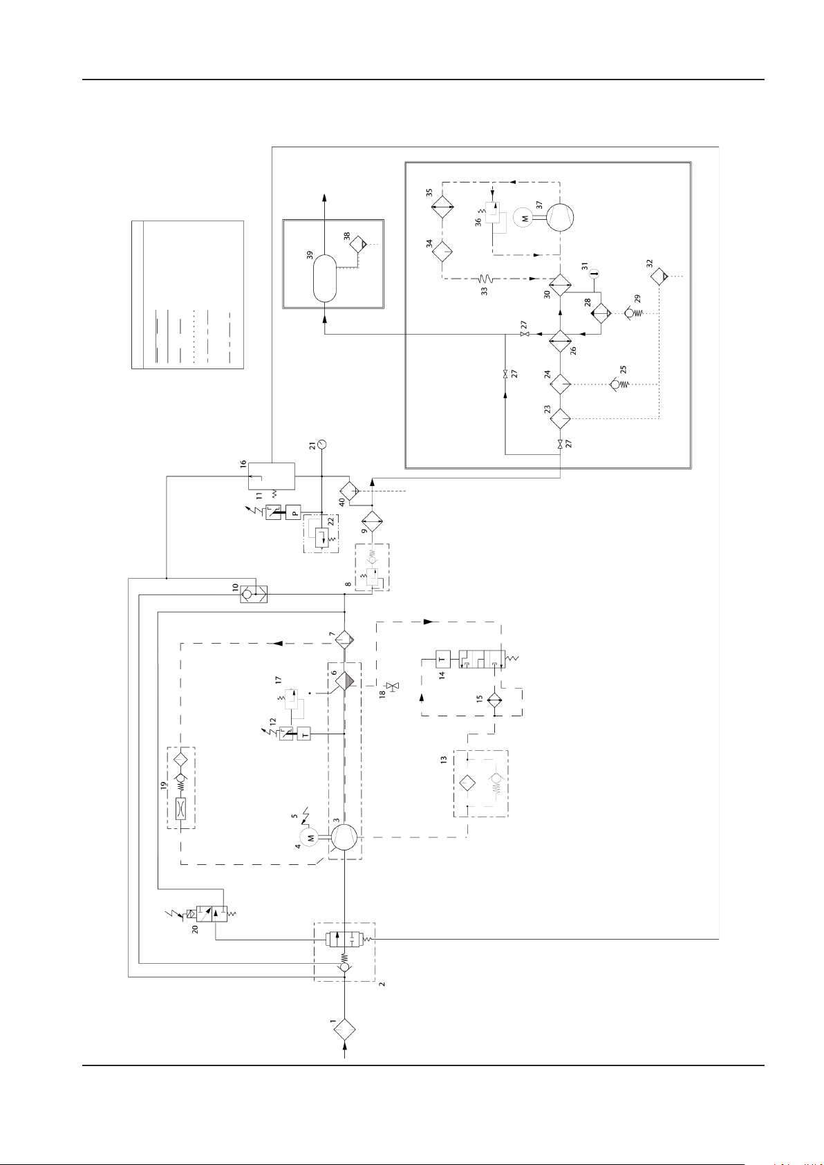
MANUEL D’UTILISATION ET D’ENTRETIEN INFORMACION GENERAL
22426035
REV F
Aire/Líquido refr
iger
ante
Aire
Líquido refr
iger
ante
Líquido condens
ado
Límit
e de
componen
te
s
Refrigeran
te
Recipien
t
e de
almacen
amien
to de aire (opcion
al)
Le
yenda de tuber
ías
sólo
para
S
/D
Secado
r Integrado (opcio
nal)
INFORMACION GENERAL
CONDUCTOS E INSTRUMENTACION
http://air.ingersollrand.com 15
Page 64

16 http://air.ingersollrand.com
INFORMACION GENERAL MANUEL D’UTILISATION ET D’ENTRETIEN
CLAVE
1 Filtro de aire 21 Manómetro
2 Válvula entrada 22 Válvula de seguridad (sirc)
3 Conjunto unidad compresora 23 Filtro de aire, utilización general
4 Motor 24 Filtro de aire de gran ecacia
5 Relé de sobrecarga Motor 25 Válvula de retención
6 Tanque, separador – basto 26 Recuperador
7 Separador, Fino 27 Válvula de aislamiento (opcional)
8 Válvula de presión mínima 28 Separador de humedad
9 Post–enfriador 29 Válvula de retención
10 Válvula de seguridad 30 Evaporador
11 Presostato 31 Indicador de punto de rocío
12 Interruptor de temperatura 32 Válvula de condensado
13 Filtro del refrigerante 33 Tubo capilar
14 Termostato 34 Filtro secador, refrigerante
15 Enfriador 35 Condensador
16 Válvula del piloto 36 Válvula de derivación de gas caliente
17 Válvula de seguridad 37 Compresor, refrigerante
18 Válvula de vaciado 38 Válvula de drenaje automática
19 Pantalla, barrido 39 Depósito de aire
20 Válvula de solenoide 40 Filtro
Page 65
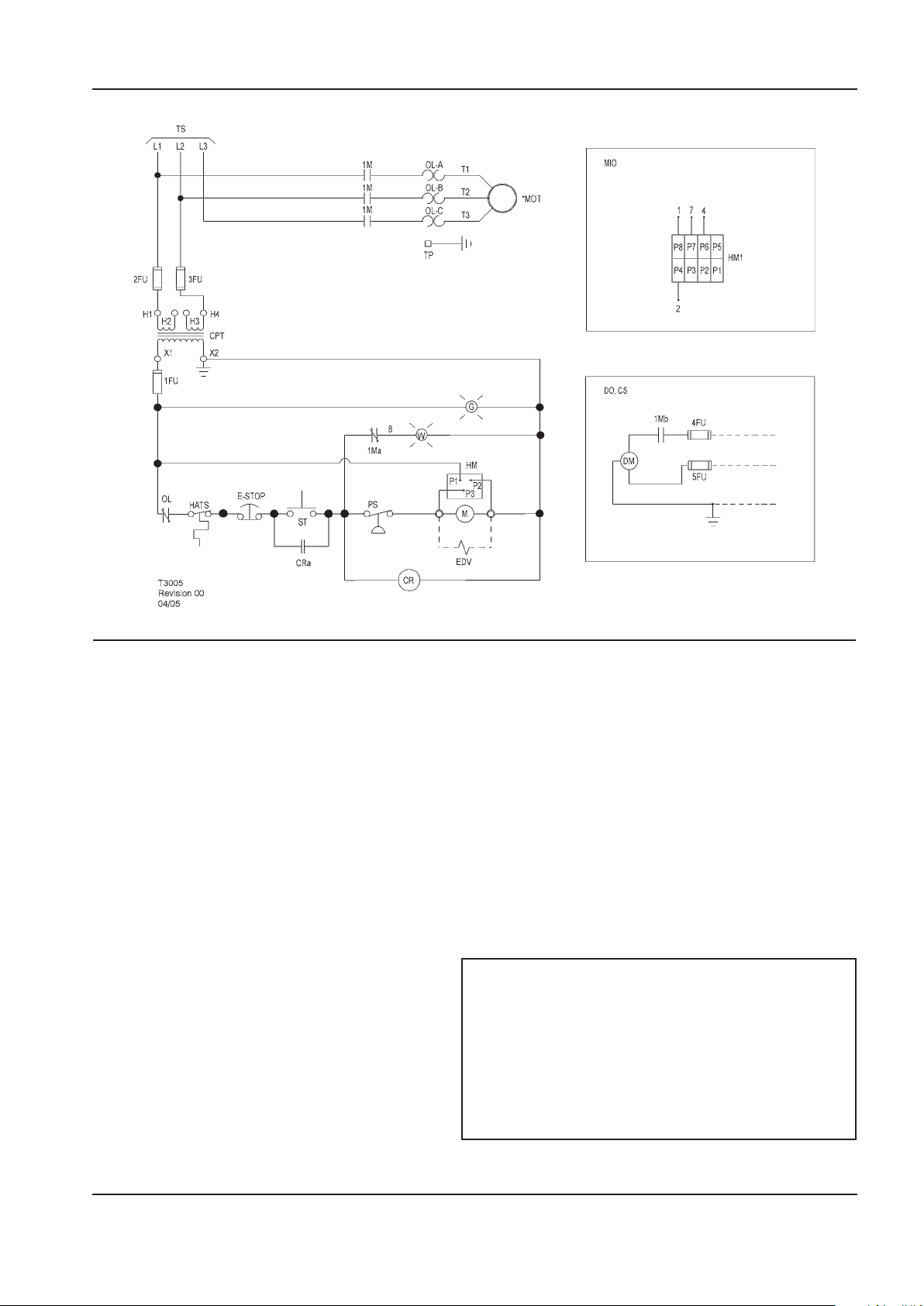
MANUEL D’UTILISATION ET D’ENTRETIEN INFORMACION GENERAL
ESQUEMA ELÉCTRICO UP6 5–15 HP VOLTAJE TOTAL (FV) TRIFÁSICO 60 Hz ARRANQUE DIRECTO (DOL) – EE.UU.
CLAVE
1FU,
2FU, 3FU
4FU, 5FU Fusible M Motor de arranque de la bobina
1Ma Contacto del motor de arranque auxiliar MIO Indicador, mantenimiento opcional(en lugar del
1Mb Contacto del motor de arranque auxiliar MOT Motor
CPT Transformador de control 120/1/50–60
CR Relé de control PS Interruptor de presión
CRa Contacto del relé de control ST Botón de inicio
CS Suministrado por el cliente 115 V/1 Ø/60 Hz TP Puntos terminales
DO Opción de secador TS Al suministro
DM Motor del secador W Luz de espera
EDV Válvula de purga eléctrica 120/1/50–60
E-STOP Botón, parada de emergencia 1. (*) Suministrado, montado y cableado fuera del
G Luz de encendido 2. El circuito se muestra en posición normal
HM Contador horario 3. Deben marcarse todos los cables de acuerdo con
HM1 Indicador, mantenimiento 4. Todos los cables deben estar en conformidad con el
Fusible del circuito de control HATS Interruptor, alta temperatura del aire
contador horario estándar)
OL Sobrecarga, arranque del motor
Consultar la placa de identicación del
transformador para conocer los requisitos de
las conexiones del cableado.
NOTAS
panel de control, en caso necesario según el pedido.
desactivado.
este esquema.
NEC (código eléctrico nacional estadounidense).
http://air.ingersollrand.com 17
Page 66
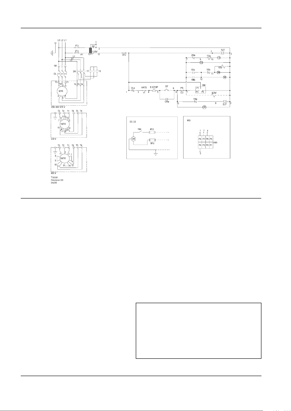
18 http://air.ingersollrand.com
INFORMACION GENERAL MANUEL D’UTILISATION ET D’ENTRETIEN
ESQUEMA ELÉCTRICO UP6 5–15 HP VOLTAJE TOTAL (SD) TRIFÁSICO 60 Hz
CLAVE
1FU, 2FU Fusible primario HATS Interruptor, alta temperatura del aire
3FU Fusible secundario HM Contador horario
4FU, 5FU Fusible del secador HM1 Indicador, mantenimiento
1LT Lámpara, indicadora de encendido (Verde) MIO Indicador, mantenimiento opcional (en lugar del
contador horario estándar)
2LT Lámpara, indicadora de rearranque
automático (Blanca)
1M Contactor, principal OL Sobrecarga, motor principal
1Ma, b, c Contacto auxiliar. Contactor principal OLa Contacto, sobrecarga del motor principal
2M Contactor de triángulo PS Interruptor de presión
2Ma, b Contactos auxiliares. Contactor de
triángulo
1S Contactor de estrella T D Relé, arranque triángulo (10 segundos)
1Sa, b Contactos auxiliares. Contactor de estrella TDc Contacto de relé, retraso desconectado
1SV Válvula de solenoide (NC)
CPT Transformador de control
CR Relé de control 1. (*) Suministrado, montado y cableado fuera del
CRa Contacto del relé de control 2.
CS
DM Motor del secador este esquema.
DO Opción de secador 4. Todos los cables deben estar en conformidad con el
EDV Válvula de drenaje eléctrica (opcional)
E–STOP Botón, parada de emergencia
Suministrado por el cliente 115 V/1 Ø/60 Hz
MTR Motor, compresor
ST Botón de inicio
NOTAS
panel de control, en caso necesario según el pedido.
El circuito se muestra en posición normal desactivado.
3. Deben marcarse todos los cables de acuerdo con
NEC (código eléctrico nacional estadounidense).
Page 67
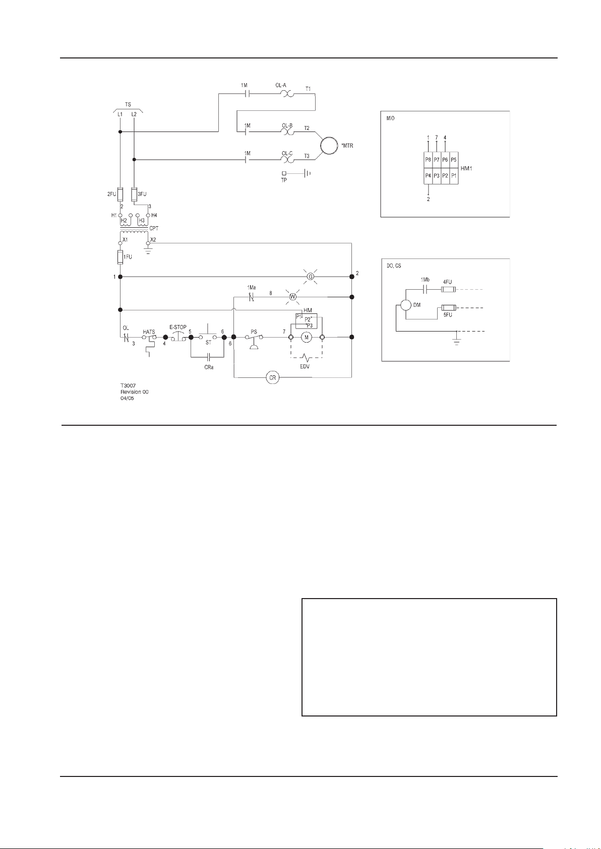
MANUEL D’UTILISATION ET D’ENTRETIEN INFORMACION GENERAL
ESQUEMA ELÉCTRICO UP6 5–15 HP VOLTAJE TOTAL (FV) MONOFÁSICO 60 Hz – EE.UU.
CLAVE
1FU,
2FU, 3FU
4FU, 5FU Fusible del secador MIO Indicador, mantenimiento opcional
1Ma Contacto del motor de arranque auxiliar (en lugar del contador horario estándar)
1Mb Contacto del motor de arranque auxiliar MTR Motor, compresor
CPT Transformador de control 120/1/50–60 OL Sobrecarga, arranque del motor
CR Relé de control TP Puntos terminales
CRa Contacto del relé de control TS Al suministro
CS Suministrado por el cliente 115 V/1 Ø/60 Hz W Luz de espera
DM Motor del secador
DO Opción de secador 1. (*) Suministrado, montado y cableado fuera del
EDV Válvula de drenaje eléctrica 2. El circuito se muestra en posición normal
E-STOP Botón, parada de emergencia 3. Deben marcarse todos los cables de acuerdo con
G Luz de encendido 4. Todos los cables deben estar en conformidad con el
HM Contador horario
HM1 Indicador, mantenimiento
Fusible del circuito de control M Motor de arranque de la bobina
Consultar la placa de identicación del
transformador para conocer los requisitos de
las conexiones del cableado. ST Botón de inicio
PS Interruptor de presión
NOTAS
panel de control, en caso necesario según el pedido.
desactivado.
este esquema.
NEC (código eléctrico nacional estadounidense).
http://air.ingersollrand.com 19
Page 68
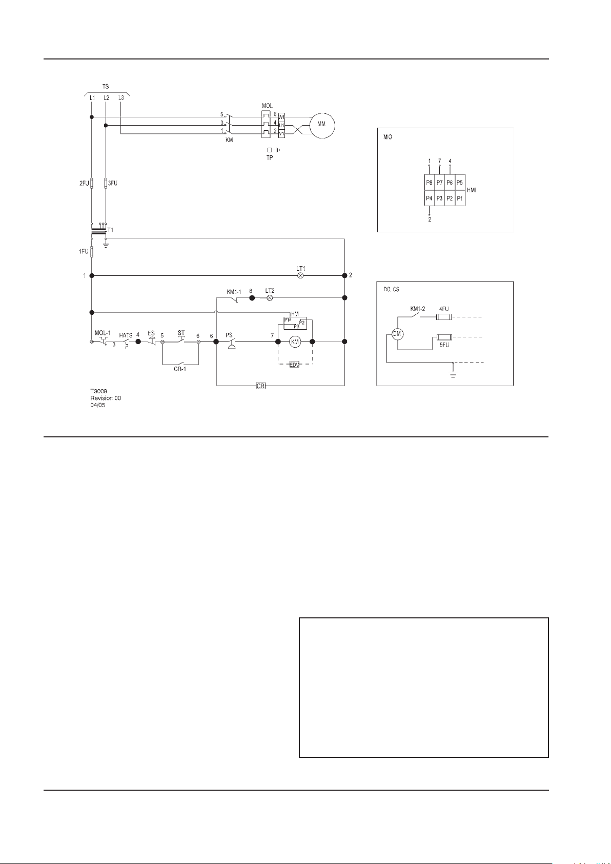
20 http://air.ingersollrand.com
INFORMACION GENERAL MANUEL D’UTILISATION ET D’ENTRETIEN
ESQUEMA ELÉCTRICO UP5 5–15 HP VOLTAJE TOTAL (FV) TRIFÁSICO 50 Hz ARRANQUE DIRECTO (DOL)
CLAVE
1FU Fusible secundario MIO Indicador, mantenimiento opcional (en lugar
del contador horario estándar)
2FU, 3FU Fusible primario MM Motor, compresor
4FU, 5FU Fusible del secador MOL Sobrecarga, motor principal
CR Relé de control MOL-1 Contacto, sobrecarga del motor principal
CS Suministrado por el cliente 230 V/1 Ø/50 Hz PS Interruptor de presión
DM Motor del secador ST Botón de inicio
DO Opción de secador T1 Transformador de control
EDV Válvula de drenaje eléctrica TP Puntos terminales
ES Botón, parada de emergencia TS Al suministro
HATS Interruptor, alta temperatura del aire
HM Contador horario
HM1 Indicador, mantenimiento
KM Contactor, principal 1.
KM–1,2 Contacto auxiliar. Contactor principal 2. El circuito se muestra en posición normal
LT1 Lámpara, indicadora de encendido (Verde) 3. Deben marcarse todos los cables de acuerdo
LT2 Lámpara, indicadora de rearranque
automático (Blanca)
NOTAS
(*) Suministrado, montado y cableado fuera del
panel de control, en caso necesario según el pedido.
desactivado.
con este esquema.
4. Todos los cables deben estar en conformidad
con el NEC (código eléctrico nacional
estadounidense).
Page 69
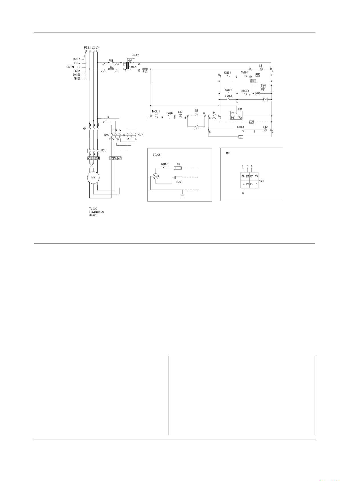
MANUEL D’UTILISATION ET D’ENTRETIEN INFORMACION GENERAL
ESQUEMA ELÉCTRICO UP5 5–15 HP VOLTAJE TOTAL (SD) TRIFÁSICO 50 Hz ARRANQUE DIRECTO
CLAVE
1SV Válvula de solenoide (NC) KM2-1,2 Contactos auxiliares. Contactor de triángulo
CR Relé de control KM3 Contactor de estrella
CR-1 Contacto del relé de control KM3-1,2 Contactos auxiliares. Contactor de estrella
CS
DM Motor del secador LT2
DO Opción de secador MIO Indicador, mantenimiento opcional
EDV Válvula de drenaje eléctrica (en lugar del contador horario estándar)
HATS Interruptor, alta temperatura del aire MOL Sobrecarga, motor principal
HM Contador horario MOL-1 Contacto, sobrecarga del motor principal
HM1 Indicador, mantenimiento ST Botón de inicio
MM Motor, compresor T1 Transformador de control
P Interruptor de presión TM1 Relé, arranque triángulo (10 segundos)
ES Botón, parada de emergencia TM1-1 Contacto de relé, retraso desconectado
FU1, FU2 Fusible primario
FU3 Fusible secundario
FU4, FU5 Fusible del secador 1. (*) Suministrado, montado y cableado fuera del
KM1 Contactor, principal 2. El circuito se muestra en posición normal
KM-1,2,3 Contacto auxiliar. Contactor principal 3. Deben marcarse todos los cables de acuerdo
KM2 Contactor de triángulo 4. Todos los cables deben estar en conformidad
Suministrado por el cliente 230 V/1 Ø/50 Hz
LT1 Lámpara, indicadora de encendido (Verde)
Lámpara, indicadora de rearranque automático
(Blanca)
NOTAS
panel de control, en caso necesario según el
pedido.
desactivado.
con este esquema.
con el NEC
(código eléctrico nacional estadounidense).
http://air.ingersollrand.com 21
Page 70
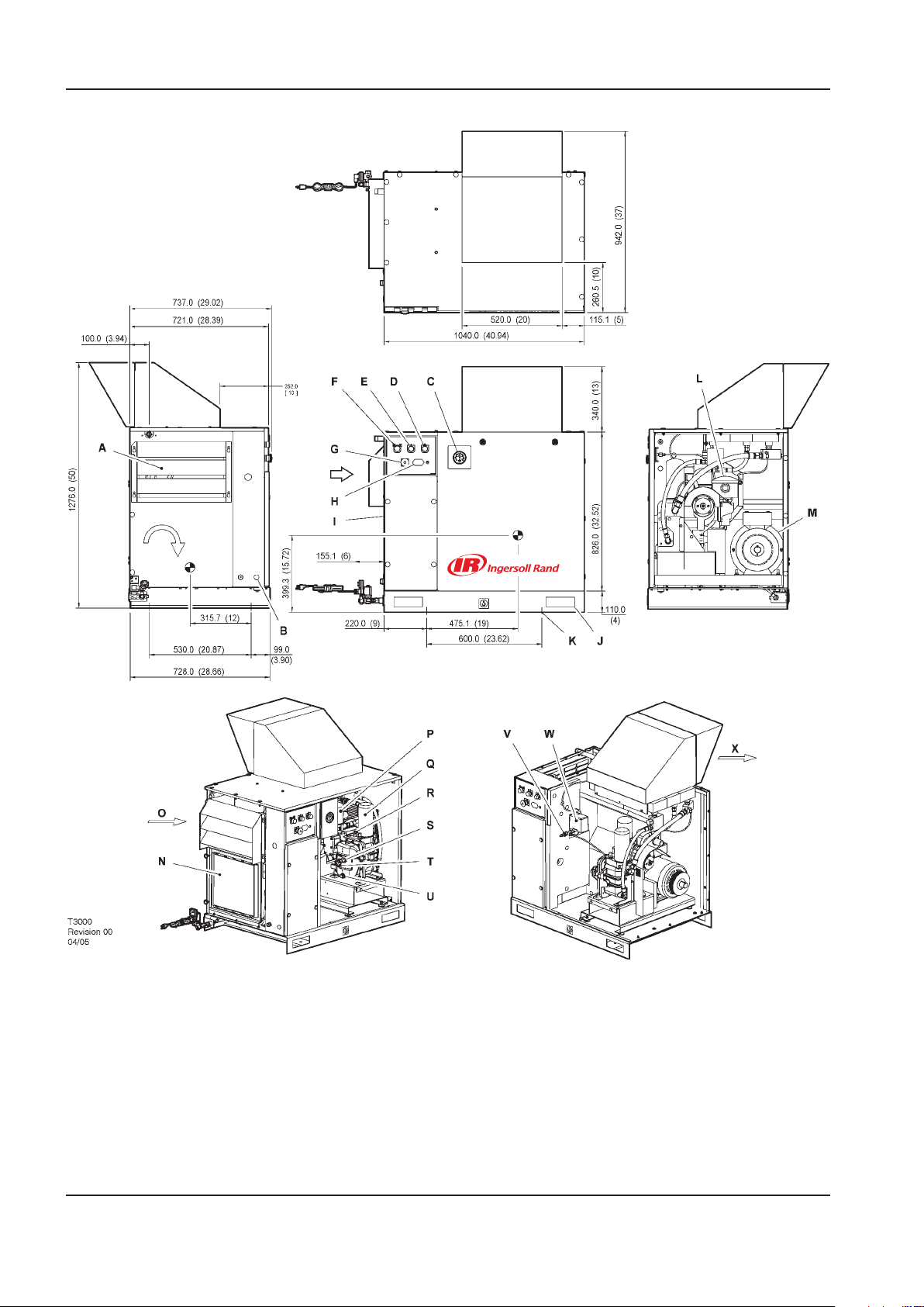
INSTALACIÓN / MANEJO MANUAL DE MANEJO Y MANTENIMIENTO
CON MOD. DE LA SERIE UP EXTERIORES OPCIONAL
CON MOD. DE LA SERIE UP EXTERIORES OPCIONAL
ROTACION
VISTA SUPERIOR
VISTA IZQUIERDA
VISTA DERECHA
VISTA FRONTAL
INSTALACIÓN / MANEJO
22 http://air.ingersollrand.com
Page 71

MANUAL DE MANEJO Y MANTENIMIENTO INSTALACIÓN / MANEJO
CLAVE
A Preltro del paquete M Motor
B Oricio, conducto del suministro de energía
entrante
C Manómetro O Compresor y admisión del aire refrigerante
D Luz amarilla de espera P Filtro del refrigerante
E Luz verde de encendido Q Cartucho del separador de líquido refrigerante
F Botón verde de inicio R Válvula de descarga de la unidad compresora
G Botón de parada de emergencia S Tapón de llenado de líquido refrigerante
H Contador horario T Mirilla
I Caja del arranque U Tapón de drenaje de líquido refrigerante
J Puntos de elevación V Válvula auxiliar
K Oricios de montaje (diámetro de 4 x 14,0 mm
[0,550 pulg.])
L Filtro de entrada de aire X Escape del aire refrigerante
NOTAS
1. La base o el suelo deberán estar nivelados y
soportar por igual todas las ubicaciones de los
pernos de montaje. De ser necesario, aplique
mortero o suplemento a la ubicación del cuarto
perno.
2. Los pernos de la base deberán sobresalir por las
tuercas un mínimo de 13 mm (0,50 pulg.) para
permitir el nivelado.
3. Se debe dejar un espacio libre mínimo de 1.100
mm (42 pulg.) en la parte frontal y de 920 mm (36
pulg.) en la parte superior, izquierda, derecha y
posterior del paquete, para una circulación de aire
y operabilidad apropiadas.
4. Peso aproximado del paquete: 298 kg (655 lb).
5. Las tuberías exteriores no han de ejercer
momentos o fuerzas no solucionados sobre la
unidad. Usar tubería tan grande o mayor en la
conexión de descarga.
6. Deberá prescindirse de montar tuberías de plástico
o de PVC en esta unidad o de usarles en conductos
cualesquiera aguas abajo.
7. No conectar a un tanque común con un compresor
de vaivén a menos que el compresor de vaivén
utilice un amortiguador de impulsos de descarga.
8. El tamaño de los componentes eléctricos
no suministrados por Ingersoll Rand es
responsabilidad del cliente y deberá decidirse de
conformidad con la información facilitada en
la chapa de datos del compresor, NEC y en los
códigos eléctricos a nivel nacional y local.
N Secador integrado (opcional)
W Presostato
NOTA
Todas las dimensiones se expresan en milímetros
(pulgadas) a menos que se indiquen de otro
modo.
Cerciorarse de que se usan las ranuras o los puntos
de elevación marcados de la carretilla elevadora que
sean los correctos siempre que se eleve o transporte la
máquina.
DESEMBALAJE
Normalmente el compresor se entrega con un
envoltorio de politeno. Si se ha de usar un cuchillo para
quitar este envoltorio tenga cuidado de no dañar la
pintura exterior del compresor.
Cerciorarse de que todos los materiales utilizados para
el transporte y embalaje se desechen de la manera
prescrita por los códigos locales.
http://air.ingersollrand.com 23
Page 72
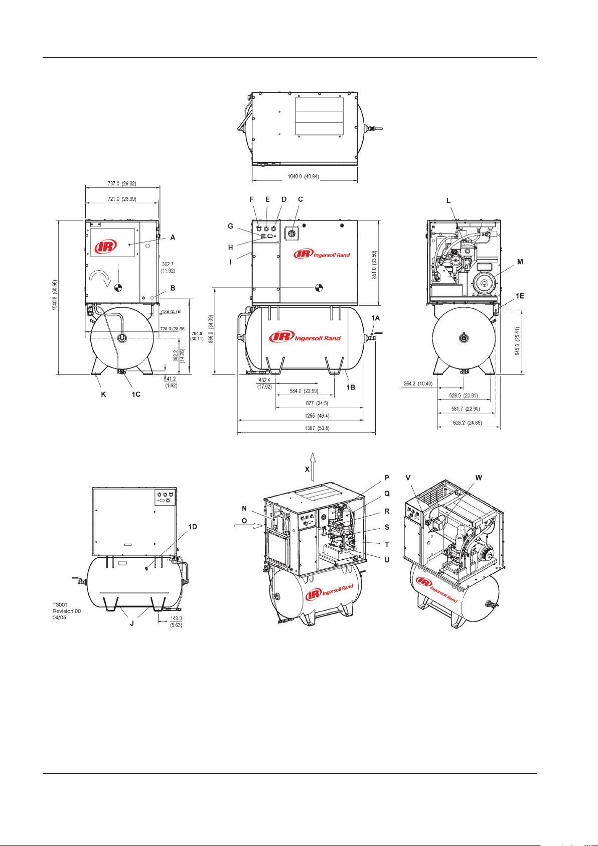
INSTALACIÓN / MANEJO MANUAL DE MANEJO Y MANTENIMIENTO
VISTA DERECHA
VISTA FRONTAL
VISTA IZQUIERDA
RO
T
AC
I
ON
VISTA SUPERIOR
CO
N
MO
D.
DE
L
A SER
IE UP EX
TERIORES
OPCIONAL
CO
N
MO
D.
DE
L
A SER
IE UP EX
TERIORES
OPCIONAL
CON MOD. DE LA SERIE UP EXTERIORES OPCIONAL
MONTAODS EN TANQUES (80 GALONES)
24 http://air.ingersollrand.com
Page 73

MANUAL DE MANEJO Y MANTENIMIENTO INSTALACIÓN / MANEJO
CLAVE
A Preltro del paquete P Filtro del refrigerante
B Oricio, conducto del suministro de energía
entrante
C Manómetro R Válvula de descarga de la unidad compresora
D Luz amarilla de espera S Tapón de llenado de líquido refrigerante
E Luz verde de encendido T Mirilla
F Botón verde de inicio U Tapón de drenaje de líquido refrigerante
G Botón de parada de emergencia V Válvula auxiliar
H Contador horario W Presostato
I Caja del arranque X Escape del aire refrigerante
J Puntos de elevación 1A Válvula esférica 0.75” N.P.T.
K Oricios de montaje (ranuras: 4 x 17,5 mm
[0,68 pulg.] x 44,5 mm [1,75 pulg.])
L Filtro de entrada de aire 1C Ubicación del drenaje manual del recipiente
M Motor 1D Válvula de descarga del depósito
N Secador integrado (opcional) 1E Puerto de descarga de 6,3 mm (0,25 pulg.) para una
O Compresor y admisión del aire refrigerante
Q Cartucho del separador de líquido refrigerante
1B Recipiente de almacenamiento del aire ( 620.0mm x
1168.4mm LG) ( 24.40” x 46.00” LG)
válvula de drenaje eléctrica opcional
NOTAS
1. La base o el suelo deberán estar nivelados y
soportar por igual todas las ubicaciones de los
pernos de montaje. De ser necesario, aplique
mortero o suplemento a la ubicación del cuarto
perno.
2. Los pernos de la base deberán sobresalir por las
tuercas un mínimo de 13 mm (0,50 pulg.) para
permitir el nivelado.
3. Se debe dejar un espacio libre mínimo de 1.100
mm (42 pulg.) en la parte frontal y de 920 mm (36
pulg.) en la parte superior, izquierda, derecha y
posterior del paquete, para una circulación de aire
y operabilidad apropiadas.
4. Peso aproximado del paquete: 298 kg (655 lb).
5. Las tuberías exteriores no han de ejercer
momentos o fuerzas no solucionados sobre la
unidad. Usar tubería tan grande o mayor en la
conexión de descarga.
6. Deberá prescindirse de montar tuberías de plástico
o de PVC en esta unidad o de usarles en conductos
cualesquiera aguas abajo.
7. No conectar a un tanque común con un compresor
de vaivén a menos que el compresor de vaivén
utilice un amortiguador de impulsos de descarga.
8. El tamaño de los componentes eléctricos
no suministrados por Ingersoll Rand es
responsabilidad del cliente y deberá decidirse de
conformidad con la información facilitada en
la chapa de datos del compresor, NEC y en los
códigos eléctricos a nivel nacional y local.
NOTA
Todas las dimensiones se expresan en milímetros
(pulgadas) a menos que se indiquen de otro
modo.
Cerciorarse de que se usan las ranuras o los puntos
de elevación marcados de la carretilla elevadora que
sean los correctos siempre que se eleve o transporte la
máquina.
DESEMBALAJE
Normalmente el compresor se entrega con un
envoltorio de politeno. Si se ha de usar un cuchillo para
quitar este envoltorio tenga cuidado de no dañar la
pintura exterior del compresor.
Cerciorarse de que todos los materiales utilizados para
el transporte y embalaje se desechen de la manera
prescrita por los códigos locales.
http://air.ingersollrand.com 25
Page 74
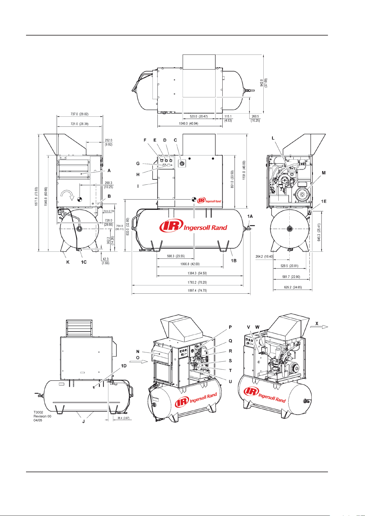
INSTALACIÓN / MANEJO MANUAL DE MANEJO Y MANTENIMIENTO
VISTA SUPERIOR
VISTA IZQUIERDA
VISTA FRONTAL
VISTA DERECHA
RO
T
AC
I
ON
CO
N
MO
D.
DE
L
A SERIE
UP EX
TERIORES
OP
CIONAL
CO
N
MO
D.
DE
L
A SER
IE UP
E
XTERIORES
OPCI
ON
A
L
MONTAODS EN TANQUES (120 GALONES)
26 http://air.ingersollrand.com
Page 75

MANUAL DE MANEJO Y MANTENIMIENTO INSTALACIÓN / MANEJO
CLAVE
A Preltro del paquete P Filtro del refrigerante
B Oricio, conducto del suministro de energía
entrante
C Manómetro R Válvula de descarga de la unidad compresora
D Luz amarilla de espera S Tapón de llenado de líquido refrigerante
E Luz verde de encendido T Mirilla
F Botón verde de inicio U Tapón de drenaje de líquido refrigerante
G Botón de parada de emergencia V Válvula auxiliar
H Contador horario W Presostato
I Caja del arranque X Escape del aire refrigerante
J Puntos de elevación 1A Válvula esférica 0.75” N.P.T.
K Oricios de montaje (ranuras: 4 x 17,5 mm [0,68
pulg.] x 44,5 mm [1,75 pulg.])
L Filtro de entrada de aire 1C Ubicación del drenaje manual del recipiente
M Motor 1D Válvula de descarga del depósito
N Secador integrado (opcional) 1E Puerto de descarga de 6,3 mm (0,25 pulg.) para una
O Compresor y admisión del aire refrigerante válvula de drenaje eléctrica opcional
Q Cartucho del separador de líquido refrigerante
1B Recipiente de almacenamiento del aire (Ø 618.0mm
x 1701.0mm LG) (Ø 24.33” x 67.00” LG)
NOTAS
1. La base o el suelo deberán estar nivelados y
soportar por igual todas las ubicaciones de los
pernos de montaje. De ser necesario, aplique
mortero o suplemento a la ubicación del cuarto
perno.
2. Los pernos de la base deberán sobresalir por las
tuercas un mínimo de 13 mm (0,50 pulg.) para
permitir el nivelado.
3. Se debe dejar un espacio libre mínimo de 1.100
mm (42 pulg.) en la parte frontal y de 920 mm (36
pulg.) en la parte superior, izquierda, derecha y
posterior del paquete, para una circulación de aire
y operabilidad apropiadas.
4. Peso aproximado del paquete: 298 kg (655 lb).
5. Las tuberías exteriores no han de ejercer
momentos o fuerzas no solucionados sobre la
unidad. Usar tubería tan grande o mayor en la
conexión de descarga.
6. Deberá prescindirse de montar tuberías de plástico
o de PVC en esta unidad o de usarles en conductos
cualesquiera aguas abajo.
7. No conectar a un tanque común con un compresor
de vaivén a menos que el compresor de vaivén
utilice un amortiguador de impulsos de descarga.
8. El tamaño de los componentes eléctricos
no suministrados por Ingersoll Rand es
responsabilidad del cliente y deberá decidirse de
conformidad con la información facilitada en
la chapa de datos del compresor, NEC y en los
códigos eléctricos a nivel nacional y local.
NOTA
Todas las dimensiones se expresan en milímetros
(pulgadas) a menos que se indiquen de otro
modo.
Cerciorarse de que se usan las ranuras o los puntos
de elevación marcados de la carretilla elevadora que
sean los correctos siempre que se eleve o transporte la
máquina.
DESEMBALAJE
Normalmente el compresor se entrega con un
envoltorio de politeno. Si se ha de usar un cuchillo para
quitar este envoltorio tenga cuidado de no dañar la
pintura exterior del compresor.
Cerciorarse de que todos los materiales utilizados para
el transporte y embalaje se desechen de la manera
prescrita por los códigos locales.
http://air.ingersollrand.com 27
Page 76
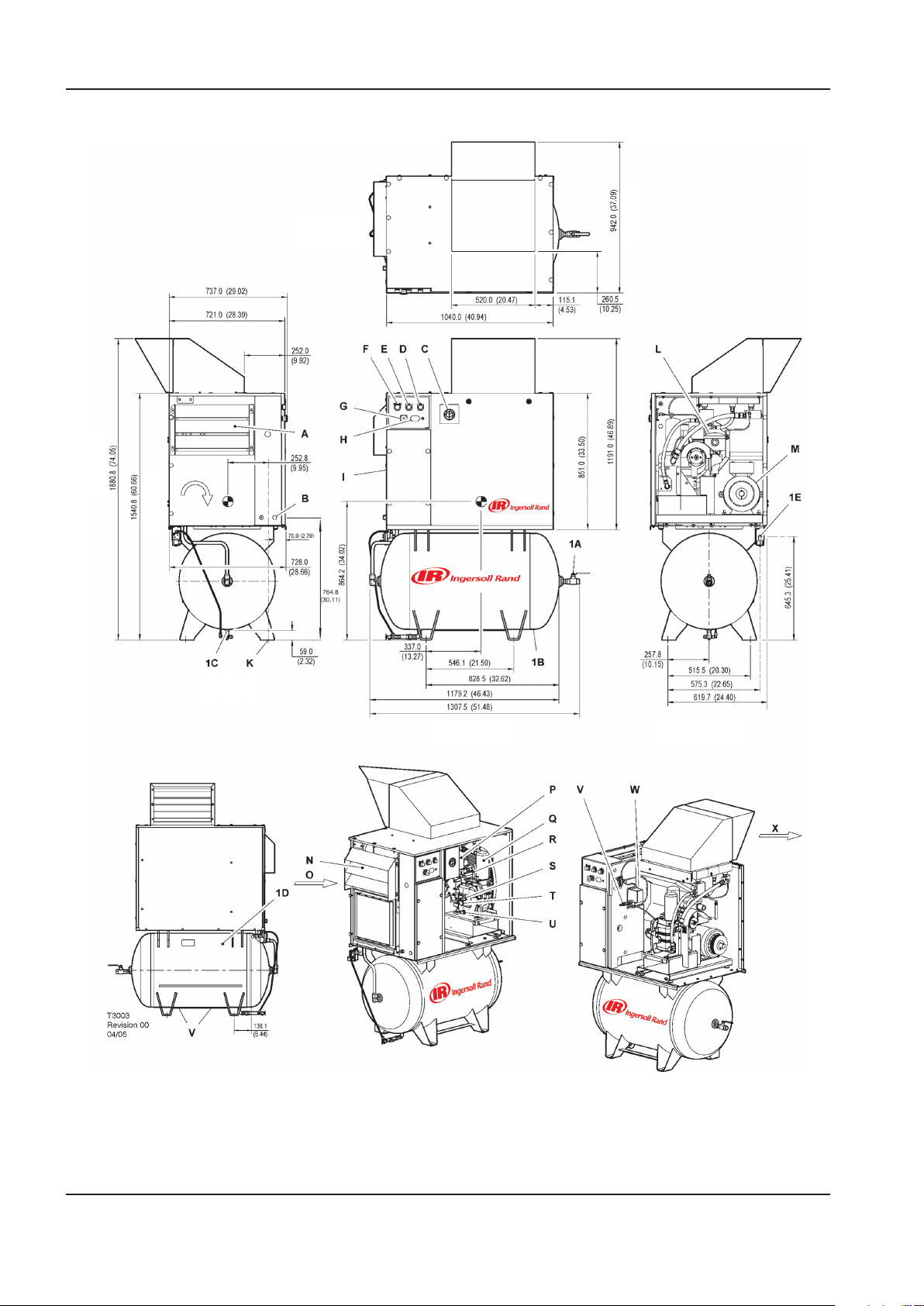
INSTALACIÓN / MANEJO MANUAL DE MANEJO Y MANTENIMIENTO
VISTA SUPERIOR
RO
T
AC
I
ON
VISTA IZQUIERDA
VISTA FRONTAL
VISTA DERECHA
CO
N
MO
D.
DE
L
A SER
IE UP EX
TE
R
IORES
OPCIONA
L
CO
N
MOD.
DE
L
A SER
IE UP EX
TERIORES OPCIONAL
MONTAODS EN TANQUES (272 LITRES)
28 http://air.ingersollrand.com
Page 77

MANUAL DE MANEJO Y MANTENIMIENTO INSTALACIÓN / MANEJO
CLAVE
A Preltro del paquete P Filtro del refrigerante
B Oricio, conducto del suministro de energía
entrante
C Manómetro R Válvula de descarga de la unidad compresora
D Luz amarilla de espera S Tapón de llenado de líquido refrigerante
E Luz verde de encendido T Mirilla
F Botón verde de inicio U Tapón de drenaje de líquido refrigerante
G Botón de parada de emergencia V Válvula auxiliar
H Contador horario W Presostato
I Caja del arranque X Escape del aire refrigerante
J Puntos de elevación 1A Válvula esférica 0.75” N.P.T.
K Oricios de montaje (ranuras: 4 x 17,5 mm [0,68
pulg.] x 44,5 mm [1,75 pulg.])
L Filtro de entrada de aire 1C Ubicación del drenaje manual del recipiente
M Motor 1D Válvula de descarga del depósito
N Secador integrado (opcional) 1E Puerto de descarga de 6,3 mm (0,25 pulg.) para una
O Compresor y admisión del aire refrigerante válvula de drenaje eléctrica opcional
Q Cartucho del separador de líquido refrigerante
1B Recipiente de almacenamiento del aire (Ø 600.0mm
x 1111.0mm LG) (Ø 23.62” x 43.74” LG)
NOTAS
1. La base o el suelo deberán estar nivelados y
soportar por igual todas las ubicaciones de los
pernos de montaje. De ser necesario, aplique
mortero o suplemento a la ubicación del cuarto
perno.
2. Los pernos de la base deberán sobresalir por las
tuercas un mínimo de 13 mm (0,50 pulg.) para
permitir el nivelado.
3. Se debe dejar un espacio libre mínimo de 1.100
mm (42 pulg.) en la parte frontal y de 920 mm (36
pulg.) en la parte superior, izquierda, derecha y
posterior del paquete, para una circulación de aire
y operabilidad apropiadas.
4. Peso aproximado del paquete: 298 kg (655 lb).
5. Las tuberías exteriores no han de ejercer
momentos o fuerzas no solucionados sobre la
unidad. Usar tubería tan grande o mayor en la
conexión de descarga.
6. Deberá prescindirse de montar tuberías de plástico
o de PVC en esta unidad o de usarles en conductos
cualesquiera aguas abajo.
7. No conectar a un tanque común con un compresor
de vaivén a menos que el compresor de vaivén
utilice un amortiguador de impulsos de descarga.
8. El tamaño de los componentes eléctricos
no suministrados por Ingersoll Rand es
responsabilidad del cliente y deberá decidirse de
conformidad con la información facilitada en
la chapa de datos del compresor, NEC y en los
códigos eléctricos a nivel nacional y local.
NOTA
Todas las dimensiones se expresan en milímetros
(pulgadas) a menos que se indiquen de otro
modo.
Cerciorarse de que se usan las ranuras o los puntos
de elevación marcados de la carretilla elevadora que
sean los correctos siempre que se eleve o transporte la
máquina.
DESEMBALAJE
Normalmente el compresor se entrega con un
envoltorio de politeno. Si se ha de usar un cuchillo para
quitar este envoltorio tenga cuidado de no dañar la
pintura exterior del compresor.
Cerciorarse de que todos los materiales utilizados para
el transporte y embalaje se desechen de la manera
prescrita por los códigos locales.
http://air.ingersollrand.com 29
Page 78
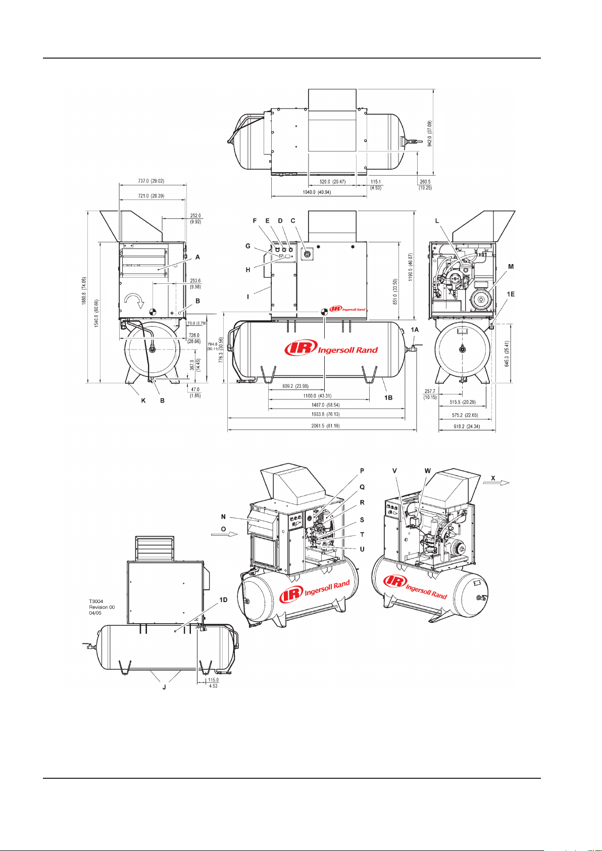
INSTALACIÓN / MANEJO MANUAL DE MANEJO Y MANTENIMIENTO
VISTA DERECHA
VISTA FRONTAL
VISTA IZQUIERDA
RO
T
AC
I
ON
VISTA SUPERIOR
CO
N
MO
D.
DE LA SER
IE
UP EX
TERIORES
OPCIONAL
CO
N
MO
D.
DE
L
A SER
IE UP EX
TERIORES
OPCIONAL
MONTAODS EN TANQUES (500 LITRES)
30 http://air.ingersollrand.com
Page 79

MANUAL DE MANEJO Y MANTENIMIENTO INSTALACIÓN / MANEJO
CLAVE
A Preltro del paquete P Filtro del refrigerante
B Oricio, conducto del suministro de energía
entrante
C Manómetro R Válvula de descarga de la unidad compresora
D Luz amarilla de espera S Tapón de llenado de líquido refrigerante
E Luz verde de encendido T Mirilla
F Botón verde de inicio U Tapón de drenaje de líquido refrigerante
G Botón de parada de emergencia V Válvula auxiliar
H Contador horario W Presostato
I Caja del arranque X Escape del aire refrigerante
J Puntos de elevación 1A Válvula esférica 0.75” N.P.T.
K Oricios de montaje (ranuras: 4 x 17,5 mm [0,68
pulg.] x 44,5 mm [1,75 pulg.])
L Filtro de entrada de aire 1C Ubicación del drenaje manual del recipiente
M Motor 1D Válvula de descarga del depósito
N Secador integrado (opcional) 1E Puerto de descarga de 6,3 mm (0,25 pulg.) para una
O Compresor y admisión del aire refrigerante válvula de drenaje eléctrica opcional
Q Cartucho del separador de líquido refrigerante
1B Recipiente de almacenamiento del aire (Ø610.0mm
x 1866.0mm LG) (Ø24.02” x 73.46” LG)
NOTAS
1. La base o el suelo deberán estar nivelados y
soportar por igual todas las ubicaciones de los
pernos de montaje. De ser necesario, aplique
mortero o suplemento a la ubicación del cuarto
perno.
2. Los pernos de la base deberán sobresalir por las
tuercas un mínimo de 13 mm (0,50 pulg.) para
permitir el nivelado.
3. Se debe dejar un espacio libre mínimo de 1.100
mm (42 pulg.) en la parte frontal y de 920 mm (36
pulg.) en la parte superior, izquierda, derecha y
posterior del paquete, para una circulación de aire
y operabilidad apropiadas.
4. Peso aproximado del paquete: 298 kg (655 lb).
5. Las tuberías exteriores no han de ejercer
momentos o fuerzas no solucionados sobre la
unidad. Usar tubería tan grande o mayor en la
conexión de descarga.
6. Deberá prescindirse de montar tuberías de plástico
o de PVC en esta unidad o de usarles en conductos
cualesquiera aguas abajo.
7. No conectar a un tanque común con un compresor
de vaivén a menos que el compresor de vaivén
utilice un amortiguador de impulsos de descarga.
8. El tamaño de los componentes eléctricos
no suministrados por Ingersoll Rand es
responsabilidad del cliente y deberá decidirse de
conformidad con la información facilitada en
la chapa de datos del compresor, NEC y en los
códigos eléctricos a nivel nacional y local.
NOTA
Todas las dimensiones se expresan en milímetros
(pulgadas) a menos que se indiquen de otro
modo.
Cerciorarse de que se usan las ranuras o los puntos
de elevación marcados de la carretilla elevadora que
sean los correctos siempre que se eleve o transporte la
máquina.
DESEMBALAJE
Normalmente el compresor se entrega con un
envoltorio de politeno. Si se ha de usar un cuchillo para
quitar este envoltorio tenga cuidado de no dañar la
pintura exterior del compresor.
Cerciorarse de que todos los materiales utilizados para
el transporte y embalaje se desechen de la manera
prescrita por los códigos locales.
http://air.ingersollrand.com 31
Page 80
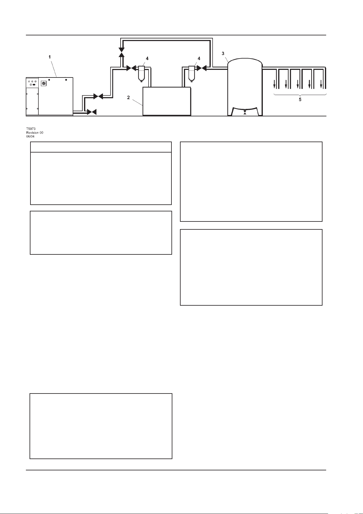
INSTALACIÓN / MANEJO MANUAL DE MANEJO Y MANTENIMIENTO
CLAVE
Compresor
1.
Secador de aire
2.
Colector de aire
3.
Filtros de aire comprimido
4.
Puntos de demanda del sistema
5.
AVISO
Los elementos [2] a [5] son opcionales o pueden
ser elementos existentes de la planta. Dirigirse
a su distribuidor o representante de Ingersoll
Rand para recomendaciones especícas.
UBICACION EN LA PLANTA
El compresor se puede instalar sobre cualquier suelo
nivelado capaz de soportarlo. Se recomienda que la
zona sea seca y bien ventilada en la que el ambiente
sea lo más limpio posible. Deberá dejarse un mínimo de
150mm (6 pulgadas) en la parte posterior y 1 m (3 pies)
en los costados de la máquina para tener un acceso para
servicio y una ventilación adecuados.
Hay que tener adecuado lugar libre alrededor de la
máquina para hacer sin estorbo las tareas indicadas de
mantenimiento.
Cerciórese de situar la máquina con seguridad sobre
una supercie rme. Elimínese por medios apropiados
cualquier posibilidad de que la máquina se mueva,
especialmente para que no se esfuerce ninguna tubería
rígida de descarga.
PRECAUCION
Los compresores [1] tipo tornillo no deben
instalarse en sistemas de aire con compresores
alternativos sin medios de independización, tal
como un tanque colector común. Se recomienda
que ambos tipos de compresor se conecten a
un colector común utilizando tuberías de aire
independientes..
PRECAUCION
El empleo de recipientes de plástico en ltros
de conductos o en otros componentes de los
conductos de aire de plástico puede resultar
peligroso. Su seguridad puede verse afectada
bien sea por refrigerantes sintéticos o por
aditivos utilizados en aceites minerales.
Ingersoll Rand recomienda utilizar sólo
recipientes de metal en sistemas sometidos a
presión.
PRECAUCION
La unidad de compresor estándar no resulta
idónea para operar bajo temperaturas que
puedan ocasionar congelación ya que es
propenso a producirse agua de condensado en
el post–refrigerador y en el colector si se han
instalado.
Para mayor información, consultar al
distribuidor de Ingersoll Rand.
TUBERIA DE DESCARGA
La tubería de descarga debe ser por lo menos de igual
diámetro que la conexión de la descarga del compresor.
Todas las tuberías y accesorios deben tener unas
características nominales adecuabas a la presión de
descarga.
Es esencial cuando se instala un nuevo compresor
[1], revisar el sistema de aire completo. Esto sirve para
conseguir un sistema seguro y efectivo. Un punto que
debe ser tenido en cuenta es el arrastre de líquido. La
instalación de secadores de aire [3], es siempre una buena
práctica ya que seleccionados e instalados correctamente
pueden reducir el arrastre de líquido a cero.
Es una buena práctica colocar una válvula de
aislamiento cerca del compresor e instalar ltros en la
tubería [4].
Tratándose de secadores de aire cubiertos por AirCare,
es un requisito instalar ltros previos y posteriores de
Ingersoll Rand de medidas correctas.
32 http://air.ingersollrand.com
Page 81
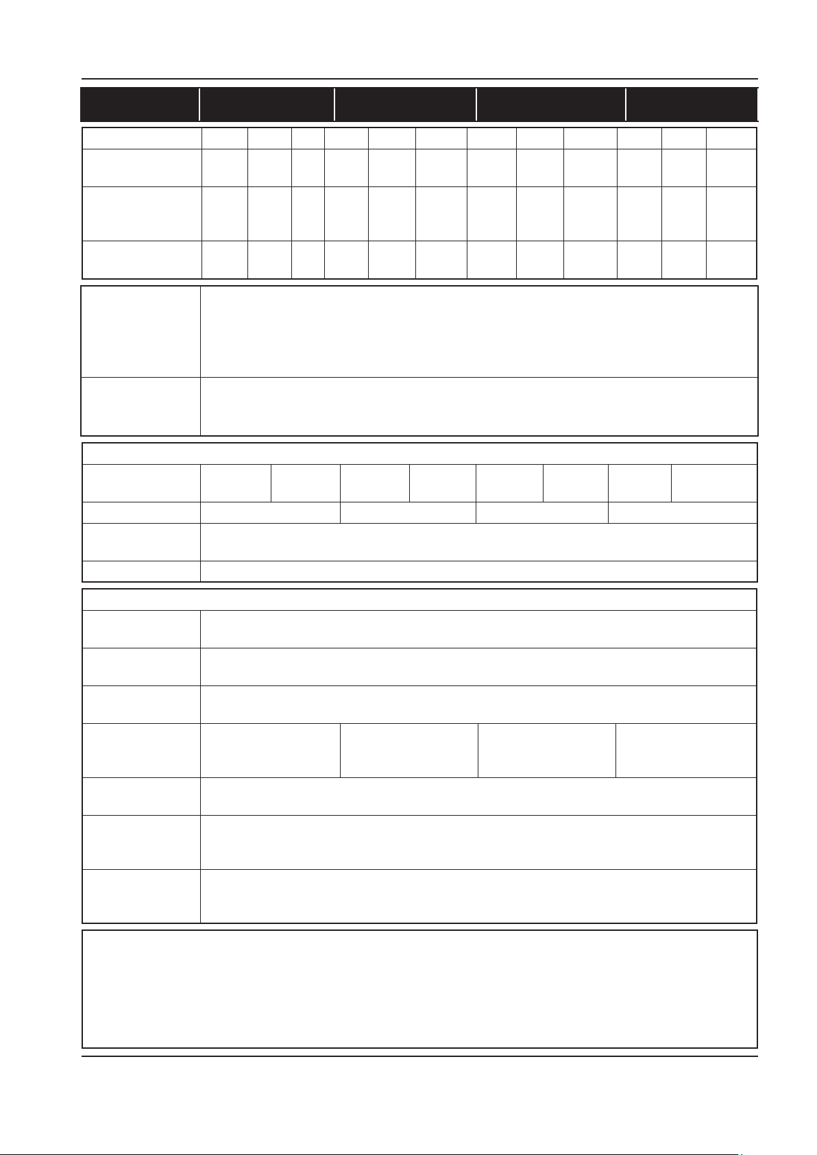
MANUAL DE MANEJO Y MANTENIMIENTO INSTALACIÓN / MANEJO
60Hz UP6 5 UP6 7 UP6 10 UP6 15c
COMPRESOR 125 150 210 125 150 210 125 150 210 125 150 210
Presión de trabajo
PSIG (bar)
Presión de recarga
jada en fábrica
PSIG (bar)
Medida del gasto
CFM (m3/MIN)
Punto de disparo
de la temperatura
de descarga
de la unidad
compresora
Temperatura
ambiente
(mín. → (máx.)
MOTOR
Envolvente del
motor
Potencia nominal 5HP 7.5HP 10HP 15HP
Número de revolu-
ciones
Arrollamiento F F
DATOS GENERALES
Contenido restante de aceite
Capacidad del
depósito de aceite
Carga de aceite
total
Nivel de emisión
según CAGI–Pneurop
Peso – Unidad con
base montada
Peso – Unidad de
80 galones con
depósito montado
Peso – Unidad de
120 galones con
depósito montado
PRECAUCION
Las máquinas de doble tensión 230/460 están dotadas de una calcomanía para indicar la tensión correcta que se
ha conectado en fábrica.
La puerta del arranque lleva montada una calcomanía que describe el procedimiento para cambiar los conectores
para la tensión alternativa.
El recableado sólo deberá realizarlo un electricista competente.
125
(8.6)
110
(7.58)
18.5
(0.52)
150
(10.3)
130
(8.96)
16.0
(0.45)
-- 125
(8.6)
-- 110
(7.58)
-- 28.0
(0.79)
150
(10.3)
130
(8.96)
25.0
(0.71)
210
(14.5)
180
(12.41)
17.5
(0.50)
125
(8.6)
110
(7.58)
38.0
(1.08)
150
(10.3)
130
(8.96)
34
(0.96)
210
(14.5)
180
(12.41)
24.0
(0.68)
125
(8.6)
110
(7.58)
55.0
(1.55)
150
(10.3)
130
(8.96)
50.0
(1.42)
228°F (109°C)
36°F (+2°C) → 105°F (+40°C)
ODP TEFC ODP TEFC ODP TEFC ODP TEFC
3500 RPM
3ppm (3 mg/m3)
0.8 gallons (3 Litres)
1.2 gallons (4.5 Litres)
65 dB(A) 65 dB(A) 68 dB(A) 69 dB(A)
295kg (650lb)
420kg (925lb)
436kg (960lb)
210
(14.5)
180
(12.41)
38.0
(1.08)
http://air.ingersollrand.com 33
Page 82
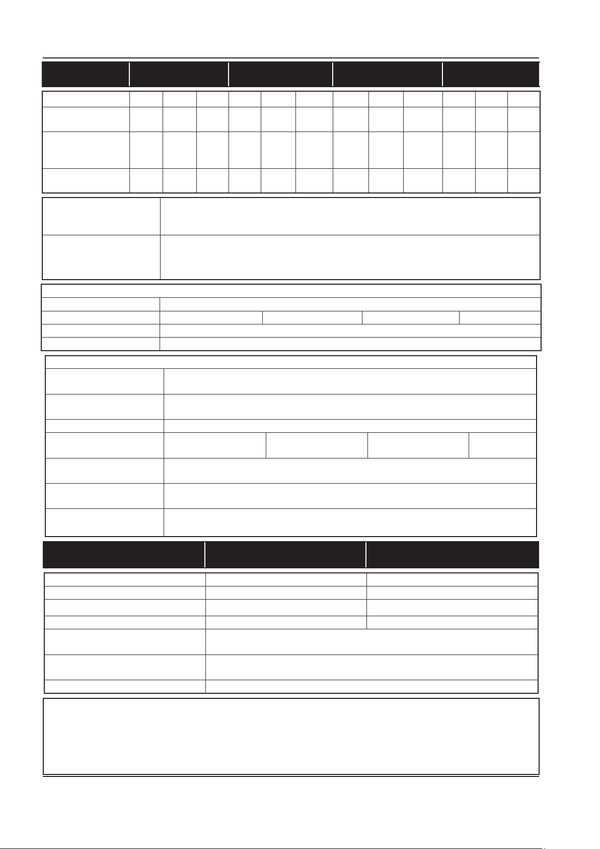
INSTALACIÓN / MANEJO MANUAL DE MANEJO Y MANTENIMIENTO
50Hz UP5 4 UP5 5 UP5 7 UP5 11c
COMPRESOR 8 10 14.5 8 10 14.5 8 10 14.5 8 10 14.5
Presión de trabajo
PSIG (bar)
Presión de recarga
jada en fábrica
PSIG (bar)
Medida del gasto
CFM (m3/MIN)
Punto de disparo de la
temperatura de descarga
de la unidad compresora
115
(8)
100
(7.58)
19.5
(0.55)
145
(10)
125
(8.96)
16.0
(0.45)
210
(14.5)
-- 100
-- 29.0
115
(8)
(7.93)
(0.82)
145
(10)
125
(9.66)
26.0
(0.74)
210
(14.5)
180
(13.10)
18.0
(0.51)
228°F (109°C)
115
(8)
100
(7.93)
38.0
(1.08)
145
(10)
125
(9.66)
34
(0.96)
210
(14.5)
180
(13.10)
24.0
(0.68)
115
(8)
100
(7.93)
56.5
(1.60)
145
(10)
125
(9.66)
50.0
(1.92)
210
(14.5)
180
(13.1)
38.0
(8.6)
Temperatura ambiente
(mín. → (máx.)
36°F (+2°C) → 105°F (+40°C)
MOTOR
Envolvente del motor TEFC
Potencia nominal 4KW 5.5KW 7.5KW 11KW
Número de revoluciones 2900 RPM
Arrollamiento F F
DATOS GENERALES
Contenido restante de
3ppm (3 mg/m3)
aceite
Capacidad del depósito de
0.8 gallons (3 Litres)
aceite
Carga de aceite total 1.2 gallons (4.5 Litres)
Nivel de emisión según
65 dB(A) 65 dB(A) 68 dB(A) 69 dB(A)
CAGI–Pneurop
Peso – Unidad con base
295kg (650lb)
montada
Peso – 272 litros con
420kg (925lb)
depósito montado
Peso – 500 litros con
454kg (1000lb)
depósito montado
DATOS TÉCNICOS DEL
60Hz 50Hz
SECADOR
Suministro eléctrico 115V - 1ph - 60Hz 230V - 1ph - 50Hz
Corriente con el rotor bloqueado (A) 30.0 12.6
Corriente a plena carga (A) 5.0 2.7
Total installed power (kW) 0.46 0.47
Energía total instalada (kW) NEMA 1
(IP 20)
Clase de protección eléctrica (std) 0.78 lb
354 g
Tipo de refrigeración 134 A
PRECAUCION
Las máquinas de doble tensión 230/460 están dotadas de una calcomanía para indicar la tensión correcta que se
ha conectado en fábrica.
La puerta del arranque lleva montada una calcomanía que describe el procedimiento para cambiar los conectores
para la tensión alternativa.
El recableado sólo deberá realizarlo un electricista competente.
34 http://air.ingersollrand.com
Page 83
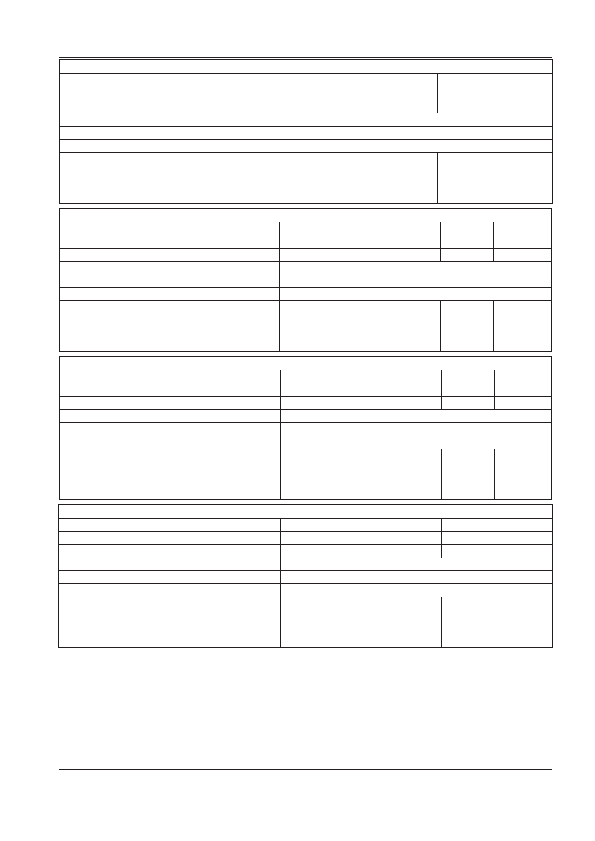
MANUAL DE MANEJO Y MANTENIMIENTO INSTALACIÓN / MANEJO
DATOS ELÉCTRICOS – UP6 5
Tensión estándar 230V/1PH 200V 230V/3PH 460V 575V
Corriente a plena carga (máxima) 23.5A 15.5A 13.5A 6.8A 5.4A
Corriente de arranque directo DOL (estrella triángulo)
Tiempo de arranque directo DOL (estrella triángulo)
Arranques por hora (máximos) 6
Tensión de control 120VAC
Capacidad recomendada de los fusibles. Consultar
la nota 1.
Medida recomendada de los cables AWG. Consul-
tar la nota 2.
DATOS ELÉCTRICOS – UP6 7.5
Tensión estándar 230V/1PH 200V 230V/3PH 460V 575V
Corriente a plena carga (máxima) 34.1A 22.7A 19.7A 9.9A 7.9A
Corriente de arranque directo DOL (estrella triángulo)
Tiempo de arranque directo DOL (estrella triángulo)
Arranques por hora (máximos) 6
Tensión de control 120VAC
Capacidad recomendada de los fusibles. Consultar
la nota 1.
Medida recomendada de los cables AWG. Consultar
la nota 2.
DATOS ELÉCTRICOS – UP6 10
Tensión estándar 230V/1PH 200V 230V/3PH 460V 575V
Corriente a plena carga (máxima) - 29.8A 26.0A 13.0A 10.3A
Corriente de arranque directo DOL (estrella triángulo)
Tiempo de arranque directo DOL (estrella triángulo) 3–5 Sec (7–10 Sec)
Arranques por hora (máximos) 6
Tensión de control 120VAC
Capacidad recomendada de los fusibles. Consultar
la nota 1.
Medida recomendada de los cables AWG. Consultar
la nota 2.
DATOS ELÉCTRICOS – UP6 15c
Tensión estándar 230V/1PH 200V 230V/3PH 460V 575V
Corriente a plena carga (máxima) - 43.2A 37.6A 18.8A 15.1A
Corriente de arranque directo DOL (estrella triángulo)
Tiempo de arranque directo DOL (estrella triángulo) 3–5 Sec (7–10 Sec)
Arranques por hora (máximos) 6
Tensión de control 120VAC
Capacidad recomendada de los fusibles. Consultar
la nota 1.
Medida recomendada de los cables AWG. Consultar
la nota 2.
1. Si se selecciona un disyuntor, éste deberá ser de
tipo de disparo magnético, regulado por encima de la
corriente de arranque prevista de la máquina, si bien
por debajo de la corriente máxima de fallo posible. El
disyuntor o la desconexión de fusible ha de ser capaz
de interrumpir la corriente de fallo posible en sus
terminales.
2.
Tipo PVC/PVC Calculado usando las siguientes condiciones:
Cable aislado de PVC, blindado, conductores de cobre.
i)
- - - - 3–5 Sec (7–10 Sec)
40A 25A 20A 10A 8A
8 10 12 14 14
- - - - 3–5 Sec (7–10 Sec)
50A 35A 35A 15A 12A
6 8 10 14 14
- - - - -
- 50A 45A 20A 15A
- 8 8 12 14
- - - - -
- 75A 65A 30A 25A
- 4 6 10 10
Cable grapado a una pared, al aire libre.
ii)
Temperatura ambiente de 40°C (104°F) y
iii)
humedad relativa de 40%.
Recorrido de cable de 20m (65ft).
iv)
Caída de tensión limitada a –10% durante el
v)
arranque, –4% durante el funcionamiento normal.
Protegido por el interruptor de circuitos arriba
vi)
indicado.
http://air.ingersollrand.com 35
Page 84
INSTALACIÓN / MANEJO MANUAL DE MANEJO Y MANTENIMIENTO
DATOS ELÉCTRICOS – UP5 4
Tensión estándar 380V 400V
Corriente a plena carga (máxima) 8.9A 8.9A
Corriente de arranque directo DOL (estrella triángulo)
Tiempo de arranque directo DOL (estrella triángulo) 3–5 seg. (7–10 seg.)
Arranques por hora (máximos) 6
Tensión de control 120VAC
Capacidad recomendada de los fusibles. Consultar la
nota 1.
Medida recomendada de los cables. Consultar la
nota 2.
DATOS ELÉCTRICOS – UP5 5.5
Tensión estándar 380V 400V
Corriente a plena carga (máxima) 11.8A 11.2A
Corriente de arranque directo DOL (estrella triángulo) 100 95
Tiempo de arranque directo DOL (estrella triángulo) 3–5 seg. (7–10 seg.)
Arranques por hora (máximos) 6
Tensión de control 120VAC
Capacidad recomendada de los fusibles. Consultar la
nota 1.
Medida recomendada de los cables. Consultar la nota 2.
66 63
16A 16A
4 mm2Cu 4 mm2 Cu
16A 16A
4 mm2Cu 4 mm2 Cu
DATOS ELÉCTRICOS – UP5 7.5
Tensión estándar 380V 400V
Corriente a plena carga (máxima) 16.9A 15.6A
Corriente de arranque directo DOL (estrella triángulo) 121 (94) 114 (52)
Tiempo de arranque directo DOL (estrella triángulo) 3–5 seg. (7–10 seg.)
Arranques por hora (máximos) 6
Tensión de control 120VAC
Capacidad recomendada de los fusibles. Consultar la
20A 20A
nota 1.
Medida recomendada de los cables. Consultar la nota 2.
4 mm2 Cu 4 mm2 Cu
DATOS ELÉCTRICOS – UP5 11c
Tensión estándar 380V 400V
Corriente a plena carga (máxima) 23.0A 21.9A
Corriente de arranque directo DOL (estrella triángulo) (79) (75)
Tiempo de arranque directo DOL (estrella triángulo) 3–5 Sec (7–10 Sec)
Arranques por hora (máximos) 6
Tensión de control 120VAC
Capacidad recomendada de los fusibles. Consultar la
nota 1.
Medida recomendada de los cables. Consultar la nota 2.
1. Si se selecciona un disyuntor, éste deberá ser de
tipo de disparo magnético, regulado por encima de la
corriente de arranque prevista de la máquina, si bien
por debajo de la corriente máxima de fallo posible. El
disyuntor o la desconexión de fusible ha de ser capaz
de interrumpir la corriente de fallo posible en sus
terminales.
2. Tipo PVC/PVC Calculado usando las siguientes
condiciones:
C
able aislado de PVC, blindado, conductores de
i)
cobre.
32A 32A
6 mm2Cu 6 mm2 Cu
Cable grapado a una pared, al aire libre.
ii)
Temperatura ambiente de 40°C (104°F) y
iii)
humedad relativa de 40%.
Caída de tensión limitada a –10% durante el
iv)
arranque, –4% durante el funcionamiento norma
Protegido por el interruptor de circuitos arriba
v)
indicado.
l.
36 http://air.ingersollrand.com
Page 85

MANUAL DE MANEJO Y MANTENIMIENTO INSTALACIÓN / MANEJO
Si se produce alguna variación con respecto a lo
anterior, o son aplicables normas especiales, la
instalación ha de planicarla un técnico competente y
cualicado.
AVISO
¡Los datos técnicos son válidos exclusivamente
para la versión estándar!
CARACTERISTICAS ELECTRICAS
Deberá instalarse junto al compresor un aislador o
desconectador eléctrico independiente.
Los cables/hilos alimentadores deberán ser
dimensionados por el cliente/contratista electricista
para asegurarse de que los circuitos sean equilibrados
y no sobrecargados por otros equipos eléctricos. La
longitud del cableado desde un punto adecuado de
alimentación eléctrica resulta crítica dado que las
caídas de tensión pueden perjudicar el rendimiento del
compresor.
Las conexiones de los cables/hilos alimentadores al
aislador o desconectador deberán estar bien apretadas
y limpias.
La tensión de alimentación debe estar en consonancia
con los valores nominales de la placa de características
del motor y el compresor.
El transformador del circuito de control tiene diferentes
tomas de tensión. Asegurar que está ajustado a la
tensión especíca aplicada antes del arranque.
PRECAUCION
Nunca comprobar la resistencia de aislamiento
de cualquier parte de los circuitos de las
máquinas, el motor incluido, sin desconectar
por completo el controlador electrónico (si se ha
instalado).
ATENCIÓN
Asegurarse de que el motor gira en el sentido
correcto, tal y como indican las echas del
sentido de rotación.
http://air.ingersollrand.com 37
Page 86

INSTRUCCIONES DE OPERACION MANUAL DE MANEJO Y MANTENIMIENTO
INSTRUCCIONES DE OPERACION
FUNCIONAMIENTO GENERAL TION
El compresor es un equipo conducido por un motor
eléctrico, de simple etapa, de tipo tornillo, completo
con accesorios para tuberías, cableado y montado sobre
una placa base. Es un conjunto de compresión de aire
totalmente equipado.
El compresor estándar se ha diseñado para funcionar en
una gama de temperaturas ambiente de 2°C a 40°C (de
35,6°F a 104°F). La temperatura máxima es aplicable a
cualquiera de las versiones hasta una altitud máxima de
1.000 m (3.289 pies) sobre el nivel del mar. Por encima
de esta altitud, se requieren reducciones importantes de
las temperaturas ambiente.
La compresión en un compresor de aire tipo tornillo está
creada por el entrelazado de dos rotores helicoidales
(Macho y Hembra).
La mezcla de aire y refrigerante, descarga del compresor
en el sistema de separación. El sistema extrae todo
el refrigerante, excepto unas pocas PPM, del aire
de descarga. El refrigerante se devuelve al sistema
refrigerante y el aire pasa a través del postrefrigerador y
fuera del compresor.
El aire refrigerante es desplazado por los refrigeradores
mediante el ventilador de refrigeración y se descarga de
la máquina.
PRECAUCION
El aire refrigerante se hace entrar por el extremo
del paquete de la máquina y pasa después a
través del ltro y del refrigerador antes de ser
descargado por la parte superior de la máquina.
Deberá tenerse el cuidado de no obturar el ujo
del aire o de causar cualquier restricción que
supere la contrapresión máxima permitida para
su conducción.
No dirigir el ujo de aire hacia la cara o hacia los
ojos.
Enfriando el aire de descarga, se condensa una buena
parte del vapor de agua contenido de una forma natural
en el aire, pudiendose drenar las tuberías y equipos
corriente abajo.
asignada y está provisto de un sistema de auto arranque
para su utilización en plantas en las que hay una gran
variación en el consumo de aire.
Cuando el compresor se encuentra equipado con el
secador opcional, el secador funcionará durante los
ciclos con el compresor.
ADVERTENCIA
Cuando la unidad cese de funcionar como
consecuencia de la baja demanda de aire, lo
cual se indica normalmente mediante la luz
de rearranque automático, puede arrancar de
nuevo y volver a carga en cualquier momento.
Se provee seguridad de funcionamiento ya que el
compresor se parará si se experimentan condiciones de
excesivas temperaturas o de sobrecargas eléctricas.
PRECAUCION
Esta unidad no se ha diseñado ni propuesto
para funcionar cuando esté contaminada
de silicona. Los lubricantes, grasas y otros
productos que contengan silicona no deberán
utilizarse con esta unidad.
PRECAUCION
APLICACIONES DE BAJA DEMANDA
Durante los periodos de baja demanda, el
compresor puede no alcanzar su normal
temperatura de funcionamiento. El
funcionamiento sostenido a baja demanda
puede tener como resultado la acumulación
de condensación en el refrigerante. Si ocurre
esta situación, las características de lubricación
del refrigerante puede deteriorarse que puede
llevar a daños en el compresor.
AL COMPRESOR DEBE PERMITÍRSELE UN
AMPLIO TIEMPO DE FUNCIONAMIENTO DE AL
MENOS 10 MINUTOS POR HORA DURANTE EL
USO NORMAL DIARIO.
El sistema de refrigeración consta de un cárter, un
enfriador, una válvula thermostatic y un ltro. Cuando
el equipo está en funcionamiento, el refrigerante es
presurizado y forzado hacia los cojinetes del compresor.
El sistema de control de carga del compresor es
automático en servicio–fuera de servicio. El compresor
funcionará para mantener la presión de descarga
38 http://air.ingersollrand.com
Page 87
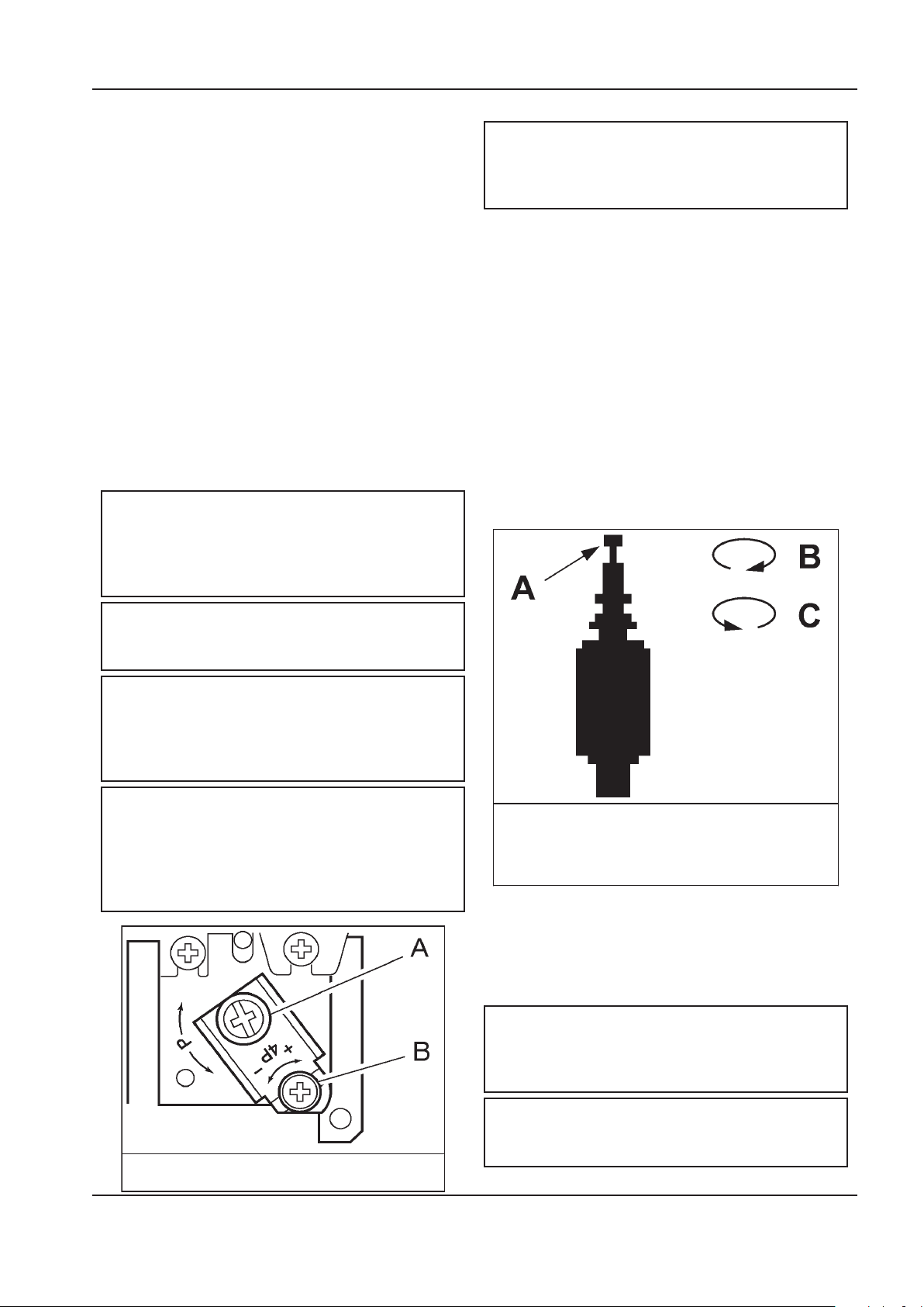
MANUAL DE MANEJO Y MANTENIMIENTO INSTRUCCIONES DE OPERACION
A. Ajuste de la presión superior
B. Diferencial de la presión.
Válvula auxiliar.
A. Botón
B. Sentido de las agujas del reloj
C. Sentido contrario a las agujas del reloj
MANDOS DEL COMPRESOR
Arranque directo en línea:
El compresor esta equipada para Control Automático
de Arranque y Parada. Cuando la presión del tanque
colector alcanza la presión máxima previamente jada
en fábrica, el interruptor de presión para la unidad.
Cuando la presión del tanque colector alcanza la presión
mínima previamente jada en fábrica, el interruptor de
presión arranca de nuevo la unidad.
La cubierta del presostato puede retirarse
desatornillando los dos tornillos que la sujetan.
Ajuste del interruptor de presión:
La unidad del compresor entrará en funcionamiento y se
parará en los valores de presión previamente jados en
fábrica. Sólo se ajustará el interruptor de presión cuando
sea absolutamente necesario.
Los ajustes se realizarán sólo cuando esté montado el
interruptor, bajo presión y sin tensión.
AVISO
Cuando está conectado el suministro de corriente,
existe alta tensión en los contactos del interruptor
de presión. Desconectar, bloquear y etiquetar el
suministro de corriente antes de realizar ajustes.
ADVERTENCIA
CONTROL DE ARRANQUE Y PARADA AUTOMÁTICO
NOTA:
El control de arranque y parada automático
debería utilizarse cuando el motor no debe
arrancar más de 6 veces por hora.
Cuando la presión del tanque acumulador alcanza la
presión máxima predenida de fábrica, el presostato
detiene la unidad. Cuando la presión del tanque
acumulador cae por debajo de la presión mínima
predenida de fábrica, el presostato restablece y vuelve
a poner en funcionamiento la unidad.
CONTROL DOBLE
Seleccionar bien el control de arranque y parada automático
o bien el control de velocidad constante ajustando el botón
de la válvula auxiliar. Para accionar el control de arranque
y parada automático, girar completamente el botón de
la válvula auxiliar en sentido de las agujas del reloj para
desactivar la válvula auxiliar. En ese momento, el presostato
pondrá en marcha y detendrá la unidad.
No ajustar el presostato de manera que supere la
presión máxima de descarga de la unidad.
NOTA
Cuando se monta de nuevo la tapa del interruptor
de presión, cerciorarse de que el botón selector
de la tapa y la palanca del interruptor queden
ambos en la posición de DESCONEXION (”OFF”).
NOTA
Cuando el compresor se encuentra equipado con
los ltros y el secador opcionales, el diferencial
del presostato debería aumentarse 10 psi para
representar la caída de presión añadida de los
ltros y el secador.
Seleccionar el control de velocidad constante si la unidad
se reinicia en intervalos inferiores a 10 minutos o funciona
más de 40 minutos por hora. Girar completamente el
botón en el sentido contrario a las agujas del reloj para
hacer que la unidad funcione de forma continua.
NOTA:
La válvula auxiliar se encuentra predenida de
fábrica a 5 psig (0,3 bar) por debajo del ajuste
del presostato establecido de fábrica.
ATENCIÓN
http://air.ingersollrand.com 39
Si la unidad funciona sin carga y sin demanda de
aire, el presostato la apagará.
Page 88
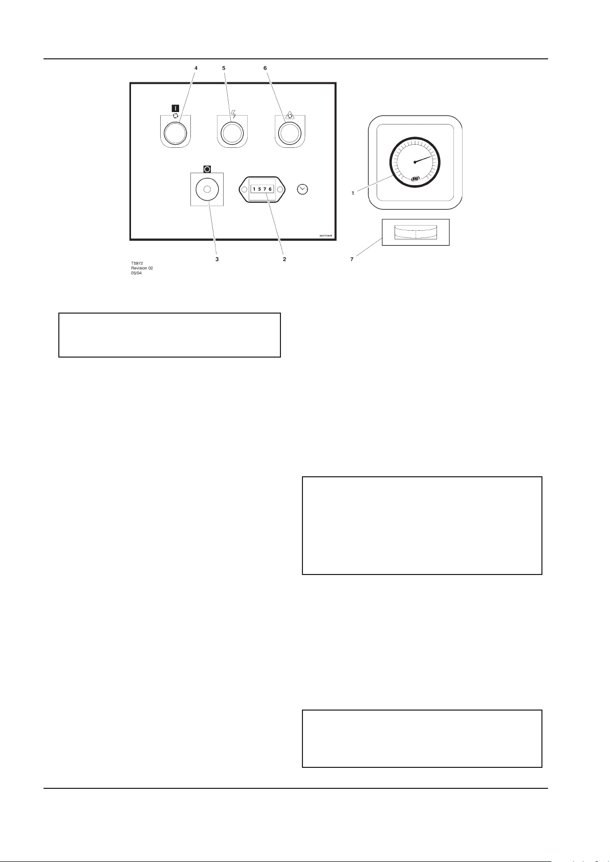
INSTRUCCIONES DE OPERACION MANUAL DE MANEJO Y MANTENIMIENTO
1. MANOMETRO
Indica la presión del sistema.
ADVERTENCIA
NO operar el compresor a temperaturas de
descarga superiores a la presión nominal.
2. CONTADOR HORARIO
Registra el tiempo total de funcionamiento del
compresor.
3. BOTÓN DE PARADA/PARADA DE EMERGENCIA
Cuando se pulsa, detendrá el compresor
inmediatamente. El indicador de encendido
permanecerá iluminado. El botón de parada
(STOP) debe soltarse antes de poder poner de
nuevo en funcionamiento el compresor.
4. INTERRUPTOR DEL BOTÓN DE ENCENDIDO
Cuando se pulsa, hará que la unidad arranque y
funcione encondición de carga si existe demanda
de aire. Si no existe demanda de aire, la máquina
se detendrá automáticamente.
5. LUZ INDICADORA DE ENCENDIDO (verde)
Indica la presencia de tensión de control.
cerciorarse de que todas las guardas están jas y
que nada obstruye la ventilación adecuada de la
máquina o el acceso libre a la misma.
2. Comprobar el nivel del refrigerante. Restablecerlo,
si fuere necesario.
3. Asegurarse de que la válvula de descarga de aire
se encuentra abierta.
4. Acoplar el aislador eléctrico o conectar.
Se encenderá el indicador (5) de Potencia
conectada, indicando que las tensiones de la
línea y de control se hallan disponibles.
5. Comprobar el sentido de rotación al arrancar
inicialmente o después de una interrupción del
suministro de corriente.
ADVERTENCIA
Asegurarse de que todas las cubiertas de
protección se encuentran en su lugar.
El escape del ujo de aire de refrigeración
puede contener restos volátiles. Debe utilizarse
protección de seguridad en todo momento para
evitar lesiones.
6. LUZ INDICADORA DE PARADA/REINICIO
ARRANQUE
AUTOMÁTICO (ámbar)
Se iluminará cuando la máquina se haya apagado
debido a una demanda de aire baja. La máquina
1. Pulse el botón de inicio (START). El compresor se
iniciará y se cargará automáticamente.
se reiniciará y se cargará automáticamente tan
pronto como vuelva a existir una demanda de aire.
7. INDICADOR DE PUNTO DE ROCÍO (opción de
secador)
El color verde indica un buen punto de rocío.
El color rojo indica que el punto de rocío se
encuentra por encima de 10°C (50°F). El color azul
indica congelación.
PARADA NORMAL/DE EMERGENCIA
1. Pulsar el botón de PARADA DE EMERGENCIA (3)
y el compresor se parará de inmediato.
2. Desconectar el aislador eléctrico.
PRECAUCION
Después de una parada, nunca se dejará que la
unidad permanezca inactiva con presión en el sis-
ANTES DEL ARRANQUE
tema del recipiente de almacenamiento/separador.
1. Realizar una inspección visual de la máquina,
40 http://air.ingersollrand.com
Page 89
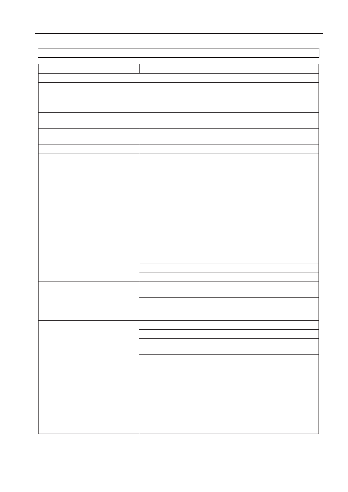
MANUAL DE MANEJO Y MANTENIMIENTO MANTENIMIENTO
MANTENIMIENTO
Programa de mantenimiento de la Serie UP
PERÍODO MANTENIMIENTO
Cada 24 horas de trabajo Comprobar el nivel de refrigerante, rellenar si es necessario.
Inspeccionar visualmente la máquina
Visual por si tiene fugas o acumulación
de polvo y comprobar si produce
ruidos o vibraciones inusuales.
Cuando el compresor sea con depósito
montado
Comprobar visualmente el estado del
ltro previo
Primeras 150 horas Cambiar el ltro de refrigerante.
Cada mes o 100 horas Desmontar y limpiar el ltro previo de la unidad y cambiarlo si fuese
Cada año o 2000 horas Vericar el funcionamiento del interruptorde protección de alta
Inspección externa anual e inspección
interna cada 6 años del recipiente
presurizado.
La frecuencia también puede establecerse
en función de la legislación local o nacional.
Cada dos años o 8000 horas Cambiar las correas de accionamiento.
Informar inmediatamente, contactar con el distribuidor autorizado de
Ingersoll Rand en busca de ayuda en caso de duda
Vaciar el condensado del recipiente almacenamiento del aire o
comprobar que esté funcionando el desagüe automático.
Limpiarlo con aire comprimido si se requiere
necesario. Revisar en el o los refrigeradores si hay acumulación de
materias extrañas. Limpiar si es necesario con aire o agua a presión.
temperatura del aire (109C).
Sustituir los elementos y los ltros IRGP y IRHE.
Cambiar el ltro del refrigerante.
Comprobar el tamiz de barrido por si sufre atascos y limpiarlo si
procede.
Cambiar el elemento separador.
Cambiar el elemento del ltro de aire.
Tomar una muestra del refrigerante para análisis del líquido.
Cambiar el ltro previo de la unidad.
Comprobar las correas de accionamiento.
Cambiar el cojinete sellado en motores sin engrasadora
Recipiente separador y recipiente de almacenamiento de aire si se han
montado.
Inspeccionar totalmente todas las supercies exteriores y accesorios.
Informar acerca de cualquier corrosión excesiva, daños mecánicos o de
impacto, fugas u otros deterioros.
Sustituir cada intervalo que ocurra primero.
Inspeccionar y cambiar todos los elementos incluidos dentro del
servicio de las 2000 horas.
Montar las siguientes piezas de reacondicionamiento, según proceda:
Solenoid valves
Kit de válvulas de solenoide
Kit de válvulas de entrada
Kit de válvulas de presión mínima
Montar las siguientes piezas de
reacondicionamiento según proceda:
Válvulas de solenoide
Kit de válvulas de admisión
Kit de válvula de presión mínima
Kit de válvula termostática
http://air.ingersollrand.com 41
Page 90
42 http://air.ingersollrand.com
MANTENIMIENTO MANUAL DE MANEJO Y MANTENIMIENTO
PERÍODO MANTENIMIENTO
Cada 4 años o 16000 horas Remplazar todos los manguitos.
Compruebe los motores con las guarniciones de la grasa y la grasa por
etiqueta de datos del motor.
Montar puntas de contactores eléctricos de
repuesto.
Cambiar el cojinete sellado en motores sin engrasadora
MANTENIMIENTO DE RUTINA
Esta sección se reere a los componentes que requieren
un mantenimiento y sustitución periódica.
Debería tenerse en cuenta que los intervalos
entre necesidades de servicio pueden reducirse
signicativamente como consecuencia del mal
ambiente de trabajo. Esto incluye efectos de
contaminación atmosférica y extremos de temperaturas.
La TABLA DE SERVICIO / MANTENIMIENTO indica la
descripción de los componentes y los intervalos en que
el mantenimiento tiene que realizarse. La capacidad de
los distintos tanques o depósitos, etc puede encontrarse
en la sección INFORMACION GENERAL de este manual.
El aire comprimido puede ser peligroso si no se utiliza
correctamente. Antes de realizar ningún tipo de trabajo
en la unidad, asegúrese de que se ha liberado toda la
presión del sistema y que la máquina no puede arrancar
accidentalmente.
PRECAUCION:
Cerciorarse de que el personal de mantenimiento esté
adecuadamente adiestrado, sea competente y lea los
Manuales de Mantenimiento.
Antes de empezar cualquier tarea de mantenimiento,
cerciórese de:–
que se alivie toda la presión de aire y se aisle
•
de presiones el sistema. Si para ello se usa el
purgador automático, hay que darle tiempo
suciente para efectuar el alivio total.
la máquina no se puede arrancar
•
accidentalmente o de otro modo.
que se desconecten o aislen las fuentes de
•
electricidad (batería y tomas de energía eléctrica).
Antes de abrir o quitar tapas o cubiertas para meter
manos en la máquina, cerciórese de:–
que quienes pongan manos en la máquina
•
sepan que están ahora más expuesto a tales
riesgos como de tocar supercies calientes y
movimientos intermitentes de mecanismos.
Antes de realizar cualquier trabajo de
mantenimiento en el compresor, abrir, bloquear y
precintar el interruptor de desconexión eléctrica
principal y cerrar la válvula de aislamiento de
la descarga del compresor.Ventilar la presión
de la unidad abriendo lentamente una vuelta
completa del tapón de llenado del refrigerante.
Al desenroscar el tapón de llenado, se abre un
agujero de ventilación taladrado sobre el tapón,
permitiendo que la presión sea liberada a la
atmósfera. No quitar el tapón de llenado hasta
que se haya liberado toda la presión de la unidad
a la atmósfera. Ventilar además los conductos
abriendo ligeramente la válvula de vaciado. Al
abrir la válvula de vaciado o el tapón de llenado,
mantenerse alejado de la descarga de la válvula y
llevar puesta la protección adecuada para los ojos.
AVISO:
Puede que esta máquina tenga un circuito
monofásico separado para el secador y/o para
la válvula de drenaje eléctrica. Antes de realizar
cualquier trabajo en la máquina, es imprescindible
desconectar el suministro de energía de todos
los circuitos, así como identicar el dispositivo de
desconexión.
la máquina no se puede arrancar
•
accidentalmente o de otro modo.
Antes de empezar alguna operación de
mantenimiento en una máquina que está en marcha,
cerciórese de:–
PELIGRO
Sólo personas adecuadamente adiestradas y
competentes deberán encargarse de tareas de
mantenimiento estando el compresor funcionando
o con la energía eléctrica conectada.
Que sólo se hagan operaciones para las que sea
•
necesario tener la máquina en marcha.
Que, si se harán operaciones para las que se
•
quitarán o suprimirán dispositivos de protección,
sólo sean operaciones para las que sea necesario
tener la máquina en marcha con dispositivos de
seguridad suprimidos o quitados.
Que estén conscientes de todos los peligros (p.
•
ej. dispositivos con presión, piezas eléctricas con
corriente, guardas, tapas y cubiertas quitadas,
temperaturas extremas, aspiración y descarga
de aire, piezas en movimiento intermitente,
descarga por la válvula de seguridad, etc.).
Que se use ropa y equipo de protección personal.
•
Page 91
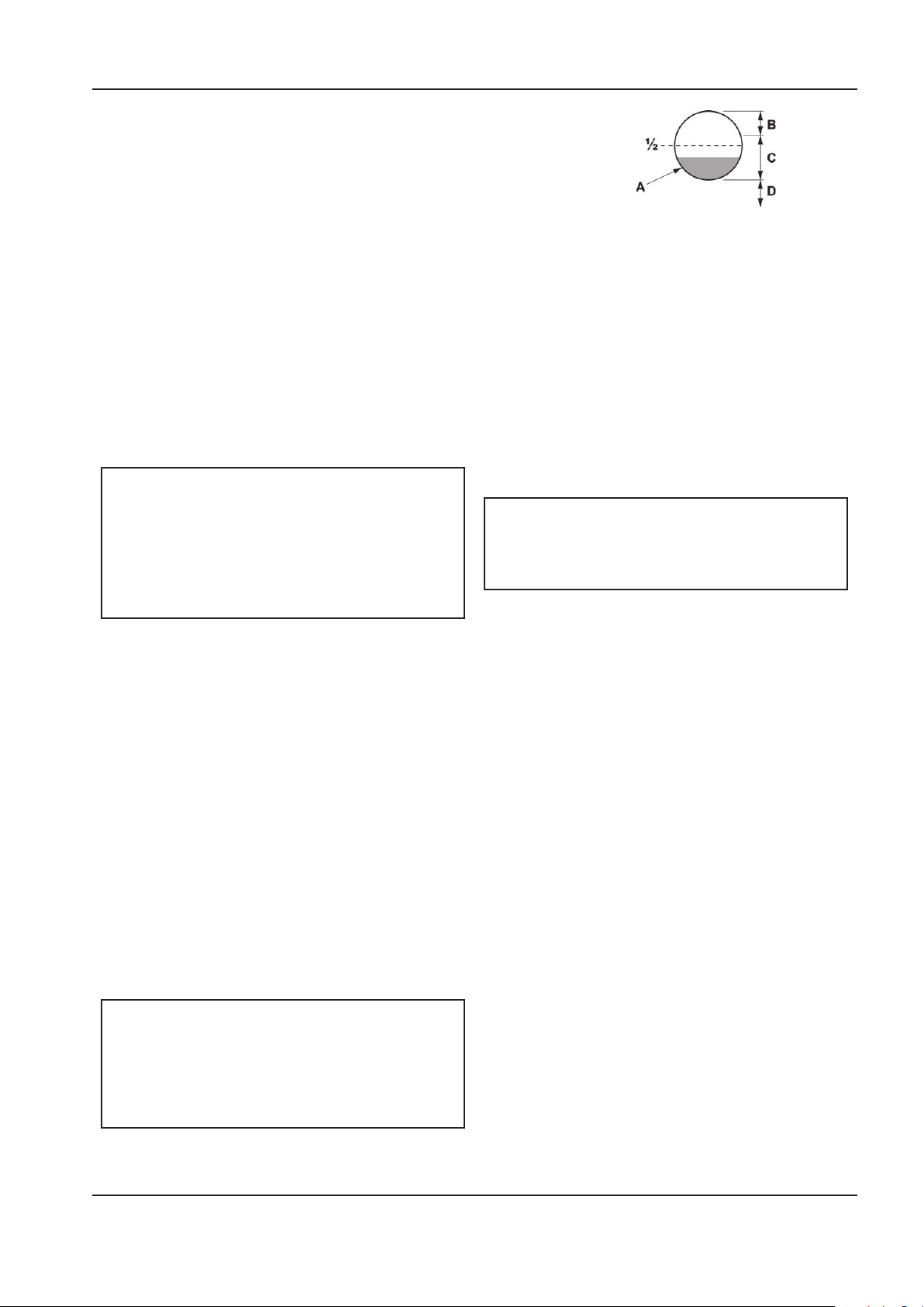
MANUAL DE MANEJO Y MANTENIMIENTO MANTENIMIENTO
A. Temperatura de funcionamiento correcta
B. Demasiado
C. Adecuado
D. Demasiado poco
Que se quiten o atajen pulseras, ropa suelta,
•
cadenitas, etc. y se recojan el cabello si lo tienen
largo.
•
Que se pongan letreros de prevención (p. ej.
Máquina Reparándose) donde sean bien visibles.
Al terminar tareas de mantenimiento y antes de
ponerse la máquina otra vez a trabajar, cerciórese de:–.
Probar apropiadamente la máquina.
•
•
se han montado de nuevo y funcionan
correctamente todas las defensas y dispositivos
de protección de la seguridad.
•
Colocar todas las tapas y cerrar el capot y las
compuertas.
•
Los materiales de riesgo se contienen y desechan
ecazmente de manera que se cumplan los
códigos locales o nacionales de protección del
medio ambiente.
ADVERTENCIA
Repetir este procedimiento para que el líquido
refrigerante llegue al nivel adecuado a temperatura de
funcionamiento.
Por lo general, cuando se apaga la unidad, el líquido
refrigerante llena la mirilla. No ajustar el nivel de
refrigerante basándose en el nivel que se muestra
con la unidad apagada. El nivel adecuado debe jarse
siempre con la unidad encendida a temperatura de
funcionamiento.
No abrir en ningún caso ninguna válvula ni
desmontar componentes del compresor sin
asegurar primero de que el compresor está
COMPLETAMENTE PARADO, la alimentación
desconectada y des presurizado todo el sistema
de aire.
PROCEDIMIENTO PARA RESTABLECER EL NIVEL
DEL REFRIGERANTE
Retirar lentamente el tapón de llenado.
1.
Verter líquido refrigerante en el conducto hasta
2.
que casi se desborde.
Sustituir y apretar el tapón de llenado de aceite.
3.
Poner en funcionamiento la unidad durante 10
4.
segundos aproximadamente (hasta que el líquido
refrigerante se drene por la parte inferior de la
mirilla).
Retirar lentamente el tapón de llenado.
5.
Volver a llenar el conducto de refrigerante hasta
6.
que casi se desborde.
Sustituir y apretar el tapón de llenado.
7.
Hacer funcionar la unidad.
8.
NOTA:
El nivel de líquido refrigerante es el correcto
cuando se muestra líquido refrigerante en
la mitad inferior de la mirilla de la unidad a
temperatura de funcionamiento (tras diez
minutos funcionando cargada).
PRECAUCION
Cerciorarse de que se usa el nuevo refrigerante
SSR ULTRA. De no hacerlo así, se invalidaría la
garantía del fabricante.
PROCEDIMIENTO DE CAMBIO DEL REFRIGERANTE
Es mejor drenar el refrigerante inmediatamente
después de que el compresor haya estado funcionando
ya que el líquido drenará más fácilmente y cualquier
contaminante permanecerá en suspensión en el mismo.
Parar la máquina, aislarla eléctricamente y disipar
1.
toda la presión atrapada.
Colocar un recipiente adecuado cerca de la
2.
válvula de purga.
Retirar lentamente el tapón de llenado.
3.
Quitar el tapón de la válvula de purga.
4.
Abrir la válvula de purga y vaciar el refrigerante
5.
en el recipiente.
Cerrar la válvula de purga..
6.
Montar de nuevo el tapón en la válvula de purga.
7.
Rellenar la máquina siguiendo el procedimiento
8.
anterior para “restablecer el nivel del refrigerante.
Tras el llenado inicial, para purgar cualquier tapón
de aire, se deberá hacer funcionar la máquina
durante unos minutos realzando el ciclo entre
carga y no carga, antes de comprobar que el nivel
sea el correcto.
Sustituir y apretar el tapón de llenado.
9.
http://air.ingersollrand.com 43
Page 92

44 http://air.ingersollrand.com
MANTENIMIENTO MANUAL DE MANEJO Y MANTENIMIENTO
PROCEDIMIENTO DE CAMBIO DEL FILTRO DE
REFRIGERANTE
Parar la máquina, aislarla eléctricamente y disipar
1.
toda la presión atrapada.
Aojar el ltro usando la herramienta correcta.
2.
Retirar el ltro del alojamiento.
3.
Meter el ltro usado en una bolsa hermética y
4.
desecharlo de forma segura.
Limpiar las supercies coincidentes del
5.
alojamiento teniendo cuidado de que no penetre
partícula alguna en la máquina.
Extraer el nuevo ltro de repuesto de Ingersoll
6.
Rand de su paquete protector.
Aplicar una pequeña cantidad de lubricante en la
7.
junta de estanqueidad del ltro.
Enroscar el nuevo ltro hasta que la junta de
8.
estanqueidad haga contacto con el alojamiento y
luego apretarlo media vuelta más con la mano.
Arrancar el compresor y comprobar las posibles
9.
fugas.
entre en contacto con la caja y, seguidamente,
apretar con la mano media vuelta más.
Poner en marcha el compresor y inspeccionarlo
8.
por si tiene fugas.
PRECAUCION
Esta unidad no se ha diseñado ni propuesto
para funcionar cuando esté contaminada
de silicona. Los lubricantes, grasas y otros
productos que contengan silicona no deberán
utilizarse con esta unidad.
PROCEDIMIENTO DE LIMPIEZA DEL REFRIGERADOR
Parar la máquina, aislarla eléctricamente y disipar
1.
toda la presión atrapada.
Quitar la tapa superior para lograr acceso al
2.
refrigerador.
Limpiar el refrigerador.
3.
Montar todo otra vez siguiendo el orden inverso.
4.
PROCEDIMIENTO DE VERIFICACION Y AJUSTE DE
CORREAS
PROCEDIMIENTO DE CAMBIO DEL ELEMENTO
DEL FILTRO
Parar la máquina, aislarla eléctricamente y disipar
1.
toda la presión atrapada.
Desenrosque la tuerca de retenida y retire el
2.
elemento antiguo.
Montar el nuevo elemento.
3.
Colocar de nuevo la tapa de retención.
4.
PROCEDIMIENTO DE SUSTITUCIÓN DEL ELEMENTO SEPARADOR
Parar la máquina, aislarla eléctricamente y disipar
1.
toda la presión atrapada.
Aojar el elemento separador con la herramienta
2.
adecuada.
Extraer el elemento de la caja, colocarlo en una
3.
bolsa sellada y deséchelo de manera segura.
Limpiar las supercies coincidentes del
4.
alojamiento.
Extraer el nuevo elemento de repuesto de
5.
Ingersoll Rand de su paquete protector.
Aplicar una pequeña cantidad de lubricante al
6.
sello del elemento.
Atornillar el nuevo elemento hasta que el sello
7.
Vericar de vez en cuando la tensión de las correas,
especialmente si se sospecha que estén ojas. Se
puede realizar una vericación rápida para determinar
si el ajuste es correcto, observando el lado ojo de la
correa por si se forma un ligero arco cuando la unidad
esté en funcionamiento. Si este ligero arco resulta
evidente, la correa está, por regla general, ajustada
satisfactoriamente.
Se puede utilizar un dispositivo de medición de la
tensión de la correa para determinar la tensión de la
misma.
La tensión de la correa se puede conseguir aojando los
pernos de anclaje de la unidad compresora; se incluye
un perno de tensión de la correa para ayudar a mover la
unidad compresora.
Seguir el procedimiento siguiente para jar y medir
correctamente la tensión de la correa.
1. Poner una regla a lo ancho de la supercie
superior exterior del accionamiento de la correa
desde la polea hasta la roldana.
2. En el centro de ese tramo, aplicar,
perpendicularmente a la correa, presión a
la supercie exterior de la correa usando un
medidor de la tensión. Obligar la correa a la
desviación indicada en el cuadro de abajo y
comparar la lectura del medidor de la tensión con
las cifras que se indican.
Page 93
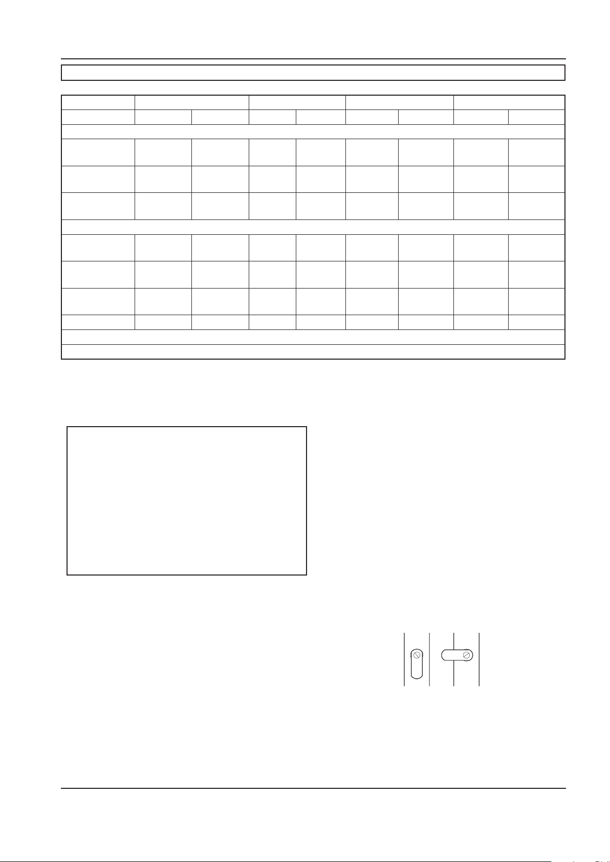
MANUAL DE MANEJO Y MANTENIMIENTO MANTENIMIENTO
Válvula esférica del puricador
ABIERTA CERRADA
TENSIÓN DE LA CORREA
5hp/4kw * 7.5hp/5.5kw * 10hp/7.5kw * 15hp/11kw **
Nueva Usada Nueva Usada Nueva Usada Nueva Usada
60hz
125 psig 75 Lb
(34 Kg)
150 psig 75 Lb
(34 Kg)
210 psig 75 Lb
(34 Kg)
50hz
8 bar 85 Lb
(39 Kg)
10 bar 90 Lb
(41 Kg)
14.5 bar 90 Lb
(41 Kg)
* Tensiómetro “Krikit I” o equivalente
** Tensiómetro “Krikit II” o equivalente
62 Lb
(28 Kg)
62 Lb
(28 Kg)
62 Lb
(28 Kg)
70 Lb
(32 Kg)
75 Lb
(34 Kg)
75 Lb
(34 Kg)
110 Lb
(50 Kg)
90 Lb
(41 Kg)
90 Lb
(41 Kg)
85 Lb
(39 Kg)
85 Lb
(39 Kg)
100 Lb
(45 Kg)
90 Lb
(41 Kg)
75 Lb
(34 Kg)
75 Lb
(34 Kg)
70 Lb
(32 Kg)
70 Lb
(32 Kg)
80 Lb
(36 Kg)
110 Lb
(50 Kg)
110 Lb
(50 Kg)
110 Lb
(50 Kg)
110 Lb
(50 Kg)
120 Lb
(54 Kg)
120 Lb
(54 Kg)
90 Lb
(41 Kg)
90 Lb
(41 Kg)
90 Lb
(41 Kg)
90 Lb
(41 Kg)
100 Lb
(45 Kg)
100 Lb
(45 Kg)
140 Lb
(64 Kg)
140 Lb
(64 Kg)
150 Lb
(68 Kg)
140 Lb
(64 Kg)
140 Lb
(64 Kg)
150 Lb
(68 Kg)
120 Lb
(54 Kg)
120 Lb
(54 Kg)
125 Lb
(57 Kg)
120 Lb
(54 Kg)
120 Lb
(54 Kg)
125 Lb
(57 Kg)
Antes de arrancar de nuevo el compresor, cerciorarse de
que la polea y la roldana estén correctamente alineadas
y de que los tornillos de anclaje del motor queden
adecuadamente apretados.
PRECAUCION
Siendo incorrectas la alineación de la polea/
roldana y la tensión de la correa puede ocasionar
sobrecarga del motor, vibración excesiva y fallo
prematuro de la correa y/o de rodamientos.
Para evitar la ocurrencia de estos problemas,
cerciorarse de que
resulten satisfactorias la alineación de la polea y
de la roldana y la tensión de la correa después de
instalar nuevas correas o de tensar las correas ya
existentes.
VÁLVULA ELÉCTRICA DE VACIADO (OPCIONAL)
DESCRIPCION DEL PRODUCTO
La válvula eléctrica de vaciado (EDV) elimina el
líquido refrigerante y el agua condensados del tanque
acumulador de aire. Se pueden instalar drenajes
adicionales en todo el sistema de aire comprimido,
incluyendo posrefrigeradores, ltros, tuberías de
vaciado y secadores.
La válvula eléctrica de vaciado opera bajo un
temporizador que puede regularse para que vacíe
automáticamente el tanque colector de aire a intervalos
designados por el operador.
Las características clave incluyen:
100% trabajo continuo
•
Envolvente según NEMA 4
•
Tiempo regulable encendido (0.5 – 10 segundos)
•
Tiempo regulable apagado (0.5 – 45 minutos)
•
Operador de acero inoxidable
•
Diodo emisor de luz (LED) para indicar que la
•
corriente eléctrica está conectada
Diodo emisor de luz (LED) para indicar que la
•
válvula está abierta
Sobremultiplicador manual
•
FUNCIONAMIENTO
Abrir la válvula esférica del puricador.
1.
2. Ajustar los botones de tiempo “apagado” y
“tiempo encendido”. Véanse los AJUSTES DEL
TEMPORIZADOR (abajo) para una explicación de
los valores.
3. Durante el funcionamiento del compresor,
comprobar si hay fugas de aire.
http://air.ingersollrand.com 45
Page 94

46 http://air.ingersollrand.com
MANTENIMIENTO MANUAL DE MANEJO Y MANTENIMIENTO
AJUSTES DEL TEMPORIZADOR
El ajuste de “tiempo apagado” determina el intervalo
entre ciclos desde 30 segundos hasta 45 minutos. El
ajuste del “tiempo encendido” determina el tiempo en sí
que el compresor vacía condensado.
La relación del ciclo del temporizador y del tiempo de
apertura del desagüe deberá ajustarse para que se abra
justamente durante el tiempo sucientemente largo
para descargar el condensado. El temporizador está
adecuadamente ajustado cuando se abre y descarga
condensado y luego ventila aire durante un segundo
aproximadamente antes de cerrarse. Los ajustes pueden
realizarse en función de muchos factores, la humedad y
el ciclo de trabajo incluidos.
LOCALIZACION DE FALLOS
FALLO CAUSA ACCION
La válvula no
se cierra.
El temporizador no se
activa
MANTENIMIENTO
Limpiar periódicamente el tamiz del interior de la
válvula para mantener el desagüe funcionando
a máxima capacidad. Para ello, realizar los pasos
siguientes:
Cerrar por completo la válvula esférica del
1.
puricador para aislarla del tanque colector del
aire.
Suciedad que
en la válvula de
solenoide impide
el asiento del
diafragma.
Cortocircuito en
un componente
eléctrico.
No hay suministro
eléctrico.
Funcionamiento
defectuoso del
temporizador
Lumbrera obstruida.
Funcionamiento
defectuoso de la
válvula de solenoide.
Puricador obstruido.
Retirar la válvula
de solenoide, desarmarla, limpiarla y montarla de
nuevo.
Comprobar y
cambiar el cable de
corriente o el temporizador, según
proceda.
Aplicar la corriente.
Cambiar el
temporizador.
Limpiar la válvula.
Cambiar la válvula
de solenoide.
Limpiar el puricador.
PRECAUCION!
El aire a alta presión puede ocasionar lesiones
a causa de piezas volantes. Cerciorarse de
que la válvula esférica del puricador esté
completamente cerrada y de que se elimina la
presión de la válvula antes de realizar limpieza.
3. Quitar el tapón del puricador utilizando una
llave adecuada. Si se oye salir aire de la lumbrera
de limpieza, PARAR INMEDIATAMENTE y repetir
los pasos 1 y 2.
4. Quitar el tamiz del ltro de acero inoxidable y
limpiarlo. Elimina toda suciedad que pueda haber
en el cuerpo del puricador antes de montar de
nuevo el tamiz del ltro.
5. Montar de nuevo el tapón y apretarlo con la llave.
6. Al volver a poner la Válvula Eléctrica de Vaciado
en funcionamiento, pulsar el botón de PRUEBA
para conrmar que funciona correctamente.
Antes de acceder a piezas eléctricas, desconectar
la alimentación eléctrica al secador utilizando el
interruptor de desconexión o desconectando las
conexiones de cables.
MANTENIMIENTO PREVENTIVO
Para obtener óptimo rendimiento del secador, respétese
el programa de mantenimiento periódico que se
describe a continuación:
SEMANALMENTE DESAGÜES DEL CONDENSADO-
Comprobar que los desagües del
condensado funcionan correctamente.
CADA 4 MESES CONDENSADOR
Limpiar el polvo acumulado en
las aletas del condensador.
COMPRESOR
Cerciorarse de que el consumo
de energía del compresor
cumple lo especicado en la
chapa de datos.
ANUALMENTE DESAGÜES DEL CONDENSADO
Desmontar por completo los
desagües y limpiar todos sus
componentes.
FILTRO DE AIRE
Cambiar el elemento del ltro de
aire.
Pulsar el botón de PRUEBA en el temporizador
2.
para ventilar la presión remanente en la válvula.
Repetir la operación hasta que se haya eliminado
toda la presión.
MANTENIMEINTO DEL SEPARADOR DE LA HUMEDAD
El separador de la humedad funcionará indenidamente
bajo condiciones normales de trabajo, aunque en algún
momento tal vez se requiera cambiar las juntas de
estanqueidad en caso de que la carcasa mostrase fugas.
Page 95
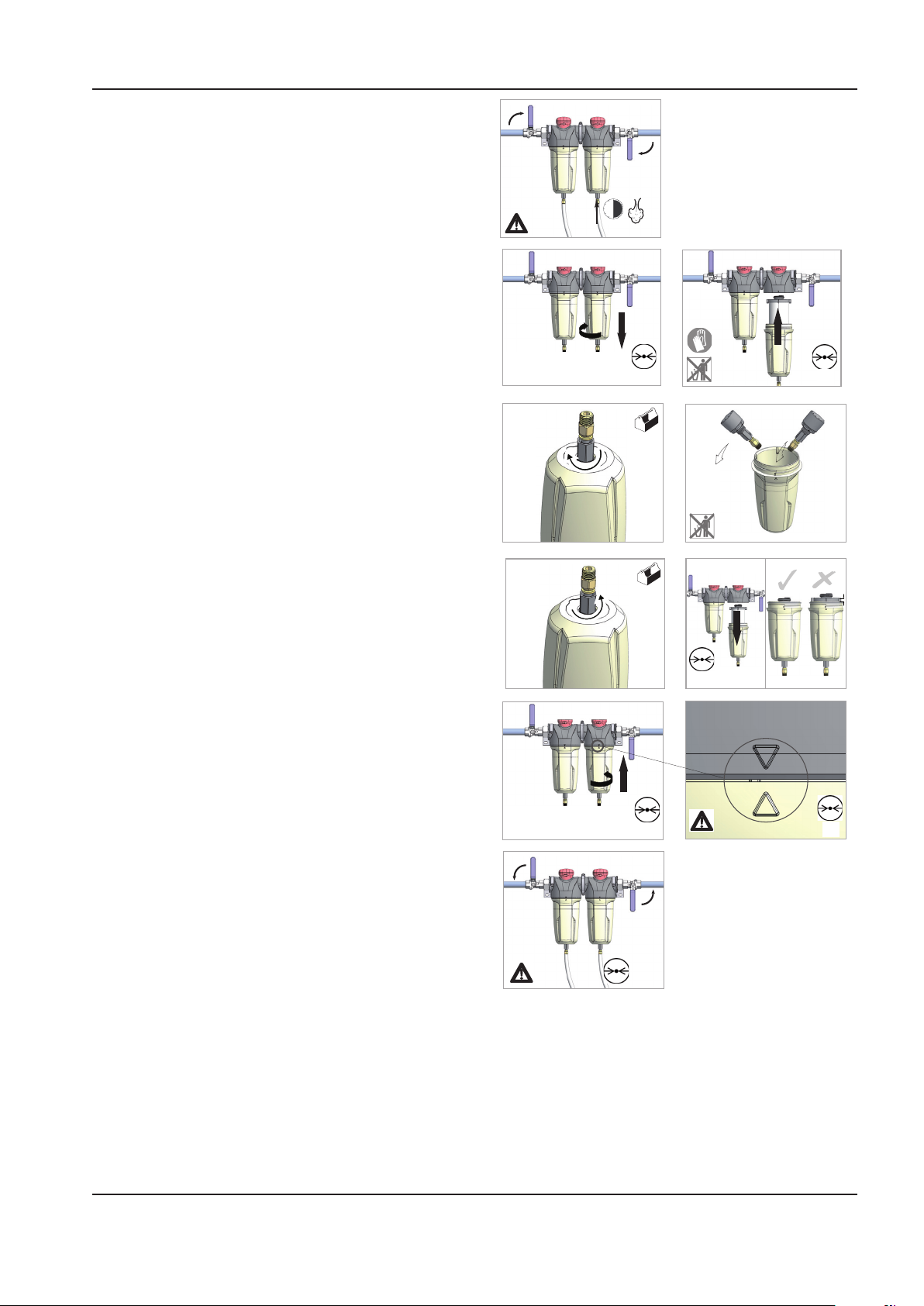
MANUAL DE MANEJO Y MANTENIMIENTO MANTENIMIENTO
1
2
2
3
> 30s
4
5
0 bar
0 psi
1
2
0 bar
0 psi
7 8
0 bar
0 psi
9 10
2
1
0 bar
0 psi
0 bar
0 psi
1
2
12
5 6
1
Aislar la carcasa del suministro de aire.
1.
Eliminar por completo la presión de la cubeta de
2.
desagüe según proceda.
Desenroscar la cubeta y retirarla. Si no se ha
3.
liberado la presión de la cubeta por completo,
el aire se escapará por el agujero de aviso
produciendo una alarma sonora. Enroscar otra
vez la cubeta y repetir la instrucción 2 antes de
intentarlo de nuevo. Si se experimenta resistencia
al desenroscarla, se provee una llave en forma de
’C’ que encaja en los refuerzos de la cubeta.
Comprobar el estado de las juntas de
4.
estanqueidad de la cubeta y cambiarlas si fuere
necesario. Limpiar las roscas.
Montar otra vez la cubeta junto con la junta
5.
tórica.
Someterla a presión de nuevo y comprobar si
6.
sufre fugas. En caso positivo, lo más probable
es que ocurran por la junta tórica de la cubeta.
Eliminar la presión de la carcasa y quitar la junta
tórica e inspeccionar y limpiar. Cerciorarse de que
las supercies coincidentes estén limpias y luego
montar la junta tórica y someter a presión otra vez.
MANTENIMIENTO DEL FILTRO DE AIRE
Con el n de asegurar la óptima calidad del aire,
deberá cambiarse el ltro de aire como se indica a
continuación. (Los elementos del ltro usados deberán
desecharse de conformidad con las normas locales).
Utilizar únicamente elementos de repuesto genuinos de
Ingersoll Rand.
DESMONTAJE DE LA UNIDAD
La unidad ha sido concebida y fabricada para garantizar
un funcionamiento continuo.
La larga duración en servicio de algunos componentes,
tales como el ventilador y el compresor, está en función
de un buen mantenimiento.
La unidad sólo deberá ser desmontada por un
especialista en refrigeración.
http://air.ingersollrand.com 47
Page 96
48 http://air.ingersollrand.com
MANTENIMIENTO MANUAL DE MANEJO Y MANTENIMIENTO
El líquido refrigerante y el aceite lubricante del interior
del circuito de refrigeración han de recuperarse de
conformidad con las normas actuales del país en el que
la máquina sea instalada.
DESMONTAJE DE RECICLAJE
Bastidor y paneles Acero / poliéster de resina
epoxidica
Cambiador de calor
(refrigerador)
Tuberías Cobre
Aislante Goma sintética
Compresor Acero / cobre / aluminio /
Condensador Aluminio
Refrigerante R134a
Válvula Acero
Acero inoxidable
aceite
FUGAS DE REFRIGERANTE EN EL CIRCUITO DE
REFRIGERACION
La unidad se despacha ya cargada y en perfectas
condiciones de trabajo.
Las fugas del refrigerante pueden identicarse
al desconectarse el protector de sobrecarga de
refrigeración.
SI SE DETECTA UNA FUGA EN EL CIRCUITO DE
REFRIGERACION, SOLICITE ASISTENCIA TECNICA.
LOCALIZACION DE FALLOS
FALLO CAUSA ACCION
La válvula de
condensado
de solenoide
no se cerrará.
El
temporizador
de drenaje no
funcionará
Suciedad que en la
válvula de solenoide
impide el asiento
del diafragma.
Cortocircuito en
un componente
eléctrico.
No hay suministro
eléctrico.
Funcionamiento
defectuoso del
temporizador
Lumbrera obstruida. Limpiar la
Funcionamiento
defectuoso de la
válvula de solenoide.
Puricador
obstruido.
Retirar la válvula
de solenoide,
desarmarla,
limpiarla y
montarla de
nuevo.
Comprobar y
cambiar el cable
de corriente o el
temporizador,
según proceda.
Aplicar la
corriente.
Cambiar el
temporizador.
válvula.
Cambiar la
válvula de
solenoide.
Limpiar el
puricador.
CARGA DE REFRIGERANTE
ESTA OPERACION SOLO DEBERA REALIZARLA UN
ESPECIALISTA EN REFERIGERACION.
CUANDO SE REPARE EL CIRCUITO DE REFRIGERACION,
RECOGER TODO EL REFRIGERANTE EN UN RECIPINTE
Y DESECHARLO DE LA MANERA APROPIADA.
CARACTERISTICAS DEL REFRIGERANTE R134A
Bajo condiciones normales de temperatura y presión, el
citado refrigerante es un gas incoloro de la clase A1/A1
gas con un valor TVL de 1.000ppm (clasicación de
ASHRAE).
Si ocurre una fuga de refrigerante, ventilar bien la sala
antes de comenzar trabajo alguno.
MANTENIMIENTO
Limpiar periódicamente el tamiz del interior de la
válvula para mantener el desagüe funcionando
a máxima capacidad. Para ello, realizar los pasos
siguientes:
Cerrar por completo la válvula esférica del
1.
puricador para aislarla del tanque colector del
aire.
Pulsar el botón de PRUEBA en el temporizador
2.
para ventilar la presión remanente en la válvula.
Repetir la operación hasta que se haya eliminado
toda la presión.
Page 97

MANUAL DE MANEJO Y MANTENIMIENTO MANTENIMIENTO
PRECAUCION!
El aire a alta presión puede ocasionar lesiones
a causa de piezas volantes. Cerciorarse de
que la válvula esférica del puricador esté
completamente cerrada y de que se elimina la
presión de la válvula antes de realizar limpieza.
3. Quitar el tapón del puricador utilizando una
llave adecuada. Si se oye salir aire de la lumbrera
de limpieza, PARAR INMEDIATAMENTE y repetir
los pasos 1 y 2.
4. Quitar el tamiz del ltro de acero inoxidable y
limpiarlo. Elimina toda suciedad que pueda haber
en el cuerpo del puricador antes de montar de
nuevo el tamiz del ltro.
5. Montar de nuevo el tapón y apretarlo con la llave.
6. Al volver a poner la Válvula Eléctrica de Vaciado
en funcionamiento, pulsar el botón de PRUEBA
para conrmar que funciona correctamente.
http://air.ingersollrand.com 49
Page 98
RESOLUCION DE AVERIAS MANUAL DE MANEJO Y MANTENIMIENTO
RESOLUCION DE AVERIAS
AVERIA CAUSA REMEDIO
El compresor no
arranca
La máquina se para
peródicamente
Alto consumo de
corriente
Bajo consumo de
corriente
Alta presión de
descarga
No disponible la tensión de la red
principal o de control.
Temporizador defectuoso de estrelle/
triángulo.
Alta temperatura del ”airend”
Restablecer el nivel del refrigerante.
Sobrecarga del motor. § Fijar la sobrecarga en el valor correcto y
Variacion de tensión de línea. § Cerciorarse de que la tensión no cae
Compresor funcionando a presión
superior a la nominal.
Elemento separador contaminado. Cambiar el ltro de aire y el elemento
Baja tensión. § Cerciorarse de que la tensión no cae
Tensión desequilibrada. Tensión correcta del suministro entrante.
”Airend” dañado † Cambiar la unidad compresora.
Contaminación del ltro de aire. Cambiar el ltro de aire.
Compresor funcionando sin carga. Fijar la presión en el régimen correcto para la
Alta tensión. Reducir la tensión del sitio hasta la tensión
Válvula de admisión defectuosa † Montar el kit de servicio de la válvula de
Ajuste defectuoso o incorrecto del
interruptor de presión.
Válvula de purga defectuosa. † Montar el kit de servicio de la válvula de
Funcionamiento defectuoso de la
válvula de admisión.
§
Comprobar el suministro eléctrico entrante.
§
Comprobar el fusible del circuito de control.
§
Comprobar el devanado secundario del
transformador para la tensión de control.
§ Change Star / Delta timer.
Restablecer el nivel del refrigerante.
cambiar a reposición manual.
por debajo del 10% al arrancar y del 6%
funcionando.
Fijar la presión en el régimen correcto para la
máquina.
separador.
por debajo del 10% al arrancar y del 6%
funcionando.
máquina.
correcta de trabajo.
admisión.
Cambiar o jar la presión en el régimen
correcto para
la máquina.
solenoide de
seguridad.
† Montar el kit de servicio de la válvula de
admisión.
50 http://air.ingersollrand.com
Page 99
MANUAL DE MANEJO Y MANTENIMIENTO RESOLUCION DE AVERIAS
Baja presión de aire
del sistema
Punto de rocío alto El compresor de refrigeración no recibe
Formación de hielo
en el secador
Elemento separador contaminado. Montar el nuevo elemento separador.
Ajuste incorrecto del interruptor de
presión.
Funcionamiento defectuoso de la
válvula de presión mínima.
Válvula de purga defectuosa. † Montar el kit de servicio de la válvula de
La correa de accionamiento patina. Montar la nueva correa.
Fugas en el sistema de aire. † Reparar fugas.
Funcionamiento defectuoso de la
válvula de admisión.
La demanda del sistema supera la
descarga del
compresor.
Filtros de aire comprimido
contaminados.
corriente.
Funcionamiento defectuoso del sistema
de condensación.
Condensador sucio. Limpiar el condensador y sustituir el
Baja presión del evaporador. Comprobar el ajuste de la válvula de gas
Fijar la presión en el régimen correcto para la
máquina.
† Montar el kit de servicio de la válvula de
presión mínima.
solenoide de purga.
† Montar el kit de servicio de la válvula de
admisión.
Reducir la demanda o instalar un compresor
adicional.
Sustituir los elementos del ltro de aire.
Comprobar el suministro eléctrico entrante.
Comprobar el fusible de protección del
secador.
Comprobar el contacto auxiliar del contactor
principal del motor.
Comprobar el funcionamiento de la válvula
de drenaje.
Comprobar el funcionamiento de las válvulas
de retención de condensación.
elemento del ltro del panel.
caliente.
NOTAS:
§ Ha de llevarlo a cabo un electricista competente.
† Se recomienda que este trabajo sea realizado únicamente por un técnico de servicio autorizado de Ingersoll
Rand.
PRECAUCION
APLICACIONES DE BAJA DEMANDA
Durante los periodos de baja demanda, el compresor puede no alcanzar su normal temperatura
de funcionamiento. El funcionamiento sostenido a baja demanda puede tener como resultado la
acumulación de condensación en el refrigerante. Si ocurre esta situación, las características de lubricación
del refrigerante puede deteriorarse que puede llevar a daños en el compresor.
AL COMPRESOR DEBE PERMITÍRSELE UN AMPLIO TIEMPO DE FUNCIONAMIENTO DE AL MENOS 10
MINUTOS POR HORA DURANTE EL USO NORMAL DIARIO.
http://air.ingersollrand.com 51
Page 100
RESOLUCION DE AVERIAS MANUAL DE MANEJO Y MANTENIMIENTO
AVERIA CAUSA REMEDIO
El compresor se
dispara debido a
temperatura excesiva.
Excessive coolant
consumption
Excessive noise level Air system leaks. † Reparar fugas.
Shaft seal leaking Defective shaft seal. † Montar el juego de servicio de juntas de
Pressure relief valve
opens
Black residue on belt
guard/cooler box
Safety valve blows
when compressor
goes on load
Compresor funcionando a presión superior a la nominal.
Filtro previo de la unidad atascado. Limpiar/Cambiar el ltro previo de la unidad.
Refrigerador atascado. Limpiar el refrigerador.
Faltan o están incorrectamente monta-
dos los paneles de la envolvente.
Bajo nivel del refrigerante. Restablecer el nivel del refrigerante y com-
Alta temperatura ambiente. Cambiar de sitio el compresor.
Flujo restringido del aire refrigerante. Asegurar el caudal correcto de aire al com-
Separator element leak. Montar el nuevo elemento separador.
Blocked separator element drain. † Retirar accesorios y limpiarlos.
Compressor operating below rated pres-
sure.
Coolant system leak. † Reparar fugas.
Airend defective. † Cambiar la unidad compresora.
Belts Slipping. Cambiar correa y tensor.
Motor defective. † Cambiar el motor.
Loose components. † Apretar de nuevo los elementos que estén
Defective switch or incorrect pressure
switch setting.
Minimum pressure valve malfunction. † Montar el kit de servicio de la válvula de
Blowdown valve defective. † Montar el kit de servicio de la válvula de
Inlet valve malfunction. † Montar el kit de servicio de la válvula de
Pressure relief valve defective. Comprobar el ajuste de la válvula de seguri-
Drive belt slipping. Cambiar correa y tensor.
Pulleys misaligned. Alinear de nuevo las poleas.
Worn pulleys. † Cambiar poleas y correa.
Minimum pressure valve stuck closed. Desmontar la válvula de presión mínima,
Safety valve faulty Comprobar el ajuste de la válvula de seguri-
Fijar la presión en el régimen correcto para la
máquina.
Cerciorarse de que todos los paneles de la
envolvente estén correctamente contados.
probar si existen fugas.
presor.
Fijar la presión en el régimen correcto para la
máquina.
ojos.
estanqueidad de la unidad compresora.
Cambiar o jar la presión en el régimen cor-
recto para la máquina.
presión mínima
solenoide de seguridad.
admisión.
dad de presión y la presión de régimen.
examinarla y repararla si es necesario.
dad y la presión de régimen.
NOTAS:
§ Ha de llevarlo a cabo un electricista competente.
†
Se recomienda que este trabajo sea realizado únicamente por un técnico de servicio autorizado de Ingersoll Rand.
52 http://air.ingersollrand.com
 Loading...