

Ingersoll-Rand TEM6A0B24H21S, TEM6A0C48H41S, TEM6A0B30H21S, TEM6A0D48H41S, TEM6A0D60H51S Installer's Manual
...Page 1
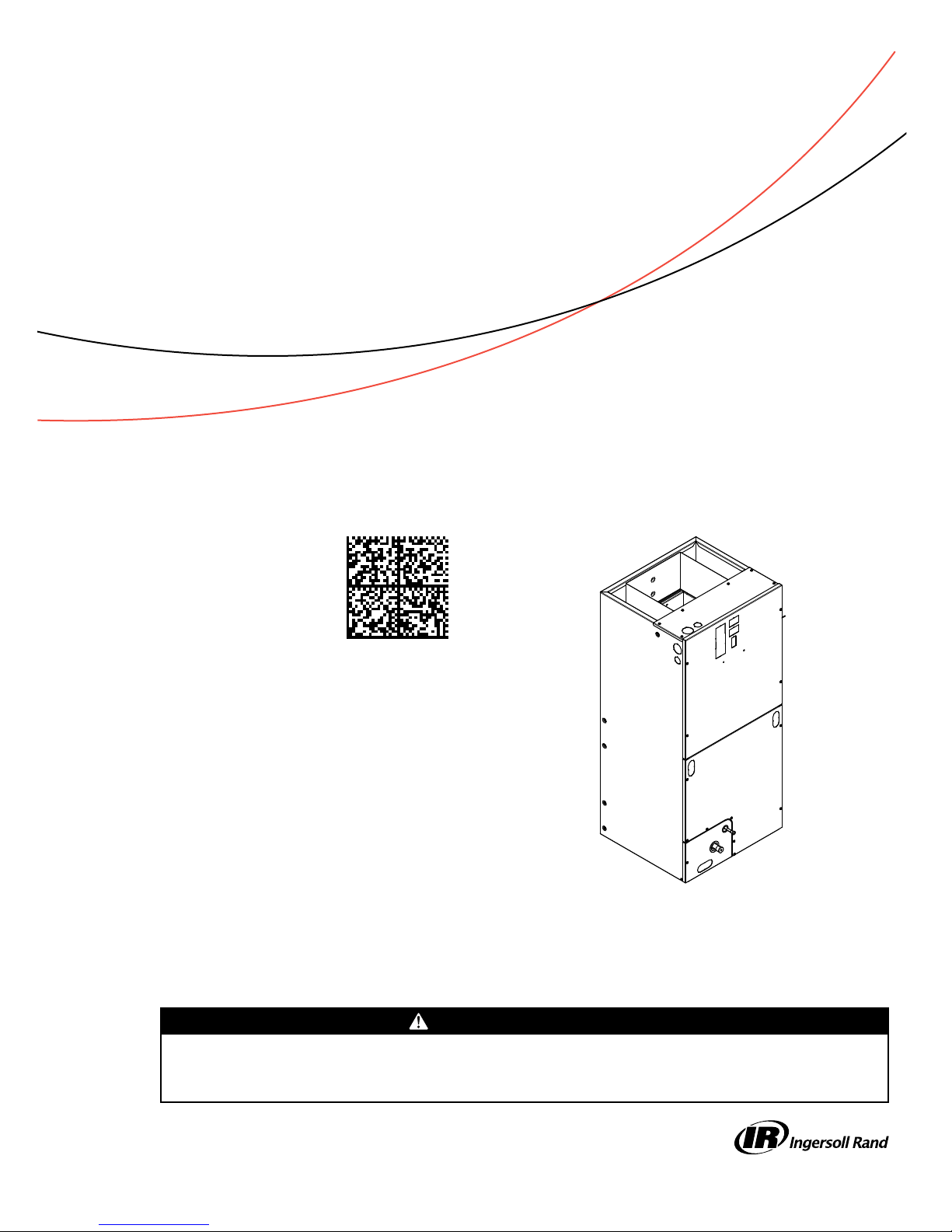
Installer’s Guide
Convertible Air Handlers
2 — 5 Ton
TEM6A0B24H21S
TEM6A0B30H21S
TEM6A0C36H31S
TEM6A0C42H41S
TEM6A0C48H41S
TEM6A0D48H41S
TEM6A0C60H51S
TEM6A0D60H51S
Only qualified personnel should install and service the equipment. The installation, starting up, and servicing of heating, ventilating, and
air-conditioning equipment can be hazardous and requires specific knowledge and training. Improperly installed, adjusted or altered
equipment by an unqualified person could result in death or serious injury. When working on the equipment, observe all precautions in the
literature and on the tags, stickers, and labels that are attached to the equipment.
January 2016
The TEM6 series air handler is designed for installation in a closet,
utility room, alcove, basement, crawlspace or attic. These versatile
units are applicable to air conditioning and heat pump
applications. Several models are available to meet the specific
requirements of the outdoor equipment. Field installed electric
resistance heaters are available.
SSAAFFEETTYY WWAARRNNIINNGG
18-GF74D1-1F-EN
Page 2
SAFETY SECTION
AIR HANDLERS
IImmppoorrttaanntt:: This document contains a wiring diagram,
a parts list, and service information. This is
customer property and is to remain with
this unit. Please return to service
information pack upon completion of work.
IImmppoorrttaanntt:: These instructions do not cover all
variations in systems nor provide for every
possible contingency to be met in
connection with the installation. Should
further information be desired or should
particular problems arise which are not
covered sufficiently for the purchaser’s
purposes, the matter should be referred to
your installing dealer or local distributor.
WWAARRNNIINNGG
HHAAZZAARRDDOOUUSS VVOOLLTTAAGGEE!!
FFaaiilluurree ttoo ffoollllooww tthhiiss WWaarrnniinngg ccoouulldd rreessuulltt iinn
pprrooppeerrttyy ddaammaaggee,, sseevveerree ppeerrssoonnaall iinnjjuurryy,, oorr ddeeaatthh..
DDiissccoonnnneecctt aallll eelleeccttrriicc ppoowweerr,, iinncclluuddiinngg rreemmoottee
ddiissccoonnnneeccttss bbeeffoorree sseerrvviicciinngg.. FFoollllooww pprrooppeerr
lloocckkoouutt//ttaaggoouutt pprroocceedduurreess ttoo eennssuurree tthhee ppoowweerr
ccaannnnoott bbee iinnaaddvveerrtteennttllyy eenneerrggiizzeedd..
CCAAUUTTIIOONN
GGRROOUUNNDDIINNGG RREEQQUUIIRREEDD!!
FFaaiilluurree ttoo iinnssppeecctt oorr uussee pprrooppeerr sseerrvviiccee ttoooollss mmaayy
rreessuulltt iinn eeqquuiippmmeenntt ddaammaaggee oorr ppeerrssoonnaall iinnjjuurryy..
RReeccoonnnneecctt aallll ggrroouunnddiinngg ddeevviicceess.. AAllll ppaarrttss ooff tthhiiss
pprroodduucctt tthhaatt aarree ccaappaabbllee ooff ccoonndduuccttiinngg eelleeccttrriiccaall
ccuurrrreenntt aarree ggrroouunnddeedd.. IIff ggrroouunnddiinngg wwiirreess,, ssccrreewwss,,
ssttrraappss,, cclliippss,, nnuuttss,, oorr wwaasshheerrss uusseedd ttoo ccoommpplleettee aa
ppaatthh ttoo ggrroouunndd aarree rreemmoovveedd ffoorr sseerrvviiccee,, tthheeyy mmuusstt
bbee rreettuurrnneedd ttoo tthheeiirr oorriiggiinnaall ppoossiittiioonn aanndd pprrooppeerrllyy
ffaasstteenneedd..
WWAARRNNIINNGG
LLIIVVEE EELLEECCTTRRIICCAALL CCOOMMPPOONNEENNTTSS!!
FFaaiilluurree ttoo ffoollllooww tthhiiss WWaarrnniinngg ccoouulldd rreessuulltt iinn
pprrooppeerrttyy ddaammaaggee,, sseevveerree ppeerrssoonnaall iinnjjuurryy,, oorr ddeeaatthh..
FFoollllooww aallll eelleeccttrriiccaall ssaaffeettyy pprreeccaauuttiioonnss wwhheenn
eexxppoosseedd ttoo lliivvee eelleeccttrriiccaall ccoommppoonneennttss.. IItt mmaayy bbee
nneecceessssaarryy ttoo wwoorrkk wwiitthh lliivvee eelleeccttrriiccaall ccoommppoonneennttss
dduurriinngg iinnssttaallllaattiioonn,, tteessttiinngg,, sseerrvviicciinngg,, aanndd
ttrroouubblleesshhoooottiinngg ooff tthhiiss pprroodduucctt..
WWAARRNNIINNGG
PPRREESSSSUURRIIZZEEDD RREEFFRRIIGGEERRAANNTT!!
FFaaiilluurree ttoo ffoollllooww tthhiiss WWaarrnniinngg ccoouulldd rreessuulltt iinn
ppeerrssoonnaall iinnjjuurryy
SSyysstteemm ccoonnttaaiinnss ooiill aanndd rreeffrriiggeerraanntt uunnddeerr hhiigghh
pprreessssuurree.. RReeccoovveerr rreeffrriiggeerraanntt ttoo rreelliieevvee pprreessssuurree
bbeeffoorree ooppeenniinngg tthhee ssyysstteemm.. DDoo nnoo uussee nnoonn-aapppprroovveedd rreeffrriiggeerraannttss oorr rreeffrriiggeerraanntt ssuubbssttiittuutteess oorr
rreeffrriiggeerraanntt aaddddiittiivveess..
CCAAUUTTIIOONN
SSHHAARRPP EEDDGGEE HHAAZZAARRDD!!
FFaaiilluurree ttoo ffoollllooww tthhiiss CCaauuttiioonn ccoouulldd rreessuulltt iinn
pprrooppeerrttyy ddaammaaggee oorr ppeerrssoonnaall iinnjjuurryy..
BBee ccaarreeffuull ooff sshhaarrpp eeddggeess oonn eeqquuiippmmeenntt oorr aannyy
ccuuttss mmaaddee oonn sshheeeett mmeettaall wwhhiillee iinnssttaalllliinngg oorr
sseerrvviicciinngg..
CCAAUUTTIIOONN
HHAAZZAARRDDOOUUSS VVAAPPOORRSS!!
FFaaiilluurree ttoo ffoollllooww tthhiiss ccaauuttiioonn ccoouulldd rreessuulltt iinn
pprrooppeerrttyy ddaammaaggee oorr ppeerrssoonnaall iinnjjuurryy..
EEqquuiippmmeenntt ccoorrrroossiioonn ddaammaaggee.. TToo pprreevveenntt
sshhoorrtteenniinngg iittss sseerrvviiccee lliiffee,, tthhee aaiirr hhaannddlleerr sshhoouulldd
nnoott bbee uusseedd dduurriinngg tthhee ffiinniisshhiinngg pphhaasseess ooff
ccoonnssttrruuccttiioonn oorr rreemmooddeelliinngg.. TThhee llooww rreettuurrnn aaiirr
tteemmppeerraattuurreess ccaann lleeaadd ttoo tthhee ffoorrmmaattiioonn ooff
ccoonnddeennssaattee.. CCoonnddeennssaattee iinn tthhee pprreesseennccee ooff
cchhlloorriiddeess aanndd fflluuoorriiddeess ffrroomm ppaaiinntt,, vvaarrnniisshh,, ssttaaiinnss,,
aaddhheessiivveess,, cclleeaanniinngg ccoommppoouunnddss,, aanndd cceemmeenntt
ccrreeaatteess aa ccoorrrroossiivvee ccoonnddiittiioonn wwhhiicchh mmaayy ccaauussee
rraappiidd ddeetteerriioorraattiioonn ooff tthhee ccaabbiinneett aanndd iinntteerrnnaall
ccoommppoonneennttss..
CCAAUUTTIIOONN
CCOOIILL IISS PPRREESSSSUURRIIZZEEDD!!
•• CCooiill iiss pprreessssuurriizzeedd wwiitthh aapppprrooxxiimmaatteellyy 88––1122 ppssii
ddrryy aaiirr aanndd ffaaccttoorryy cchheecckkeedd ffoorr lleeaakkss..
•• CCaarreeffuullllyy rreelleeaassee tthhee pprreessssuurree bbyy rreemmoovviinngg tthhee
rruubbbbeerr pplluugg oonn tthhee lliiqquuiidd lliinnee..
•• IIff nnoo pprreessssuurree iiss rreelleeaasseedd,, cchheecckk ffoorr lleeaakkss..
©2016 Trane
18-GF74D1-1F-EN
Page 3

SSAAFFEETTYY SSEECCTTIIOONN AAIIRR HHAANNDDLLEERRSS
WWAARRNNIINNGG
SSAAFFEETTYY HHAAZZAARRDD!!
FFiibbeerrggllaassss dduusstt aanndd cceerraammiicc ffiibbeerrss aarree bbeelliieevveedd bbyy
tthhee ssttaattee ooff CCaalliiffoorrnniiaa ttoo ccaauussee ccaanncceerr tthhrroouugghh
iinnhhaallaattiioonn.. GGllaasssswwooooll ffiibbeerrss mmaayy aallssoo ccaauussee
rreessppiirraattoorryy,, sskkiinn,, oorr eeyyee iirrrriittaattiioonn..
PPRREECCAAUUTTIIOONNAARRYY MMEEAASSUURREESS
•• AAvvooiidd bbrreeaatthhiinngg ffiibbeerrggllaassss dduusstt
•• UUssee aa NNIIOOSSHH aapppprroovveedd dduusstt//mmiisstt rreessppiirraattoorr
•• AAvvooiidd ccoonnttaacctt wwiitthh tthhee sskkiinn oorr eeyyeess.. WWeeaarr lloonngg-sslleeeevveedd,, lloooossee ffiittttiinngg ccllootthhiinngg,, gglloovveess,, aanndd eeyyee
pprrootteeccttiioonn
•• WWaasshh ccllootthheess sseeppaarraatteellyy ffrroomm ootthheerr ccllootthhiinngg,,
rriinnssee wwaasshheerr tthhoorroouugghhllyy
•• OOppeerraattiioonnss ssuucchh aass ssaawwiinngg,, bblloowwiinngg,, tteeaarr--oouutt,,
aanndd sspprraayyiinngg mmaayy ggeenneerraattee ffiibbeerr ccoonncceennttrraattiioonnss
rreeqquuiirriinngg aaddddiittiioonnaall rreessppiirraattoorryy pprrootteeccttiioonn.. UUssee
tthhee aapppprroopprriiaattee NNIIOOSSHH aapppprroovveedd rreessppiirraattoorr iinn
tthheessee ssiittuuaattiioonnss
FFIIRRSSTT AAIIDD MMEEAASSUURREESS
•• EEYYEE CCOONNTTAACCTT:: FFLLUUSSHH EEYYEESS WWIITTHH WWAATTEERR TTOO
RREEMMOOVVEE DDUUSSTT.. IIFF SSYYMMPPTTOOMMSS PPEERRSSIISSTT,, SSEEEEKK
MMEEDDIICCAALL AATTTTEENNTTIIOONN..
•• SSKKIINN CCOONNTTAACCTT:: WWAASSHH AAFFFFEECCTTEEDD AARREEAA
GGEENNTTLLYY WWIITTHH SSOOAAPP AANNDD WWAARRMM WWAATTEERR AAFFTTEERR
HHAANNDDLLIINNGG..
TThhiiss wwaarrnniinngg ccoommpplliieess wwiitthh ssttaattee ooff CCaalliiffoorrnniiaa llaaww,,
PPrrooppoossiittiioonn 6655..
NNoottee:: Air handlers have been evaluated in accordance
with the Code of Federal Regulations, Chapter
XX, Part 3280 or the equivalent.“SUITABLE FOR
MOBILE HOME USE.”
NNoottee:: Condensation may occur on the surface of the air
handler when installed in an unconditioned
space. When units are installed in unconditioned
spaces, verify that all electrical and refrigerant
line penetrations on the air handler are sealed
completely.
NNoottee:: The manufacturer recommends installing ONLY
A.H.R.I approved, matched indoor and outdoor
systems. Some of the benefits of installing
approved matched indoor and outdoor split
systems are maximum efficiency, optimum
performance, and the best overall system
reliability.
WWAARRNNIINNGG
SSAAFFEETTYY HHAAZZAARRDD!!
TThhiiss aapppplliiaannccee iiss nnoott ttoo bbee uusseedd bbyy ppeerrssoonnss
((iinncclluuddiinngg cchhiillddrreenn)) wwiitthh rreedduucceedd pphhyyssiiccaall,,
sseennssoorryy,, oorr mmeennttaall ccaappaabbiilliittiieess,, oorr llaacckk ooff
eexxppeerriieennccee aanndd kknnoowwlleeddggee,, uunnlleessss tthheeyy hhaavvee bbeeeenn
ggiivveenn ssuuppeerrvviissiioonn oorr iinnssttrruuccttiioonn..
WWAARRNNIINNGG
SSAAFFEETTYY HHAAZZAARRDD!!
CChhiillddrreenn sshhoouulldd bbee ssuuppeerrvviisseedd ttoo eennssuurree tthhaatt tthheeyy
ddoo nnoott ppllaayy wwiitthh tthhee aapppplliiaannccee..
IImmppoorrttaanntt:: Installation of this unit shall be made in
accordance with the National Electric Code,
NFPA No. 90A and 90B, and any other local
codes or utilities requirements.
IImmppoorrttaanntt:: Air handlers do not require repositioning of
the coil or drain pan for upflow or
horizontal left applications. See the
downflow and horizontal right installation
sections for application instructions.
18-GF74D1-1F-EN
3
Page 4

Table of Contents
Features . . . . . . . . . . . . . . . . . . . . . . . . . . . . . . . . . . . . 5
Installation Instructions . . . . . . . . . . . . . . . . . . . 5
Field Wiring . . . . . . . . . . . . . . . . . . . . . . . . . . . . . . . . 9
Electrical Data . . .. . . . . . . . . . . . . . . . . . . . . . . . . . 11
Performance and Electrical Data . . . . . . . . . . . 12
Minimum Airflow CFM . . . . . . . . . . . . . . . . . . . . 19
Outline Drawing . . . . . . . . . . . . . . . . . . . . . . . . . . . 21
Heater Pressure Drop Table . . . . . . . . . . . . . . . . 22
Subcooling Adjustment . . . . . . . . . . . . . . . . . . 22
Subcooling Adjustment for
TEM6A0C48H41 & TEM6A0C60H51 . . . . . . . 22
Coil Conversion Instructions. . . . . . . . . . . . . . . 23
Coil Conversion . . . . . . . . . . . . . . . . . . . . . . . . . 28
Checkout Procedures . . . . . . . . . . . . . . . . . . . . . . 36
4
18-GF74D1-1F-EN
Page 5

Features
Table 1. Standard Features
• MULTI-POSITION UPFLOW, DOWNFLOW, HORIZONTAL LEFT
AND HORIZONTAL RIGHT
• PAINTED FINISH ON GALVANIZED STEEL EXTERIOR WITH
FULLY INSULATED CABINET THAT MEETS R4.2 VALUE
• STURDY POLYCARBONATE DRAIN PANS
– The TEM air handler has factory installed drain pans and
is shipped for upflow and horizontal left applications
• 208/230 VAC OPERATION
• VARIABLE-SPEED DIRECT DRIVE BLOWER.
• FACTORY INSTALLED R-410A THERMAL EXPANSION VALVE
• ALL ALUMINUM COIL
• BOTTOM RETURN
• MEETS THE MINIMUM LEAKAGE REQUIREMENTS FOR THE
FLORIDA AND CALIFORNIA BUILDING CODES
Table 2. Optional Accessories
• 4,5,8,10,15,20, and 25 KW SINGLE PHASE ELECTRIC
HEATERS
– Circuit breakers available on single phase 4, 5, 8, 10,
15, 20, and 25 KW heaters
– Lugs available on single phase 4, 5, 8, and 10 KW
heaters
– Lugs available on three phase 10 and 15 KW heaters
• SINGLE POINT POWER ENTRY KIT (for 15 and 20 KW
heaters)
• SUPPLY DUCT FLANGE KIT
• DOWNFLOW SUB-BASE KITS - TAYBASE185, TAYBASE235,
TAYBASE260
• SLIM FIT FILTER BOX KIT — BAYSF1185AAA,
BAYSF1235AAA, BAYSF1265AAA
Installation Instructions
1. UUnnppaacckkiinngg
Carefully unpack the unit and inspect the contents
for damage. If any damage is found at the time of
delivery, proper notification and claims should be
made with the carrier.
Check the rating plate to assure model number and
voltage, plus any kits match with what you ordered.
The manufacturer should be notified within 5 days
of any discrepancy or parts shortage.
2. LLooccaattiioonn
The air handler should be centrally located and may
be installed in a closet, alcove, utility room,
basement, crawl space or attic. Minimum
clearances must be met.
IIMMPPOORRTTAANNTT:: The downflow sub-base may be
required with electric heat applications.
See minimum clearance table.
The unit must be installed in a level position to
ensure proper condensation drainage. Make sure
the unit is level in both directions within 1/8" on
either side.
When the unit is installed in a closet or utility room,
the room should be large enough, and have an
opening to allow replacement of the unit. All
servicing is done from the front and a clearance of
21" is needed for service unless the closet door
aligns with the front of the air handler.
If you are installing the unit in an unconditioned
space such as an attic or crawl space, you must
ensure that the area provides sufficient air
circulation to prevent moisture collection on the
cabinet during high dew point conditions. A drain
pan must be installed under the entire unit when it
is installed in or above a finished ceiling or in an
unconditioned space.
3. DDuucctt WWoorrkk
The duct work should be installed in accordance
with the NFPA No. 90A "Installation of Air
Conditioning and Ventilating systems" and No. 90B
"Residential Type Warm Air Heating and Air
Conditioning Installation."
The duct work should be insulated in accordance
with the applicable requirements for the particular
installation as required by HUD, FHA, VA the
applicable building code, local utility or other
governing body.
4. CCoonnddeennssaattee DDrraaiinn
The unit is supplied with primary and auxiliary
condensate drains that have 3/4" NPT connections.
The primary drain must be trapped outside the unit
and piped in accordance with applicable building
codes. Do not reduce the drain line size less than
the connection size on the drain pan. Condensate
should be piped to an open drain or to the outside.
All drains must pitch downward away from the unit
a minimum of 1/4" per foot of line to ensure proper
drainage.
IIMMPPOORRTTAANNTT:: If cleanout Tee is used, stand pipe
must be sealed/capped.
Insulate the primary drain line to prevent sweating
where dew point temperatures may be met.
(Insulation is optional depending on climate and
application needs.)
18-GF74D1-1F-EN
5
Page 6
CFM
SELECTION
LIGHT
DIP
SWITCHES
DIP SWITCHES (TYPICAL SETTINGS)
COOLING
HEATING
AIRFLOW
FAN OFF
DELAY
AUXILARY
HEAT SPEEDS
OFF OFF
50%
80%
100% if necessary
50%
Dehumidify
Warm Air Heating
Fast Coil Cooling
Fast Coil Heating
Efficiency
7.5
minutes
3
minutes
1
minute
FAN OPERATION (CFM)
as required
COMPRESSOR OPERATION ON
OFF
FFeeaattuurreess
5. RReeffrriiggeerraanntt PPiippiinngg
Refrigerant piping external to the unit shall be sized
in accordance with the instructions of the
manufacturer of the outdoor equipment.
6. MMeetteerriinngg DDeevviiccee
All units are shipped and installed with an
internally-checked, non-bleed TXV designed for air
conditioning or heat pump operation. Some
outdoor models may require a start assist kit. See
outdoor unit for more information.
7. BBlloowweerr
This unit is supplied with a variable speed motor
with a direct drive blower wheel which can obtain
various air flows. The unit is shipped with factory
set cooling and heating air flows. Performance
tables are available for additional airflow settings.
Disconnect all power to the unit before making any
adjustments to the airflow settings. Be sure to check
the air flow and the temperature drop across the
evaporator coil to ensure sufficient air flow.
8. AAiirrffllooww AAddjjuussttmmeenntt
CCAAUUTTIIOONN
EEQQUUIIPPMMEENNTT DDAAMMAAGGEE!!
FFaaiilluurree ttoo ffoollllooww tthhiiss pprroocceedduurree mmaayy rreessuulltt iinn
eeqquuiippmmeenntt ddaammaaggee..
DDiissccoonnnneecctt ppoowweerr ttoo tthhee aaiirr hhaannddlleerr bbeeffoorree
cchhaannggiinngg ddiipp sswwiittcchh ppoossiittiioonnss..
Blower speed changes are made on the ECM Fan
Control. The ECM Fan Control controls the variable
speed motor.
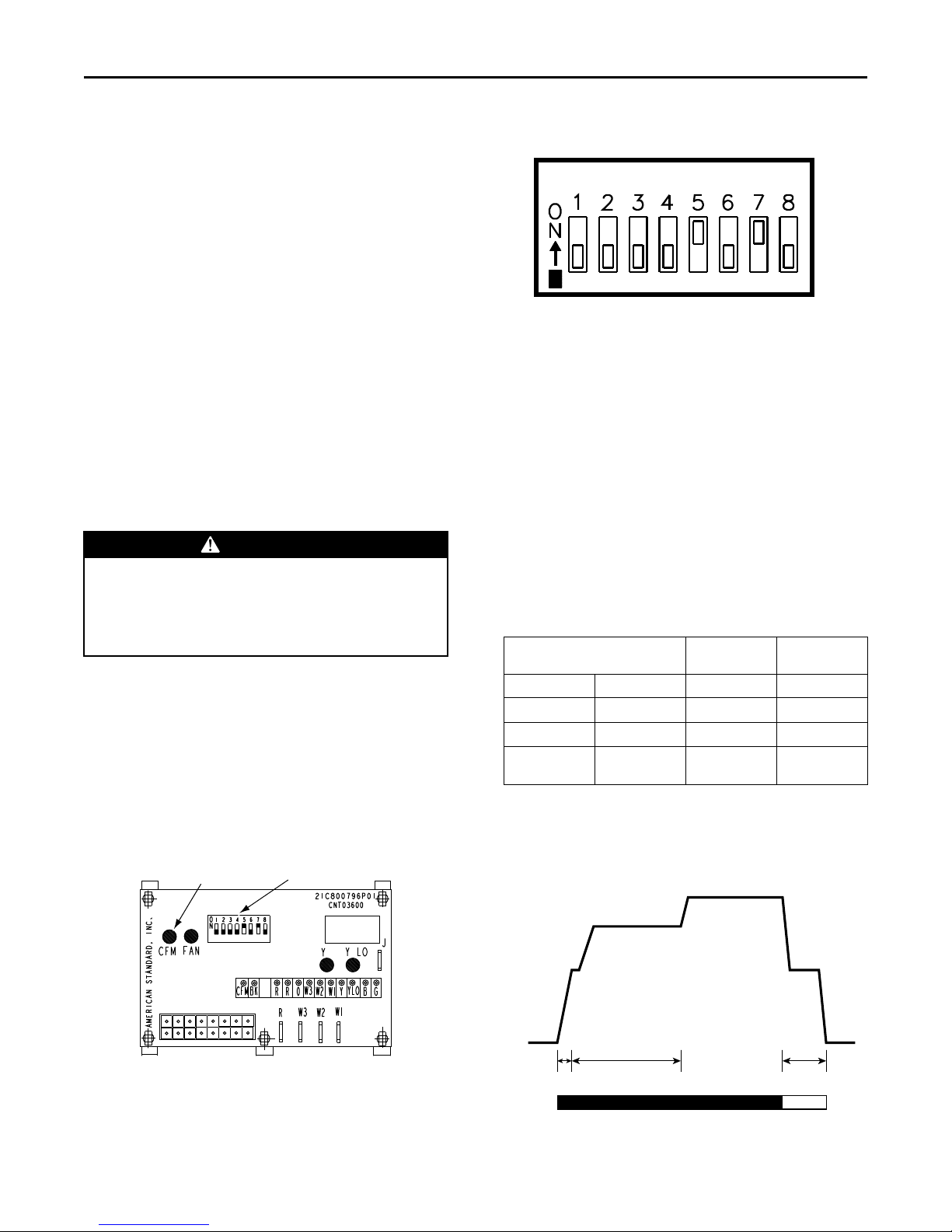
There is a bank of 8 dip switches. The dip switches
work in pairs to match the airflow for the outdoor
unit size (tons). cooling airflow adjustment, Fan offdelay options, and heating airflow adjustment. The
switches appear as shown in Figure 2, p. 6
Figure 1. ECM Fan Control
Figure 2. Dip Switches
If the airflow needs to be increased or decreased,
see the Airflow Label on the air handler or Blower
Performance Table.
Be sure to set the correct airflow for cooling and
heating.
Switches 1–4 Cooling Airflow
Switches 5–6 Fan Off Delay Options
Switches 7–8 Auxiliary Heat
IInnddoooorr BBlloowweerr TTiimmiinngg
IIMMPPOORRTTAANNTT:: Leave dip switches 5 and 6 in the “as-
shipped” positions during system startup and check out. Afterwards, adjust as
desired.
Table 3. Cooling Off — Delay Options
SWITCH SETTINGS SELECTION NOMINAL
5 — OFF 6 — OFF NONE SAME
5 — ON 6 — OFF 1.5 MINUTES 100%
5 — OFF 6 — ON 3 MINUTES 50%
5 — ON 6 — ON ENHANCED
(a)
Default setting
(b)
This ENHANCED MODE selection provides a ramping up and ramping
down of the blower speed to provide improved comfort, quietness,
and potential energy savings. The graph shows the ramping process.
(b)
AIRFLOW
50–100%
(a)
6
Figure 3. Enhanced Mode
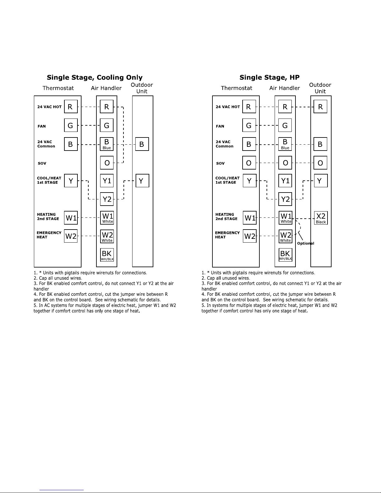
9. WWiirriinngg
18-GF74D1-1F-EN
Page 7

FFeeaattuurreess
Consult all schematic and pictorial wiring diagrams
of this unit and the outdoor equipment to determine
compatibility of wiring connections and to
determine specific requirements.
All field wiring to the air handler should be installed
in accordance with the latest edition of the National
Electric Code NFPA No. 70 and any local codes.
Check rating plates on unit for rated volts, minimum
circuit ampacity and maximum over current
protection. Supply circuit power wiring must be 75
degree C (167 degree F) minimum copper
conductors only. Copper supply wires shall be sized
to the National Electric Code or local code
requirements, whichever is more stringent.
The unit is shipped wired for 230/240 Volt AC 60 HZ
1 Phase Operation. If the unit is to be operated at
208 VAC 60HZ, follow the instructions on the indoor
unit wiring diagram to change the low voltage
transformer to 208 VAC operation (Ensure unit is
properly grounded).
Class 2 low voltage control wiring should not be run
in conduit with power wiring and must be
separated from power wiring unless class 1 wire
with proper voltage rating is used.
Low voltage control wiring should be 18 Awg, color
coded (105 degree C minimum). For lengths longer
than 100ft., 16 Awg wire should be used. Make
certain that separation of control wiring and power
wiring has been maintained.
10. AAiirr FFiilltteerr
To protect the coil, blower and other internal parts
from excessive dirt and dust an air filter must be
installed before air enters the evaporator coil. A
remote filter must be installed. Consult the filter
manufacturer for proper sizing and maximum
velocity requirements.
IImmppoorrttaanntt:: Air filters shall meet the test requirements
in UL 900.
11. TThheerrmmoossttaatt
Select a thermostat that is commonly used with HP
or AC single stage heating/cooling with electric
heat. The thermostat will energize the fan on a
demand for heat or cool.
Install the thermostat on an inside wall, away from
drafts, lights or other heat sources in a location that
has sufficient air circulation from other rooms being
controlled by the thermostat.
12. SSeeqquueennccee ooff OOppeerraattiioonn
CCoooolliinngg ((CCoooolliinngg oonnllyy))
When the thermostat calls for cooling, the circuit
from R to G is completed. The blower motor is
energized directly by the ECM fan control, which
receives the 24VAC signal from the thermostat.
The circuit from R to Y is also complete energizing
the compressor contactor of the outdoor unit. The
contactor will close and start the compressor and
condenser fan motor.
CCoooolliinngg ((hheeaatt ppuummpp))
When the thermostat calls for cooling, the circuit
from R to G is completed. The blower motor is
energized directly by the ECM fan control, which
receives the 24VAC signal from the thermostat.
The circuit from R to Y is also complete energizing
the compressor contactor of the outdoor unit. The
contactor will close and start the compressor and
condenser fan motor.
Circuit R to O energizes the reversing valve to the
cooling position.
HHeeaattiinngg ((hheeaatt ppuummpp))
When the thermostat calls for heating, the circuit
from R to G is completed and the blower motor is
energized directly by the ECM fan control, which
receives the 24VAC signal from the thermostat.
The circuit from R to Y is also complete energizing
the compressor contactor of the outdoor unit. The
contactor will close and start the compressor and
condenser fan motor.
18-GF74D1-1F-EN
7
Page 8

FFeeaattuurreess
In the heating mode, the reversing valve of the
outdoor unit is not energized.
If the indoor temperature continues to fall, the R to
W circuit is completed energizing the electric heat
contactor(s).
HHeeaattiinngg ((eelleeccttrriicc hheeaatt oonnllyy))
NNoottee:: The thermostat must be setup to bring the
blower on when the electric heat is energized.
When the thermostat calls for heating, the circuit
from R to G is completed and the blower motor is
energized directly by the ECM fan control, which
receives the 24VAC signal from the thermostat. The
circuit from R to W is completed energizing the
heating contactor(s).
DDeeffrroosstt
Supplemental heat during defrost can be provided
by connecting the X2 (black) wire from the outdoor
unit to W1 or W2 at the indoor unit. This will
prevent cold air from being discharged from the
indoor unit during defrost.
13. OOppeerraattiioonnaall aanndd CChheecckkoouutt PPrroocceedduurreess
To obtain proper performance, all units must be
operated and charge adjustments made in
accordance with procedures found in the Service
Facts document of the outdoor unit. After
installation has been completed, it is recommended
that the entire system be checked against the
checkout list located at the back of this document.
See “Checkout Procedures,” p. 36
14. MMaaiinntteennaannccee
The system air filter(s) should be inspected, cleaned
or replaced at least monthly. Make certain that the
access panels are replaced and secured properly
before placing the unit back in operation. This
product is designed for dependable service;
however, periodic maintenance should be
scheduled and conducted by trained professional
service personnel. This service should be
conducted at least annually, and should include
testing and inspection of electrical and refrigerant
components. The heat transfer surface should be
cleaned. The blower motor is permanently
lubricated for normal operating conditions.
8
18-GF74D1-1F-EN
Page 9
Field Wiring
Sing le St age, C o o lin g On ly
The rm ostat Air H andler
Outdoor
Unit
R
G
B
W1
W2
B
Y
R
G
B
Y
W1
Blue
24 VAC HOT
FAN
24 VAC
Common
SOV
COOL/HEAT
1st STAGE
HEATING
2nd STAGE
EMERGENCY
HEAT
White
White
W2
O
Y1
1. * Uni ts wi th pi gtai ls re quire wirenut s for conn ections.
2. Cap al l unu sed wire s.
3. F or BK ena b led com fort control, do not conn e ct Y1 or Y2 at the air
handl e r
Y2
BK
WH/BLK
4. F or BK ena b led com fort control, cut the jumpe r wire betw een R
and BK on the control board. See wi ring schematic for d e tails.
5. In AC s yst em s for mult iple s tages of e lectric heat , jumper W1 a n d W2
tog ether if c o m fort control h as o nly one sta g e of heat.
Sing le St age, HP
The rm ostat Air H andler
Outdoor
Unit
R
G
B
W1
W2
R
B
O
Y
X2
R
G
B
O
Y
W1
Blue
24 VAC HOT
FAN
24 VAC
Common
SOV
COOL/HEAT
1st STAGE
HEATING
2nd STAGE
EMERGENCY
HEAT
White
Black
White
W2
O
Y1
Y2
BK
Optional
WH/BLK
1. * Uni ts wi th pi gtai ls re quire wirenut s for conn ections.
2. Cap al l unu sed wire s.
3. F or BK ena b led com fort control, do not conn e ct Y1 or Y2 at the air
handl e r
4. F or BK ena b led com fort control, cut the jumpe r wire betw een R
and BK on the control board. See wi ring schematic for d e tails.
5. In s ystem s fo r m u ltiple stage s of electric he a t, jum per W1 a n d W2
tog ether if c o m fort control h as o nly one sta g e of heat.
18-GF74D1-1F-EN
9
Page 10
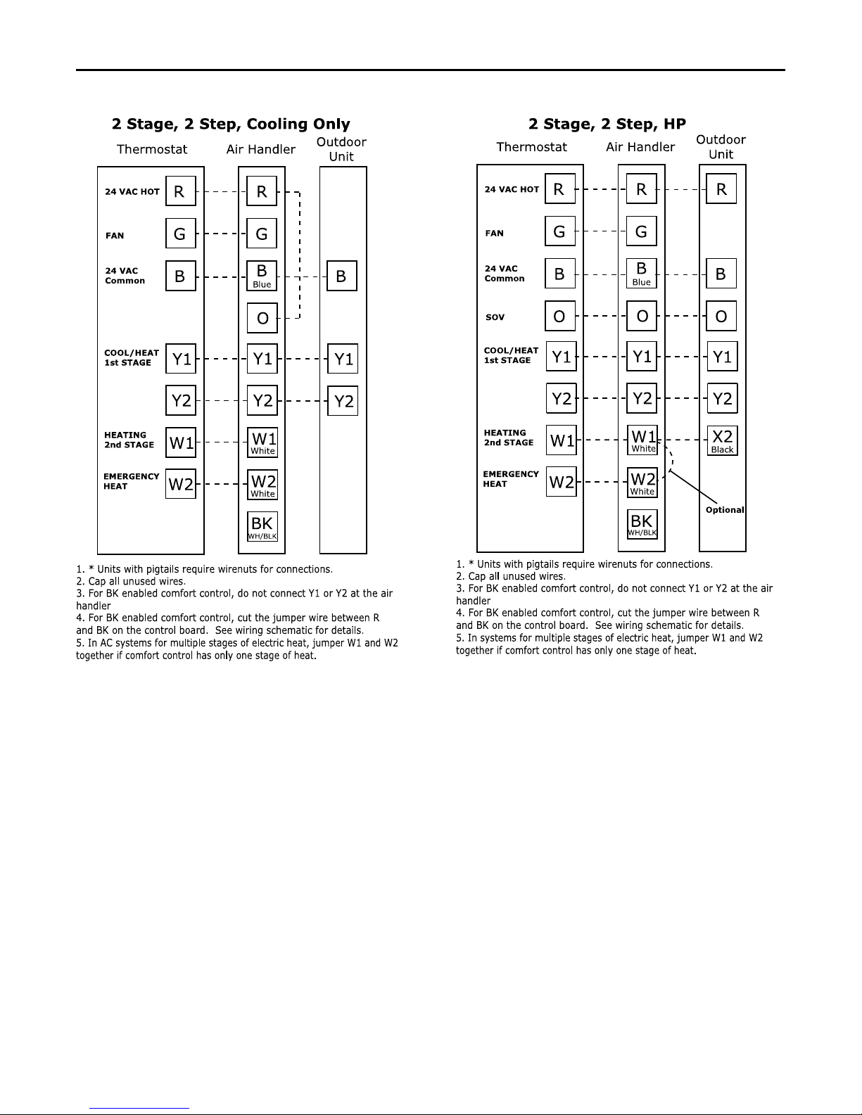
2 St age, 2 Step, Coo lin g O n ly
The rm o
stat
Air H andler
Outdoor
Unit
R
G
B
W1
W2
B
Y1
R
G
B
Y1
W1
Blue
24 VAC HOT
FAN
24 VAC
Common
COOL/HEAT
1st STAGE
HEATING
2nd STAGE
EMERGENCY
HEAT
White
White
W2
O
Y1
Y2
BK
Y2
Y2
WH/BLK
1. * Uni ts wi th pi gtai ls re quire wirenut s for conn ections.
2. Cap al l unu sed wire s.
3. F or BK ena b led com fort control, do not conn e ct Y1 or Y2 at the air
handl e r
4. F or BK ena b led com fort control, cut the jumpe r wire betw een R
and BK on the control board. See wi ring schematic for d e tails.
5. In AC s yst em s for mult iple s tages of e lectric heat , jumper W1 a n d W2
tog ether if c o m fort control h as o nly one sta g e of heat.
2 St age, 2 Step, HP
The rm ostat Air H andler
Outdoor
Unit
R
G
B
W1
W2
R
B
O
Y1
X2
R
G
B
O
Y1
W1
Blue
24 VAC HOT
FAN
24 VAC
Common
SOV
COOL/HEAT
1st STAGE
HEATING
2nd STAGE
EMERGENCY
HEAT
White
Black
White
W2
O
Y1
Y2
BK
Optional
Y2Y2
WH/BLK
1. * Uni ts wi th pi gtai ls re quire wirenut s for conn ections.
2. Cap al l unu sed wire s.
3. F or BK ena b led com fort control, do not conn e ct Y1 or Y2 at the air
handl e r
4. F or BK ena b led com fort control, cut the jumpe r wire betw een R
and BK on the control board. See wi ring schematic for d e tails.
5. In s ystem s fo r m u ltiple stage s of electric he a t, jum per W1 a n d W2
tog ether if c o m fort control h as o nly one sta g e of heat.
FFiieelldd WWiirriinngg
10
18-GF74D1-1F-EN
Page 11
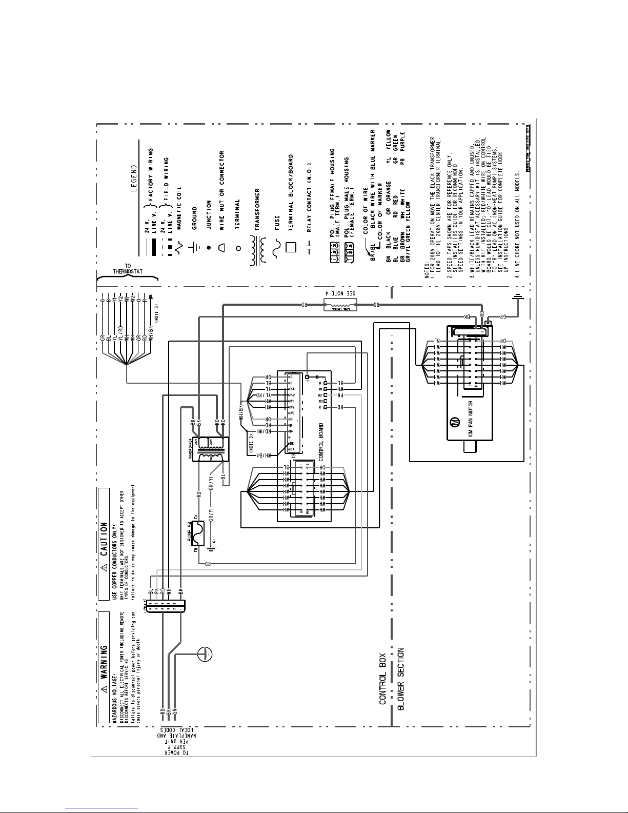
Electrical Data
18-GF74D1-1F-EN
11
Page 12
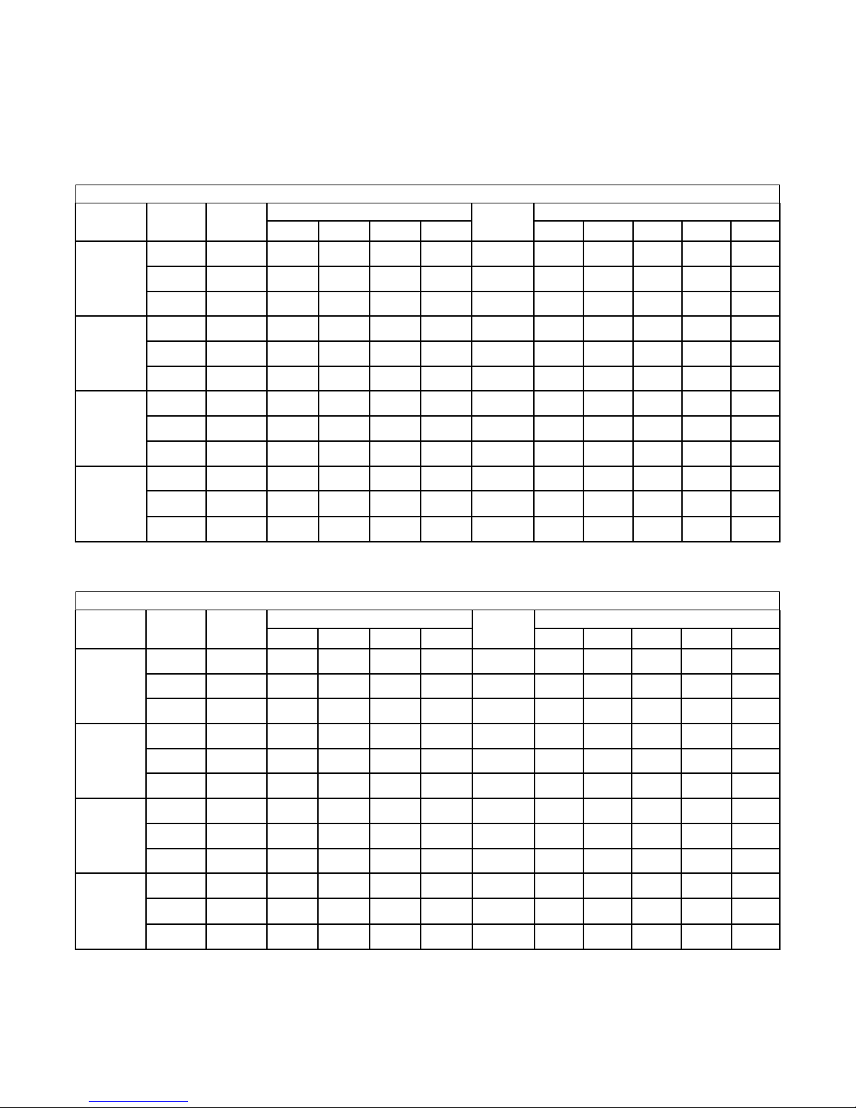
Performance and Electrical Data
Table 4. Air Flow Performance
TEM6A0B24, TEM6A0B30 COOLING AIRFLOW PERFORMANCE, WET COIL, NO FILTER, NO HEATER
OUTDOOR
UNIT SIZE
(TONS)
1.5
2
2.5
3
(a)
Factory Default Setting
SPEED
SETTING
LOW
NORMAL
HIGH
LOW
NORMAL
HIGH
LOW
NORMAL
HIGH
LOW
NORMAL
(a)
HIGH
AIRFLOW
SETTING
353 CFM/
ton
401 CFM/
ton
451 CFM/
ton
343 CFM/
ton
390 CFM/
ton
439 CFM/
ton
300 CFM/
ton
340 CFM/
ton
383 CFM/
ton
323 CFM/
ton
367 CFM/
ton
413 CFM/
ton
DIP SWITCH SETTING
SW1 SW2 SW3 SW4 0.1 0.3 0.5 0.7 0.9
ON ON OFF ON
ON ON OFF OFF
ON ON ON OFF
OFF ON OFF ON
OFF ON OFF OFF
OFF ON ON OFF
ON OFF OFF ON
ON OFF OFF OFF
ON OFF ON OFF
OFF OFF OFF ON
OFF OFF OFF OFF
OFF OFF ON OFF
AIRFLOW
POWER
CFM
Watts
CFM
Watts
CFM
Watts
CFM
Watts
CFM
Watts
CFM
Watts
CFM
Watts
CFM
Watts
CFM
Watts
CFM
Watts
CFM
Watts
CFM
Watts
EXTERNAL STATIC PRESSURE
533
52
611
65
684
81
687
82
789
104
884
135
752
92
859
128
963
172
959
169
1097
240
1192
304
497
78
580
95
668
115
672
115
798
145
887
177
749
123
861
172
973
223
962
217
1100
296
1150
331
461
104
548
125
644
148
648
149
780
183
882
230
729
167
863
211
995
263
974
263
1100
343
1115
354
425
130
517
155
611
182
614
182
735
216
845
274
691
211
830
242
967
291
940
297
1034
363
1031
361
390
157
486
185
570
215
571
215
663
246
751
290
636
241
727
268
844
308
816
311
858
341
856
339
Table 5. Air Flow Performance
TEM6A0B24, TEM6A0B30 HEATING AIRFLOW PERFORMANCE, NO FILTER, NO HEATER
OUTDOOR
UNIT SIZE
(TONS)
1.5
2
2.5
3
(a)
Factory Default Setting
SPEED
SETTING
LOW
NORMAL
HIGH
LOW
NORMAL
HIGH
LOW
NORMAL
HIGH
LOW
NORMAL
(a)
HIGH
AIRFLOW
SETTING
394 CFM/
ton
448 CFM/
ton
493 CFM/
ton
393 CFM/
ton
446 CFM/
ton
491 CFM/
ton
350 CFM/
ton
398 CFM/
ton
437 CFM/
ton
338 CFM/
ton
384 CFM/
ton
422 CFM/
ton
DIP SWITCH SETTING
SW1 SW2 SW3 SW4 0.1 0.3 0.5 0.7 0.9
ON ON OFF ON
ON ON OFF OFF
ON ON ON OFF
OFF ON OFF ON
OFF ON OFF OFF
OFF ON ON OFF
ON OFF OFF ON
ON OFF OFF OFF
ON OFF ON OFF
OFF OFF OFF ON
OFF OFF OFF OFF
OFF OFF ON OFF
AIRFLOW
POWER
CFM
Watts
CFM
Watts
CFM
Watts
CFM
Watts
CFM
Watts
CFM
Watts
CFM
Watts
CFM
Watts
CFM
Watts
CFM
Watts
CFM
Watts
CFM
Watts
EXTERNAL STATIC PRESSURE
599
58
680
72
748
89
785
97
904
131
980
167
866
125
995
171
1099
220
1010
174
1154
246
1245
305
571
88
665
109
746
118
790
128
902
179
972
216
870
162
988
222
1086
274
1001
224
1151
312
1167
322
539
117
641
145
682
163
773
175
912
219
990
268
866
215
1005
271
1098
328
1018
275
1135
350
1127
346
502
146
610
178
545
208
735
223
894
253
974
308
833
263
986
309
1065
362
1000
315
1066
361
1067
361
462
175
572
209
326
240
674
253
809
281
863
324
750
286
872
325
918
353
888
331
905
345
927
352
12
18-GF74D1-1F-EN
Page 13
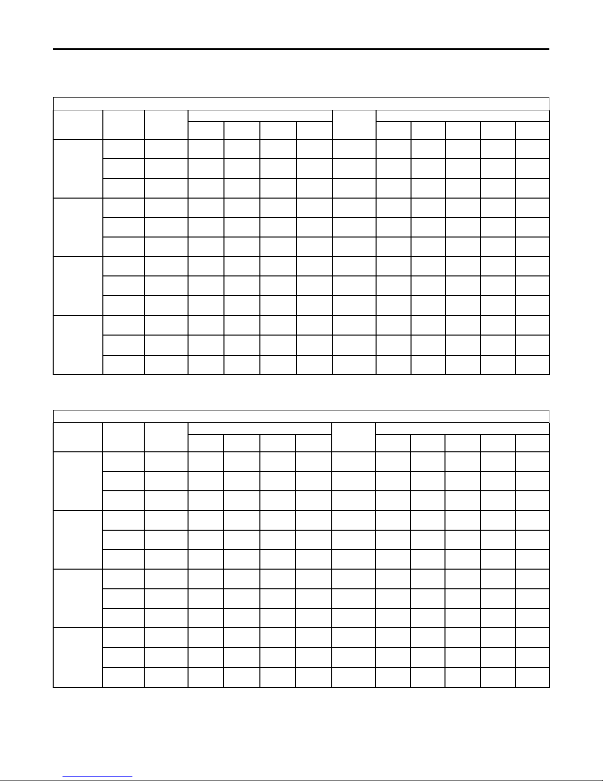
Table 6. Air Flow Performance
TEM6A0C36, TEM6A0C42 COOLING AIRFLOW PERFORMANCE, WET COIL, NO FILTER, NO HEATER
OUTDOOR
UNIT SIZE
(TONS)
2.5
3
3.5
4
(a)
Factory Default Setting
SPEED
SETTING
LOW
NORMAL
HIGH
LOW
NORMAL
HIGH
LOW
NORMAL
HIGH
LOW
NORMAL
(a)
HIGH
AIRFLOW
SETTING
300 CFM/
ton
341 CFM/
ton
384 CFM/
ton
319 CFM/
ton
363 CFM/
ton
408 CFM/
ton
315 CFM/
ton
357 CFM/
ton
402 CFM/
ton
308 CFM/
ton
350 CFM/
ton
394 CFM/
ton
PPeerrffoorrmmaannccee aanndd EElleeccttrriiccaall DDaattaa
DIP SWITCH SETTING
SW1 SW2 SW3 SW4 0.1 0.3 0.5 0.7 0.9
ON ON OFF ON
ON ON OFF OFF
ON ON ON OFF
OFF ON OFF ON
OFF ON OFF OFF
OFF ON ON OFF
ON OFF OFF ON
ON OFF OFF OFF
ON OFF ON OFF
OFF OFF OFF ON
OFF OFF OFF OFF
OFF OFF ON OFF
AIRFLOW
POWER
CFM
Watts
CFM
Watts
CFM
Watts
CFM
Watts
CFM
Watts
CFM
Watts
CFM
Watts
CFM
Watts
CFM
Watts
CFM
Watts
CFM
Watts
CFM
Watts
EXTERNAL STATIC PRESSURE
761
63
862
82
962
106
961
106
1092
146
1231
196
1104
150
1258
209
1418
286
1238
199
1412
282
1570
393
755
98
861
120
963
147
962
147
1093
192
1231
249
1105
197
1258
263
1415
347
1238
253
1410
344
1528
436
719
131
834
158
948
190
947
189
1082
240
1221
301
1094
245
1248
317
1401
406
1229
306
1398
404
1473
466
654
163
781
196
915
234
914
233
1060
288
1203
353
1072
293
1229
369
1379
462
1210
357
1378
462
1406
483
560
193
700
235
863
279
862
279
1026
337
1175
404
1039
343
1201
421
1348
516
1182
408
1349
517
1326
488
Table 7. Air Flow Performance
TEM6A0C36, TEM6A0C42 HEATING AIRFLOW PERFORMANCE, NO FILTER, NO HEATER
OUTDOOR
UNIT SIZE
(TONS)
2.5
3
3.5
4
(a)
Factory Default Setting
SPEED
SETTING
LOW
NORMAL
HIGH
LOW
NORMAL
HIGH
LOW
NORMAL
HIGH
LOW
NORMAL
(a)
HIGH
AIRFLOW
SETTING
341 CFM/
ton
379 CFM/
ton
417 CFM/
ton
381 CFM/
ton
424 CFM/
ton
466 CFM/
ton
348 CFM/
ton
386 CFM/
ton
425 CFM/
ton
338 CFM/
ton
375 CFM/
ton
413 CFM/
ton
DIP SWITCH SETTING
SW1 SW2 SW3 SW4 0.1 0.3 0.5 0.7 0.9
ON ON OFF ON
ON ON OFF OFF
ON ON ON OFF
OFF ON OFF ON
OFF ON OFF OFF
OFF ON ON OFF
ON OFF OFF ON
ON OFF OFF OFF
ON OFF ON OFF
OFF OFF OFF ON
OFF OFF OFF OFF
OFF OFF ON OFF
AIRFLOW
POWER
CFM
Watts
CFM
Watts
CFM
Watts
CFM
Watts
CFM
Watts
CFM
Watts
CFM
Watts
CFM
Watts
CFM
Watts
CFM
Watts
CFM
Watts
CFM
Watts
EXTERNAL STATIC PRESSURE
860
77
949
98
1042
122
1147
154
1277
204
1409
260
1222
180
1361
240
1497
316
1360
239
1511
325
1659
420
863
115
953
138
1046
166
1149
203
1279
259
1409
323
1224
232
1362
300
1478
372
1361
299
1489
380
1605
463
838
154
937
180
1036
212
1141
253
1272
314
1401
383
1216
285
1354
358
1449
420
1353
358
1456
426
1535
488
788
193
906
224
1015
259
1123
303
1255
368
1384
442
1200
336
1337
415
1408
461
1336
415
1412
464
1450
494
707
232
852
269
980
308
1094
353
1228
421
1357
500
1174
388
1310
471
1356
494
1309
470
1355
493
1349
483
18-GF74D1-1F-EN
13
Page 14
PPeerrffoorrmmaannccee aanndd EElleeccttrriiccaall DDaattaa
Table 8. Air Flow Performance
TEM6A0C48, TEM6A0C60 COOLING AIRFLOW PERFORMANCE, WET COIL, NO FILTER, NO HEATER
OUTDOOR
UNIT SIZE
(TONS)
3
3.5
4
5
(a)
Factory Default Setting
(b)
Airflow must not exceed 1800 cfm in horizontal right, horizontal left, and downflow applications due to condensate blowoff. The 5 ton high tap shall not be
used in these applications.
SPEED
SETTING
LOW
NORMAL
HIGH
LOW
NORMAL
HIGH
LOW
NORMAL
HIGH
LOW
NORMAL
(a)
(b)
HIGH
AIRFLOW
SETTING
324 CFM/
ton
368 CFM/
ton
423 CFM/
ton
314 CFM/
ton
357 CFM/
ton
411 CFM/
ton
298 CFM/
ton
339 CFM/
ton
389 CFM/
ton
305 CFM/
ton
347 CFM/
ton
399 CFM/
ton
DIP SWITCH SETTING
SW1 SW2 SW3 SW4 0.1 0.3 0.5 0.7 0.9
ON ON OFF ON
ON ON OFF OFF
ON ON ON OFF
OFF ON OFF ON
OFF ON OFF OFF
OFF ON ON OFF
ON OFF OFF ON
ON OFF OFF OFF
ON OFF ON OFF
OFF OFF OFF ON
OFF OFF OFF OFF
OFF OFF ON OFF
AIRFLOW
POWER
CFM
Watts
CFM
Watts
CFM
Watts
CFM
Watts
CFM
Watts
CFM
Watts
CFM
Watts
CFM
Watts
CFM
Watts
CFM
Watts
CFM
Watts
CFM
Watts
EXTERNAL STATIC PRESSURE
991
89
1120
118
1282
162
1116
117
1263
156
1449
218
1207
140
1368
190
1564
264
1534
251
1740
344
1995
484
985
133
1119
167
1286
219
1114
165
1266
212
1458
287
1208
193
1374
252
1577
343
1545
328
1758
444
2022
629
974
186
1110
224
1281
280
1105
222
1261
273
1456
352
1201
252
1370
315
1577
411
1545
394
1762
518
2030
717
984
237
1116
279
1280
343
1111
277
1261
334
1449
421
1203
311
1367
381
1567
484
1536
467
1745
594
2005
783
994
303
1122
333
1282
402
1117
331
1263
392
1447
496
1207
366
1367
448
1561
570
1531
550
1734
684
1987
828
Table 9. Air Flow Performance
TEM6A0C48, TEM6A0C60 HEATING AIRFLOW PERFORMANCE, NO FILTER, NO HEATER
OUTDOOR
UNIT SIZE
(TONS)
3
3.5
4
5
(a)
Factory Default Setting
SPEED
SETTING
LOW
NORMAL
HIGH
LOW
NORMAL
HIGH
LOW
NORMAL
HIGH
LOW
NORMAL
(a)
HIGH
AIRFLOW
SETTING
360 CFM/
ton
400 CFM/
ton
440 CFM/
ton
348 CFM/
ton
387 CFM/
ton
426 CFM/
ton
338 CFM/
ton
375 CFM/
ton
413 CFM/
ton
326 CFM/
ton
362 CFM/
ton
398 CFM/
ton
DIP SWITCH SETTING
SW1 SW2 SW3 SW4 0.1 0.3 0.5 0.7 0.9
ON ON OFF ON
ON ON OFF OFF
ON ON ON OFF
OFF ON OFF ON
OFF ON OFF OFF
OFF ON ON OFF
ON OFF OFF ON
ON OFF OFF OFF
ON OFF ON OFF
OFF OFF OFF ON
OFF OFF OFF OFF
OFF OFF ON OFF
AIRFLOW
POWER
CFM
Watts
CFM
Watts
CFM
Watts
CFM
Watts
CFM
Watts
CFM
Watts
CFM
Watts
CFM
Watts
CFM
Watts
CFM
Watts
CFM
Watts
CFM
Watts
EXTERNAL STATIC PRESSURE
1097
112
1215
142
1333
178
1232
147
1366
189
1500
238
1364
188
1509
241
1659
305
1637
295
1814
381
1990
481
1094
160
1216
196
1338
238
1234
202
1373
252
1511
311
1370
251
1520
315
1674
395
1652
383
1834
493
2017
625
1086
216
1210
255
1333
300
1228
261
1369
314
1510
377
1366
313
1519
382
1676
466
1653
453
1839
570
2025
713
1092
271
1211
314
1331
365
1229
322
1366
381
1502
449
1363
379
1511
453
1662
541
1641
528
1820
645
2000
779
1099
326
1215
369
1332
428
1233
377
1365
447
1498
529
1363
446
1506
535
1654
632
1632
618
1807
730
1982
826
14
18-GF74D1-1F-EN
Page 15
Table 10. Air Flow Performance
TEM6A0D48, TEM6A0D60 COOLING AIRFLOW PERFORMANCE, WET COIL, NO FILTER, NO HEATER
OUTDOOR
UNIT SIZE
(TONS)
3
3.5
4
5
(a)
Factory Default Setting
SPEED
SETTING
LOW
NORMAL
HIGH
LOW
NORMAL
HIGH
LOW
NORMAL
HIGH
LOW
NORMAL
(a)
HIGH
AIRFLOW
SETTING
323 CFM/
ton
367 CFM/
ton
415 CFM/
ton
315 CFM/
ton
358 CFM/
ton
404 CFM/
ton
309 CFM/
ton
351 CFM/
ton
396 CFM/
ton
295 CFM/
ton
335 CFM/
ton
379 CFM/
ton
PPeerrffoorrmmaannccee aanndd EElleeccttrriiccaall DDaattaa
DIP SWITCH SETTING
SW1 SW2 SW3 SW4 0.1 0.3 0.5 0.7 0.9
ON ON OFF ON
ON ON OFF OFF
ON ON ON OFF
OFF ON OFF ON
OFF ON OFF OFF
OFF ON ON OFF
ON OFF OFF ON
ON OFF OFF OFF
ON OFF ON OFF
OFF OFF OFF ON
OFF OFF OFF OFF
OFF OFF ON OFF
AIRFLOW
POWER
CFM
Watts
CFM
Watts
CFM
Watts
CFM
Watts
CFM
Watts
CFM
Watts
CFM
Watts
CFM
Watts
CFM
Watts
CFM
Watts
CFM
Watts
CFM
Watts
EXTERNAL STATIC PRESSURE
979
87
1111
124
1252
165
1111
124
1259
167
1419
223
1241
161
1407
218
1583
296
1478
249
1671
344
1880
476
978
126
1113
168
1259
214
1113
168
1266
217
1428
279
1248
210
1416
273
1593
359
1487
307
1681
412
1892
556
959
170
1101
215
1254
264
1101
215
1261
267
1425
334
1243
259
1413
328
1594
422
1486
365
1684
479
1900
635
922
217
1075
265
1239
314
1075
265
1246
317
1411
389
1227
309
1399
383
1586
485
1474
423
1678
545
1902
714
867
269
1036
317
1212
364
1036
317
1220
368
1386
444
1201
359
1373
437
1570
547
1452
481
1635
565
1760
650
Table 11. Air Flow Performance
TEM6A0D48, TEM6A0D60 HEATING AIRFLOW PERFORMANCE, NO FILTER, NO HEATER
OUTDOOR
UNIT SIZE
(TONS)
3
3.5
4
5
(a)
Factory Default Setting
SPEED
SETTING
LOW
NORMAL
HIGH
LOW
NORMAL
HIGH
LOW
NORMAL
HIGH
LOW
NORMAL
(a)
HIGH
AIRFLOW
SETTING
360 CFM/
ton
400 CFM/
ton
440 CFM/
ton
347 CFM/
ton
386 CFM/
ton
424 CFM/
ton
351 CFM/
ton
390 CFM/
ton
429 CFM/
ton
327 CFM/
ton
363 CFM/
ton
400 CFM/
ton
DIP SWITCH SETTING
SW1 SW2 SW3 SW4 0.1 0.3 0.5 0.7 0.9
ON ON OFF ON
ON ON OFF OFF
ON ON ON OFF
OFF ON OFF ON
OFF ON OFF OFF
OFF ON ON OFF
ON OFF OFF ON
ON OFF OFF OFF
ON OFF ON OFF
OFF OFF OFF ON
OFF OFF OFF OFF
OFF OFF ON OFF
AIRFLOW
POWER
CFM
Watts
CFM
Watts
CFM
Watts
CFM
Watts
CFM
Watts
CFM
Watts
CFM
Watts
CFM
Watts
CFM
Watts
CFM
Watts
CFM
Watts
CFM
Watts
EXTERNAL STATIC PRESSURE
1087
111
1205
139
1322
175
1219
143
1351
184
1482
232
1405
201
1555
262
1703
334
1625
294
1797
384
1970
495
1091
153
1213
186
1333
227
1228
191
1363
237
1495
291
1417
256
1568
323
1717
403
1639
359
1812
459
1986
581
1081
199
1211
234
1332
279
1226
240
1363
290
1497
349
1418
311
1572
385
1723
472
1644
424
1820
533
1999
667
1055
249
1198
283
1321
332
1213
289
1351
344
1489
408
1408
367
1567
447
1722
540
1641
489
1822
606
2010
740
1015
301
1173
333
1297
384
1189
339
1328
397
1471
466
1385
422
1553
509
1665
560
1630
554
1750
615
1910
680
18-GF74D1-1F-EN
15
Page 16
PPeerrffoorrmmaannccee aanndd EElleeccttrriiccaall DDaattaa
Table 12. Electrical Data
TEM6A0B24, TEM6A0B30 HEATER DATA
240 Volt 208 Volt
Heater
Amps per
Circuit
Minimum
Circuit
Ampacity
Maximum
Overload
Protection
Capacity
Amps per
Heater
Circuit
Minimum
Circuit
Ampacity
Heater Model No.
No. of
Circuits/
Phases
Capacity
kW BTUH kW BTUH
No Heater 2.8 * 4 15 2.8 * 4 15
BAYHTR1504BRKC
BAYHTR1504LUGB
BAYHTR1505BRKC
BAYHTR1505LUGB
BAYHTR1508BRKC
BAYHTR1508LUGB
BAYHTR1510BRKC
BAYHTR1510LUGB
BAYHTR1516BRKA
Circuit 1
(a)
BAYHTR1516BRKA
Circuit 2
BAYHTR3510LUG
BAYHTR3515LUG
1/1
1/1
1/1
1/1
2/1
1/3
1/3
3.84 13100 16.0 24 25 2.88 9800 13.8 21 25
4.80 16400 20.0 29 30 3.60 12300 17.3 25 25
7.68 26200 32.0 44 45 5.76 19700 27.7 38 40
9.60 32800 40.0 54 60 7.20 24600 34.6 47 50
9.60 32800 40.0 54 60 7.20 24600 34.6 47 50
4.80 16400 20.0 25 25 3.60 12300 17.3 22 25
9.60 32800 23.1 32 35 7.20 24600 20.0 28 30
14.40 49100 34.6 46 50 10.80 36900 30.0 41 45
* = Motor Amps
(a)
MCA and MOP for circuit 1 contains the motor amps
Maximum
Overload
Protection
Table 13. Electrical Data
TEM6A0C36, TEM6A0C42 HEATER DATA
240 Volt 208 Volt
Heater
Amps per
Circuit
Minimum
Circuit
Ampacity
Maximum
Overload
Protection
Capacity
Amps per
Heater
Circuit
Minimum
Circuit
Ampacity
Heater Model No.
No. of
Circuits/
Phases
Capacity
kW BTUH kW BTUH
No Heater 4.3 * 5 15 4.3 * 5 15
BAYHTR1504BRKC
BAYHTR1504LUGB
BAYHTR1505BRKC
BAYHTR1505LUGB
BAYHTR1508BRKC
BAYHTR1508LUGB
BAYHTR1510BRKC
BAYHTR1510LUGB
BAYHTR1516BRKA
Circuit 1
(a)
BAYHTR1516BRKA
Circuit 2
BAYHTR1522BRKA
Circuit 1
(a)
BAYHTR1522BRKA
Circuit 2
BAYHTR3510LUG
BAYHTR3515LUG
1/1
1/1
1/1
1/1
2/1
2/1
1/3
1/3
3.84 13100 16.0 25 25 2.88 9800 13.8 23 25
4.80 16400 20.0 30 30 3.60 12300 17.3 27 30
7.68 26200 32.0 45 45 5.76 19700 27.7 40 40
9.60 32800 40.0 55 60 7.20 24600 34.6 49 50
9.60 32800 40.0 55 60 7.20 24600 34.6 49 50
4.80 16400 20.0 25 25 3.60 12300 17.3 22 25
9.60 32800 40.0 55 60 7.20 24600 34.6 49 50
9.60 32800 40.0 50 50 7.20 24600 34.6 43 45
9.60 32800 23.1 34 35 7.20 24600 20.0 30 30
14.40 49100 34.6 48 50 10.80 36900 30.0 42 45
* = Motor Amps
(a)
MCA and MOP for circuit 1 contains the motor amps
Maximum
Overload
Protection
16
18-GF74D1-1F-EN
Page 17
PPeerrffoorrmmaannccee aanndd EElleeccttrriiccaall DDaattaa
Table 14. Electrical Data
TEM6A0C48, TEM6A0C60 HEATER DATA
240 Volt 208 Volt
Heater
Amps per
Circuit
Minimum
Circuit
Ampacity
Maximum
Overload
Protection
Capacity
Amps per
Heater
Circuit
Minimum
Circuit
Ampacity
Heater Model No.
No. of
Circuits/
Phases
Capacity
kW BTUH kW BTUH
No Heater 6.8 * 9 15 6.8 * 9 15
BAYHTR1504BRKC
BAYHTR1504LUGB
BAYHTR1505BRKC
BAYHTR1505LUGB
BAYHTR1508BRKC
BAYHTR1508LUGB
BAYHTR1510BRKC
BAYHTR1510LUGB
BAYHTR1516BRKA
Circuit 1
(a)
BAYHTR1516BRKA
Circuit 2
BAYHTR1522BRKA
Circuit 1
(a)
BAYHTR1522BRKA
Circuit 2
BAYHTR1525BRKA
Circuit 1
(a)
BAYHTR1525BRKA
Circuit 2
BAYHTR1525BRKA
Circuit 3
BAYHTR1525BRKA
Circuit 4
BAYHTR3510LUG
BAYHTR3515LUG
1/1
1/1
1/1
1/1
2/1
2/1
4/1
1/3
1/3
3.84 13100 16.0 29 30 2.88 9800 13.8 26 30
4.80 16400 20.0 34 35 3.60 12300 17.3 30 30
7.68 26200 32.0 49 50 5.76 19700 27.7 43 45
9.60 32800 40.0 59 60 7.20 24600 34.6 52 60
9.60 32800 40.0 59 60 7.20 24600 34.6 52 60
4.80 16400 20.0 25 25 3.60 12300 17.3 22 25
9.60 32800 40.0 59 60 7.20 24600 34.6 52 60
9.60 32800 40.0 50 50 7.20 24600 34.6 43 45
6.00 20500 25.0 40 40 4.50 15400 21.6 36 40
6.00 20500 25.0 31 35 4.50 15400 21.6 27 30
6.00 20500 25.0 31 35 4.50 15400 21.6 27 30
6.00 20500 25.0 31 35 4.50 15400 21.6 27 30
9.60 32800 23.1 36 40 7.20 24600 20.0 33 35
14.40 49100 34.6 51 60 10.80 36900 30.0 45 45
* = Motor Amps
(a)
MCA and MOP for circuit 1 contains the motor amps
Maximum
Overload
Protection
18-GF74D1-1F-EN
17
Page 18
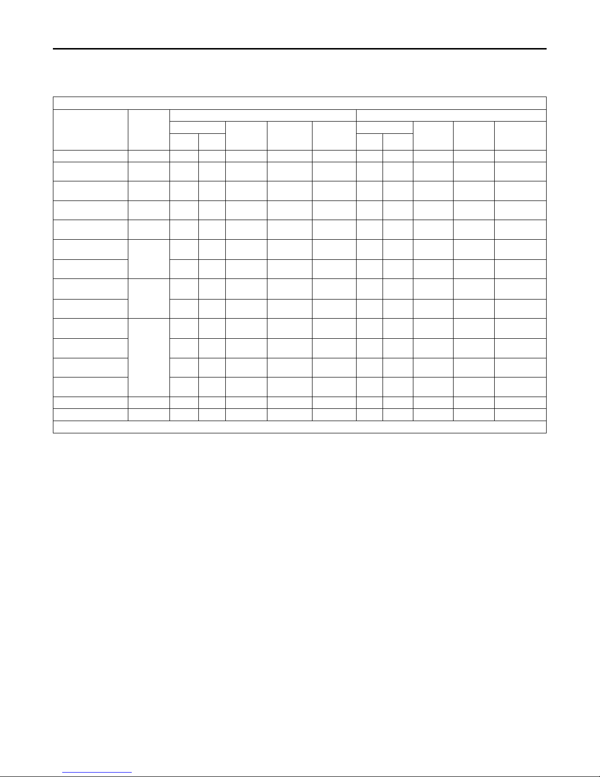
PPeerrffoorrmmaannccee aanndd EElleeccttrriiccaall DDaattaa
Table 15. Electrical Data
TEM6A0D48, TEM6A0D60 HEATER DATA
240 Volt 208 Volt
Heater
Amps per
Circuit
Minimum
Circuit
Ampacity
Maximum
Overload
Protection
Capacity
Amps per
Heater
Circuit
Minimum
Circuit
Ampacity
Heater Model No.
No. of
Circuits/
Phases
Capacity
kW BTUH kW BTUH
No Heater 6.8 * 9 15 6.8 * 9 15
BAYHTR1504BRKC
BAYHTR1504LUGB
BAYHTR1505BRKC
BAYHTR1505LUGB
BAYHTR1508BRKC
BAYHTR1508LUGB
BAYHTR1510BRKC
BAYHTR1510LUGB
BAYHTR1516BRKA
Circuit 1
(a)
BAYHTR1516BRKA
Circuit 2
BAYHTR1522BRKA
Circuit 1
(a)
BAYHTR1522BRKA
Circuit 2
BAYHTR1525BRKA
Circuit 1
(a)
BAYHTR1525BRKA
Circuit 2
BAYHTR1525BRKA
Circuit 3
BAYHTR1525BRKA
Circuit 4
BAYHTR3510LUG
BAYHTR3515LUG
1/1
1/1
1/1
1/1
2/1
2/1
4/1
1/3
1/3
3.84 13100 16.0 29 30 2.88 9800 13.8 26 30
4.80 16400 20.0 34 35 3.60 12300 17.3 30 30
7.68 26200 32.0 49 50 5.76 19700 27.7 43 45
9.60 32800 40.0 59 60 7.20 24600 34.6 52 60
9.60 32800 40.0 59 60 7.20 24600 34.6 52 60
4.80 16400 20.0 25 25 3.60 12300 17.3 22 25
9.60 32800 40.0 59 60 7.20 24600 34.6 52 60
9.60 32800 40.0 50 50 7.20 24600 34.6 43 45
6.00 20500 25.0 40 40 4.50 15400 21.6 36 40
6.00 20500 25.0 31 35 4.50 15400 21.6 27 30
6.00 20500 25.0 31 35 4.50 15400 21.6 27 30
6.00 20500 25.0 31 35 4.50 15400 21.6 27 30
9.60 32800 23.1 36 40 7.20 24600 20.0 33 35
14.40 49100 34.6 51 60 10.80 36900 30.0 45 45
* = Motor Amps
(a)
MCA and MOP for circuit 1 contains the motor amps
Maximum
Overload
Protection
18
18-GF74D1-1F-EN
Page 19
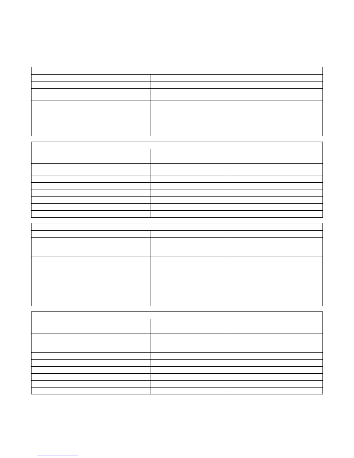
Minimum Airflow CFM
TEM6A0B24H21S, TEM6A0B30H21S
Heater Minimum Heater Airflow CFM
BAYHTR1504BRKC, BAYHTR1504LUGB
BAYHTR1505BRKC, BAYHTR1505LUGB
BAYHTR1508BRKC, BAYHTR1508LUGB
BAYHTR1510BRKC, BAYHTR1510LUGB
BAYHTR1516BRKA
BAYHTR3510LUGC
BAYHTR3515LUGC
TEM6A0C36H31S, TEM6A0C42H41S
Heater Minimum Heater Airflow CFM
BAYHTR1504BRKC, BAYHTR1504LUGB
BAYHTR1505BRKC, BAYHTR1505LUGB
BAYHTR1508BRKC, BAYHTR1508LUGB
BAYHTR1510BRKC, BAYHTR1510LUGB
BAYHTR1516BRKA
BAYHTR3510LUGC
BAYHTR3515LUGC
BAYHTR1522BRKA
With Heat Pump Without Heat Pump
550 600
800 600
825 700
1050 850
800 600
900 850
With Heat Pump Without Heat Pump
875 675
875 675
1225 825
1325 1150
875 675
1250 1150
1325 1150
Heater Minimum Heater Airflow CFM
BAYHTR1504BRKC, BAYHTR1504LUGB
BAYHTR1505BRKC, BAYHTR1505LUGB
BAYHTR1508BRKC, BAYHTR1508LUGB
BAYHTR1510BRKC, BAYHTR1510LUGB
BAYHTR1516BRKA
BAYHTR3510LUGC
BAYHTR3515LUGC
BAYHTR1522BRKA
BAYHTR1525BRKA
Heater Minimum Heater Airflow CFM
BAYHTR1504BRKC, BAYHTR1504LUGB
BAYHTR1505BRKC, BAYHTR1505LUGB
BAYHTR1508BRKC, BAYHTR1508LUGB
BAYHTR1510BRKC, BAYHTR1510LUGB
BAYHTR1516BRKA
BAYHTR3510LUGC
BAYHTR3515LUGC
BAYHTR1522BRKA
BAYHTR1525BRKA
TEM6A0C48H41S, TEM6A0C60H51S
With Heat Pump Without Heat Pump
1200 975
1200 975
1200 975
1200 975
1200 975
1200 975
1350 1125
1500 1350
TEM6A0D48H41S, TEM6A0D60H51S
With Heat Pump Without Heat Pump
1150 975
1150 975
1150 975
1325 1125
1150 975
1375 1125
1375 1125
1375 1125
18-GF74D1-1F-EN
19
Page 20
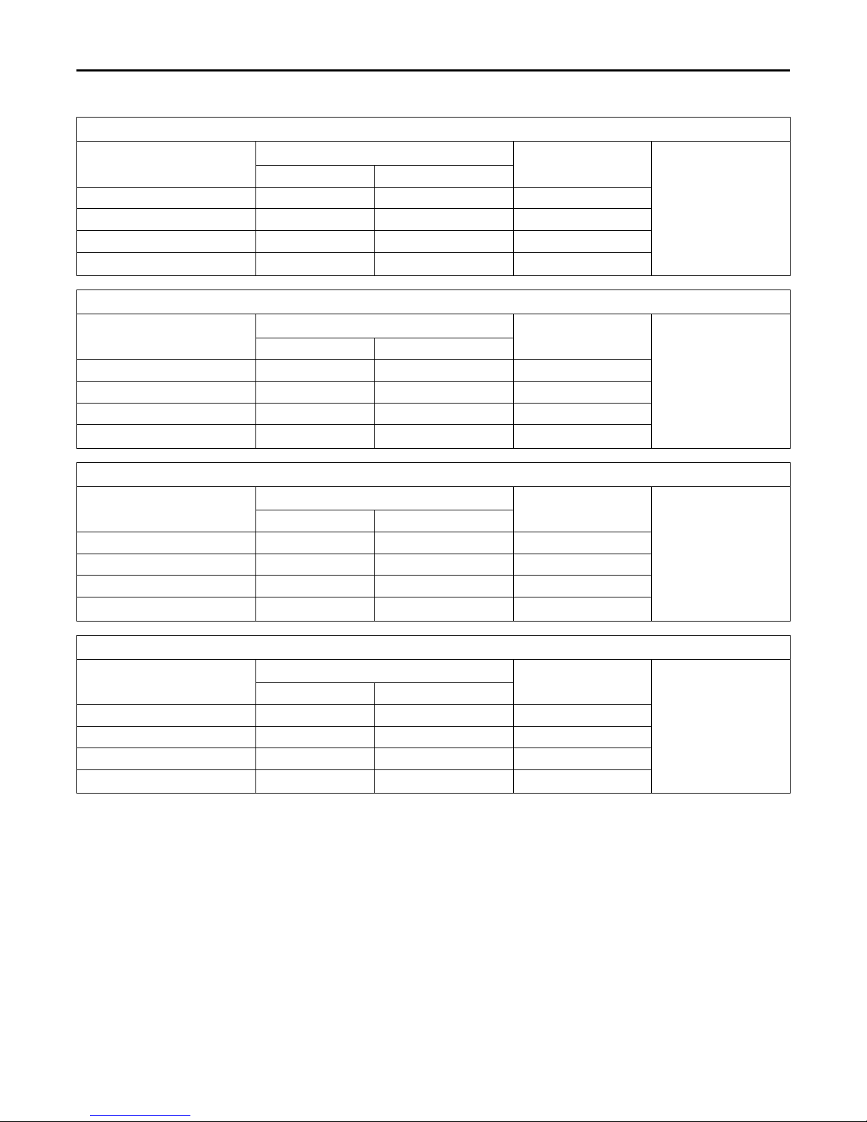
MMiinniimmuumm AAiirrffllooww CCFFMM
TEM6A0B24H21, TEM6A0B30H21 Airflow Performance with Auxiliary Heat
Airflow Settings
Low ON ON 601
Med-Lo OFF ON 723
Med-Hi ON OFF 851
High
TEM6A0C36H31, TEM6A0C42H41 Airflow Performance with Auxiliary Heat
Airflow Settings
Low ON ON 696
Med-Lo OFF ON 825
Med-Hi ON OFF 1150
High
Dip Switch Settings
Nominal Airflow
Switch 7 Switch 8
OFF OFF 973
Dip Switch Settings
Nominal Airflow
Switch 7 Switch 8
OFF OFF 1298
See following tables for
heater application:
- Pressure Drop for
Electrical Heters
- Minimum Heating
Airflow Matrix (on unit
nameplates)
See following tables for
heater application:
- Pressure Drop for
Electrical Heters
- Minimum Heating
Airflow Matrix (on unit
nameplates)
TEM6A0C48H41, TEM6A0C60H51 Airflow Performance with Auxiliary Heat
Airflow Settings
Switch 7 Switch 8
Low ON ON 1000
Med-Lo OFF ON 1130
Med-Hi ON OFF 1354
High
Dip Switch Settings
OFF OFF 1596
TEM6A0D48H41, TEM6A0D60H51 Airflow Performance with Auxiliary Heat
Airflow Settings
Switch 7 Switch 8
Low ON ON 997
Med-Lo OFF ON 1129
Med-Hi ON OFF 1350
High
Dip Switch Settings
OFF OFF 1597
Nominal Airflow
Nominal Airflow
See following tables for
heater application:
- Pressure Drop for
Electrical Heters
- Minimum Heating
Airflow Matrix (on unit
nameplates)
See following tables for
heater application:
- Pressure Drop for
Electrical Heters
- Minimum Heating
Airflow Matrix (on unit
nameplates)
20
18-GF74D1-1F-EN
Page 21
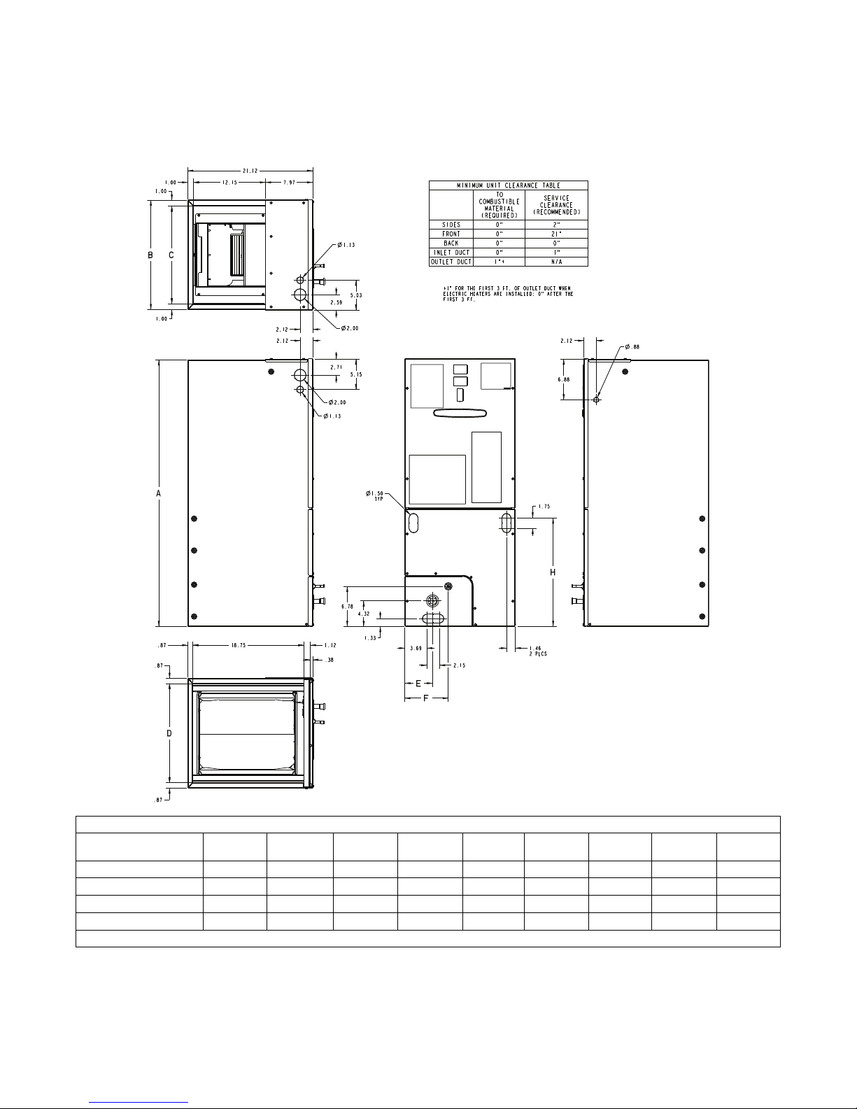
Outline Drawing
Air Handler Model A B C D E F H
TEM6A0B24, 30
TEM6A0C36, 42
TEM6A0C48, 60
TEM6A0D48, 60
All dimensions are in inches
46.77 18.50 16.50 16.75 4.68 7.33 20.09 TXV
51.27 23.50 21.50 21.75 7.01 9.66 24.59 TXV
55.87 23.50 21.50 21.75 4.68 9.66 27.19 TXV
53.87 26.50 24.50 24.75 7.01 9.66 27.19 TXV
18-GF74D1-1F-EN
PRODUCT DIMENSIONS
Flow
Control
Gas Line
Braze
3/4
7/8
7/8
7/8
21
Page 22
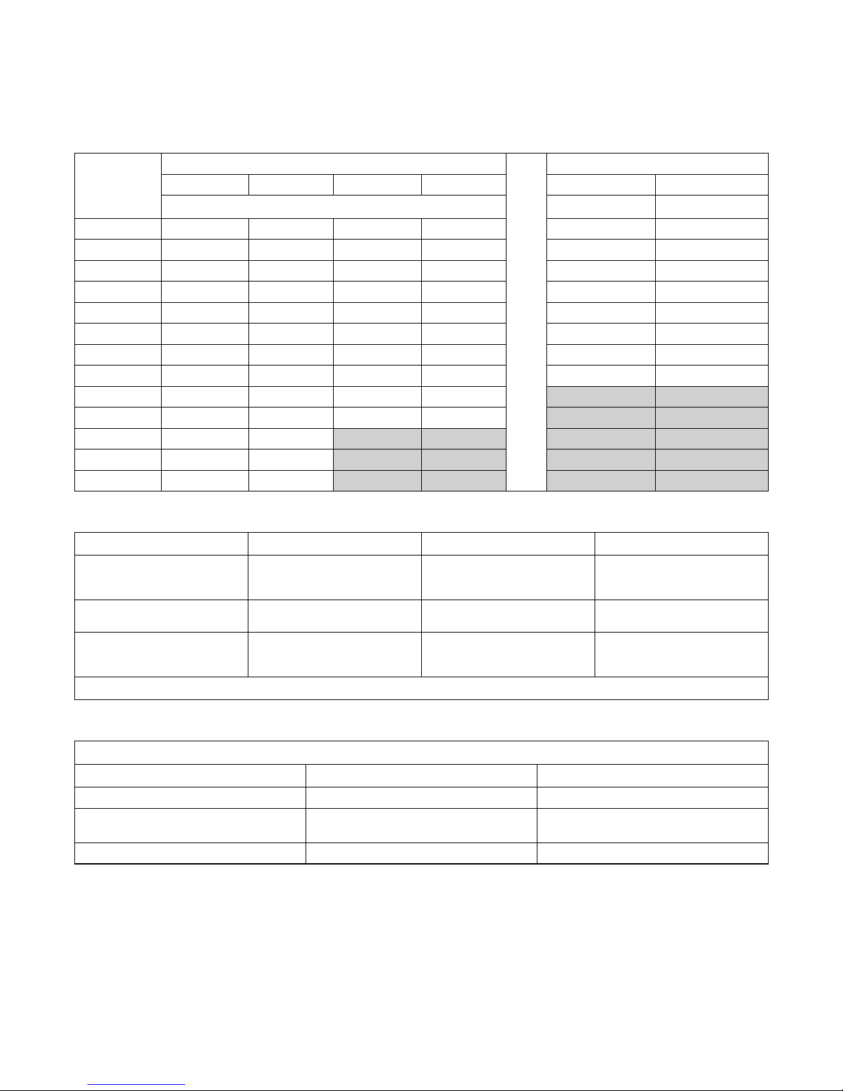
Heater Pressure Drop Table
Number of Racks Heater Racks
Airflow
CFM
1800 0.02 0.04 0.06 0.14 BAYHTR1505 1
1700 0.02 0.04 0.06 0.14 BAYHTR1508 2
1600 0.02 0.04 0.06 0.13 BAYHTR1510 2
1500 0.02 0.04 0.06 0.12 BAYHTR1516 3
1400 0.02 0.04 0.06 0.12 BAYHTR3510 3
1300 0.02 0.04 0.05 0.11 BAYHTR3515 3
1200 0.01 0.04 0.05 0.10 BAYHTR1522 4
1100 0.01 0.03 0.05 0.09 BAYHTR1525 4
1000 0.01 0.03 0.04 0.09
900 0.01 0.03 0.04 0.08
800 0.01 0.03
700 0.01 0.02
600 0.01 0.02
Subcooling Adjustment
1 2 3 4 Heater Model No. of Racks
Air Pressure Drop — Inches W.G.
BAYHTR1504 1
System Matched with: Indoor Unit Model No. Outdoor Model No. Subcooling
16 SEER HP — 2 ton TEM6A0C36H31 4TWR6024H1000A
15 SEER HP — 2 ton TEM6A0B24H21
TEM6A0B30H21
15 SEER HP — 3 ton TEM6A0B30H21
TEM6A0C36H31
TEM6A0C42H41
All other matches must be charged per the nameplate charging instructions
4TWX6024H1000A
4A6H6024H1000A
4TWR5024G1000A
4A6H5024G1000A
4TWR5036G1000A
4A6H5036G1000A
13 Degrees
14 Degrees
14 Degrees
Subcooling Adjustment for TEM6A0C48H41 & TEM6A0C60H51
Sub-Cooling Charge Specification For AHRI Rated Performance
OD Equipment Up Flow / Horizontal Down Flow
AC UNIT OD Name Plate OD Name Plate
HP UNIT ≤ 3.5 Tons OD Name Plate OD Name Plate
HP UNIT = 4 and 5 Tons OD Name Plate OD Name Plate
+ 4 Degrees
22
18-GF74D1-1F-EN
Page 23
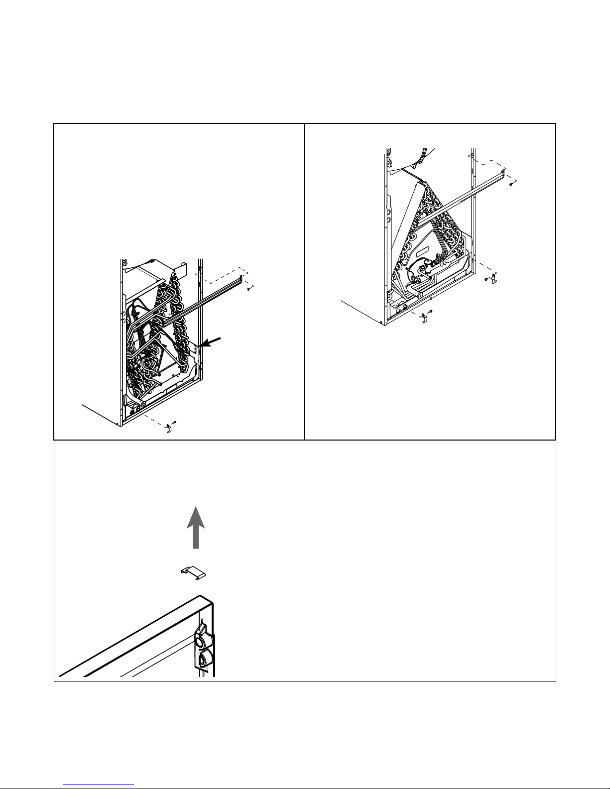
Coil Conversion Instructions
Table 16. Downflow
Follow the conversion steps when installing the air handler in
downflow configuration.
1. Remove the front panels from the air handler. The coil and line set
panel do not need to be separated.
2. Remove the fasteners on both sides of the coil.
Note: The TEM6A0C48 and TEM6A0C60 will have a coil retaining
bracket and a shipping bracket. All other coils will have
two coil retaining brackets.
3. Remove the two screws holding the center horizontal bracket and
rotate out of place. Retain parts.
Figure 4. TEM6A0C48 and TEM6A0C60 Only
Figure 5. All other models
4. For the TEM6A0C48 and TEM6A0C60, remove the drain pan
support bracket at the top of the drain pan and discard.
Note: The drain pan support bracket should be removed to avoid
tearing the cabinet insulation.
18-GF74D1-1F-EN
23
Page 24
CCooiill CCoonnvveerrssiioonn IInnssttrruuccttiioonnss
Table 16. Downflow (continued)
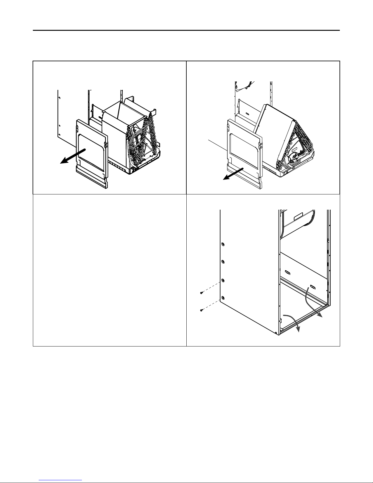
5. Slide the coil assembly out. Remove and discard the horizontal
drain pan.
Figure 6. TEM6A0C48 and TEM6A0C60 Only
Figure 7. All other models
6. On both sides of the cabinet, remove the two screws that hold the
coil support brackets and retain for later use. Seal the holes to
prevent air leakage.
7. Rotate and lift the two coil support brackets to remove from front
slots in cabinet.
Figure 8. All models
24
18-GF74D1-1F-EN
Page 25
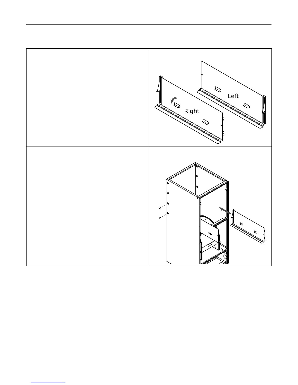
Table 16. Downflow (continued)
Left
Right
CCooiill CCoonnvveerrssiioonn IInnssttrruuccttiioonnss
8. Bend the two tabs on each of the coil support brackets. Tabs
should be bent inward so they are parallel to the bottom flange.
9. Rotate the unit into the downflow orientation.
10. Pre-drill four clearance holes in the cabinet at dimples located
below the location the screws were removed for the coil support
brackets. There are two holes per side. See location of holes
11. Replace the center horizontal bracket removed in Step 3. Use the
screws retained from Step 3 to attach.
12. Place coil support brackets into the lower set of slots and rotate
into place. Push downward to lock into place.
13. Secure each bracket with 2 screws that were previously removed.
Figure 9. All models
Figure 10. All models
18-GF74D1-1F-EN
25
Page 26
Shipping
Brackets
Rear View
of Coil
CCooiill CCoonnvveerrssiioonn IInnssttrruuccttiioonnss
Table 16. Downflow (continued)
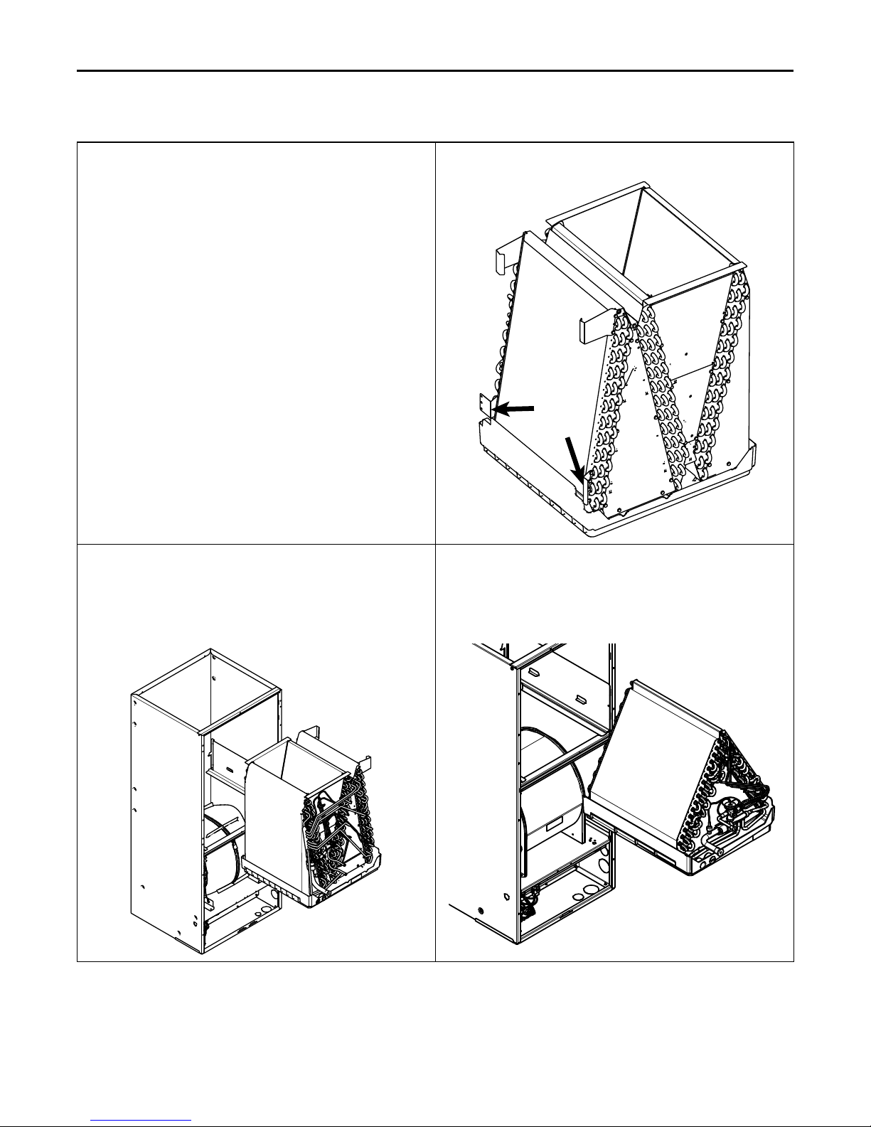
14. For the TEM6A0C48 and TEM6A0C60 models, remove the two
shipping brackets from the coil and discard.
Note: It is recommended to remove the shipping brackets from the
TEM6A0C48 and TEM6A0C60.
15. Slide the coil assembly back into the air handler cabinet as shown.
16. Remove the appropriate knock out for the condensate piping.
Figure 12. TEM6A0C48 and TEM6A0C60 Only
Figure 11. TEM6A0C48 and TEM6A0C60 Only
Figure 13. All other models
26
18-GF74D1-1F-EN
Page 27
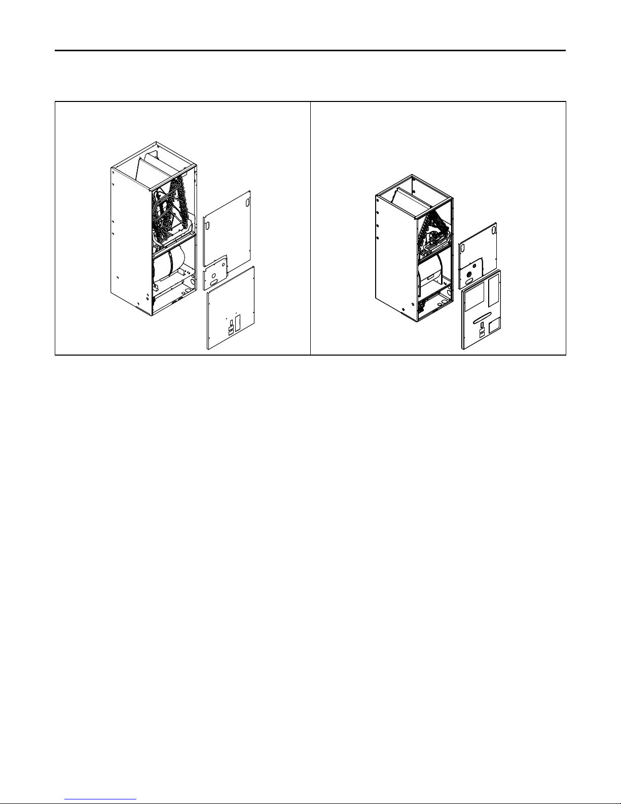
Table 16. Downflow (continued)
17. Replace all panels
Figure 14. TEM6A0C48 and TEM6A0C60 Only
CCooiill CCoonnvveerrssiioonn IInnssttrruuccttiioonnss
Figure 15. All other models
18-GF74D1-1F-EN
27
Page 28
CCooiill CCoonnvveerrssiioonn IInnssttrruuccttiioonnss
Coil Conversion
Table 17. Horizontal Right
Follow the conversion steps when installing the air handler in
horizontal right configuration.
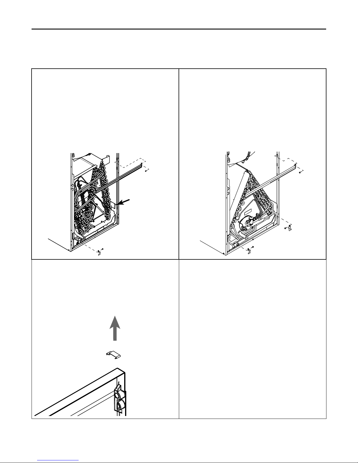
1. Remove the front panels from the air handler. The coil and line set
panel do not need to be separated.
2. Remove the fasteners on both sides of the coil. Retain the coil
retaining brackets and screws.
Note: The TEM6A0C48 and TEM6A0C60 will have a coil retaining
bracket and a shipping bracket. All other coils will have
two coil retaining brackets.
3. Remove the two screws holding the center horizontal bracket and
rotate out of place. Retain parts.
Figure 16. TEM6A0C48 and TEM6A0C60 Only
Figure 17. All other models
4. Make note of the horizontal drain pan orientation (up/down).
5. For the TEM6A0C48 and TEMA0C60, remove the drain pan
support bracket at the top of the drain pan and retain for later
use.
Note: The drain pan support bracket should be removed to avoid
tearing the cabinet insulation.
Figure 18. TEM6A0C48 and TEM6A0C60 Only
28
18-GF74D1-1F-EN
Page 29
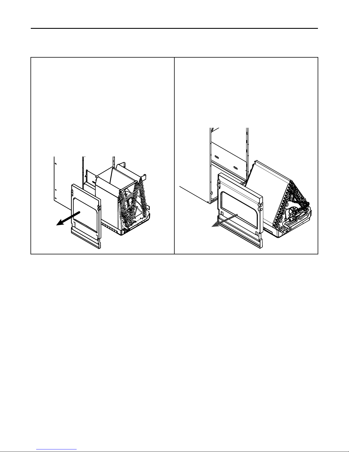
Table 17. Horizontal Right (continued)
6. Slide the coil assembly out.
7. Change location of the front and rear water diverter brackets by
removing the screws on the water diverter brackets that are
located on the left side of the coil. Attach the water diverters to
the right hand side of the coil using the same screws.
CCooiill CCoonnvveerrssiioonn IInnssttrruuccttiioonnss
Important: The coil slabs are different and the mount hole locations
will vary. See the illustrations on the following pages that
correspond to the unit tonnage to see the correct
mounting position of the water diverter bracket.
Important: The water diverter brackets are not symmetrical and will
vary by tonnage.
Important: There is no change required for the TEM6A0C48 and
TEM6A0C60 water diverters.
Figure 19. TEM6A0C48 and TEM6A0C60 Only
Figure 20. All other models
18-GF74D1-1F-EN
29
Page 30
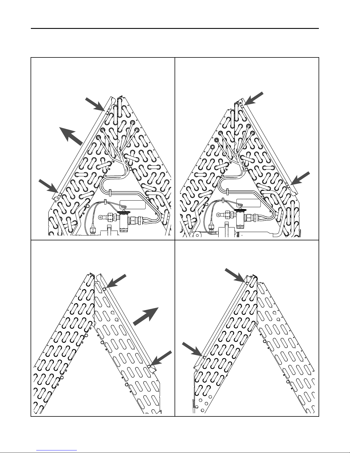
Remove 2 screws
and water diverter
bracket
TEM6A0B24 and TEM6A0B30 - Front view
Screw is located in
second hole on
tube sheet
TEM6A0B24 and TEM6A0B30 - Front view
Replace 2 screws
and water diverter
bracket
TEM6A0B24 and TEM6A0B30 - Rear view
Remove 2 screws
and water diverter
bracket
Screw is located in
second hole on
tube sheet
Replace water
diverter bracket
TEM6A0B24 and TEM6A0B30 - Rear view
CCooiill CCoonnvveerrssiioonn IInnssttrruuccttiioonnss
Table 17. Horizontal Right (continued)
Figure 21.
Figure 22.
Figure 23.
Figure 24.
30
18-GF74D1-1F-EN
Page 31
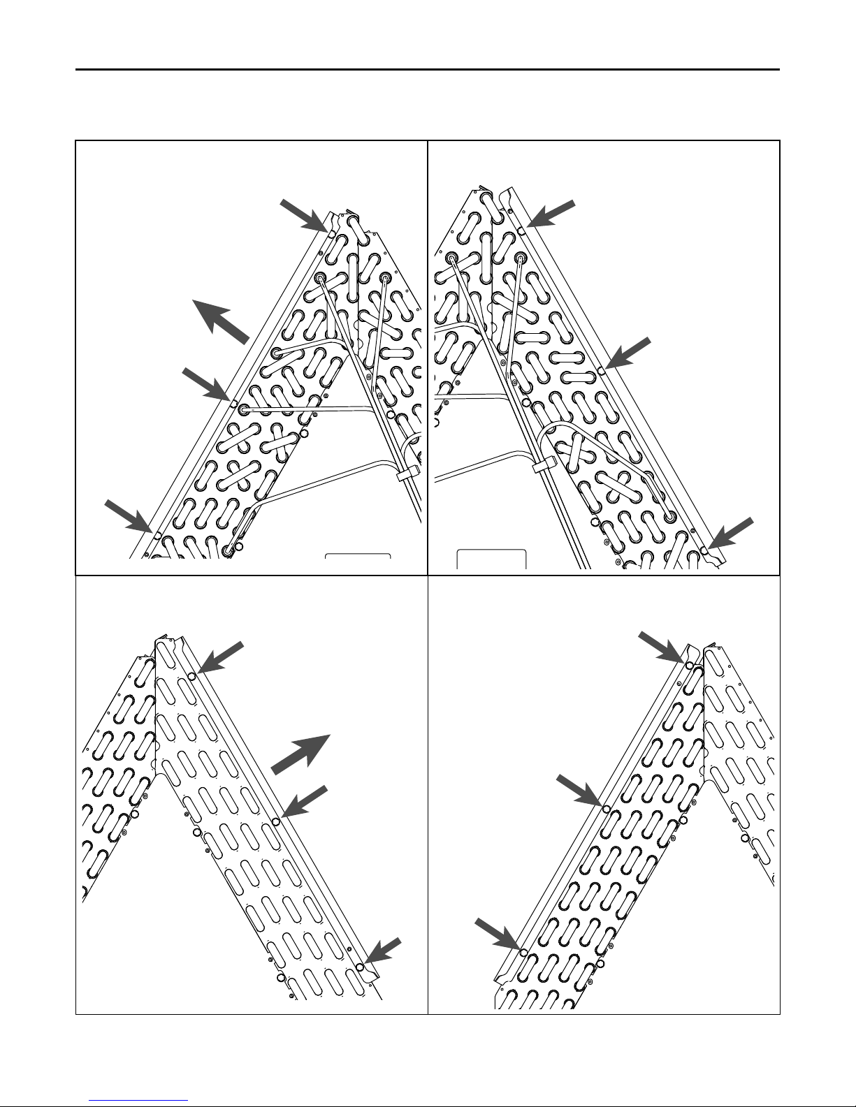
Table 17. Horizontal Right (continued)
Remove 3 screws
and water diverter
bracket
TEM6A0C36 and TEM6A0C42 models -Front view
Screw is located in
second hole on
tube sheet
Replace 3 screws
and water diverter
bracket
TEM6A0C36 and TEM6A0C42 models
-Front vi
ew
Remove 3 screws
and water diverter
bracket
TEM6A0C36 and TEM6A0C42 models -Rear view
Screw is located in
uppermost hole on
tube sheet
Replace 3 screws
and water diverter
bracket
TEM6A0C36 and TEM6A0C42 models -Rear view
CCooiill CCoonnvveerrssiioonn IInnssttrruuccttiioonnss
Figure 25.
Figure 26.
Figure 27.
Figure 28.
18-GF74D1-1F-EN
31
Page 32
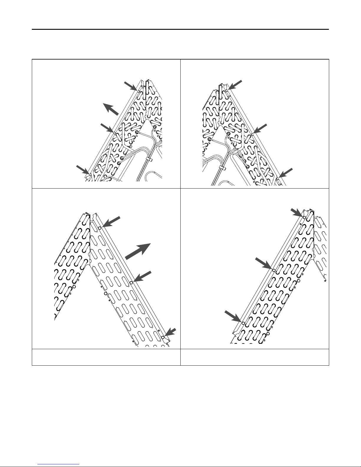
TEM6A0D48 and TEM6A0D60 models
- Front view
Remove 3 screws
and water diverter
bracket
Screw is located in
second hole on
tube sheet
TEM6A0D48 and TEM6A0D60 models - Front view
Replace 3 screws
and water diverter
bracket
TEM6A0D48 and TEM6A0D60 models - Rear view
Remove 3 screws
and water diverter
bracket
TEM6A0D48 and TEM6A0D60 models
- Rear view
Replace 3 screws
and water diverter
bracket
Screw is located in
second hole on
tube sheet
CCooiill CCoonnvveerrssiioonn IInnssttrruuccttiioonnss
Table 17. Horizontal Right (continued)
Figure 29.
Figure 31.
Figure 30.
Figure 32.
Important: There is no change required for the TEM6A0C48 and
32
TEM6A0C60 water diverters.
18-GF74D1-1F-EN
Page 33
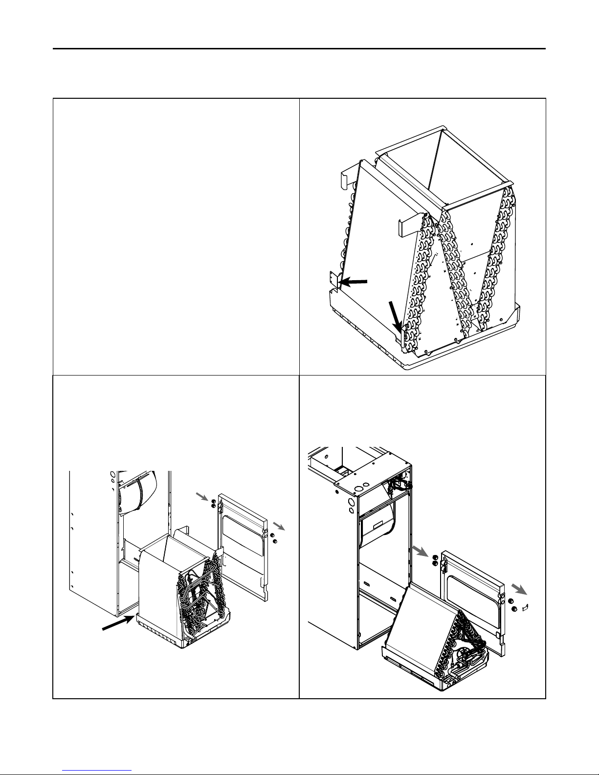
Table 17. Horizontal Right (continued)
Shipping
Brackets
Rear View
of Coil
CCooiill CCoonnvveerrssiioonn IInnssttrruuccttiioonnss
8. For the TEM6A0C48 and TEM6A0C60 models, remove the two
shipping brackets from the coil and discard.
9. Relocate the horizontal drain pan from the left side of the coil to
the right side.
10. Remove the two drain plugs and the drain pan support bracket
from the front of the drain pan and insert them in the drains at the
rear of the drain pan.
Note: For the TEM6A0C48 and TEM6A0C60, the drain pan
support bracket should have been removed earlier.
Figure 34. TEM6A0C48 and TEM6A0C60 Only
Figure 33. TEM6A0C48 and TEM6A0C60 Only
Figure 35. All other models
Important: When reinstalling coil in Step 12, it is important that the
coil corner locks in place under the tab in the side bracket
to support the coil weight horizontally.
18-GF74D1-1F-EN
33
Page 34
CCooiill CCoonnvveerrssiioonn IInnssttrruuccttiioonnss
Table 17. Horizontal Right (continued)
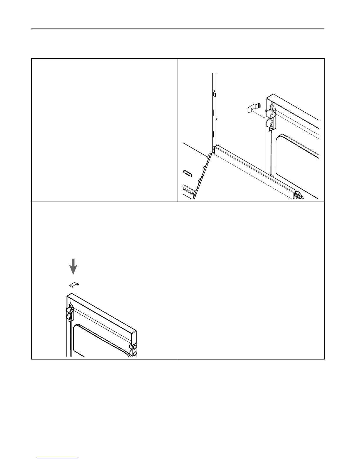
11. Reinstall the drain pan support bracket. The bracket should be
located between the two drain plugs as shown.
Note: For the TEM6A0C48 and TEM6A0C60 models only, to avoid
tearing the interior insulation, the drain pan support bracket
should be installed after the coil has been put into the unit in
Step 12.
12. Slide the coil assembly back into the air handler cabinet.
IMPORTANT: Make sure that the coil corner locks in place under
the tab in the side left bracket to support the coil
weight in the horizontal right position.
13. For the TEM6A0C48 and TEMA0C60 only, install the drain pan
support bracket on the top of the drain pan opposite the drain
ports and as close to the end as possible
Figure 37. TEM6A0C48 and TEM6A0C60 Only
Figure 36. All other models
34
18-GF74D1-1F-EN
Page 35
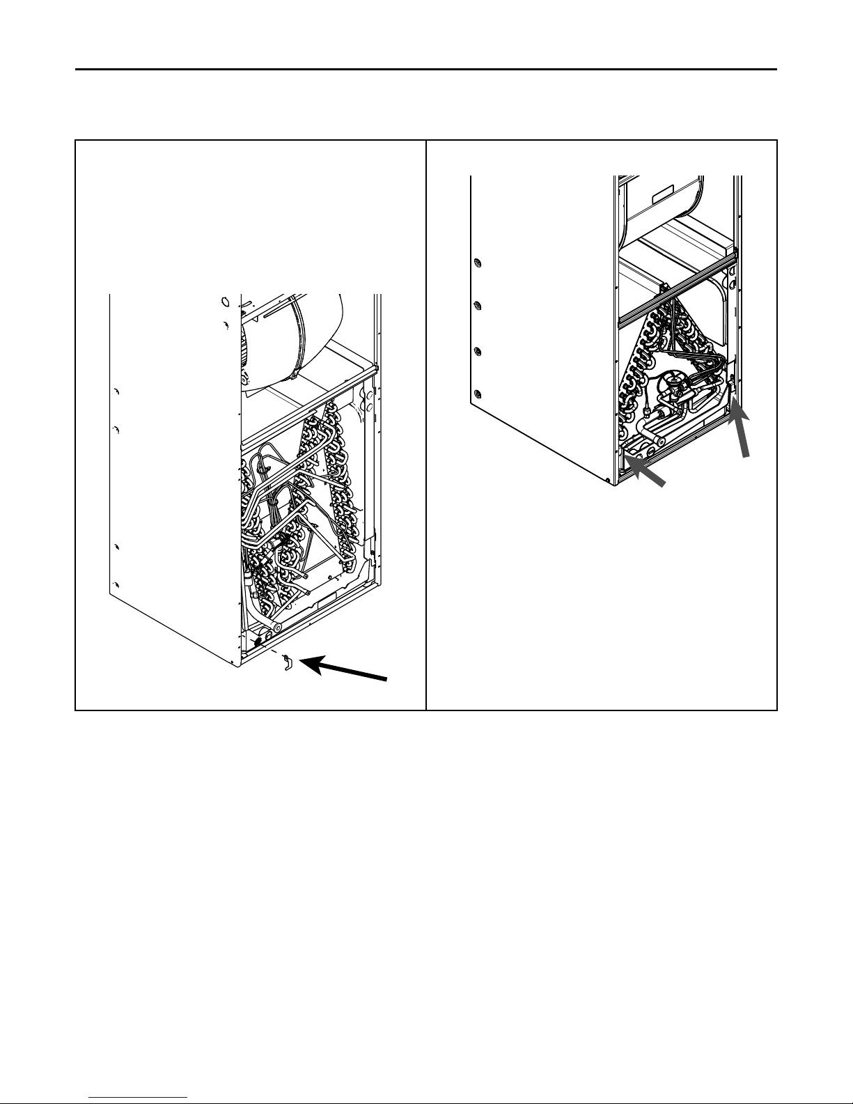
Table 17. Horizontal Right (continued)
CCooiill CCoonnvveerrssiioonn IInnssttrruuccttiioonnss
14. Replace the center horizontal bracket using screws removed
earlier in Step 3.
15. Replace the two coil retaining brackets removed in a previous
step.
Note: The TEM6A0C48 and TEM6A0C60 will have only one coil
retaining bracket.
16. Replace all panels.
Figure 38. TEM6A0C48 and TEM6A0C60 Only
Figure 39. All other models
18-GF74D1-1F-EN
35
Page 36
Checkout Procedures
The final phase of the installation is the system Checkout Procedures. The following list represents the most common items covered in a
Checkout Procedure. Confirm all requirements in this document have been met.
All wiring connections are tight and properly secured.
Voltage and running current are within limits.
All refrigerant lines (internal and external to equipment) are
isolated, secure, and not in direct contact with each other or
structure.
All braze connections have been checked for leaks. A vacuum of
350 microns provides confirmation that the refrigeration system
is leak free and dry.
Final unit inspection to confirm factory tubing has not shifted
during shipment. Adjust tubing if necessary so tubes do not rub
against each other or any component when unit runs.
Ductwork is sealed and insulated.
All drain lines are clear with joints properly sealed. Pour water
into drain pan to confirm proper drainage.
Supply registers and return grilles are open, unobstructed, and
air filter is installed.
Indoor blower and outdoor fan are operating smoothly and
without obstruction.
Indoor blower motor set on correct speed setting to deliver
required CFM.
Cover panels are in place and properly tightened.
For gas heating systems, manifold pressure has been checked
and all gas line connections are tight and leak free.
For gas heating systems, flue gas is properly vented.
System functions safely and properly in all modes.
Owner has been instructed on use of system and given manual.
The manufacturer optimizes the performance of homes and buildings around the world. A business of Ingersoll Rand,
the leader in creating and sustaining safe, comfortable and energy efficient environments, the manufacturer offers a
broad portfolio of advanced controls and HVAC systems, comprehensive building services, and parts. For more
information, visit www.IRCO.com.
The manufacturer has a policy of continuous product and product data improvements and reserves the right to change design and specifications without notice.
©2016 Trane
18-GF74D1-1F-EN
Supersedes 18-GF74D1-1E-EN (December 2015)
15 Jan 2016
 Loading...