

Page 1

03537818
REV.000
Form P6934
Edition 7
September, 1999
OPERATION AND MAINTENANCE
TPD1430
MANUAL FOR SERIES
TD, TX AND TXD GRINDERS
Series TD, TX and TXD Grinders are designed for close–quarter work in the metal fabricating
industry, shipyards, pipe fabrication, die manufacturing and limited space applications. They
are particularly good where conduits, pipes, ducts, etc. pass through bulkheads or frames.
These small Grinders are very efficient for grinding weld bead and leaving a fine finish.
Ingersoll–Rand is not responsible for customer modification of tools for applications on which
Ingersoll–Rand was not consulted.
IMPORTANT SAFETY INFORMATION ENCLOSED.
READ THIS MANUAL BEFORE OPERATING TOOL.
IT IS THE RESPONSIBILITY OF THE EMPLOYER TO PLACE THE INFORMATION
IN THIS MANUAL INTO THE HANDS OF THE OPERATOR.
FAILURE TO OBSERVE THE FOLLOWING WARNINGS COULD RESULT IN INJURY.
PLACING TOOL IN SERVICE
• Always operate, inspect and maintain this tool in
accordance with American National Standards
Institute Safety Code for Portable Air Tools
(ANSI B186.1).
• For safety, top performance, and maximum durability
of parts, operate this tool at 90 psig (6.2 bar/620 kPa)
maximum air pressure at the inlet with 3/8” (10 mm)
inside diameter air supply hose.
• Always turn off the air supply and disconnect the air
supply hose before installing, removing or adjusting
any accessory on this tool, or before performing any
maintenance on this tool.
• Do not use damaged, frayed or deteriorated air hoses
and fittings.
• Be sure all hoses and fittings are the correct size and
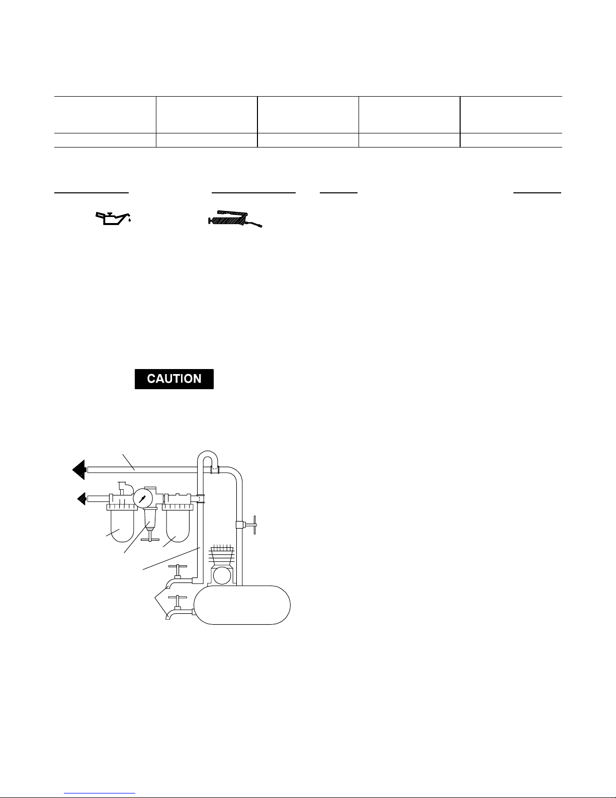
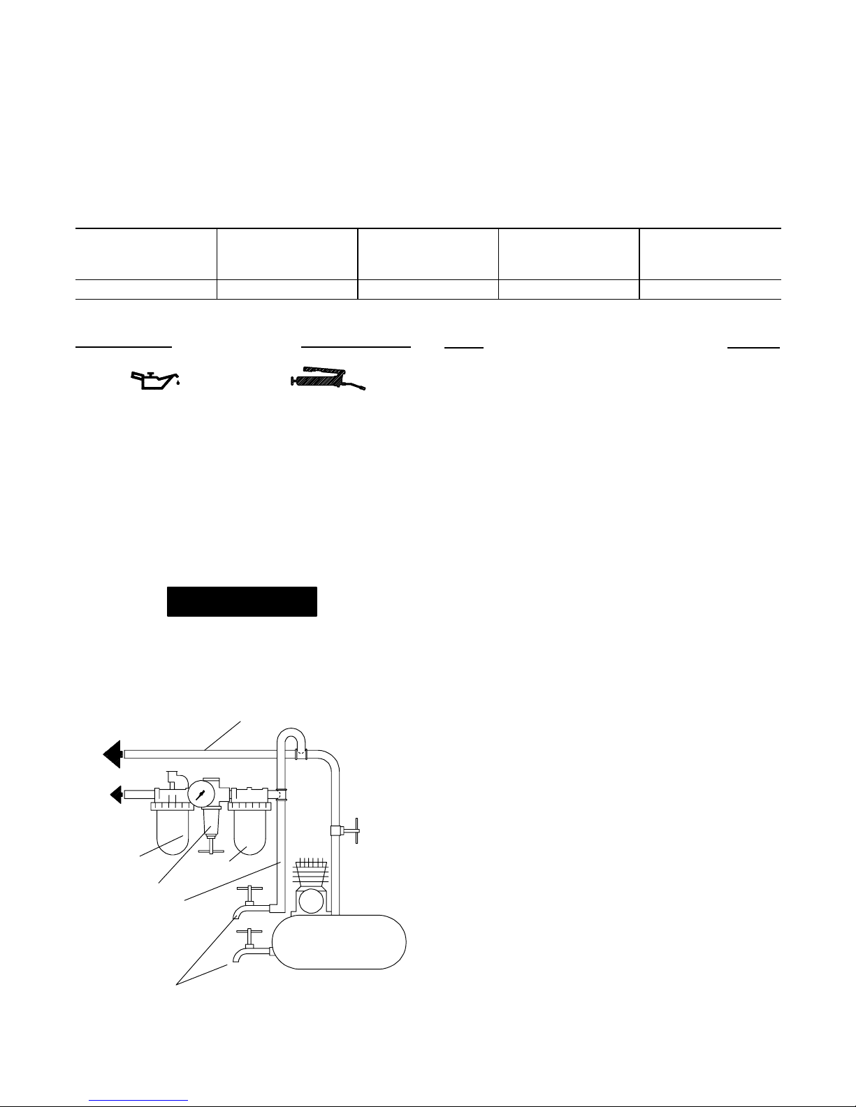
are tightly secured. See Dwg. TPD905–1 for a typical
piping arrangement.
• Always use clean, dry air at 90 psig maximum air
pressure. Dust, corrosive fumes and/or excessive
moisture can ruin the motor of an air tool.
• Do not lubricate tools with flammable or volatile
liquids such as kerosene, diesel or jet fuel.
• Do not remove any labels. Replace any damaged label.
USING THE TOOL
• Always wear eye protection when operating or
performing maintenance on this tool.
• Always wear hearing protection when operating this
tool.
• Keep hands, loose clothing and long hair away from
rotating end of tool.
• Anticipate and be alert for sudden changes in motion
during start up and operation of any power tool.
• Keep body stance balanced and firm. Do not
overreach when operating this tool. High reaction
torques can occur at or below the recommended air
pressure.
• Tool accessories may continue to rotate briefly after
throttle is released.
• Air powered tools can vibrate in use. Vibration,
repetitive motions or uncomfortable positions may be
harmful to your hands and arms. Stop using any tool
if discomfort, tingling feeling or pain occurs. Seek
medical advice before resuming use.
• Use accessories recommended by Ingersoll–Rand.
• This tool is not designed for working in explosive
atmospheres.
• This tool is not insulated against electric shock.
F
E
P
The use of other than genuine Ingersoll–Rand replacement parts may result in safety hazards, decreased tool performance, and
increased maintenance, and may invalidate all warranties.
Repairs should be made only by authorized trained personnel. Consult your nearest Ingersoll–Rand Authorized Servicenter.
Refer All Communications to the Nearest
Ingersoll–Rand Office or Distributor.
Ingersoll–Rand Company 1999
Printed in U.S.A.
Page 2
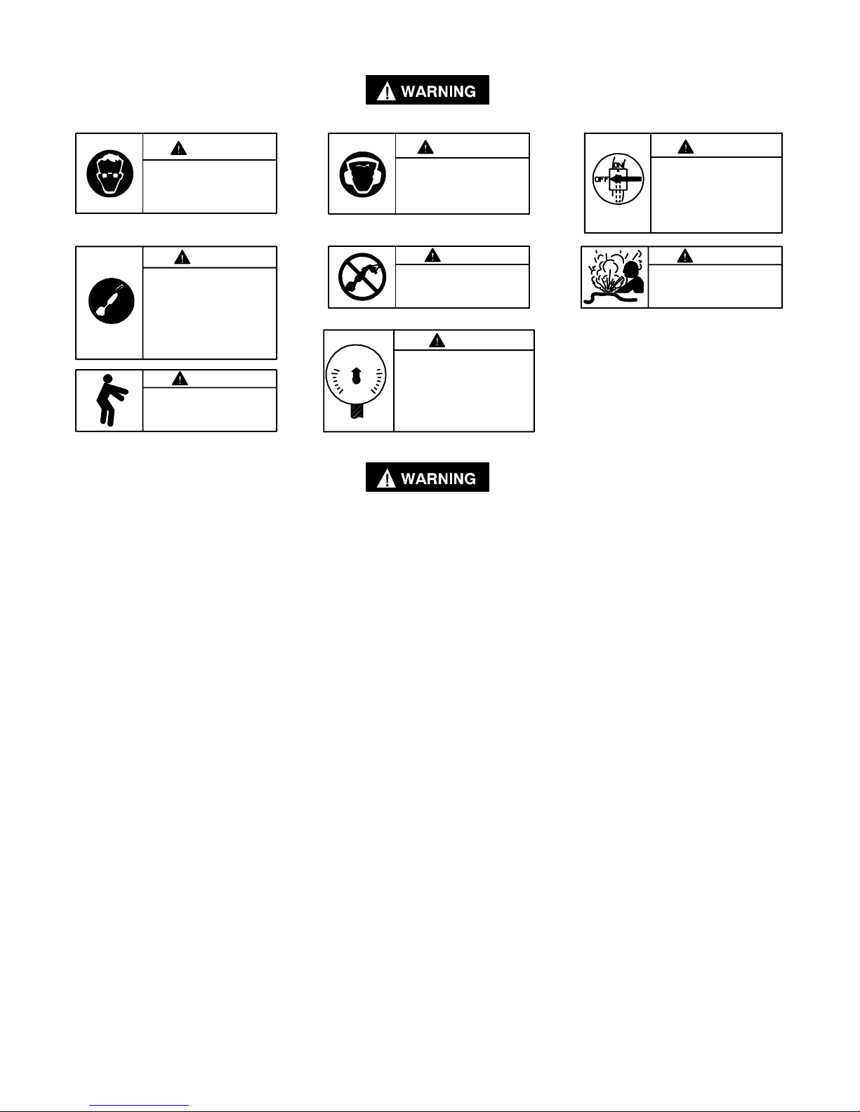
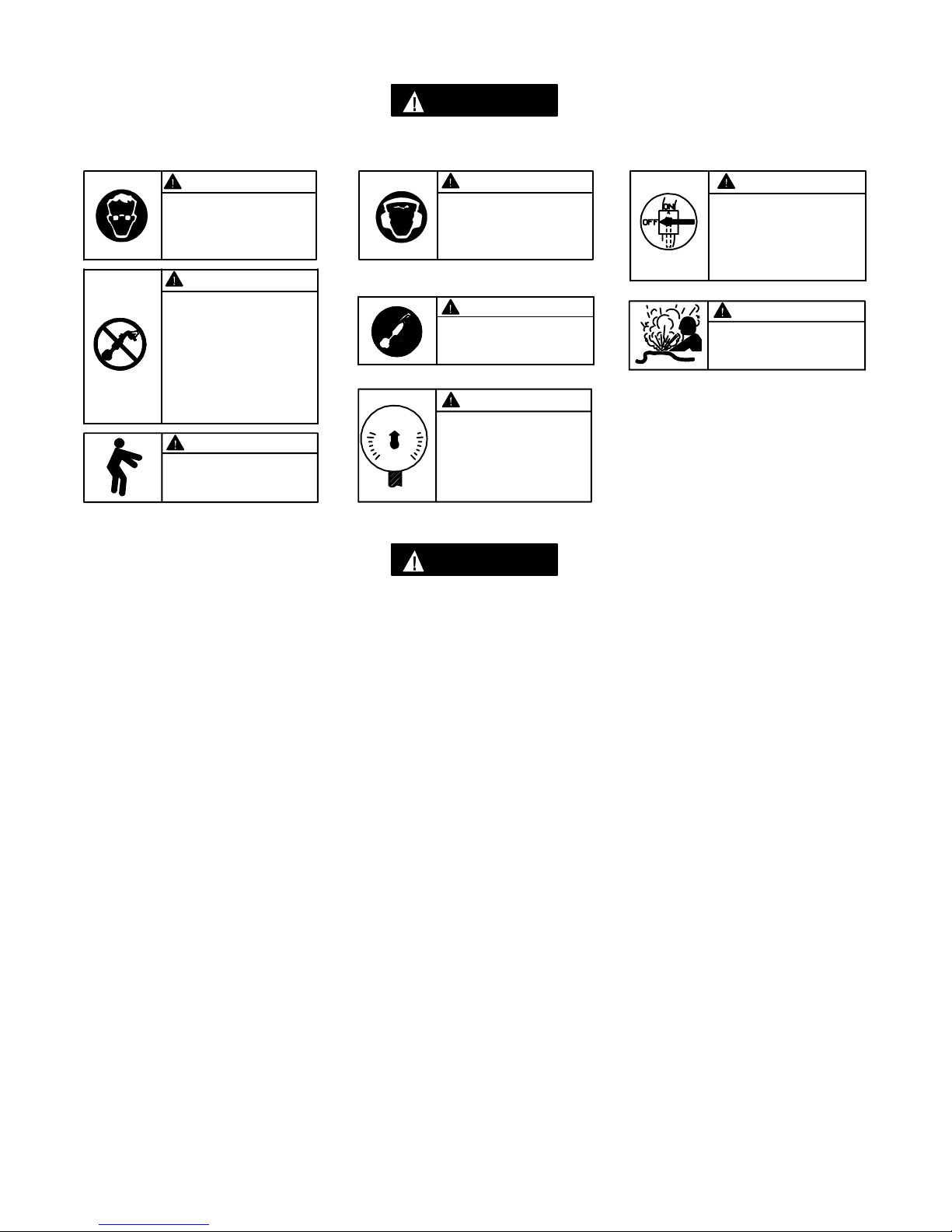
W ARNING LABEL IDENTIFICATION
REV.000
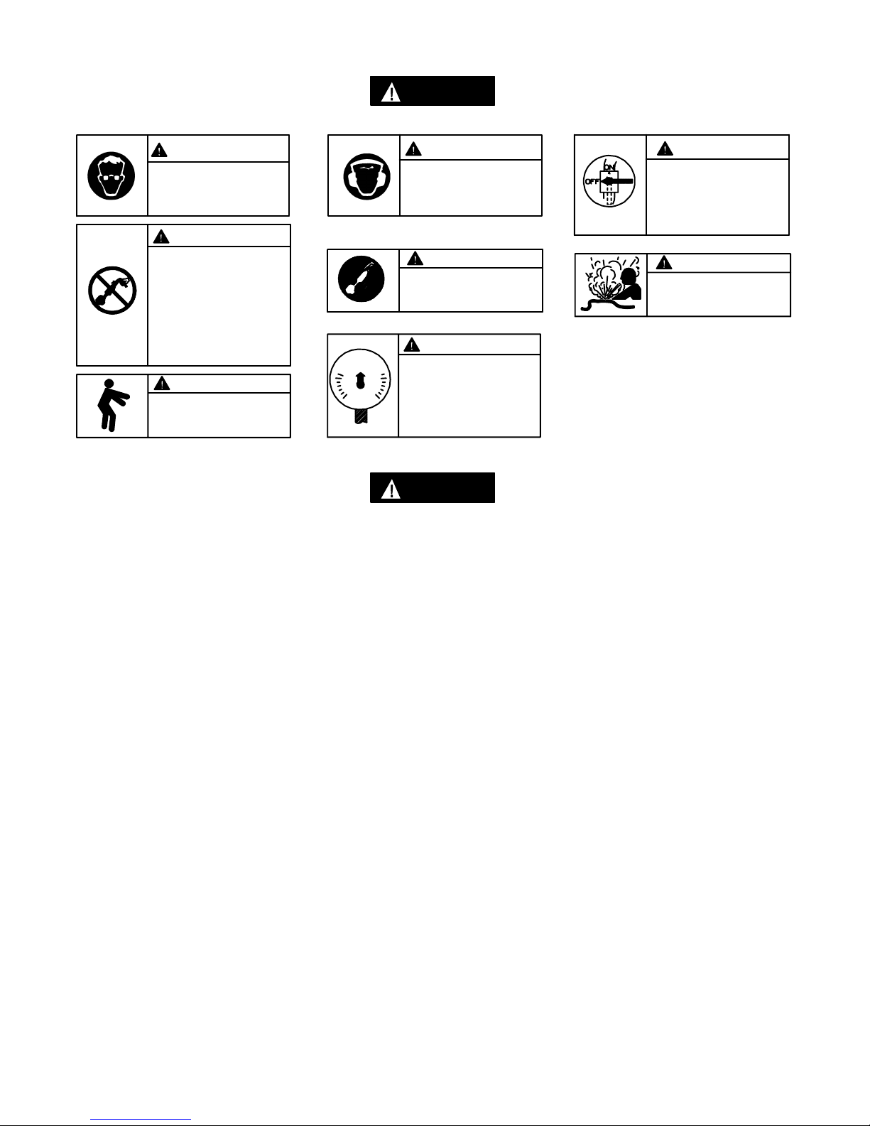
FAILURE TO OBSERVE THE FOLLOWING WARNINGS COULD RESULT IN INJURY.
WARNING
Always wear eye protection
when operating or performing maintenance on this
tool.
WARNING
Air powered tools can vibrate
in use. Vibration, repetitive
motions or uncomfortable positions may be harmful to your
hands and arms. Stop using
any tool if discomfort, tingling
feeling or pain occurs. Seek
medical advice before resuming use.
90 psig
(6.2bar/620kPa)
WARNING
Keep body stance balanced
and firm. Do not overreach
when operating this tool.
GRINDER SPECIFIC WARNINGS
FAILURE TO OBSERVE THE FOLLOWING WARNINGS COULD RESULT IN INJURY.
• Do not use this tool if actual free speed exceeds the
nameplate rpm.
• Before mounting a wheel, after any tool repair or
whenever a Grinder is issued for use, check free
speed of Grinder with a tachometer to make certain
its actual speed at 90 psig (6.2 bar/620 kPa) does not
exceed rpm stamped or printed on the nameplate.
Grinders in use on the job must be similarly
checked at least once each shift.
• Always use the recommended Ingersoll–Rand
Wheel Guard furnished with the Grinder.
• Do not use any grinding wheel, bur or other
accessory having a maximum operating speed less
than the free speed of the Grinder in which it is
being used. Always conform to maximum rpm on
grinding wheel blotters.
• Inspect all grinding wheels for chips or cracks prior to
mounting. Do not use a wheel that is chipped or
cracked or otherwise damaged. Do not use a wheel
that has been soaked in water or any other liquid.
• Make certain grinding wheel properly fits the
arbor. Do not use reducing bushings to adapt a
wheel to any arbor unless such bushings are
supplied by and recommended by the wheel
manufacturer.
• After mounting a new wheel, hold the Grinder
under a steel workbench or inside a casting and run it
for at least 60 seconds. Make certain no one is
within the operating plane of the grinding wheel. If
a wheel is defective, improperly mounted or the
wrong size and speed, this is the time it will usually
fail.
WARNING
Always wear hearing
protection when operating
this tool.
WARNING
Do not carry the tool by
the hose.
WARNING
Operate at 90 psig (6.2 bar/
620 kPa) Maximum air pressure.
• When starting with a cold wheel, apply it to the
work slowly until the wheel gradually warms up.
Make smooth contact with the work and avoid
any bumping action or excessive pressure.
• Always replace a damaged, bent or severely worn
wheel guard. Do not use a wheel guard that has
been subjected to a wheel failure.
• Make certain wheel flanges are at least 1/3 the
diameter of grinding wheel, free of nicks, burrs and
sharp edges. Always use wheel flanges furnished by
the manufacturer; never use a makeshift flange or a
plain washer. Tighten Flange Nut securely.
• Guard opening must face away from operator.
Bottom of wheel must not project beyond guard.
• Series TD120 Grinders have a free speed of 12,000
rpm; Series TD180, TX180 and TXD180 Grinders
have a free speed of 18,000 rpm; Series TD200 and
TX200 Grinders have a free speed of 25,000 rpm,
when operated at 90 psig (6.2 bar/620 kPa) air
pressure. Operation at higher air pressure will result
in excessive speed.
• Always match collet size with accessory shank size.
• Always insert tool shank no less than 10 mm in the
collet. Tighten Collet Nut securely to prevent
accessory from working out during operation of the
Grinder. Check tightness of Collet Nut before
operating the Grinder. Pay particular attention to
the fact that allowed speed of a mounted point is
lowered when the length of the shaft is increased
between end of collet and mounted point (overhang).
WARNING
Always turn off the air supply and disconnect the air
supply hose before installing, removing or adjusting
any accessory on this tool,
or before performing any
maintenance on this tool.
WARNING
Do not use damaged, frayed
or deteriorated air hoses
and fittings.
2
Page 3
GRINDER SPECIFIC WARNINGS
REV.000
WARNING: Incorrect combinations of grinding wheel, wheel guard and tool speed could result in injury.
Correct combinations are specified below:
Guard Part Number Wheel Type Wheel Diameter
in. (mm)
Maximum Wheel
Thickness
Maximum Speed
rpm
in. (mm)
LE2–931 1 3 (76) 1/2 (12.7) 20 500
PLACING TOOL IN SERVICE
LUBRICATION
Ingersoll–Rand No. 10 Ingersoll–Rand No. 68
Ingersoll–Rand No. 50
Always use an air line lubricator with these tools.
We recommend the following Filter–Lubricator–Regulator
Unit:
For USA – No. C28–04–FKG0–28
After each two hours of operation, if an air line lubricator is
not used, inject 1/2 to 1 cc of Ingersoll–Rand No. 10 Oil into
the Air Inlet.
Do not mark any nonmetallic surface of this tool with
customer identification codes. Such action could affect tool
performance.
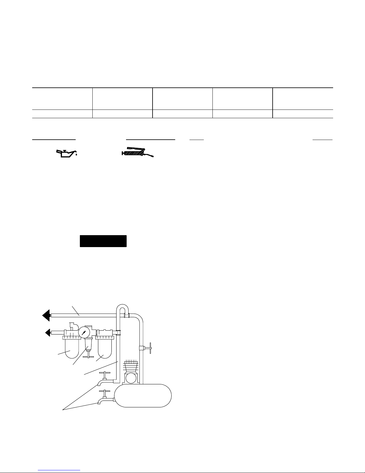
MAIN LINES 3 TIMES
AIR TOOL INLET SIZE
TO
AIR
SYSTEM
TO
AIR
TOOL
LUBRICATOR
REGULATOR
BRANCH LINE 2 TIMES
AIR TOOL INLET SIZE
DRAIN REGULARLY
FILTER
COMPRESSOR
(Dwg. TPD905–1)
To mount a TD–RK4 or TD–RK6 Router Attachment to a
TD200 or TD250 Grinder having a collet, proceed as follows:
1. Use the Collet Body Wrench to hold the Collet Body
2. Grasp the tool in copper–covered or leather–covered vise
3. Remove the Clamp Spacer and install the Router
4. Thread the Clamp Nut onto the Housing and tighten the
5. Insert the Collet into the Collet Body and loosely thread
6. Install the Nosepiece Adapter over the bit and collet
7. Install the Adapter Lock Screw in the Adapter and
8. Thread the Lock Nut onto the Nosepiece Adapter.
9. Thread the Nosepiece Assembly onto the Adapter and
10. If a Trimmer Guide is used, thread the Guide into the
MOUNTING THE ROUTER
ATTACHMENT
from turning and using the Collet Nut Wrench , unscrew
and remove the Collet Nut Assembly from the Grinder.
Remove the Collet .
jaws with the spindle upward and using a 1–1/2” wrench,
unscrew and remove the Clamp Nut . This is a left–hand
thread, rotate the Nut clockwise to remove it.
Attachment Clamp Spacer .
Nut between 20 and 25 ft–lb (27 and 34 Nm) torque. This
is a left–hand thread, rotate the Nut counterclockwise
to tighten it.
the Collet Nut onto the Collet Body. Insert a router bit
into the Collet and tighten the Collet Nut.
assembly and thread it onto the Clamp Spacer. Tighten
the Adapter between 2 and 3 ft–lb (2.7 and 4.0 Nm)
torque. This is a left–hand thread, rotate the Adapter
counterclockwise to tighten it.
tighten it between 12 and 18 in–lb (1.3 and 2.0 Nm)
torque.
then back the Lock Nut against the Assembly. Tighten the
Lock Nut between 14 and 19 ft–lb (19.0 and 25.8 Nm)
torque.
Nosepiece Assembly and tighten the Guide between 3
and 4 ft–lb (4.1 and 5.4 Nm) torque.
3
Page 4
PLACING TOOL IN SERVICE
REV.000
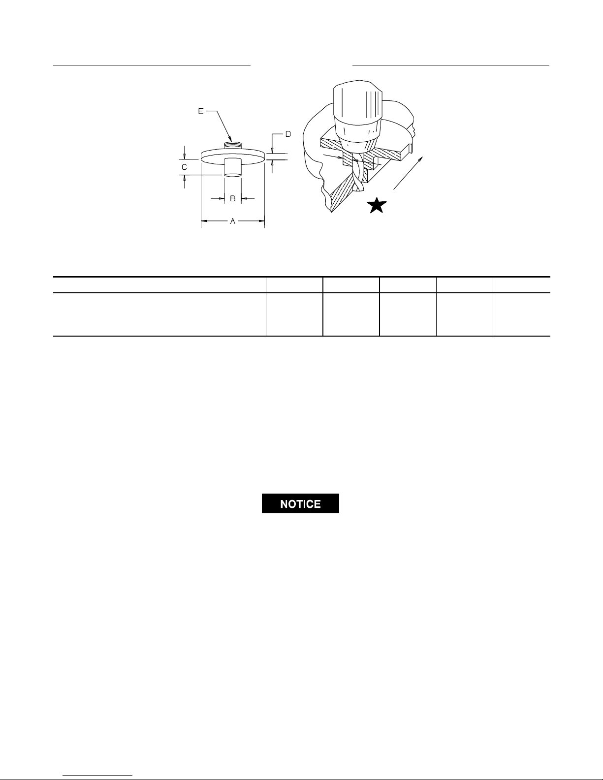
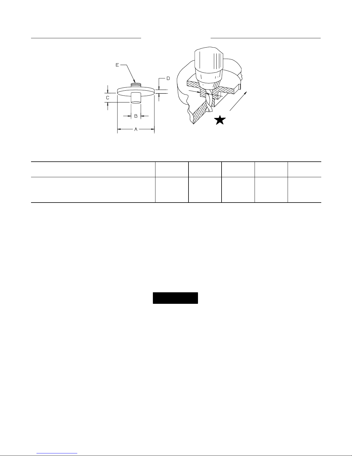
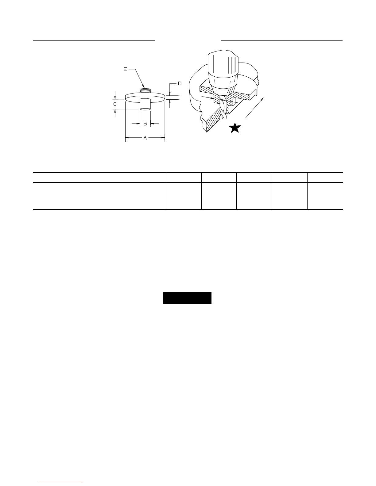
TRIMMER GUIDE
OFFSET
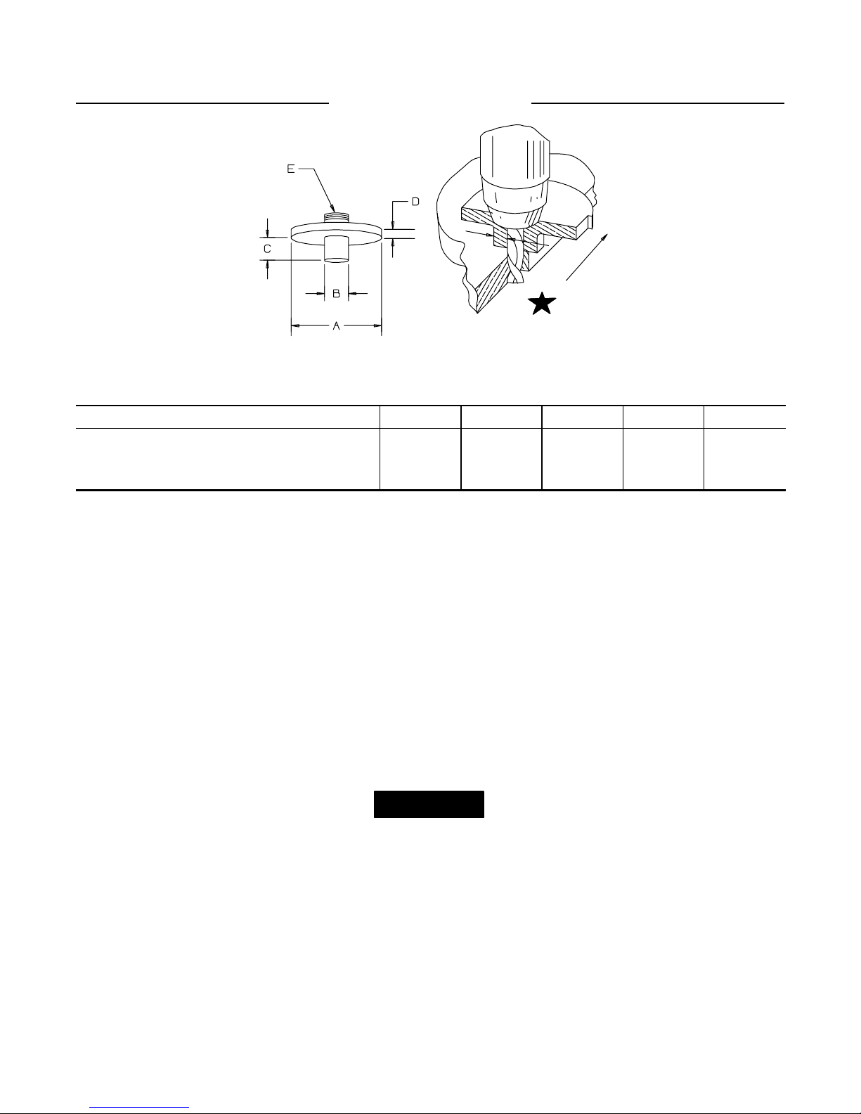
Trimmer Guide Dimensions
(Dwg. TPD1208)
PART NUMBER FOR ORDERING A B C D E
R120–128–2 (for 1/4” shank) 1–1/2 3/8 3/8 1/8 1/2–20NF
R120–128–7 (for 1/4” shank) 2–1/2 1/2 1/2 3/16 1/2–20NF
LG2–129–1 (for 3/8” shank) 2–1/2 1/2 5/8 1/8 5/8–18UNF
K Note: Offset = 1/2 (“B” dimension minus trimmer bit diameter.)
The following equipment is available at an extra price and must be ordered separately:
1. Router Attachment Assembly
for models using 1/4” diameter bits Part No. TD–RK4. . . . . . . . . . . . . . . . . . . . . . . . . . . . . . . . . . . . . . . . . . .
for models using 3/8” diameter bits Part No. TD–RK6. . . . . . . . . . . . . . . . . . . . . . . . . . . . . . . . . . . . . . . . . . .
2. Trimmer Guide (for Router Attachments)
for 1/4” shank Part No. R120–128–2. . . . . . . . . . . . . . . . . . . . . . . . . . . . . . . . . . . . . . . . . . . . . . . . . . . . . . . . . . . .
for 1/4” shank Part No. R120–128–7. . . . . . . . . . . . . . . . . . . . . . . . . . . . . . . . . . . . . . . . . . . . . . . . . . . . . . . . . . . .
for 3/8” shank Part No. LG2–129–1. . . . . . . . . . . . . . . . . . . . . . . . . . . . . . . . . . . . . . . . . . . . . . . . . . . . . . . . . . . .
All the models listed on Page 5 can be changed to front exhaust tools by reversing the Flow Ring and aligning the the indicator
marks with the letter “F” on the Housing. To order a front exhaust tool fr om the factory, substitute the letter “F” for the letter
“R” in the above models. Example: TD12RG4 Rear Exhaust Model becomes TD120FG4 Front Exhaust Model.
4
Page 5
PLACING TOOL IN SERVICE
REV.000
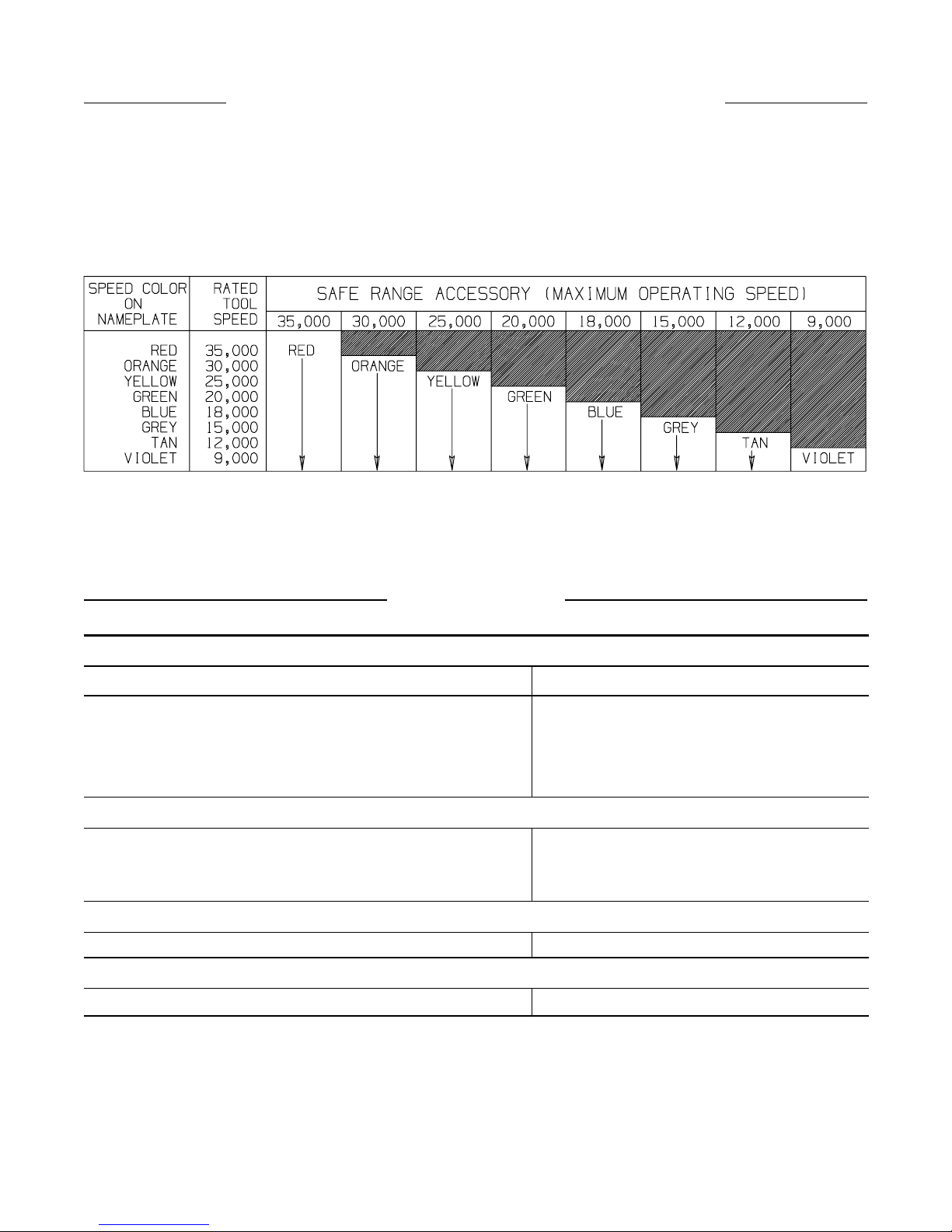
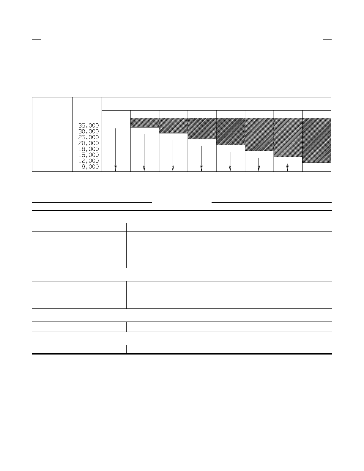
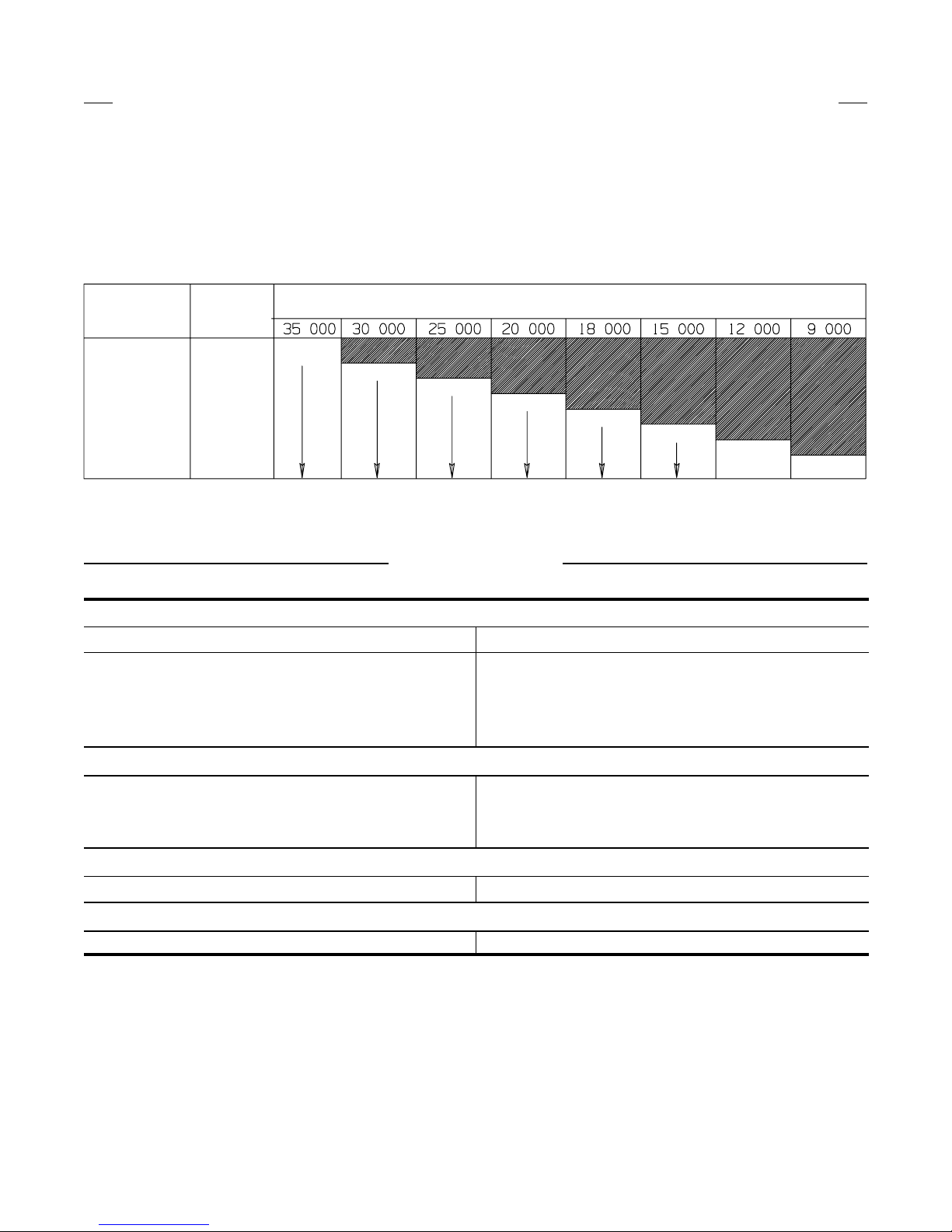
NEW GRINDER TO ACCESSORY COLOR MATCHING GUIDE
Ingersoll–Rand has pioneered a new color code system
designed to:
1. Simplify the identification of rated tool speed via a
unique corresponding color match.
2. Easily communicate the appropriate backing pads and
(READ FROM LEFT TO RIGHT)
accessories for each tool through a matching color
code system on the backing pads and/or other
corresponding Grinder accessories.
3. The chart below demonstrates the color code system
between the Grinder and the accessory.
(Dwg. TPD1146–1)
SPÉCIFICATIONS
1/4” COLLET
Model Speed/rpm
TD250RG4 25,000
TD200RG4 20,000
TD180RG4 18,000
TD120RG4 12,000
1/4” COLLET
TX250RG4 25,000
TX180RG4 18,000
TX120RG4 12,000
3” WHEEL GUARD
TX180RH63 18,000
3” WHEEL GUARD
TXD180RH63 18,000
5
Page 6

F
REV.000
MANUEL D’EXPLOITATION ET
TPD1430
D’ENTRETIEN DES MEULEUSES
DES SÉRIES TD, TX ET TXD
NOTE
Les meuleuses des Séries TD, TX et TXD sont destinées aux travaux dans des espaces restreints dans
l’industrie de fabrication, les chantiers navals, la fabrication de tuyauteries, la fabrication de matrices et
les applications à espace limités. En particulier, elles sont idéales dans les endroits où les tubes,
tuyauteries, gaines, etc. passent à travers des cloisons ou des châssis. Ces petites meuleuses d’angle
sont très efficaces pour le meulage des cordons de soudure lorsqu’une bonne finition est requise.
Ingersoll–Rand ne peut être tenu responsable de la modification des outils par le client pour les adapter à
des applications qui n’ont pas été approuvées par Ingersoll–Rand.
ATTENTION
D’IMPORTANTES INFORMATIONS DE SECURITÉ SONT JOINTES.
LIRE CE MANUEL AVANT D’UTILISER L’OUTIL.
L’EMPLOYEUR EST TENU À COMMUNIQUER LES INFORMATIONS
DE CE MANUEL AUX EMPLOYÉS UTILISANT CET OUTIL.
LE NON RESPECT DES AVERTISSEMENTS SUIVANTS PEUT CAUSER DES BLESSURES
MISE EN SERVICE DE L’OUTIL
S Toujours exploiter, inspecter et entretenir cet outil
conformément au Code de sécurité des outils
pneumatiques portatifs de l’American National
Standards Institute (ANSI B186.1).
• Pour la sécurité, les performances optimales et la
durabilité maximale des pièces, cet outil doit être
connecté à une alimentation d’air comprimé de
6,2 bar (620 kPa) maximum à l’entrée, avec un flexible
de 10 mm de diamètre intérieur.
• Couper toujours l’alimentation d’air comprimé et
débrancher le flexible d’alimentation avant d’installer,
déposer ou ajuster tout accessoire sur cet outil, ou
d’entreprendre une opération d’entretien quelconque
sur l’outil.
• Ne pas utiliser des flexibles ou des raccords
endommagés, effilochés ou détériorés.
• S’assurer que tous les flexibles et les raccords sont
correctement dimensionnés et bien serrés. Voir Plan
TPD905–1 pour un exemple type d’agencement des
tuyauteries.
• Utiliser toujours de l’air sec et propre à une pression
maximum de 6,2 bar. La poussière, les fumées
corrosives et/ou une humidité excessive peuvent
endommager le moteur d’un outil pneumatique.
• Ne jamais lubrifier les outils avec des liquides
inflammables ou volatiles tels que le kérosène, le gasol
ou le carburant d’aviation.
• Ne retirer aucune étiquette. Remplacer touteétiquette
endommagée.
UTILISATION DE L’OUTIL
• Porter toujours des lunettes de protection pendant
l’utilisation et l’entretien de cet outil.
• Porter toujours une protection acoustique pendant
l’utilisation de cet outil.
• Tenir les mains, les vêtements flous et les cheveux
longs, éloignés de l’extrémité rotative de l’outil.
• Prévoir, et ne pas oublier, que tout outil motorisé est
susceptible d’à–coups brusques lors de sa mise en
marche et pendant son utilisation.
• Garder une position équilibrée et ferme. Ne pas se
pencher trop en avant pendant l’utilisation de cet
outil. Des couples de réaction élevés peuvent se
produire à, ou en dessous, de la pression d’air
recommandée.
• La rotation des accessoires de l’outil peut continuer
pendant un certain temps après le relâchement de la
gâchette.
• Les outils pneumatiques peuvent vibrer pendant
l’exploitation. Les vibrations, les mouvements
répétitifs et les positions inconfortables peuvent causer
des douleurs dans les mains et les bras. N’utiliser plus
d’outils en cas d’inconfort, de picotements ou de
douleurs. Consulter un médecin avant de
recommencer à utiliser l’outil.
• Utiliser les accessoires recommandés par
Ingersoll-Rand.
• Cet outil n’est pas conçu pour fonctionner dans des
atmosphères explosives,
• Cet outil n’est pas isolé contre les chocs électriques,
L’utilisation de rechanges autres que les pièces d’origine Ingersoll–Rand peut causer des risques d’insécurité, réduire les
performances de l’outil et augmenter l’entretien, et peut annuler toutes les garanties.
Les réparations ne doivent être effectues que par des réparateurs qualifiés autorisés. Consultez votre Centre de Service
Ingersoll–Rand le plus proche.
Adressez toutes vos communications au Bureau
Ingersoll–Rand ou distributeur le plus proche.
Ingersoll–Rand Company 1999
Imprimé aux É.U.
NOTE
Page 7
SIGNIFICATION DES ETIQUETTES D’AVERTISSEMENT
REV.000
ATTENTION
LE NON RESPECT DES AVERTISSEMENTS SUIVANTS PEUT CAUSER DES BLESSURES
ATTENTION ATTENTION
Porter toujours des lunettes
de protection pendant
l’utilisation et l’entretien de
cet outil.
Porter toujours une
protection acoustique
pendant l’utilisation de cet
outil.
ATTENTION
Les outils pneumatiques
peuvent vibrer pendant
l’exploitation. Les vibrations,
les mouvements répétitifs et les
positions inconfortables
peuvent causer des douleurs
dans les mains et les bras.
N’utiliser plus d’outils en cas
d’inconfort, de picotements ou
de douleurs. Consulter un
médecin avant de recommencer
à utiliser l’outil.
ATTENTION
Garder une position équilibrée et
ferme. Ne pas se pencher trop
en avant pendant
l’utilisation de cet outil.
90 psig
(6.2bar/620kPa)
Ne pas transporter l’outil
par son flexible.
Utiliser de l’air comprimé
à une pression maximum
de 6,2 bar (620 kPa).
ATTENTION
ATTENTION
ATTENTION
Couper toujours l’alimentation
d’air comprimé et débrancher le
flexible d’alimentation avant
d’installer, déposer ou ajuster
tout accessoire sur cet outil, ou
d’entreprendre une opération
d’entretien quelconque sur l’outil.
ATTENTION
Ne pas utiliser des flexibles ou
des raccords endommageés,
effilochés ou détériorés.
AVERTISSEMENTS SPECIFIQUES AUX MEULEUSES
ATTENTION
LE NON RESPECT DES AVERTISSEMENTS SUIVANTS PEUT CAUSER DES BLESSURES
• Ne pas utiliser cet outil si la vitesse à vide réelle
dépasse celle indiquée sur la plaque signalétique.
• Avant de monter une meule, après toute réparation de
l’outil ou avant de fournir une meuleuse pour
utilisation, vérifier la vitesse à vide de la meuleuse
avec un tachymètre pour s’assurer que la vitesse réelle
à 6,2 bar (620 kPa) ne dépasse pas celle poinçonnée ou
imprimée sur la plaque signalétique. Les meuleuses
sorties sur chantier doivent être vérifiées de la même
façon au moins une fois par poste.
• Utiliser toujours le protège–meule Ingersoll–Rand
fourni avec la meuleuse.
• Ne jamais utiliser une meule, une fraise ou tout autre
accessoire ayant une vitesse de service inférieure à la
vitesse à vide de la meuleuse sur laquelle il est monté.
Respecter toujours la vitesse maximum inscrite sur les
disques en papier de la meule.
• Inspecter toutes les meules avant de les monter pour
vérifier qu’elles ne présentent pas d’éclats ou de
fissures. Ne jamais utiliser une meule écaillée, fissurée
ou ayant un endommagement quelconque. Ne jamais
utiliser une meule qui a été trempée dans l’eau ou tout
autre liquide.
• S’assurer que la meule se monte correctement sur
l’arbre. Ne pas utiliser de bagues réductrices, à moins
que ces bagues soient recommandées et fournies par le
fabricant de la meule.
• Après avoir monté une nouvelle meule, tenir la
meuleuse sous un établi en acier ou dans une pièce
coulée et la faire tourner pendant au moins 60
secondes. S’assurer que personne ne se tient dans le
plan de rotation de la meule. Toute meule défectueuse,
mal montée ou de dimension et vitesse incorrectes se
cassera généralement à ce moment là.
• Pour commencer le travail avec une meule froide,
l’appliquer lentement contre la pièce jusqu’à ce que la
meule s’échauffe progressivement. Mettre la meule en
contact avec la pièce en douceur en évitant tout choc
ou pression excessive.
• Remplacer toujours un protège–meule endommagé,
tordu ou très usé. Ne pas utiliser un protège–meule qui
a été soumis à la rupture d’une meule.
• S’assurer que les flasques de meule couvrent au moins
1/3 du diamètre de la meule, et qu’ils sont exempts
d’entailles, de bavures et d’arêtes vives. Utiliser
toujours les flasques fournis par le fabricant; ne
jamais utiliser de flasque de provenance douteuse ou
de rondelle plate. Serrer fermement l’écrou du
flasque.
• L’ouverture du protège–meule doit être orientée côté
opposé à l’opérateur. Le bas de la meule ne doit pas
dépasser le protège–meule.
• Les meuleuses de la Série TD120 ont une vitesse à vide
de 12.000 tr/mn; les meuleuses des Séries TD180,
TX180 et TXD180 ont une vitesse à vide de 18.000
tr/mn; Les meuleuses des Séries TD200 et TX200 ont
une vitesse à vide de 25.000 tr/mn lorsqu’exploitées
avec une pression d’air de 6,2 bar (620 kPa).
L’exploitation à une pression supérieure produira une
vitesse excessive.
• Toujours choisir une pince adaptée à la dimension de
la queue de l’accessoire.
7
Page 8
AVERTISSEMENTS SPECIFIQUES AUX MEULEUSES
REV.000
• Toujours choisir une pince adaptée à la dimension de
la queue de l’accessoire.
• La queue de l’outil doit toujours être insérée dans la
pince sur au moins 10 mm. Serrer fermement l’écrou
de pince pour éviter tout desserrage de l’accessoire
l’écrou de pince avant de mettre la meuleuse en
marche. Ne jamais oublier que la vitesse admissible
d’une meule sur tige doit être réduite lorsque la
longueur de la tige entre le bout de la pince et la meule
(porte–à–faux) est augmentée.
pendant l’emploi de la meuleuse. Vérifier le serrage de
ATTENTION:Une mauvaise combinaison de roue d’affûtage, de protection de roue et de vitesse de l’outil peut provoquer un
accident corporel. Les combinaisons correctes sont spécifiées ci–dessous:
Référence de la
protection
Type de roue Diamètre de roue
mm (po.)
Epaisseru maximale
de roue
Vitesse maximale
(t/min)
mm (po.)
LE2–931 1 3 (76) 1/2 (12,7) 20 500
MISE EN SERVICE DE L’OUTIL
LUBRIFICATION
Ingersoll–Rand No. 10 Ingersoll–Rand No. 68
Ingersoll–Rand No. 50
Utiliser toujours un lubrificateur avec ces outils. Nous
recommandons l’emploi du filtre–régulateur–lubrificateur
suivant :
É. U. – N
o
. C28–04–FKG0–28
Toutes les deux heures de fonctionnement, si un
lubrificateur de ligne n’est pas utilisé, injecter 1/2 à 1 cm
3
d’huile Ingersoll–Rand No. 10 dans le raccord d’admission.
AVERTISSEMENT
Ne pas marquer les codes d’identification client sur les
surfaces non métalliques de cet outil. De telles actions
pourraient affecter les performances de l’outil.
VERS LE
RÉSEAU D’AIR
COMPRIMÉ
VERS
L’OUTIL
PNEU-
MATIQUE
LUBRIFICATEUR
RÉGULATEUR
LIGNE SECONDAIRE AU
MOINS 2 FOIS LA DIMEN-
SION DE L’ADMISSION
D’AIR DE L’OUTIL
VIDANGER
RÉGULIÈREMENT
TUYAUTERIE PRINCIPALE AU
MOINS 3 FOIS LA DIMENSION DE
L’ADMISSION D’AIR DE L’OUTIL
FILTRE
COMPRESSEUR
(Plan TPD905–1)
MONTAGE DE L’ACCESSOIRE
DE DEFONÇAGE
Pour monter l’accessoire de défonçage TD–RK4 ou TD–RK6
sur une meuleuse TD200 ou TD250 équipée d’une pince,
procéder comme suit:
1. Empêcher la rotation du corps de pince à l’aide de la clé
de corps de pince et utiliser la clé de pince pour dévisser
et déposer l’ensemble d’écrou de pince de la meuleuse.
Déposer la pince.
2. Serrer l’outil dans un étau équipé de mordaches en cuir
ou en cuivre, broche vers le haut, et à l’aide d’une clé de
1–1/2”, dévisser et déposer l’écrou d’accouplement.
L’écrou est fileté à gauche, et doit être tourné dans le sens
des aiguilles d’une montre pour le déposer.
3. Déposer l’entretoise d’accouplement et monter
l’entretoise de l’accessoire de défonçage.
4. Visser l’écrou d’accouplement sur le corps et le serrer à
un couple de 27 à 34 Nm. L’écrou est fileté à gauche, et
doit être tourné dans le sens contraire des aiguilles d’une
montre pour le serrer.
5. Insérer la pince dans le corps de pince et visser à la main
l’écrou de pince sur le corps de pince. Monter une fraise
dans la pince et serrer l’écrou de pince.
6. Installer l’adaptateur de nez sur l’ensemble fraise/pince et
le visser sur l’entretoise d’accouplement. Serrer
l’adaptateur à un couple de 2,7 à 4,0 Nm. L’écrou est
fileté à gauche, donc l’adaptateur doit être tourné dans le
sens contraire des aiguilles d’une montre pour le serrer.
7. Monter la vis de verrouillage de l’adaptateur dans
l’adaptateur et la serrer à un couple de 1,3 à 2,0 Nm.
8. Visser l’écrou de verrouillage sur l’adaptateur de nez.
9. Visser l’ensemble de nez sur l’adaptateur et ramener
l’écrou de verrouillage contre l’ensemble. Serrer l’écrou à
un couple de 19,0 à 25,8 Nm.
10. Si un guide de fraisage est utilisé, visser le guide dans
l’ensemble de nez et le serrer à un couple de 4,1 à 5,
4 Nm.
8
Page 9
MISE EN SERVICE DE L’OUTIL
REV.000
GUIDE DE FRAISAGE
DESAXAGE
Dimensions du guide de fraisage
(Plan TPD1208)
NUMERO DE REFERENCE POUR LA
A B C D E
COMMANDE
R120–128–2 (pour tige de 1/4”) 1–1/2 3/8 3/8 1/8 1/2–20NF
R120–128–7 (pour tige de 1/4”)2–1/2 1/2 1/2 3/16 1/2–20NF
LG2–129–1 (pour tige de 3/8”) 2–1/2 1/2 5/8 1/8 5/8–18UNF
K NB: Décalage = 1/2 (dimension ”B” moins diamètre de la fraise)
Les équipements suivants sont disponibles contre supplément et doivent être commandés séparément:
1. Accessoire de défonçage
pour modèles utilisant des fraises de 1/4” de diamètre Réf. TD–RK4. . . . . . . . . . . . . . . . . . . . . . . . . . . . . . . .
pour modèles utilisant des fraises de 3/8” de diamètre Réf. TD–RK6. . . . . . . . . . . . . . . . . . . . . . . . . . . . . . . .
2. Guide de fraisage (pour accessoires de défonçage)
(pour tige de 1/4”)Réf. R120–128–2. . . . . . . . . . . . . . . . . . . . . . . . . . . . . . . . . . . . . . . . . . . . . . . . . . . . . . . . . . . .
(pour tige de 1/4”)Réf. R120–128–7. . . . . . . . . . . . . . . . . . . . . . . . . . . . . . . . . . . . . . . . . . . . . . . . . . . . . . . . . . . .
(pour tige de 3/8”)Réf. LG2–129–1. . . . . . . . . . . . . . . . . . . . . . . . . . . . . . . . . . . . . . . . . . . . . . . . . . . . . . . . . . . .
NOTE
T ous les modèles listés Page 5 peuvent être modifiés pour un échappement avant en inversant la bague de débit et en alignant les
repères sur la lettre “F” du corps. Pour commander un outil à échappement avant à l’usine, remplacer la lettre “R” par la lettre
“F” dans les modèles ci–dessus. Exemple: le modèle à échappement arrière TD12RG4 devient le modèle à échappement avant
TD120FG4.
9
Page 10
MISE EN SERVICE DE L’OUTIL
REV.000
NOUVEAU GUIDE DE CORRESPONDANCE MEULEUSE/ACCESSOIRE À CODE COULEUR
Ingersoll–Rand a lancé un nouveau système de code couleur
destiné à:
1. Simplifier l’identification des vitesses nominales des
outils grâce à un code couleur de correspondance unique.
2. Faire correspondre facilement les plateaux–supports et les
(A LIRE DE GAUCHE A DROITE)
COULEUR
DE VITESSE
SUR PLAQUE
SIGNALETIQUE
ROUGE
ORANGE
JAUNE
VERT
BLEU
GRIS
OCRE
VIOLET
VITESSE
NOMINALE
DE
L’OUTIL
GAMME SURE DES ACCESSOIRES (VITESSE MAXIMALE DE FONCTIONNMENT)
35 000 30 000 25 000 20 000 18 000 15 000 12 000 9 000
ROUGE
ORANGE
JAUNE
SPÉCIFICATIONS
1/4” PINCE
accessoires à chaque outil grâce à l’introduction d’un
code couleur d’identification sur les plateaux et/ou les
accessoires des meuleuses.
3. Le tableau ci–dessous illustre le système d’identification
couleur pour les meuleuses et les accessoires.
VERT
BLEU
GRIS
OCRE
VIOLET
(Plan TPD1146–1)
Modèle Vitesse d’exploitation maximum
TD250RG4
TD200RG4
TD200RG4
TD120RG4
25.000
20.000
18.000
12.000
1/4” PINCE
TX250RG4
TX180RG4
TX120RG4
25.000
18.000
12.000
3” PROTÈGE–MEULE
TX180RH63 18.000
3” PROTÈGE–MEULE
TXD180RH63 18.000
10
Page 11
E
REV.000
MANAL DE USO Y MANTENIMIENTO
TPD1430
PARA AMOLADORAS
MODELOS TD, TX Y TXD
NOTA
Las Amoladoras Serie TD, TX y TXD están diseñadas para trabajo a distancia mínima en la industria de
fabricación de metales, astilleros, fabricación de tuberías y aplicaciones en espacios reducidos. Estas
amoladoras resultan especialmente eficaces para aquellas situaciones en las que los conductos,
tuberías, etc. atraviesan tabiques o bastidores. Estas pequeñas Amoladoras son muy eficaces para
amolar cordones de soldadura y obtener un acabado fino.
Ingersoll–Rand no aceptará responsabilidad alguna por la modificación de las herramientas efectuada
por el cliente para las aplicaciones que no hayan sido consultadas con Ingersoll–Rand.
AVISO
SE ADJUNTA INFORMACIÓN IMPORTANTE DE SEGURIDAD.
LEA ESTE MANUAL ANTES DE USAR LA HERRAMIENTA.
ES RESPONSABILIDAD DE LA EMPRESA ASEGURARSE DE QUE EL OPERARIO
ESTÉ AL TANTO DE LA INFORMACIÓN QUE CONTIENE ESTE MANUAL.
EL HACER CASO OMISO DE LOS AVISOS SIGUIENTES PODRÍA OCASIONAR LESIONES
PARA PONER LA HERRAMIENTA EN SERVICIO
S Utilice, examine y mantenga siempre esta herramienta
conforme al código de seguridad para herramientas
neumáticas portátiles de la American National
Standards Institute (ANSI B186.1).
• Para seguridad, máximo rendimiento y vida de
servicio de las piezas, use esta herramienta a una
presión de aire máxima de 90 psig (6,2 bar/620 kPa)
en la manguera de suministro de aire con diámetro
interno de 10 mm.
• Corte siempre el suministro de aire y desconecte la
manguera de suministro de aire antes de instalar,
desmontar o ajustar cualquier accesorio de esta
herramienta, o antes de realizar cualquier operación
de mantenimiento de la misma.
• No utilice mangueras de aire y accesorios dañados,
desgastados ni deteriorados.
• Asegúrese de que todas las mangueras y accesorios
sean del tamaño correcto y estén bien apretados. Vea
Esq. TPD905–1 para un típico arreglo de tuberías.
• Use siempre aire limpio y seco a una presión máxima
de 90 psig. El polvo, los gases corrosivos y/o el exceso
de humedad podrían estropear el motor de una
herramienta neumática.
• No lubrique las herramientas con líquidos inflamables
o volátiles tales como queroseno, gasoil o combustible
para motores a reacción.
• No saque ninguna etiqueta. Sustituya toda etiqueta
dañada.
USO DE LA HERRAMIENTA
• Use siempre protección ocular cuando maneje, o
realice operaciones de mantenimiento en esta
herramienta.
• Use siempre protección para los oídos cuando maneje
esta herramienta.
• Mantenga las manos, la ropa suelta y el cabello largo
alejados del extremo giratorio de la herramienta.
• Anticipe y esté alerta sobre los cambios repentinos en
el movimiento durante la puesta en marcha y el
manejo de toda herramienta motorizada.
• Mantenga una postura de cuerpo equilibrada y firme.
No estire demasiado los brazos al manejar la
herramienta. Pueden ocurrir reacciones de alto par a,
o a menos de, la recomendada presión de aire.
• Los accesorios de la herramienta podrían seguir
girando brevemente después de haber soltado la
palanca de estrangulación.
• Las herramientas neumáticas pueden vibrar durante
el uso. La vibración, repetición o posiciones incómodas
pueden dañarle los brazos y manos. En caso de
incomodidad, sensación de hormigueo o dolor, deje de
usar la herramienta. Consulte a un médico antes de
volver a usarla otra vez.
• Utilice únicamente los accesorios Ingersoll–Rand
recomendados.
• Esta herramienta no ha sido diseñada para trabajar
en ambientes explosivos.
• Esta herramienta no está aislada contra descargas
eléctricas.
NOTA
El uso de piezas de recambio que no sean las auténticas piezas Ingersoll–Rand podría poner en peligro la seguridad, r educir el
rendimiento de la herramienta y aumentar los cuidados de mantenimiento necesarios, así como invalidar toda garantía.
Las reparaciones sólo serán realizadas por personal cualificado y autorizado. Consulte con el centro de servicio Ingersoll–Rand
autorizado más próximo.
Toda comunicación se deberá dirigir a la oficina o
al distribuidor Ingersoll–Rand más próximo.
Ingersoll–Rand Company 1999
Impreso en EE. UU.
Page 12
ETIQUETAS DE AVISO
REV.000
AVISO
EL HACER CASO OMISO DE LOS AVISOS SIGUIENTES PODRÍA OCASIONAR LESIONES.
ADVERTENCIA
Use siempre protección ocular
cuando utilice esta herramienta
o realice operaciones de
mantenimiento en la misma.
ADVERTENCIA
Las herramientas neumáticas
pueden vibrar durante el uso.
La vibración, los movimientos
repetitivos o las posiciones
incómodas podrían dañarle los
brazos y las manos. En caso
de incomodidad, sensación de
hormigueo o dolor, dejar de
usar la herramienta. Consultar
al médico antes de volver a utilizarla.
ADVERTENCIA
Mantener una postura del cuerpo
equilibrada y firme. No estirar demasiado los brazos al manejar la
herramienta.
90 psig
(6.2bar/620kPa)
ADVERTENCIA
Use siempre protección para
los oídos cuando utilice esta
herramienta.
ADVERTENCIA
No coger la herramienta
por la manguera para levantarla.
ADVERTENCIA
Manejar la herramienta a una
presión de aire máxima de 90
psig (6,2 bar/620 kPa).
ADVERTENCIA
Cortar siempre el suministro
de aire y desconectar la manguera de suministro de aire
antes de instalar, retirar o ajustar cualquier accesorio de esta
herramienta, o antes de realizar
cualquier operación de mantenimiento de la misma.
ADVERTENCIA
No utilizar mangueras de aire
y accesorios dañados, desgastados ni deteriorados.
AVISOS ESPECIFICOS PARA AMOLADORA
AVISO
EL HACER CASO OMISO DE LOS AVISOS SIGUIENTES PODRÍA OCASIONAR LESIONES.
• No use esta herramienta si la velocidad libre real
excede la indicada en la placa de identificación.
• Antes de montar una muela, y después de todas las
reparaciones de herramienta y siempre que se
proporcione una Amoladora para su uso, compruebe
la velocidad libre de dicha Amoladora con un
tacómetro para asegurarse que su velocidad real a
90 psig (620 bar/6,2 kPa) no exceda las rpm
estampadas o impresas en la placa de identificación.
Las Amoladoras usadas en trabajos deberán ser
examinadas similarmente como mínimo una vez en
cada jornada de trabajo.
• Use siempre el Cubremuela Ingersoll–Rand
recomendado y suministrado con la Amoladora.
• No use nunca una muela, taladro rotatorio dental o
cualquier otro accesorio que tenga una velocidad
máxima de funcionamiento menor que la velocidad
libre de la Amoladora en la que se esté usando.
Cumpla siempre las rpm máximas indicadas en los
distanciadores de la muela.
• Inspeccione todas las muelas antes de su montaje para
ver si tienen grietas o roturas. No use una muela que
esté rota o agrietada o dañada de cualquier otra
forma. No use una muela que haya estado a remojo en
agua o en cualquier otro líquido.
• Asegúrese de que la muela esté bien puesta en la
espiga. No use anillos reductores para adaptar una
muela a la espiga a menos que estos hayan sido
suministrados y recomendados por el fabricante de
muelas.
• Después de haber montado una muela nueva, sujete la
Amoladora bajo un banco de acero o en un molde y
hágala funcionar durante 60 segundos como mínimo.
Asegúrese que no haya nadie en el entorno de
operación de muela. Si la muela es defectuosa, está
mal montada o es del tamaño y velocidad incorrectas,
normalmente fallará en este momento.
• Cuando ponga en marcha una muela en frío, aplíquela
lentamente al trabajo hasta que se caliente
gradualmente. Contacte la zona de trabajo
suavemente, y evite golpes o exceso de presión.
• Cambie siempre un cubremuela dañado, torcido o
muy desgastado. No use un cubremuela que haya
experimentado un fallo de muela.
• Asegúrese que las bridas de muela sean de un
diámetro mínimo de 1/3 de la muela y que estén libres
de marcas, abrasiones y bordes afilados. Use siempre
las bridas de muela suministradas por el fabricante;
no use nunca una brida casera o arandela normal.
Apriete la Tuerca de Brida de manera segura.
• La apertura del cubremuela deberá estar orientada
hacia afuera del operario. La parte inferior de la
muela no deberá proyectarse fuera del cubremuela.
• Las Amoladoras Modelos TD120 tienen una velocidad
libre de 12.000 rpm; Las Amoladoras Modelos TD180,
TX180 y TXD180 tienen una velocidad libre de 18.000
rpm; Las Amoladoras Modelos TD200 y TX200 tienen
una velocidad libre de 25.000 rpm cuando se operan a
una presión de aire máxima de 90 psig (6,2 bar/
620 kPa). Si se utiliza la herramienta a una presión de
aire comprimido mayor, se causará exceso de
velocidad.
• Empareje siempre el tamaño de pinza con el tamaño
de vástago de accesorio. ( continuación)
12
Page 13
AVISOS ESPECÍFICOS PARA AMOLADORA
REV.000
• Inserte siempre el vástago de herramienta en la pinza
un mínimo de 10 mm. Apriete la Tuerca de Pinza de
manera segura para evitar que se salga el accesorio
durante el funcionamiento de la Amoladora.
usar la Amoladora. Preste especial atención al hecho
de que la velocidad permitida de un punto de montaje
disminuye cuando se incrementa la longitud de eje
entre extremo de pinza y punto de montaje (saliente).
Compruebe el apriete de Tuerca de Pinza antes de
AVISO: Combinaciones incorrectas de rueda de rectificación, protector de rueda y velocidad de herramienta puedan
resultar en lesionamientos. Las combinaciones correctas se especifican a continuación:
Número de Pieza del
Protector
Tipo de Rueda Diámetro de Rueda
mm (in.)
Grosor Máximo de
Rueda
Velocidad Máxima
(rpm)
mm (in.)
LE2–931 1 3 (76) 1/2 (12,7) 20 500
PARA PONER LA HERRAMIENTA EN SERVICIO
LUBRICACIÓN
Ingersoll–Rand N º 10 Ingersoll–Rand Nº 68
Ingersoll–Rand Nº 50
Utilice siempre un lubricador de aire comprimido con estas
herramientas. Recomendamos la siguiente unidad de
Filtro–Lubricador–Regulador:
EE.UU. – Nº. C28–04–FKG0–28
Después de cada dos horas de uso, a menos que se use un
lubricante de línea de aire comprimido, inyecte 1\2 – 1 cc de
Aceite Ingersoll–Rand Nº 10 en la Admisón de Aire.
PRECAUCIÓN
No marque ninguna superficie no metálica de esta
herramienta con los códigos de identificación de cliente.
Tal acción podría afectar al rendimiento de la
herramienta.
TUBERÍAS PRINCIPALES 3
VECES EL TAMAÑO DE
ENTRADA DE HERRAMIENTA
NEUMÁTICO
A LA
HERRA–
MIENTA
NEUMÁTICA
LUBRICADOR
TUBERÍA DE RAMAL
2 VECES EL TAMAÑO
DE ENTRADA DE
HERRAMIENTA
NEUMÁTICA
PURGAR
PERIÓDICAMENTE
NEUMÁTICAAL SISTEMA
REGULADOR
FILTRO
COMPRESOR
(Esq. TPD905–1)
MONTAJE DEL ACCESORIO DE
FRESADO
Para montar un accesorio de fresado TD–RK4 o TD–RK6 a
una Amoladora TD200 o TD250 con pinza, proceda de la
manera siguiente:
1. Utilice la llave de cuerpo de pinza para evitar que gire el
cuerpo de pinza y, utilizando una llave de tuerca de pinza,
desenrosque y quite el conjunto de tuerca de pinza de la
amoladora. Saque la pinza.
2. Sujete la herramienta en un tornillo de banco con
mordazas cubiertas de cobre o cuero con el husillo hacia
arriba y, utilizando una llave de 1–1/2 pulg., desatornille
la tuerca de abrazadera. Puesto que se trata de una rosca
hacia la izquierda, gire la tuerca en el sentido de las
agujas del reloj para quitarla.
3. Saque el espaciador de abrazadera e instale el espaciador
de abrazadera del accesorio de fresado.
4. Enrosque la tuerca de abrazadera en la carcasa y apriete
dicha tuerca entre 20 y 25 ft–lb (27 y 34 Nm) de par.
Puesto que se trata de una rosca hacia la izquierda, gire
la tuerca en sentido contrario al de las agujas del reloj
para quitarla.
5. Inserte la pinza en el cuerpo de pinza y enrosque la tuerca
de pinza en el cuerpo de pinza sin apretarla. Inserte una
broca de fresado en la pinza y apriete la tuerca de pinza.
6. Inserte el adaptador de la pieza de extremo sobre el
conjunto de pinza y broca de fresado, y enrósquelo en el
espaciador de abrazadera. Apriete el adaptador entre 2 y
3 ft–lb ( 2,7 a 4,0 Nm) de par. Puesto que se trata de una
rosca hacia la izquierda, gire el adaptador en sentido
contrario al de las agujas del reloj para quitarlo.
7. Instale el tornillo de bloqueo en el adaptador, y apriételo
entre 12 y 18 pulg.–lb (1,3 a 2,0 Nm) de par.
8. Enrosque la tuerca de bloqueo en el adaptador de la pieza
de extremo.
9. Enrosque el conjunto de pieza de extremo en el adaptador
y gire la tuerca de bloqueo en sentido contrario, contra el
conjunto. Apriete la tuerca de bloqueo entre 14 y 19 ft–lb
( 19,0 a 25,8 Nm) de par.
10. Si se utiliza una guía de recorte, enrosque la guía en la
pieza de extremo y apriete dicha guía entre 3 y 4 ft–lb
(4,1 a 5,4 Nm) de par.
13
Page 14
PARA PONER LA HERRAMIENTA EN SERVICIO
REV.000
GUÍA DE RECORTE
DESCENTRAMIENTO
Dimensiones de la guía de recorte
(Esq. TPD1208)
NUMERO DE PIEZA PARA PEDIDO A B C D E
R120–128–2 (para mango de 1/4 pulg.) 1–1/2 3/8 3/8 1/8 1/2–20NF
R120–128–7 (para mango de 1/4 pulg.) 2–1/2 1/2 1/2 3/16 1/2–20NF
LG2–129–1 (para mango de 3/8 pulg.) 2–1/2 1/2 5/8 1/8 5/8–18UNF
K Nota: Descentramiento = 1/2 (dimensión “B” menos diámetro de broca de recorte.)
El siguiente equipo está disponible a un precio adicional y debe ser pedido por separado:
1. Conjunto de accesorio de fresado
para modelos con broca de 1/4 pulg. de diámetro Pieza Nº. TD–RK4. . . . . . . . . . . . . . . . . . . . . . . . . . . . . . . . . . . .
para modelos con broca de 3/8 pulg. de diámetro Pieza Nº. TD–RK6. . . . . . . . . . . . . . . . . . . . . . . . . . . . . . . . . . . .
2. Guía de recorte (para accesorios de fresado)
para mango de 1/4 pulg. Pieza Nº. R120–128–2. . . . . . . . . . . . . . . . . . . . . . . . . . . . . . . . . . . . . . . . . . . . . . . . . . . . . . . .
para mango de 1/4 pulg. Pieza Nº. R120–128–7. . . . . . . . . . . . . . . . . . . . . . . . . . . . . . . . . . . . . . . . . . . . . . . . . . . . . . . .
para mango de 3/8 pulg. Pieza Nº. LG2–129–1. . . . . . . . . . . . . . . . . . . . . . . . . . . . . . . . . . . . . . . . . . . . . . . . . . . . . . . .
NOTA
Todos los modelos que aparecen listados en la página 5 se pueden convertir en herramientas de escape delantero invirtiendo para
ello el anillo de flujo y alineando las marcas de indicador con la letra “F” que aparece en la carcasa. Para pedir a la fábrica una
herramienta de escape delantero, sustituya la letra “F” por “R” en los modelos mencionados m ás arriba. Ejemplo: el modelo de
escape trasero TD12RG4 se convierte en el modelo de escape delantero TD120FG4.
14
Page 15
PARA PONER LA HERRAMIENTA EN SERVICIO
REV.000
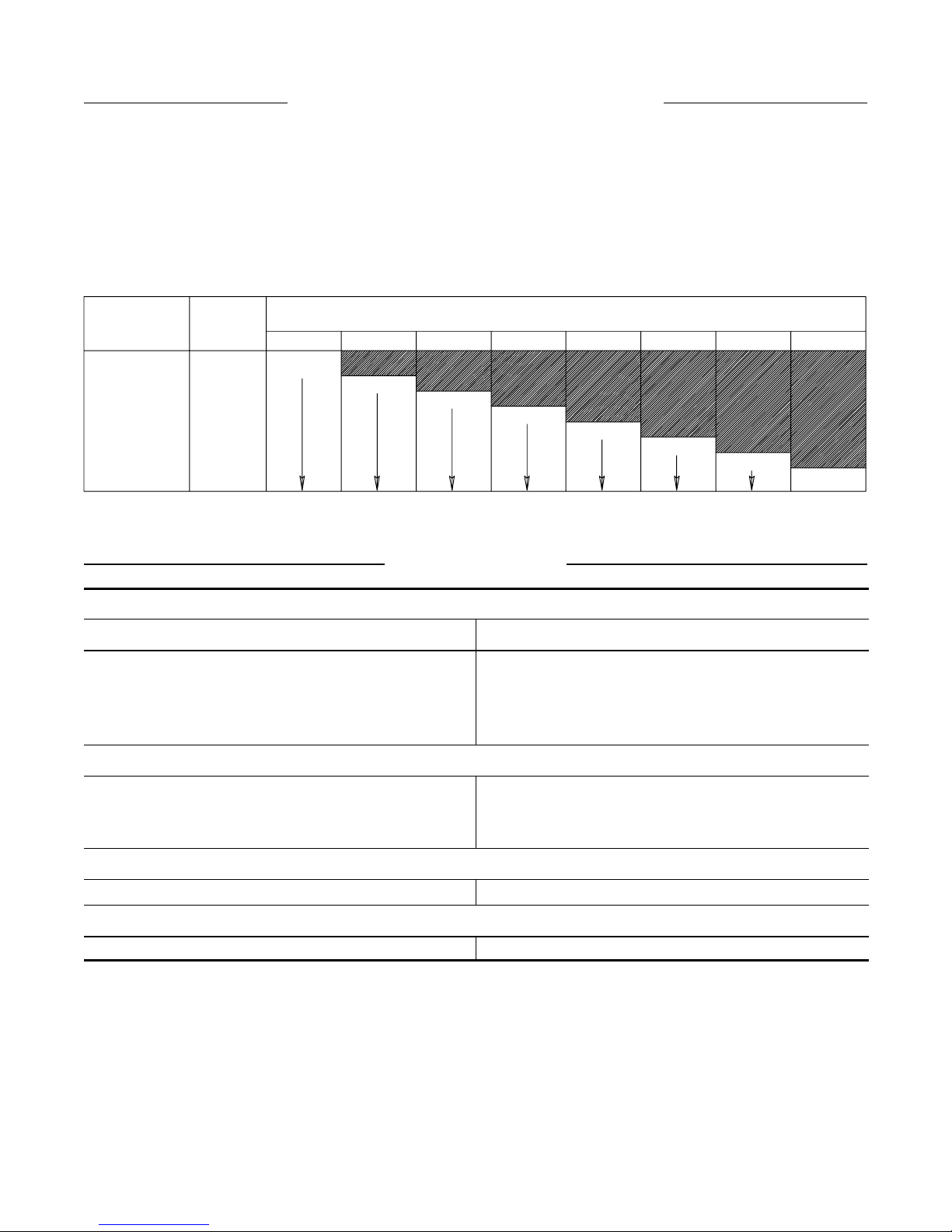
NUEVO SISTEMA DE CÓDIGO DE COLORES
Ingersoll–Rand ha introducido un nuevo sistema de
codificación de colores diseñado para:
1. Simplificar la identificación de la velocidad de
herramienta regulada por una codificación de colores
correspondientes única.
2. Comunicar fácilmente los accesorios y almohadillas de
(LEA DE IZQUIERDA A DERECHA)
COLOR DE
VELOCIDAD EN
PLACA DE
IDENTIFICACION
ROJO
NARANJA
AMARILLO
VERDE
AZUL
GRIS
MARRON
VIOLETA
VELOCIDAD
DE LIMITE DE SEGURIDAD DE
HERRA–
MIENTA
35 000
30 000
25 000
35 000 30 000 20 00025 000 18 000 15 000 12 000 9 000
ROJO
NARANJA
AMARILLO
20 000
18 000
15 000
12 000
9 000
ESPECIFICACIONES
refuerzo correspondientes a cada herramienta gracias a un
sistema de codificación de colores en las almohadillas de
repuesto o/y otros accesorios de Amoladora
correspondientes.
3. La tabla que aparece más abajo muestra el sistema de
codificación de colores entre Amoladora y accesorio.
ACCESORIO (MAXIMA VELOCIDAD DE OPERACION)
VERDE
AZUL
GRIS
MARRON
VIOLETA
(Esq. TPD1146–1)
1/4” PINZA
Modelo Velocidad Libre, rpm
TD250RG4
TD200RG4
TD180RG4
TD120RG4
25.000
20.000
18.000
12.000
1/4” PINZA
TX250RG4
TD180RG4
TD120RG4
25.000
18.000
12.000
CUBREMUELA
TD180RH63 18.000
CUBREMUELA
TXD180RH63 18.000
15
Page 16
P
REV.000
MANUAL DE FUNCIONAMENTO
TPD1430
E MANUTENÇÃO PARA
ESMERILADORAS SÉRIES TD, TX E TXD
AVISO
Esmeriladoras Séries TD, TX e TXD são concebidas para industrias metalomecânicas,
estaleiros navais, industria de tubos, moldes e aeronáutica. Estas pequenas Esmeriladoras são
muito eficientes no esmerilamento de cordão de solda deixando um acabamento fino.
A Ingers oll–Rand não é responsável por modificações, feitas pe lo cliente em ferramentas, nas qua is
a Ingers oll–Rand não tenha sido consultada.
ADVERTÊNCIA
INFORMAÇÃO DE SEGURANÇA IMPORTANTE EM ANEXO
LEIA ESTE MANUAL ANTES DE OPERAR A FERRAMENTA.
É DA RESPONSABILIDADE DO EMPREGADOR COLOCAR A INFORMAÇÃO
DESTE MANUAL NAS MÃOS DO OPERADOR.
O NÃO CUMPRIMENTO DAS SEGUINTES ADVERTÊNCIAS PODE RESULTAR EM FERIMENTOS.
COLOCANDO A FERRAMENTA EM
FUNCIONAMENTO
S Sempre opere, inspeccione e mantenha esta
ferramenta de acordo com o Código de Segurança do
Instituto Americano de Padrões Nacionais para
Ferramentas Pneumáticas Portáteis (ANSI B186.1).
• Para segurança, máximo desempenho e máxima
durabilidade das peças, opere esta ferramenta com uma
pressão de ar máxima de 6,2 bar/620 kPa (90 psig) na
entrada da mangueir a de alimentação de ar com
diâmetro interno de 10 mm (3/8”).
• Desligue sempre a alimentação de ar e desconecte a
mangueira de alimentação de ar antes de instalar,
remover ou ajustar qualquer acess ório nesta ferramenta,
ou antes de executar qualquer serviço de manutenção
nesta ferramenta.
• Não us e mangueiras de ar ou adaptadores danificados,
gastos ou deteriorados.
• Certifiqu e–se de que todas as mangueiras e ada ptado res
sejam do tamanho cor rec to e es te jam apertados com
firmeza. Veja o Desenho TPD905–1 para um arra njo
típico de tubagem.
• Use sempre ar seco e limpo com pressão máxima de
90 psig. Pó, fumos corros ivos e/ou humidade excessiva
podem arruinar o motor de uma ferramenta pneumática.
• Não lubrifique as ferramentas com líquidos inflamáveis
ou voláteis tais como que rose ne , diesel ou combustível de
jactos.
• Não remova nenhum rótulo. Repo nha qualquer rótulo
danificado.
USANDO A FERRAMENTA
• Use sempre óculos de protec ção quando estiv er operando
ou executando serviço de manute nção nesta ferramenta.
• Use sempre protecção contra ruído ao operar esta
ferramenta.
• Mantenha as mãos, pa rtes do vestuário soltas e cabelos
compridos afa s tados da ex tremidade em rotação.
• Antecipe e esteja alerta a mudanças repentinas no
movimento quando ligar e operar qualquer ferramenta
motorizada.
• Mantenha a posição do corpo equilibrada e firme. Não
exagere quando operar esta ferramenta. Torques de
reacção elevados podem ocorrer na ou aba ixo da pres são
de ar recomendada.
• Os acessórios da ferramenta podem continuar a girar
brevemente após a pressão ter sido aliviada.
• Ferramentas accionadas pneumáticamente podem vibrar
em uso. Vibração, movimentos repetitivos ou posições
desconfortáveis podem se r prejudiciais às mãos e aos
braços. Pare de usar a ferramenta caso ocorra algum
desconforto, sensação de formigue iro ou dor. Procure
assistência médica antes de retornar ao trabalho.
• Use acessórios recomendados pela Ingersoll–Rand.
• Esta Ferramenta não foi concebida para trabalhos em
atmosferas explosivas.
• Esta Ferramenta não está isolada contra choques
eléctricos.
O uso de peças de substituição q u e não sejam genuinamente da Ingersoll–Rand podem resultar em riscos de segurança, diminuição
do desempenho da ferramenta, aumento da necessidade de manutenção e pode invalidar toda s as garantias.
As reparações devem ser feitas somente por pe ss oal treinado autoriz ado. Consulte o Centro de Serviços da Ingersoll–Rand mais
próximo.
Envie Todos os Comunicados Para o Distribuidor ou
Escritório da Ingersoll–Rand Mais Próximo.
Ingersoll–Rand Company 1999
Impresso nos E.U.A.
AVISO
Page 17
IDENTIFICAÇÃO DO RÓTULO DE ADVERTÊNCIA
REV.000
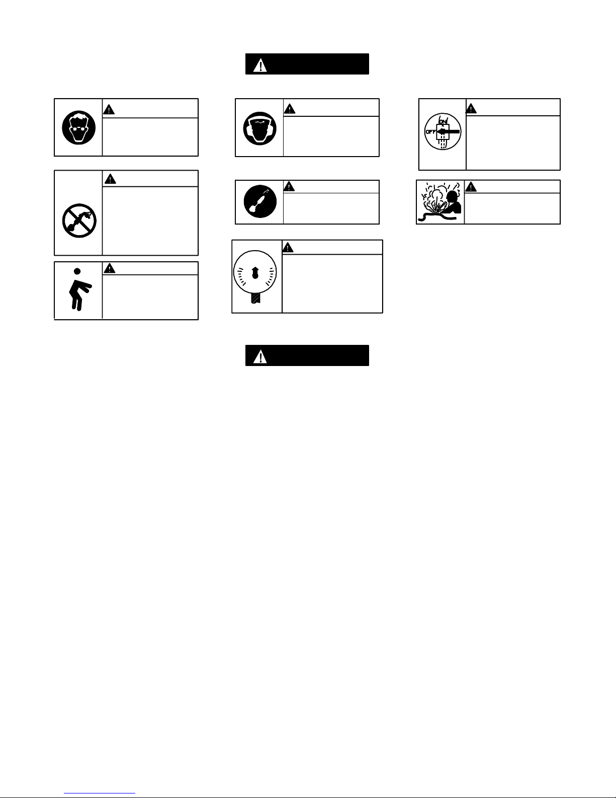
ADVERTÊNCIA
O NÃO CUMPRIMENTO DAS SEGUINTES ADVERTÊNCIAS PODE RESULTAR EM FERIMENTO.
ADVERTÊNCIA
Use sempre óculos de protecção quando estiver ope–
rando ou executando algum
serviço de manutenção nesta ferramenta.
ADVERTÊNCIA
Ferramentas accionadas pneumáticamente podem vibrar em uso. Vibração, movimentos repetitivos ou
posições desconfortáveis podem ser
prejudiciais às mãos e aos braços.
Pare de usar a ferramenta caso
ocorra algum desconforto, sensação de formigueiro ou dor . Procure assistência médica antes de retornar ao trabalho.
ADVERTÊNCIA
Mantenha a posição do corpo
equilibrada e firme. Não exagere quando operar esta ferramenta. Torques de reacção elevados podem ocorrer sob a
pressão de ar recomendada.
90 psig
(6.2bar/620kPa)
ADVERTÊNCIA
Use sempre protecção contra
o ruído ao operar esta ferramenta.
ADVERTÊNCIA
Não carregue a ferramenta
segurando na mangueira.
ADVERTÊNCIA
Opere com pressão do ar Máxima
de 90–100 psig(6,2–6,9bar).
ADVERTÊNCIA
Desligue sempre a alimentação de
ar e desconecte a mangueira de
alimentação de ar antes de instalar, remover ou ajustar qualquer
acessório nesta ferramenta, ou
antes de executar algum serviço
de manutenção nesta ferramenta.
ADVERTÊNCIA
Não use mangueiras de ar ou
adaptadores danificados, gastos
ou deteriorados.
ADVERTÊNCIAS ESPECÍFICAS SOBRE A ESMERILADORA
ADVERTÊNCIA
O NÃO CUMPRIMENTO DAS SEGUINTES ADVERTÊNCIAS PODE RESULTAR EM FERIMENTO.
• Não use esta ferramenta se a velocidade livre total
exceder a rpm indicada na placa de identificação.
• Antes de mo ntar o disco, de pois de qualquer reparação
de ferramenta ou quando se pretende que uma
Esmerilador a se ja colo cada em funcionamento, ver ifique
a velocidade livre da Esmer ilado r a com um tacometro
para se ce r tifica r de que a sua velo c idade real a
6,2 bar/620kPa (90 psig) não exceda a rpm selada ou
impressa n a placa de identificação. As Esmeriladoras em
funcionamento devem ser similarmente verificadas pelo
menos uma ve z em cada turno.
• Use se mpre o Protector do Dis c o da Ingers o ll–Rand
fornecido com a Esmeriladora
• Não use qualquer dis c o de esmerilame nto , broca ou
outro acessório que possua uma velocidade máxima de
operação menor do que a velocidade livre da
Esmerilador a que esteja a se r usada. Res pe ite sempre a
máxima rpm nos adaptadores de disco de
esmerilament o .
• Verifique todas os discos de esmerilamento par a ve r se
há lascas ou rachadur as ante s da montagem. Não use
um disco que esteja las c ado ou rachado ou de alguma
maneira danifica do . Não use um disco que tenha sido
encharcado com água ou qualquer outro líquido.
• Verifique se o disco de esmerilamento se encaix a na
árvore de montagem. Não use rolamentos redutores
para adaptar um disco na árvore de montagem a não
ser que ta is rolamentos tenham sido fornecidos ou
recomendados pe lo fabr ica nte do disco.
• Depois de monta r um novo disco, se gure a Es me rila dor a
sob uma bancada de aço ou dentro de uma moldage m e
coloque–a em funcioname nto por 60 segundos. Verifique
se não há ninguém dentro do plano de operação. Se o
disco estiv er com algum defeito , inadequa dame nte
montado ou se for do tamanho er r ado ou tiver
velocidade incorrecta, este é o momento em que ele
normalmente falha r á.
• Quando iniciar um trabalho com um disco frio, ponha–o
a trabalhar lentamente até que o discor aqueça
gradualmente Faça um contacto suave com o local a ser
trabalhado e evite de executar qualquer ação de
batimento ou pres s ão excessiva.
• Reponha um protector do disc o sempre que estiver
danificado, torto ou severamente gasto. Não use um
protector do disco que tenha sido sujeito a uma falha do
disco.
• Certifiqu e–se de que as flanges da roda sejam pelo
menos 1/3 do diâmetro do disco de esmer ila mento, livre
de cortes, arestas e extremida des afia das . Use sempre
flanges do disc o for nec idas pelo fabricante. Nunca use
uma flange provisória ou uma anilha plana . Aperte bem
a Porca da Flange.
• A abertura do protector de v e estar afa stada do
operador. O fundo do disc o não deve se extender pa r a
fora do protector.
• As Esmeriladoras de Ângulo Séries HA9 0 poss uem uma
velocidade livre de 9.000 rpm e as Séries HA120 e
HXA120 possuem 12.000 rpm, quando opera da s sob
uma pressão de ar de 6,2 bar/620 kPa (9 0 psig).
Operações sob condições de pres s ões mais elevadas
resultarão em velocida des excessiva s .
(continua)
17
Page 18
ADVERTÊNCIAS ESPECÍFICAS SOBRE A ESMERILADORA
REV.000
• Use sempre uma pinça cuja dimensão seja igual ao
encabadouro acessório.
• Insira sempre o encabadouro da ferramenta com
comprimento que não seja inferior a 10mm no colete.
Aperte a Porca do Pinça seguramente para evitar que
o acessório se desajuste durante a operação da
esmeriladora. Verifique o aperto da Porca do Pinça
antes de operar a esmeriladora. Preste particular
atenção ao facto de que a velocidade permitida de um
ponto montado é diminuída quando o comprimento do
eixo é aumentado entre a extremidade da pinça e o
ponto montado. (pendurado)
ADVERTÊNCIA:Combinações incorrectas de disco de esmerilamento, protectordo disco e velocidade da ferramenta pode
resultar em ferimento. As combinações correctas estaõ especificadas abaixo:
Número de Peça do
Protector
Tipo do Disco Diâmetro do Disco
mm (pol.)
Espressura Máxima
do Disco
Velocidade Máxima
rpm
mm (pol.)
LE2–931 1 (3) 76 12,7 (1/2) 20 500
COLOCANDO A FERRAMENTA EM FUNCIONAMENTO
LUBRIFICAÇÃO
Ingersoll–Rand No. 10 Ingersoll–Rand No. 68
Ingersoll–Rand No. 50
Use sempre um lubrificador de ar de linha com estas
ferramentas. Nós recomendamos a seguinte Unidade
Filtro–Lubrificador–Regulador :
E.U.A. – No. C28–04–FKG0–28
Depois de cada duas horas de operação, se estiver usando
um lubrificador de ar de linha, injecte 1/2 a 1 cc de Óleo
Ingersoll–Rand No. 10 na Entrada de Ar.
CUIDADO
Não marque as superfícies não metálicas desta ferramenta
com códigos de identificação do cliente. Tais acções podem
afectar o desempenho da ferramenta.
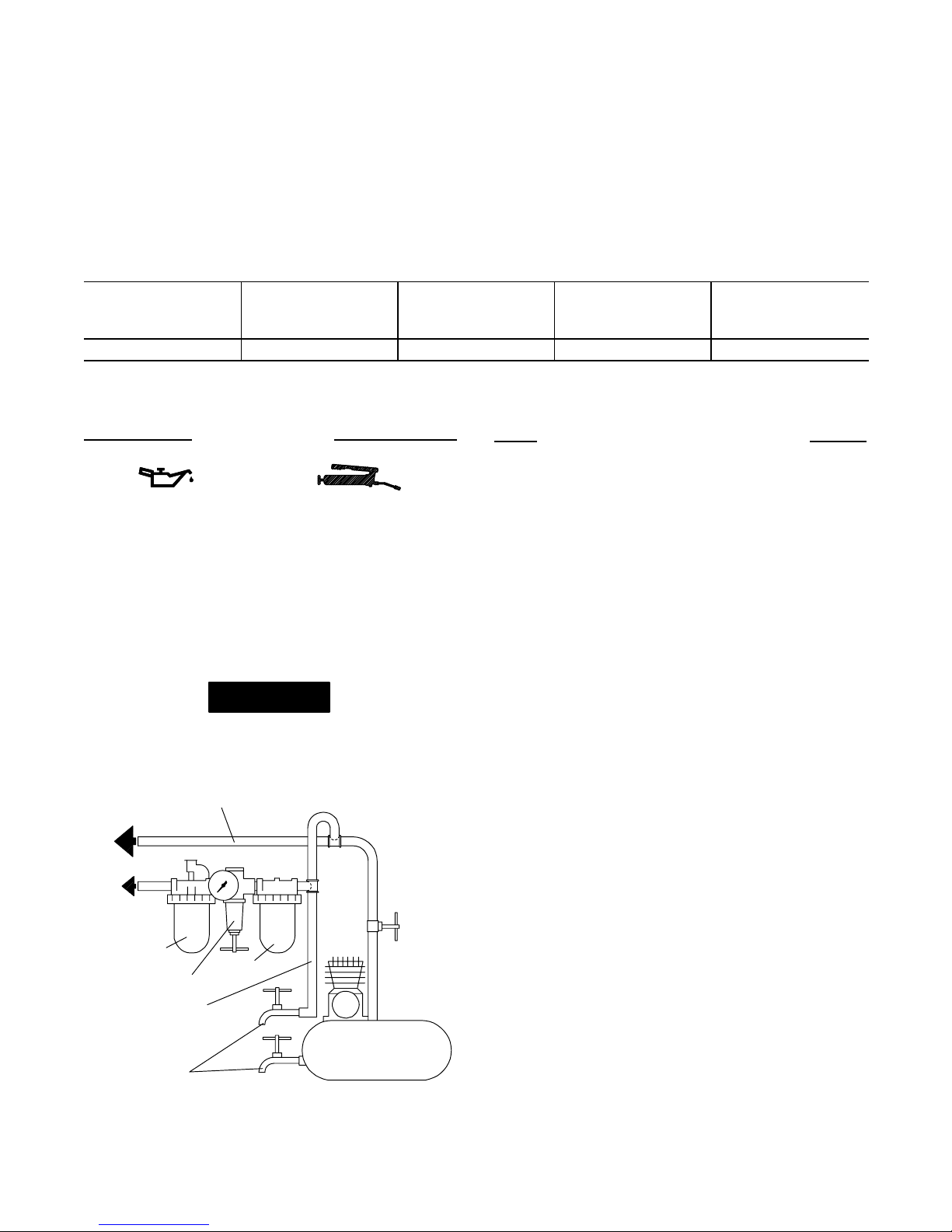
LINHAS PRINCIPAIS 3 VEZES O TAMANHO DA
PARA
SISTEMA DE AR
PARA
FERRAMENTA
PNEUMÁTICA
LUBRIFICADOR
REGULADOR
LINHA RAMIFICADA
2 VEZES O TAMANHO DA
ENTRADA DA FERRAMENTA PNEUMÁTICA
ENTRADA DA FERRAMENTA PNEUMÁTICA
FILTRO
COMPRESSOR
DRENE
REGULARMENTE
(Desenho TPD905–1)
MONTAGEM DO ACESSÓRIO
DE CORTE
Para montar um acessório de corte TD–RK4 ou TD–RK6
numa Esmeriladora TD200 ou TD250 que tenha uma pinça,
proceda da seguinte forma :
1. Use uma Chave Manual de Bocas para segurar a Máquina
evitando assim que esta gire. Desaparafuse a porca da
pinça da esmeriladora. Retire a Pinça.
2. Segure a ferramenta num torno de bancada, protegendo–a
com mordentes de cobre ou couro, com o eixo para cima.
Com uma chave de 1–1/2”, desaparafuse e remova a
Porca da Pinça. Esta é uma rosca à esquerda. Gire a
porca no sentido dos ponteiros do relógio para
removê–la.
3. Instale o Acessório de Corte.
4. Aperte a Porca da Pinça no Veio da Máquina com um
torque entre 27 e 34 Nm (20 e 25 pés–lb). Esta é uma
rosca à direita. Gire a Porca no sentido contrário ao
dos ponteiros do relógio para a apertar.
5. Coloque a Pinça no veio da máquina e aperte livremente
a Porca. Introduza um acessóro de corte na pinça e aperte
a respectiva porca.
6. Instale o Acessório Adapatador Final sobre a mó e aperte
o Acessório entre 2,7 e 3,4 Nm (2,0 e 2,5 pés–lb). Esta é
uma rosca à esquerda. Gire a Porca no sentido
contrário ao dos ponteiros do relógio para a apertar.
7. Instale a Porca e aperte–a com um torque de 1,3 a 2,0 Nm
(12 e 18 pés–lb).
8. Aperte a Porca e o Acessório Adaptador Final.
9. Esse aperto deve obedecer ao seguinte torque :
19,0 e 25,8 Nm (14 e 19 pés–lbs).
10. Se se usar uma Guia Final de Aperto, esta deverá ser
colocada posteriormente ao acessório adaptador com um
aperto entre 4,1 e 5,4 Nm (3 e 4 pés–lb).
18
Page 19
COLOCANDO A FERRAMENTA EM FUNCIONAMENTO
REV.000
GUIA FINAL DE APERTO
RESSALTO
Dimensões da Guia Final de Aperto
(Desenho TPD1208)
NÚMERO DE REFERÊNCIA PARA PEDIDO A B C D E
R120–128–2 (para haste de 1/4”) 1–1/2 3/8 3/8 1/8 1/2–20NF
R120–128–7 (para haste de 1/4”)2–1/2 1/2 1/2 3/16 1/2–20NF
LG2–129–1 (para haste de 3/8”) 2–1/2 1/2 5/8 1/8 5/8–18UNF
K Nota : Ressalto = 1/2 (Dimensão “B” menos o diâmetro do acessório da guia final de aperto).
O seguinte equipamento está disponível por um custo extra e deve ser encomendado separadamente :
1. Arranjo do Acoplamento do Acessório
para modelos que utilizem bites de diâmetro de 1/4 ” Referência No. TD–RK4. . . . . . . . . . . . . . . . . . . . .
ara modelos que utilizem bites de diâmetro de 3/8 ” Referência No. TD–RK6. . . . . . . . . . . . . . . . . . . . . .
2. Guia Final de Aperto (para Acoplamento do Acessáorio)
para haste de 1/4” Referência No. R120–128–2. . . . . . . . . . . . . . . . . . . . . . . . . . . . . . . . . . . . . . . . . . . . . . . . . .
para haste de 1/4” Referência No. R120–128–7. . . . . . . . . . . . . . . . . . . . . . . . . . . . . . . . . . . . . . . . . . . . . . . . . .
para haste de 3/8” Referência No. LG2–129–1. . . . . . . . . . . . . . . . . . . . . . . . . . . . . . . . . . . . . . . . . . . . . . . . . .
Todos os modelos listados na página 5 podem ser trocados por ferramentas com escape frontal ao inverter o Anel de Fluxo e
alinhar o indicador marcado com a “F”no Corpo. Para pedir uma ferramenta com escape frontal de fábrica substitua a
letra “F” pela letra “R” nos modelos acima. Exemplo : O Modelo com Escape Traseiro TD12RG4 torna–se Modelo com
Escape Frontal TD120FG4.
AVISO
19
Page 20
COLOCANDO A FERRAMENTA EM FUNCIONAMENTO
REV.000
NOVO GUIA DE COMBINAÇÃO DE CORES ENTRE A ESMERILADORA E O ACESSÓRIO
A Ingersoll–Rand é pioneira no desenho de um novo sistema
de código de cores para :
1. Simplificar a identificação da velocidade aferida de uma
ferramenta através de uma única combinação de cores
correspondentes.
(LEIA DA ESQUERDA PARA A DIREITA)
COR DA
VELOCIDADE NA
PLACA DE
IDENTIFICAÇÃO
VELOCIDADE
AFERIDA DA
FERRAMENTA
VERMELHA 35,000
LARANJA 30,000
AMARELA 25,000
VERDE 20,000
AZUL 18,000
CINZA 15,000
MARRON
CLARO 12,000
VIOLETA 9,000
ACESSÓRIO DE INTERVALO SEGU R O (MÁXIMA VELOCIDADE DE OPERAÇÃO)
,
VERMELHA
LARANJA
AMARELA
ESPECIFICAÇÕES
2. Comunicam facilmente os painéis traseiros e acessórios
apropriados para cada ferramenta através de um sistema
de códigos de combinação de cores nos paineis traseiros
e/ou acessórios correspondentes à Esmeriladora.
3. A tabela abaixo demonstra o sistema de códigos de cores
correspondentes à Esmeriladora e ao Acessório.
,
,
VERDE
,
AZUL
,,
CINZA
MARRON
CLARO
(Desenho TPD1146–1)
,,
VIOLETA
1/4” PINÇA
Modelo Velocidade Livre
TD250RG4
TD200RG4
TD180RG4
TD120RG4
25.000
20.000
18.000
12.000
1/4” PINÇA
TX250RG4
TX180RG4
TD120RG4
25.000
18.000
12.000
3” ROSCA DO FUSO
TX180RH63 18.000
3” ROSCA DO FUSO
TXD180RH63 18.000
20
Page 21
MAINTENANCE SECTION
21
(Dwg. TPA1291–3)
REV.000
Page 22
MAINTENANCE SECTION
22
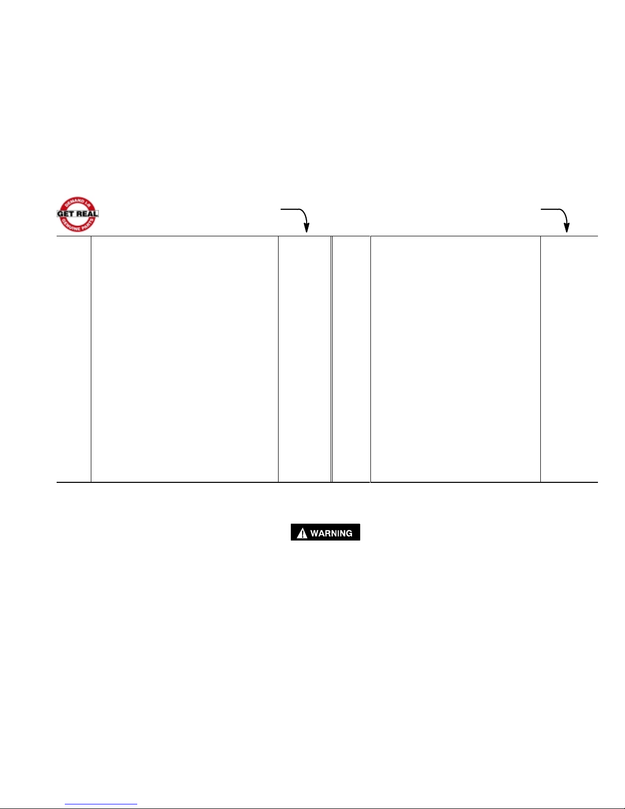
PART NUMBER FOR ORDERING PART NUMBER FOR ORDERING
Common parts for ALL TD, TX and TXD Grinders
15 Front End Plate Spacer . . . . . . . . . . . . . . . . . . . . . LG2–65
1 Inlet Assembly . . . . . . . . . . . . . . . . . . . . . . . . . . . . . . . . . LG2–A465 • 16 Front Seal Cup Assembly . . . . . . . . . . . . . . . . . . . 61H–A32
2 Inlet Screen . . . . . . . . . . . . . . . . . . . . . . . . . . . . . . . R1602–61 17 Front Rotor Bearing . . . . . . . . . . . . . . . . . . . . . . . . LG2–24
• 3 Inlet Seal . . . . . . . . . . . . . . . . . . . . . . . . . . . . . . . . . R18LF–21 18 Flow Ring
4 Throttle Valve Spring Seat . . . . . . . . . . . . . . . . . . . . . . . . LG3–592 for TD120 and TX120 (12 000 rpm)
4A Throttle Valve Spring . . . . . . . . . . . . . . . . . . . . . . . . . . . . 7L–51 (grey) . . . . . . . . . . . . . . . . . . . . . . . . . . . . . . LG2–103–0
4B Throttle Valve . . . . . . . . . . . . . . . . . . . . . . . . . . . . . . . . . LG2–302 for TD180, TX180 and TXD180
4C Throttle Valve Seat . . . . . . . . . . . . . . . . . . . . . . . . . . . . . LG2–303 (18 000 rpm) (brown) . . . . . . . . . . . . . . . . . LG2–103–1
4D Throttle Valve Case . . . . . . . . . . . . . . . . . . . . . . . . . . . . . LG2–300A for TD200 and TX200 (20 000 rpm)
5 Motor Housing . . . . . . . . . . . . . . . . . . . . . . . . . . . . . . . . . LG2–40 (khaki) . . . . . . . . . . . . . . LG2–103–2
6 Throttle Lever . . . . . . . . . . . . . . . . . . . . . . . . . . . . . . . . . LG2–273 for TD250 and TX250(25 000 rpm)
6A Locking Throttle Lever Assembly (red) . . . . . . . . . . . . . . . . . . . . . . . . . . . . . . . LG2–103–3
(for all models ending in L or C) . . . . . . . . . . . . . . . . . . . LG2–A400 19 High Profile Flange . . . . . . . . . . . . . . . . . . . . . . . . LG2–23
* Lever Lock . . . . . . . . . . . . . . . . . . . . . . . . . . . . . . . . LG1–402 # 19A Low Profile Concentric Flange (for all models
* Lock Spring . . . . . . . . . . . . . . . . . . . . . . . . . . . . . . . LG1–405 ending in C) . . . . . . . . . . . . . . . . . . . . . . . . . . . . . . LG3R–23
* Lock Pin . . . . . . . . . . . . . . . . . . . . . . . . . . . . . . . . . . 5UT–757 20 Flange Clamp . . . . . . . . . . . . . . . . . . . . . . . . . . . . . LG2–29
7 Throttle Lever Pin . . . . . . . . . . . . . . . . . . . . . . . . . . . . . . 61H–120 + 20A Exhaust Hose Adapter . . . . . . . . . . . . . . . . . . . . . . LG2–184
8 Throttle Valve Plunger . . . . . . . . . . . . . . . . . . . . . . . . . . . LG2–191 + 20B Exhaust Hose . . . . . . . . . . . . . . . . . . . . . . . . . . . . . 3RL–284
9 Rear Rotor Bearing . . . . . . . . . . . . . . . . . . . . . . . . . . . . . R120–127 + 20C Hose Retainer . . . . . . . . . . . . . . . . . . . . . . . . . . . . . 6WT–203
• 10 Rear Rotor Bearing Spacer (2) . . . . . . . . . . . . . . . . . . . . 400–25–191 * Warning Label
• 11 Rear Rotor Bearing Retainer . . . . . . . . . . . . . . . . . . . . . . LG1–118 for models ending in H63–EU . . . . . . . . . . . EU–63–99
12 Rotor . . . . . . . . . . . . . . . . . . . . . . . . . . . . . . . . . . . . . . . . LG2–53–4 for all other models ending in –EU . . . . . . . EU–99
• 13 Vane Packet (set of 4 Vanes) . . . . . . . . . . . . . . . . . . . . . . DG21–42–4 for all other models . . . . . . . . . . . . . . . . . . . LG2–99
14 Front End Plate . . . . . . . . . . . . . . . . . . . . . . . . . . . . . . . . LG2–11
* Not illustrated.
• To keep downtime to a minimum, it is desirable to have on hand certain repair parts. We recommend that you stock one (pair or set) of each part indicated by a
bullet (•) for every four tools in service.
+ Standard equipment with models ending in M, MC or ML and ALL Front Exhaust models; optional equipment on all other models.
# Always install a Locking Throttle Lever Assembly (6A) on a tool with a Low Profile Concentric Flange (19A). Do not equip a tool with a standard
non–locking Lever (6) and Low Profile Concentric Flange. This can allow the tool to continue to run if dropped or set down.
REV.000
Page 23
MAINTENANCE SECTION
23
PART NUMBER FOR ORDERING PART NUMBER FOR ORDERING
* Nameplate 34 Arbor . . . . . . . . . . . . . . . . . . . . . . . . . . . . . . . . LE2–4–5
for TD120 models ending in –EU . . . . LG212–EU–301 35 Arbor Housing . . . . . . . . . . . . . . . . . . . . . . . . . LE2–20–5
for all other TD120 models . . . . . . . . . LG212–301 36 Arbor Housing Plug . . . . . . . . . . . . . . . . . . . . . EG220–92
for TD180 models ending in –EU . . . . LG218–EU–301 37 Front Arbor Bearing . . . . . . . . . . . . . . . . . . . . WFS182–22
for all other TD180 models . . . . . . . . . LG218–301 37A Arbor Bearing Shield (for models
for TD200 models ending in –EU . . . . LG220–EU–301 ending in G4) . . . . . . . . . . . . . . . . . . . . . . . . . . LE2–200
for all other TD200 models . . . . . . . . . LG220–301 38 Arbor Bearing Retaining Ring . . . . . . . . . . . . . W22–118
for TD250 models ending in –EU . . . . LG225–EU–301
Parts common to all
for all other TD250 models . . . . . . . . . LG225–301
models ending in G4
for TX120 models . . . . . . . . . . . . . . . . . LE212–301 39 Collet Body . . . . . . . . . . . . . . . . . . . . . . . . . . . LG2–290
for TX180 models ending in –EU . . . . LE218–EU–301 39A Front Seal Cup . . . . . . . . . . . . . . . . . . . . . . . . . 61H–32
for all other TX180 models . . . . . . . . . LE218–301 40 Collet
for TXD180 models ending in –EU . . . LED218–EU–301 for models ending in RT4 or –EU . . . . G160HD–700–6mm
for all other TXD180 models . . . . . . . . LED218–301 for all other models . . . . . . . . . . . . . . . . G160HD–700–1/4
for TX200 models . . . . . . . . . . . . . . . . . LE220–301 41 Collet Nut Assembly . . . . . . . . . . . . . . . . . . . . DG120–699A
for TX250 models ending in –EU . . . . LE225–EU–301 41A Collet Body Wrench . . . . . . . . . . . . . . . . . . . . DG10–69
for all other TX250 models . . . . . . . . . LE225–301 41B Collet Nut Wrench . . . . . . . . . . . . . . . . . . . . . . DG120–69
Additional parts for all TD models Parts common to all
21 Clamp Spacer . . . . . . . . . . . . . . . . . . . . . . . . . . LG2–46
models ending in H63
22 Clamp Nut . . . . . . . . . . . . . . . . . . . . . . . . . . . . LG2–27 42 Guard Adapter Assembly . . . . . . . . . . . . . . . . LE2–A710
Additional parts for all
43 Guard Adapter Screw . . . . . . . . . . . . . . . . . 231–638
extended TXD models
44 3” Wheel Guard . . . . . . . . . . . . . . . . . . . . . . . . LE2–931
23 Clamp Sleeve . . . . . . . . . . . . . . . . . . . . . . . . . . LE2–176 45 Wheel Guard Mounting Screw (3) . . . . . . . . . LE2–667
24 Arbor . . . . . . . . . . . . . . . . . . . . . . . . . . . . . . . . LE2–4 46 Mounting Screw Washer (3) . . . . . . . . . . . . . . L01–67
25 Arbor Housing . . . . . . . . . . . . . . . . . . . . . . . . . LE2–20 47 3” Straight Wheel Adapter . . . . . . . . . . . . . . . LE2–4–H63
26 Arbor Housing Plug . . . . . . . . . . . . . . . . . . . . . EG220–92 47A Front Seal Cup . . . . . . . . . . . . . . . . . . . . . . . . . 61H–32
27 Front Arbor Bearing . . . . . . . . . . . . . . . . . . . . WFS182–22 48 3” Wheel Flange . . . . . . . . . . . . . . . . . . . . . . . DEG31–16
28 Arbor Bearing Retaining Ring . . . . . . . . . . . . . W22–118 49 Flange Nut . . . . . . . . . . . . . . . . . . . . . . . . . . . . 23–697
Additional parts for all TX models Accessories
29 Arbor Coupling . . . . . . . . . . . . . . . . . . . . . . . . LE2–304 * Bearing Inserting Tool (for TX and TXD
30 Clamp Sleeve . . . . . . . . . . . . . . . . . . . . . . . . . . LE2–276 models) (2 pieces) . . . . . . . . . . . . . . . . . . . . . . LE2–950
31 Arbor Bearing Nut (2) . . . . . . . . . . . . . . . . . . . LE2–85 * Cone Wheel Adapter (for TX models) . . . . . . LE2–104–L6
32 Coupling Retaining Ring (2) . . . . . . . . . . . . . . RX3–729 * Exhaust Deflector Assembly . . . . . . . . . . . . . . 04353207
33 Rear Arbor Bearing . . . . . . . . . . . . . . . . . . . . . LE2–22
* Not illustrated.
REV.000
Page 24
MAINTENANCE SECTION
REV.000
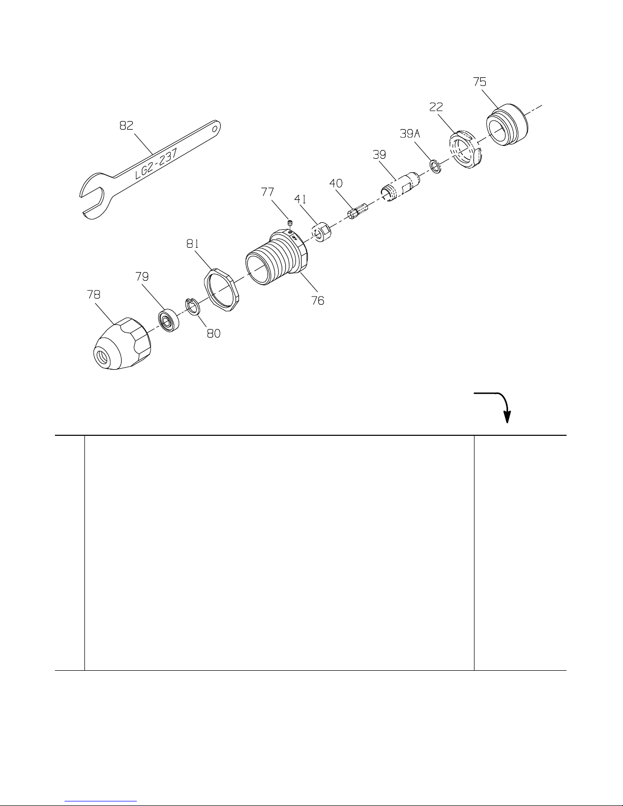
ROUTER ATTACHMENT FOR MODELS TD200 AND TD250 WITH COLLETS
(Dwg. TPC542)
PART NUMBER FOR ORDERING
Router Attachment Assembly
for models using 1/4” diameter bits . . . . . . . . . . . . . . . . . . . . . . . . . . . . . . . TD–RK4
for models using 3/8” diameter bits . . . . . . . . . . . . . . . . . . . . . . . . . . . . . . . TD–RK6
75 Clamp Spacer . . . . . . . . . . . . . . . . . . . . . . . . . . . . . . . . . . . . . . . . . . . . . . . . . . . . . . . . . . LG2–19
76 Nosepiece Adapter . . . . . . . . . . . . . . . . . . . . . . . . . . . . . . . . . . . . . . . . . . . . . . . . . . . . . . LG2–124
77 Adapter Lock Screw . . . . . . . . . . . . . . . . . . . . . . . . . . . . . . . . . . . . . . . . . . . . . . . . . . . . 0E9–561
78 Nosepiece Assembly
for models using 1/4” collet . . . . . . . . . . . . . . . . . . . . . . . . . . . . . . . . . . . . . LG2–A125–1
for models using 3/8” collet . . . . . . . . . . . . . . . . . . . . . . . . . . . . . . . . . . . . . LG2–A125–3
79 Nosepiece Bearing
for LG2–A125–1 . . . . . . . . . . . . . . . . . . . . . . . . . . . . . . . . . . . . . . . . . . . . . . TD200–127
for LG2–A125–3 . . . . . . . . . . . . . . . . . . . . . . . . . . . . . . . . . . . . . . . . . . . . . . G160–22
80 Bearing Retaining Ring
for LG2–A125–1 . . . . . . . . . . . . . . . . . . . . . . . . . . . . . . . . . . . . . . . . . . . . . . RXA21–343
for LG2–A125–3 . . . . . . . . . . . . . . . . . . . . . . . . . . . . . . . . . . . . . . . . . . . . . . 3RL–28
81 Lock Nut . . . . . . . . . . . . . . . . . . . . . . . . . . . . . . . . . . . . . . . . . . . . . . . . . . . . . . . . . . . . . R120–126
82 Lock Nut Wrench . . . . . . . . . . . . . . . . . . . . . . . . . . . . . . . . . . . . . . . . . . . . . . . . . . . . . . . LG2–237
24
Page 25

MAINTENANCE SECTION
REV.000
Always wear eye protection when operating or
performing maintenance on this tool.
Always turn off the air supply and disconnect the air
supply hose before installing, removing or adjusting
any accessory on this tool, or before performing any
maintenance on this tool.
LUBRICATION
Whenever one of these Grinders is disassembled for
overhaul or replacement of parts, lubricate as follows:
1. Always wipe the Vanes (13) with a light film of oil
before inserting them into the vane slots.
2. Lubricate the Front Seal Cup Assembly (16, 39A or
47A) with Ingersoll–Rand No. 50 Oil.
3. Inject 0.5 to 1.0 cc of Ingersoll–Rand No. 10 Oil into
the Air Inlet Assembly (1) after assembly.
DISASSEMBLY
General Instructions
1. Do not disassemble the tool any further than
necessary to replace or repair damaged parts.
2. When grasping a tool or part in a vise, always use
leather–covered or copper–covered vise jaws to
protect the surface of the part or tool and help prevent
distortion. This is particularly true of threaded
members and housings.
3. Do not remove any part which is a press fit in or on a
subassembly unless the removal of that part is
necessary for repairs or replacement.
4. Do not disassemble the tool unless you have a
complete set of new gaskets and O–rings for
replacement.
5. Do not press any needle bearing from a part unless
you have a new needle bearing on hand for
installation. Needle bearings are always damaged
during the removal process.
Steps common to ALL models ending in G4
1. Using the Collet Body Wrench (41A) to hold the
Collet Body (39) from turning and the Collet Nut
Wrench (41B) on the Collet Nut Assembly (41),
unscrew and remove the Nut.
2. Remove the Collet (40).
Steps common to ALL models ending in H63
1. Use an adjustable spanner wrench in one of the holes
in the Wheel Adapter (47) and a 9/16” wrench to
loosen and remove the Flange Nut (49). Remove the
Wheel Flange (48) and grinding wheel.
2. Using a 5/32” hex wrench, loosen the Guard
Adapter Screw (43) and pull the Guard Adapter
Assembly (42) and assembled Guard (44) from the
Arbor Housing (35).
Steps common to ALL TD models
1. Grasp the tool in copper–covered or leather–covered
vise jaws with the spindle upward and using a 1–1/2”
wrench, unscrew and remove the Clamp Nut (22).
This is a left–hand thread and must be rotated
clockwise.
2. Remove the Clamp Spacer (21) and Flange
Clamp (20).
3. Pull the Flange (19) and Flow Ring (18) off the front
of the Motor Housing (5).
4. Grasp the Collet Body and pull the assembled motor
out of the Motor Housing. Remove the Motor
Housing from the vise and remove the two Rear Rotor
Bearing Spacers (10) from the bottom of the Housing.
5. Remove the Vanes (13) from the Rotor (12).
6. Grasp the Rotor in copper–covered or leather–covered
vise jaws with the Collet Body (39) upward. Using the
Collet Body Wrench (41A), unscrew and remove the
Collet Body. Remove the Front Seal Cup Assembly
(39A) from the Collet Body.
Steps common to ALL TXD models
1. Use a screwdriver to remove the Arbor Housing Plug
(26) and rotate the Arbor (24) until the crosshole in
the Arbor is aligned with the opening in the Arbor
Housing (25).
2. Insert a 5/32” (4 mm) diameter hardened steel rod
approximately 6” (150 mm) long through the arbor
crosshole to sprag the Arbor. Using a spanner wrench
on the Wheel Adapter (47), unscrew and remove the
Adapter.
3. Grasp the tool in copper–covered or leather–covered
vise jaws with the spindle upward and using a 1–1/2”
wrench, unscrew and remove the Arbor Housing. This
is a left–hand thread and must be rotated clockwise.
4. Remove the Clamp Sleeve (23), Flange Clamp (20),
Flange (19) and Flow Ring (18) from the front of the
Motor Housing (5).
5. Using snap ring pliers, remove the Arbor Bearing
Retaining Ring (28).
6. Stand the Arbor Housing (25), threaded end upward,
on the table of an arbor press and using a rod or piece
of tubing that contacts the outer ring of the bearing,
press the Front Arbor Bearing (27) from the Arbor
Housing.
7. Grasp the Arbor and pull the assembled motor out of
the Motor Housing. Remove the Motor Housing from
the vise and remove the two Rear Rotor Bearing
Spacers (10) from the bottom of the Housing.
25
Page 26

MAINTENANCE SECTION
REV.000
8. Remove the Vanes (13) from the Rotor (12).
9. Grasp the Rotor in copper–covered vise jaws with the
Arbor upward. Using a 5/32” diameter rod through
the crosshole, unscrew and remove the Arbor.
Steps common to ALL TX models
1. Use a screwdriver to remove the Arbor Housing Plug
(36) and rotate the Arbor (34) until the crosshole in
the Arbor is aligned with the opening in the Arbor
Housing (35).
2. Insert a 5/32” (4 mm) diameter hardened steel rod
approximately 6” (150 mm) long through the arbor
crosshole to sprag the Arbor.
For models ending in H63
Using a spanner wrench on the Wheel Adapter (47),
unscrew and remove the Adapter. Remove the Front
Seal Cup Assembly (47A) from the Adapter.
For models ending in G4
Using the Collet Body Wrench (41A) on the Collet
Body (39), unscrew and remove the Collet Body.
Remove the Front Seal Cup Assembly (39A) from the
Collet Body.
3. Grasp the tool in copper–covered or leather–covered
vise jaws with the spindle upward and using a 1–1/2”
wrench, unscrew and remove the Arbor Housing (35).
This is a left–hand thread and must be rotated
clockwise.
4. Remove the Clamp Sleeve (30), Arbor Coupling (29)
and the Flange Clamp (20).
5. Grasping the Arbor Bearing Nut (31), pull the Arbor
out of the Arbor Housing.
6. Using snap ring pliers, remove the Arbor Bearing
Retaining Ring (38) from the Arbor Housing.
7. For models ending in G4, remove the Arbor Bearing
Shield (37A).
8. Stand the Arbor Housing (35), threaded end upward,
on the table of an arbor press and using a rod or piece
of tubing that contacts the outer ring of the bearing,
press the Front Arbor Bearing (37) from the Arbor
Housing.
9. Insert a 5/32” (4 mm) diameter hardened steel rod
approximately 6” (150 mm) long through the
crosshole in the Arbor and using a 1/2” wrench on the
Arbor Bearing Nut, unscrew and remove the Nut.
10. Using an arbor press, press the Rear Arbor Bearing
(33) off the Arbor.
11. Pull the Flange (19) and Flow Ring (18) off the front
of the Motor Housing (5).
12. Grasp the Arbor Bearing Nut on the rotor shaft and
pull the assembled motor out of the Motor Housing.
Remove the Motor Housing from the vise and remove
the two Rear Rotor Bearing Spacers (10) from the
bottom of the Housing.
13. Remove the Vanes (13) from the Rotor (12).
14. Grasp the Rotor in copper–covered or leather–covered
vise jaws with the Arbor Bearing Nut upward. Using a
1/2” wrench, unscrew and remove the Arbor Bearing
Nut.
Steps common to ALL models
1. If the Front Rotor Bearing (17) must be replaced,
support the Front End Plate (14) between two blocks
on the table of an arbor press. Place the blocks as
close to the body of the Rotor (12) as possible and
press theRotor from the Bearing and End Plate.
Remove the Front End Plate Spacer (15) and Front
Seal Cup Assembly (16) from the hub of the Rotor.
2. If the Rear Rotor Bearing (9) must be replaced, use
snap ring pliers to remove the Rear Rotor Bearing
Retainer (11).
3. Using a bearing puller, pull the Rear Rotor Bearing
off the hub of the Rotor.
Disassembly of the Inlet and Throttle
1. Using a 6 point 15/16" socket, unscrew and remove
the Inlet Assembly (1).
2. Remove the Inlet Seal (3) and Inlet Screen (2) from
the Inlet.
3. Remove the Throttle Valve Spring Seat (4), Throttle
Valve Spring (4A) and Throttle Valve (4B)from the
Motor Housing (5).
4. If the Throttle Valve Seat (4C) must be replaced,
insert a hooked tool through the central opening of the
Seat and, catching the underside of the Seat, pull it
from the Housing.
5. If the Throttle Valve Cartridge Case (4D) must be
replaced, insert two hooked tools through the central
opening of the Case approximately 180 degrees apart
and, catching the underside of the Case, pull it from
the Housing.
6. Press the Throttle Lever Pin (7) from the Housing and
remove the Throttle Lever (6). Remove the Throttle
Valve Plunger (8).
ASSEMBLY
General Instructions
1. Always press on the inner ring of a ball–type bearing
when installing the bearing on a shaft.
2. Always press on the outer ring of a ball–type bearing
when pressing the bearing into a bearing recess.
3. Whenever grasping a tool or part in a vise, always use
leather–covered or copper–covered vise jaws. Take
extra care not to damage threads or distort housings.
4. Except for bearings, always clean every part and wipe
every part with a thin film of oil before installation.
5. Check every bearing for roughness. If an open bearing
must be cleaned, wash it thoroughly in clean solvent
and dry with a clean cloth. Sealed or shielded
bearings should not be cleaned. Work grease into
every open bearing before installation.
6. Apply a film of O–ring lubricant to every O–ring
before installation.
26
Page 27

MAINTENANCE SECTION
REV.000
Assembly of the Inlet and Throttle
1. Insert the Throttle Valve Plunger (8) into the Motor
Housing (5).
2. Position the Throttle Lever (6) on the Motor Housing
and using an arbor press, press the Throttle Lever Pin
(7) into the Housing and Lever. The Lever will retain
the Plunger in the Housing.
3. If the Throttle Valve Cartridge Case (4D) was
removed, lubricate the outside and the throttle stem
end of the Case with O–ring lubricant. Using a
wooden dowel, push the Case, open end trailing, into
the Motor Housing.
4. If the Throttle Valve Seat (4C) was removed, use a
5/8” wooden dowel with a flat end to push the Seat
into the Motor Housing.
5. Push the small end of the Throttle Valve Spring (4A)
onto the end of the Throttle Valve (4B) with the short
stem until the Spring snaps into position around the
hub and remains there. Install the dish end of the
Throttle Valve Spring Seat (4) onto the large end of
the Throttle Valve Spring.
6. Holding the Housing with the Lever downward, make
sure the Plunger is out of the way and insert the
assembled Throttle Valve, long stem end leading, into
the housing recess.
7. Push the Inlet Screen (2), closed end leading, into the
Inlet Assembly (1). After moistening a new Inlet Seal
(3) with o–ring lubricant and being careful not to nick
the Seal on the threads of the Inlet, install the Seal on
the Inlet.
8. Thread the Inlet Assembly into the Housing and
tighten it between 13 to 15 ft–lb (18 to 20 Nm)
torque.
Assembly of the Motor
Steps common to ALL models
1. If the Rear Rotor Bearing (9) was removed, stand the
Rotor (12) upright on the table of an arbor press with
the threaded end downward. Make sure the threaded
end passes through a hole drilled in a block so that the
Rotor rests against the large rotor body. Press the Rear
Rotor Bearing onto the hub of the Rotor.
2. Install the Rear Rotor Bearing Retainer (11) in the
groove on the hub of the Rotor.
3. Install the Front End Plate (14), counterbored end
trailing, onto the threaded hub of the Rotor. Using
finger pressure, press the Front Seal Cup Assembly
(16), felt end trailing, onto the end of the Front End
Plate Spacer (15) that is opposite the large internal
bevel. Continue pressing until the felt end is flush
with the end of the Spacer. Lubricate the felt with
Ingersoll–Rand No. 50 Oil. Place the assembled
Spacer, Seal Assembly trailing, onto the threaded hub
of the Rotor. Make sure the Seal Assembly enters the
recess in the Front End Plate.
Before performing the next step, be aware that the
Front Rotor Bearing is a flush ground bearing and
must be installed in a specific manner. The end of
the Bearing with a black stain or hash marks must
be away from the Spacer.
4. Stand the Rotor on the table of an arbor press with the
threaded end upward and press the Front Rotor
Bearing (17) onto the hub of the Rotor.
5. Grasp the assembled Rotor in copper–covered or
leather–covered vise jaws with the threaded rotor hub
upward.
6. For TD models, using finger pressure, press the Front
Seal Cup Assembly (39A or 47A), felt end trailing,
onto the rotor end of the Collet Body (39)or Wheel
Adapter (47). Continue pressing until the felt end is
flush with the end of the Collet Body or Wheel
Adapter. Lubricate the felt with Ingersoll–Rand No.
50 Oil.
7. If the Front Arbor Bearing (27) must be replaced on a
Model TXD, proceed as follows before assembling
the motor:
a. Place the Clamp Sleeve (23) on the table of an
arbor press and install the large end of the Arbor
Housing (25) on the Clamp Sleeve.
b. Slide the Front Arbor Bearing onto the threaded
hub of the Arbor (24) and insert the Arbor, bearing
end trailing, into the Housing. Make certain the
end of the Arbor rests on the arbor press table and
the Bearing is aligned with the bore in the
Housing.
c. Install the small piece of the LE2–950 Bearing
Inserting Tool over the Arbor and press the
Bearing into the Housing until it stops against the
shoulder of the Arbor.
d. Remove the Arbor from the Housing and
Bearing but keep the parts together so that the
same parts are installed together. Do not mix and
match Arbors with Bearings and Housings.
8. Thread the Collet Body and Seal Assembly (for TD
models), Arbor (24) (for TXD models) or the Arbor
Bearing Nut (31), Retainer end leading, (for TX
models) onto the Rotor and using a torque wrench,
tighten the Collet Body, Arbor or Arbor Bearing Nut
between 14 and 19 ft–lb (19 and 26 Nm) torque.
9. Inject approximately 3/4 cc of Ingersoll–Rand No. 68
Grease into the small recess at the bottom of the
motor housing bore. Drop the two Rear Rotor
Bearing Spacers (10) into the bottom of the motor
housing bore.
10. Wipe each Vane (13) with a light film of oil and insert
a Vane into each vane slot in the Rotor.
27
Page 28

MAINTENANCE SECTION
REV.000
11. Grasp the Collet Body, Arbor or Arbor Bearing
Nut and insert the assembled Rotor into the Motor
Housing (5).
12. Assemble the Flow Ring (18) with the Flange (19)
before installing the Flange on the Housing. Mate the
Flow Ring to the end of the Flange without
perforations. The positioning of the Flow Ring is
dictated by the desired exhaust. To set the tool
exhaust, proceed as follows:
a. For front exhaust tools, align the notched
projection on the edge of the Flow Ring with the
letter “F” on the Housing.
b. For rear exhaust tools, align the notched
projection on the edge of the Flow Ring with the
letter “R” on the Housing.
13. Install the assembled Flange, Flow Ring leading, onto
the front of the Motor Housing.
14. Grasp the Motor Housing in copper–covered or
leather–covered vise jaws with the Collet Body, Arbor
or Arbor Bearing Nut upward. Do not distort the
Housing.
15. Position the Flange Clamp (20) against the Flange.
Steps common to ALL TX models
1. Lubricate the Arbor Coupling (29) with
approximately 1 cc of Ingersoll–Rand No. 68 Grease
and position the Coupling over the Arbor Bearing Nut
(31). Position the Clamp Sleeve (30) over the Arbor
Coupling against the Front Rotor Bearing (17).
2. If the Rear Arbor Bearing (33) was removed, proceed
as follows:
a. Stand the larger piece of the LE2–950 Bearing
Inserting Tool on the table of an arbor press.
b. Place the Rear Arbor Bearing on the surface of the
Inserting Tool and align the central opening of the
Bearing with the central opening of the Inserting
Tool.
c. The large body of the Arbor (34) has an annular
groove between the crosshole and one threaded
end. Press that end of the Arbor into the Bearing
until the shoulder of the Arbor stops against the
Bearing.
3. If the Front Arbor Bearing (37) was removed from the
Arbor Housing (35), proceed as follows:
a. If the Rear Arbor Bearing was not removed from
the Arbor, insert a 5/32” (4 mm) hardened steel
rod approximately 6” (150 mm) long through the
crosshole and using a 1/2” wrench, unscrew and
remove the Arbor Bearing Nut (31) from the
Arbor. Do not remove the Bearing.
b. Stand the larger piece of the No. LE2–950 Bearing
Inserting Tool on the table of an arbor press and
insert the Arbor, Rear Arbor Bearing end leading,
into the central opening of the piece until the
Bearing stops against the top of the Inserting Tool.
c. Install the Arbor Housing, threaded end first, over
the Arbor until it stops against the Bearing and
pilots on the Bearing Inserting Tool.
d. Position the Front Arbor Bearing on the Arbor and
using the smaller piece of the No. LE2–950
Bearing Inserting Tool as a pressing tool and pilot,
press the Bearing onto the Arbor until it stops
against the arbor shoulder.
e. For models ending in G4, install the Arbor
Bearing Shield (37A) in the Housing against the
Bearing.
f. Using snap ring pliers, install the Arbor Bearing
Retaining Ring (38) in the Arbor Housing.
4. Insert a 5/32” (4 mm) hardened steel rod
approximately 6” (150 mm) long through the
crosshole and using a 1/2” wrench, thread the Arbor
Bearing Nut onto the Arbor against the Rear Arbor
Bearing. Tighten the Nut between 14 and 19 ft–lb (19
and 26 Nm) torque.
5. Align the rear Arbor Bearing Nut with the hex in the
Arbor Coupling. Thread the Arbor Housing onto the
Motor Housing and tighten the joint between 20 and
25 ft–lb (27 and 34 Nm) torque. This is a left–hand
thread. Turn counterclockwise to tighten.
6. For collet models, insert a 5/32” (4 mm) hardened
steel rod approximately 6” (150 mm) long through the
arbor crosshole. Thread the assembled Collet Body
onto the Arbor and using a torque wrench, tighten the
joint between 14 and 19 ft–lb (19 and 26 Nm) torque.
Steps common to ALL TXD models
1. Position the Clamp Sleeve (23) over the Arbor against
the Front Rotor Bearing (17).
2. Thread the Arbor Housing (25) onto the Motor
Housing and tighten the joint between 20 and 25 ft–lb
(27 and 34 Nm) torque. This is a left–hand thread.
Turn counterclockwise to tighten.
3. Using snap ring pliers, install the Arbor Bearing
Retaining Ring (28) in the Arbor Housing.
Steps common to ALL TD models
1. Position the Clamp Spacer (21) over the Arbor against
the Front Rotor Bearing (17).
2. Thread the Clamp Nut (22) onto the Housing and
tighten the Nut between 20 and 25 ft–lb (27 and
34 Nm) torque. This is a left–hand thread. Turn
counterclockwise to tighten.
28
Page 29

MAINTENANCE SECTION
REV.000
Steps common to ALL models ending in H63
1. Insert a 5/32” (4 mm) diameter hardened steel rod
approximately 6” (150 mm) long through the opening
in the Arbor Housing and Arbor to keep the Arbor
from turning. Using an adjustable spanner wrench,
tighten the Wheel Adapter (47) between 14 and
19 ft–lb (19 and 26 Nm) torque.
2. Remove the rod and install the Arbor Housing Plug
(26 or 36).
3. If the Wheel Guard (44) was removed from the Guard
Adapter (42), attach the Guard to the Adapter with the
three Wheel Guard Mounting Screws (45) and
Mounting Screw Lock Washers (46). Tighten each
Screw between 2–1/2 and 3 ft–lb (3.4 and 4.1 Nm)
torque.
4. Install the assembled Guard Adapter and Wheel
Guard on the front end of the Arbor Housing, flush
with the end of the Housing. Install the Guard
Adapter Screw (43) into the Adapter and tighten the
Screw between 3–1/2 and 4 ft–lb (4.7 and 5.4 Nm)
torque.
5. Install in order the wheel, Wheel Flange (48) and
Flange Nut (49).
6. Use an adjustable spanner wrench inserted into one of
the holes in the Wheel Adapter to hold the Adapter
from turning. Using a 9/16” wrench on the Flange
Nut, tighten the Nut securely.
Steps common to ALL models ending in G4
1. Insert the Collet (40) into the Collet Body (39).
2. Thread the Collet Nut Assembly (41) onto the Collet
Body and use the Collet Body Wrench (41A) and the
Collet Nut Wrench (41B) to tighten the Nut to the
Collet Body.
29
Page 30

MAINTENANCE SECTION
REV.000
TROUBLESHOOTING GUIDE
Trouble Probable Cause Solution
Low power or low free speed Insufficient air pressure Check air line pressure at the Inlet of the Tool. It
must be 90 psig (6.2 bar/620 kPa).
Clogged muffler elements Disassemble the Tool and agitate bare Motor
Housing and Flange in clean, suitable, cleaning
solution. If elements cannot be cleaned, replace
the Motor Housing and/or the Flange.
Plugged Inlet Screen Clean the Inlet Screen in clean, suitable, cleaning
solution or replace the Screen.
Worn or broken Vanes Install a complete set of new Vanes.
Loose Clamp Nut or Arbor
Housing
Worn or broken Motor Housing Replace the Motor Housing.
Internal air leakage in the Motor
Housing indicated by high air
consumption/low speed or air
leaking out the front and rear
exhaust simultaneously.
Grit buildup under the Throttle
Lever restricting full Throttle
Valve Plunger movement.
Bent stem on Throttle Valve Replace the Throttle Valve.
Front Seal Cup Assembly
dragging against the shield of
the Front Rotor Bearing
Excessive runout Bent rotor hub Replace the Rotor.
Loose Collet Nut Tighten the Collet Nut until snug.
Worn or damaged Collet or
Collet Nut
Worn or damaged Front Rotor
Bearing
Bent, worn or broken Extension
Arbor on TX or TXD models
Worn or damaged Front Arbor
Bearing on TX or TXD models
Scoring of End Plate Worn Front End Plate Spacer or
Front End Plate
Worn Front Rotor Bearing Install a new Front Rotor Bearing.
Tighten the Nut or Housing to 20 to 25 ft–lb (27 to
34 Nm) torque.
Replace the Motor Housing.
Remove the Throttle Lever and clean the groove
in the Motor Housing.
Reposition the Front Seal Cup Assembly.
Replace the damaged component and retest.
Replace the Front Rotor Bearing.
Replace the Extension Arbor if, when mounted
between centers, the runout on the arbor body
exceeds 0.002” T.I.R. or 0.0005” T.I.R. on the
bearing mounting diameters.
Replace the Front Arbor Bearing.
Install a new Front End Plate Spacer and Front
End Plate.
30
Page 31

MAINTENANCE SECTION
REV.000
TROUBLESHOOTING GUIDE
Trouble Probable Cause Solution
Leaky Throttle Valve Dirt accumulation on Throttle
Valve or Throttle Valve Seat
Worn Throttle Valve or Throttle
Valve Seat
Excessive dirt build–up beneath
the Throttle Lever
Bent Throttle Valve Plunger Replace the Plunger.
Exhausts at wrong direction Incorrect orientation of the Flow
Ring
Front Rotor Bearing runs hot Incorrect installation of the Front
Seal Cup Assembly
Front End Plate Spacer rubbing
the bore of the Front End Plate
Incorrect Front Rotor Bearing
installation orientation
Slow tool idle Bent or leaky Throttle Valve Replace the Throttle Valve.
Air leakage around Flow Ring Damaged, mutilated or missing
Flange Clamp
Damaged Flow Ring Replace the Flow Ring.
Rough operation/vibration Improper lubrication or dirt
buildup
Worn or broken Rear Rotor
Bearing or Front Rotor Bearing
Worn or broken Rear Arbor
Bearing in TX models or Front
Arbor Bearing in TX or TXD
models
Dirt contaminated Front Arbor
Bearing in TX or TXD models
Bent, worn or broken Extension
Arbor on TX or TXD models
Disassemble, inspect and clean parts.
Replace the Throttle Valve and/or Throttle Valve
Seat.
Clean out the slot area.
Reverse the face of the Flow Ring against the
Motor Housing.
Reposition the Front Seal Cup Assembly flush
with the face of the Front End Plate Spacer.
Replace the Front End Plate and Front End Plate
Spacer combination.
If a black stain or black hashmarks are not visible
on the face of the Bearing when it is assembled
with the End Plate and Rotor, the Bearing is
installed backwards. If possible, remove the Bearing and install it correctly or replace the Bearing.
Replace the Flange Clamp.
Disassemble the Tool and clean in a suitable
cleaning solution. Assemble the Tool and inject
3 cc of the recommended oil into the Inlet and run
the Grinder long enough to coat the internal parts
with the oil.
Replace the worn or broken Bearings. Examine the
Front End Plate, Front End Plate Spacer Front Seal
Cup Assembly and Rear Rotor Bearing Spacers
and replace any damaged parts. If the rear end
plate is damaged, replace the Rotor.
Replace the worn or broken Bearing.
Replace the Bearing.
Replace the Extension Arbor if, when mounted
between centers, the runout on the arbor body exceeds 0.002” T.I.R. or 0.0005” T.I.R. on the bearing mounting diameters.
SAVE THESE INSTRUCTIONS. DO NOT DESTROY.
31
 Loading...