

Ingersoll-Rand TAM7A0C36H31EA, TAM7A0C48H41EA, TAM7A0C42H31EA, TAM7A0B30H21EA, TAM7B0C60H51EA Installer Manual
...Page 1
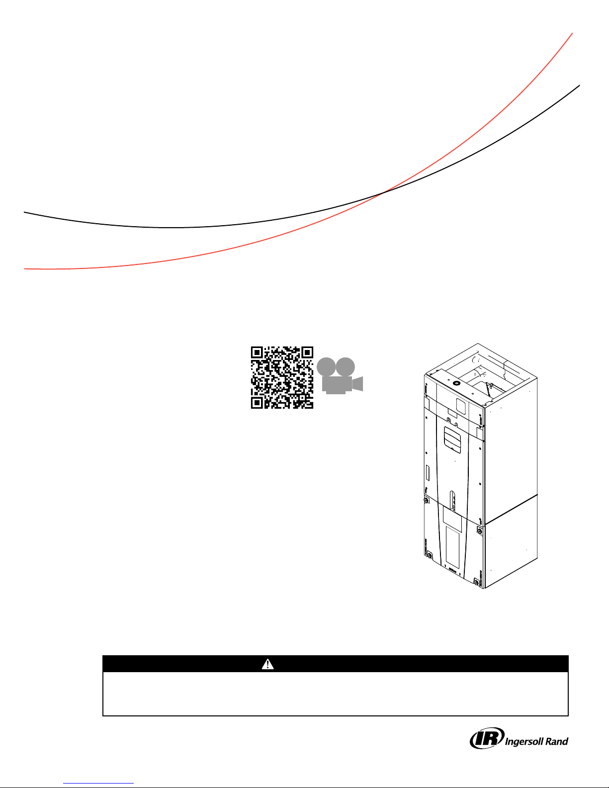
Installer’s Guide
Air Handlers
Convertible 2 — 5 Ton
BBllaacckk EEppooxxyy CCooiillss
TAM7A0A24H21EA
TAM7A0B30H21EA
TAM7A0C36H31EA
TAM7A0C42H31EA
TAM7A0C48H41EA
TAM7B0C60H51EA
SSttaannddaarrdd CCooiillss
TAM7A0A24H21SD
TAM7A0B30H21SD
TAM7A0C36H31SD
TAM7A0C42H31SD
TAM7A0C48H41SD
TAM7B0C60H51SC
Scan or click to view
TAM7 Trouble Shooting
Video Library
Only qualified personnel should install and service the equipment. The installation, starting up, and servicing of heating, ventilating, and
air-conditioning equipment can be hazardous and requires specific knowledge and training. Improperly installed, adjusted or altered
equipment by an unqualified person could result in death or serious injury. When working on the equipment, observe all precautions in the
literature and on the tags, stickers, and labels that are attached to the equipment.
July 2014
NNoottee:: “Graphics in this document are for representation only.
Actual model may differ in appearance.”
NNoottee:: For use with BAYEV or BAYW series heaters ONLY
SSAAFFEETTYY WWAARRNNIINNGG
18-GJ06D2-2E-EN
Page 2
SAFETY SECTION
AIR HANDLERS
IImmppoorrttaanntt — This document contains a wiring
diagram, a parts list, and service information. This is
customer property and is to remain with this unit.
Please return to service information pack upon
completion of work.
WWAARRNNIINNGG
HHAAZZAARRDDOOUUSS VVOOLLTTAAGGEE!!
FFaaiilluurree ttoo ffoollllooww tthhiiss WWaarrnniinngg ccoouulldd rreessuulltt iinn
pprrooppeerrttyy ddaammaaggee,, sseevveerree ppeerrssoonnaall iinnjjuurryy,, oorr ddeeaatthh..
DDiissccoonnnneecctt aallll eelleeccttrriicc ppoowweerr,, iinncclluuddiinngg rreemmoottee
ddiissccoonnnneeccttss bbeeffoorree sseerrvviicciinngg.. FFoollllooww pprrooppeerr
lloocckkoouutt//ttaaggoouutt pprroocceedduurreess ttoo eennssuurree tthhee ppoowweerr
ccaannnnoott bbee iinnaaddvveerrtteennttllyy eenneerrggiizzeedd..
CCAAUUTTIIOONN
GGRROOUUNNDDIINNGG RREEQQUUIIRREEDD!!
FFaaiilluurree ttoo iinnssppeecctt oorr uussee pprrooppeerr sseerrvviiccee ttoooollss mmaayy
rreessuulltt iinn eeqquuiippmmeenntt ddaammaaggee oorr ppeerrssoonnaall iinnjjuurryy..
RReeccoonnnneecctt aallll ggrroouunnddiinngg ddeevviicceess.. AAllll ppaarrttss ooff tthhiiss
pprroodduucctt tthhaatt aarree ccaappaabbllee ooff ccoonndduuccttiinngg eelleeccttrriiccaall
ccuurrrreenntt aarree ggrroouunnddeedd.. IIff ggrroouunnddiinngg wwiirreess,, ssccrreewwss,,
ssttrraappss,, cclliippss,, nnuuttss,, oorr wwaasshheerrss uusseedd ttoo ccoommpplleettee aa
ppaatthh ttoo ggrroouunndd aarree rreemmoovveedd ffoorr sseerrvviiccee,, tthheeyy mmuusstt
bbee rreettuurrnneedd ttoo tthheeiirr oorriiggiinnaall ppoossiittiioonn aanndd pprrooppeerrllyy
ffaasstteenneedd..
WWAARRNNIINNGG
PPRREESSSSUURRIIZZEEDD RREEFFRRIIGGEERRAANNTT!!
FFaaiilluurree ttoo ffoollllooww tthhiiss WWaarrnniinngg ccoouulldd rreessuulltt iinn
ppeerrssoonnaall iinnjjuurryy
SSyysstteemm ccoonnttaaiinnss ooiill aanndd rreeffrriiggeerraanntt uunnddeerr hhiigghh
pprreessssuurree.. RReeccoovveerr rreeffrriiggeerraanntt ttoo rreelliieevvee pprreessssuurree
bbeeffoorree ooppeenniinngg tthhee ssyysstteemm.. DDoo nnoo uussee nnoonn-aapppprroovveedd rreeffrriiggeerraannttss oorr rreeffrriiggeerraanntt ssuubbssttiittuutteess oorr
rreeffrriiggeerraanntt aaddddiittiivveess..
CCAAUUTTIIOONN
SSHHAARRPP EEDDGGEE HHAAZZAARRDD!!
FFaaiilluurree ttoo ffoollllooww tthhiiss CCaauuttiioonn ccoouulldd rreessuulltt iinn
pprrooppeerrttyy ddaammaaggee oorr ppeerrssoonnaall iinnjjuurryy..
BBee ccaarreeffuull ooff sshhaarrpp eeddggeess oonn eeqquuiippmmeenntt oorr aannyy
ccuuttss mmaaddee oonn sshheeeett mmeettaall wwhhiillee iinnssttaalllliinngg oorr
sseerrvviicciinngg..
IImmppoorrttaanntt:: Panel damage can occur with prolonged
exposure to POE lubricants. Air handler
front panels that come in contact with POE
oil must be washed immediately with
soapy water.
NNoottee:: Representative illustrations only included in this
document. Most illustrations display the upflow
configuration.
WWAARRNNIINNGG
LLIIVVEE EELLEECCTTRRIICCAALL CCOOMMPPOONNEENNTTSS!!
FFaaiilluurree ttoo ffoollllooww tthhiiss WWaarrnniinngg ccoouulldd rreessuulltt iinn
pprrooppeerrttyy ddaammaaggee,, sseevveerree ppeerrssoonnaall iinnjjuurryy,, oorr ddeeaatthh..
FFoollllooww aallll eelleeccttrriiccaall ssaaffeettyy pprreeccaauuttiioonnss wwhheenn
eexxppoosseedd ttoo lliivvee eelleeccttrriiccaall ccoommppoonneennttss.. IItt mmaayy bbee
nneecceessssaarryy ttoo wwoorrkk wwiitthh lliivvee eelleeccttrriiccaall ccoommppoonneennttss
dduurriinngg iinnssttaallllaattiioonn,, tteessttiinngg,, sseerrvviicciinngg,, aanndd
ttrroouubblleesshhoooottiinngg ooff tthhiiss pprroodduucctt..
©2014 Trane
18-GJ06D2-2E-EN
Page 3

Table of Contents
Installer Guide Notes . . . . . . . . . . . . . . . . . . . . . . . 4
Unit Design. . . . . . . . . . . . . . . . . . . . . . . . . . . . . . . . . 5
Unit Install Preparation . . . . . . . . . . . . . . . . . . . . . 7
Optional Equipment . . . . . . . . . . . . . . . . . . . . . . . . 8
Optional Cabinet Disassembly. . . . . . . . . . . . . . 9
Placing Unit at Location . . . . . . . . . . . . . . . . . . . 13
Unit Location Considerations. . . . . . . . . . . . . . 14
Four-Way Conversion. . . . . . . . . . . . . . . . . . . . . . 15
Ducted and Non-Ducted
Applications . . . . . . . . . . . . . . . . . . . . . . . . . . . . . . . 17
Additional Unit Preparation
Considerations . . . . . . . . . . . . . . . . . . . . . . . . . . . . 18
Setting the Unit — Vertical
Installation . . . . . . . . . . . . . . . . . . . . . . . . . . . . . . . . 19
Setting the Unit — Horizontal
Installations . . . . . . . . . . . . . . . . . . . . . . . . . . . . . . . 22
Connecting the Duct work . . . . . . . . . . . . . . . . . 23
Refrigerant Line . . . . . . . . . . . . . . . . . . . . . . . . . . . 24
Refrigerant System Layout . . . . . . . . . . . . . . . 24
Refrigerant Line Brazing . . . . . . . . . . . . . . . . . . . 25
Condensate Drain Piping . . . . . . . . . . . . . . . . . . 29
Electrical — Low Voltage . . . . . . . . . . . . . . . . . . 32
Dip Switches . . . . . . . . . . . . . . . . . . . . . . . . . . . . . . 39
Indoor Blower Options . . . . . . . . . . . . . . . . . . . . 41
Control Plate Reinstall . . . . . . . . . . . . . . . . . . . . . 42
Electrical — High Voltage . . . . . . . . . . . . . . . . . . 43
TAM7 OUTLINE DRAWING . . . . . . . . . . . . . . . . 46
Filters . . . . . . . . . . . . . . . . . . . . . . . . . . . . . . . . . . . . . 47
System Charge Adjustments . . . . . . . . . . . . . 47
System Start Up . . . . . . . . . . . . . . . . . . . . . . . . . . . 48
TAM7 Sequence of Operation . . .. . . . . . . . . . 49
Abbreviations . . . . . . . . . . . . . . . . . . . . . . . . . . . 49
Checkout Procedures . . . . . . . . . . . . . . . . . . . . . . 51
18-GJ06D2-2E-EN
3
Page 4
Installer Guide Notes
AALLLL PPhhaasseess ooff tthhiiss iinnssttaallllaattiioonn mmuusstt ccoommppllyy wwiitthh
NNAATTIIOONNAALL,, SSTTAATTEE aanndd LLOOCCAALL CCOODDEESS!!
IImmppoorrttaanntt:: This Document is customer property and is
to remain with t his unit. Please return to
service information upon completion of
work
IImmppoorrttaanntt:: These instructions do not cover all
variations in systems nor provide for every
possible contingency to be met in
connection with the installation. Should
further information be desired or should
particular problems arise which are not
covered sufficiently for the purchaser’s
purposes, the matter should be referred to
your installing dealer or local distributor.
SSeeee TTAAMM77 SSeerrvviiccee FFaaccttss ddooccuummeenntt ffoorr iinnffoorrmmaattiioonn
oonn rreeaaddiinngg tthhee CCoonnttrrooll BBooaarrdd LLEEDDss,, AAiirr FFllooww TTaabblleess
aanndd TTrroouubblleesshhoooottiinngg FFlloowwcchhaarrttss..
NNoottee:: The manufacturer recommends installing ONLY
A.H.R.I. approved, matched indoor and outdoor
systems. Some of the benefits of installing
approved matched indoor and outdoor split
systems are maximum efficiency, optimum
performance, and the best overall system
reliability.
NNoottee:: Condensation may occur on the surface of the air
handler when installed in unconditioned spaces,
verify that all electrical and refrigerant line
penetrations on the air handler are sealed
completely.
The TAM7 air handlers will only use the following
internal electric heaters:
BAYEVAC04BK1AA BAYEVAC10LG1AA
BAYEVAC04LG1AA BAYEVBC15BK1AA
BAYEVAC05BK1AA BAYEVBC20BK1AA
BAYEVAC05LG1AA BAYEVCC25BK1AA
BAYEVAC08BK1AA BAYEVAC10LG3AA
BAYEVAC08LG1AA BAYEVBC15LG3AA
BAYEVAC10BK1AA
NNoottee:: Duct heaters cannot be applied with this air
handler.
4
18-GJ06D2-2E-EN
Page 5
Unit Design
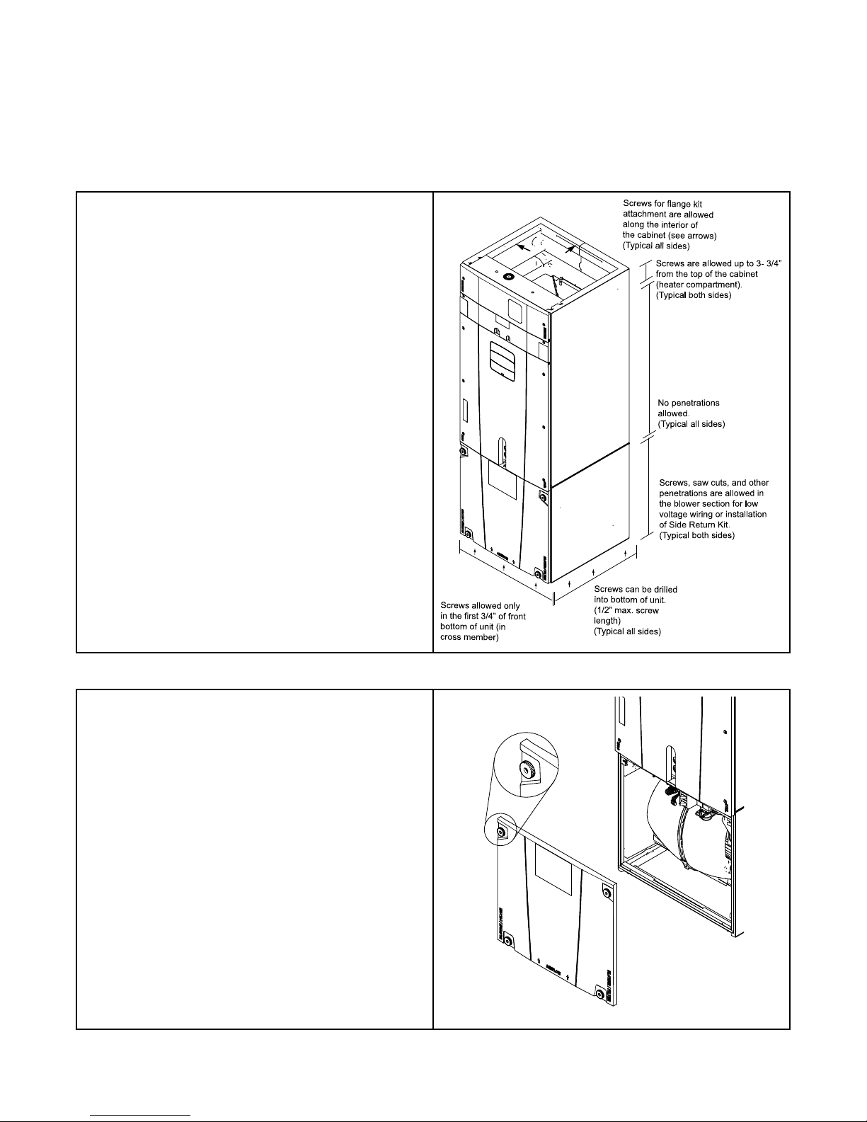
Screws ca n be drilled
into bottom of unit.
(1/2” max. s crew
length)
(Typical all sides)
Screws , saw cuts, and other
penetrations are a llowed in
the blower se ction for low
voltage wiring or installat
io
n
of Side Return Kit.
(Typical both sides)
Screws are a llowed up to 3- 3/4”
from the top of the ca bine t
(heate r compartment).
(Typical both sides)
Screws for flange kit
attachment are allowe
d
along the inte rior of
the cabinet (se e arrows )
(Typical all sides)
No penetrations
allowe d.
(Typical all sides)
Screws allowe d only
in the first 3/4” of front
bottom of unit (in
cross member)
Table 1. Cabinet Penetration
Important: Due to the unique design of this unit, which allows the
electrical wiring to be routed within the insulation, do not
screw, cut, or otherwise puncture the unit cabinet in any
location other than the ones illustrated.
Important: Under no conditions should metal strapping be attached
to the unit to be used as support mechanisms for
carrying or suspension purposes.
Table 2. Panel Removal
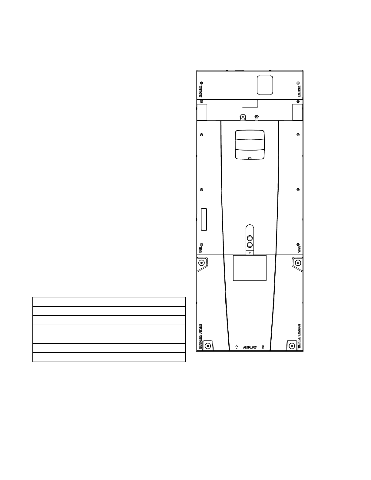
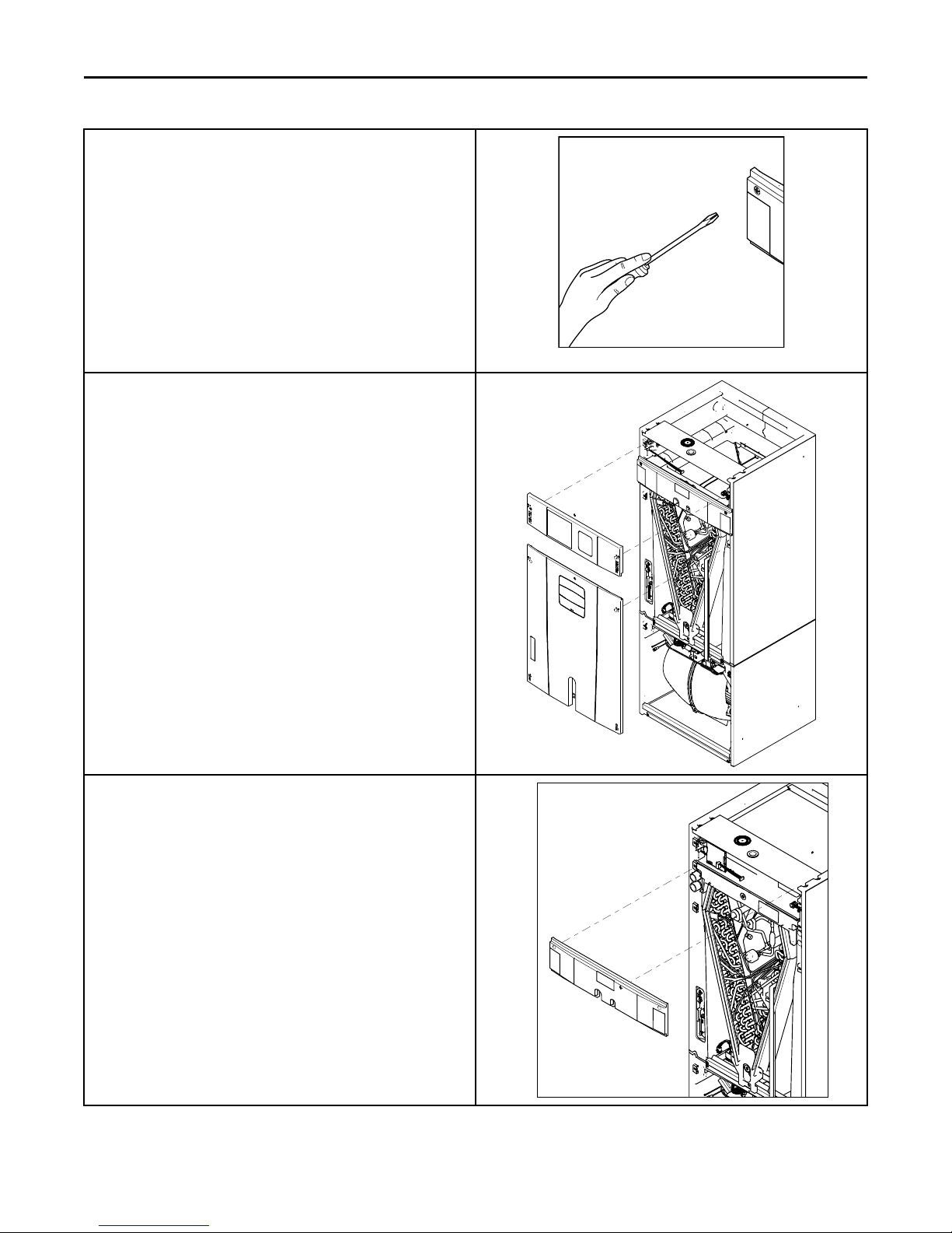
The unit contains four (4) access panels: Blower/Filter, Coil, Line Set,
and Heater.
The Blower/Filter panel is removed using 1/4 turn thumb screws.
1. Turn thumb screws on Blower/Filter panel.
2. Pull top of panel out, away from cabinet.
3. Lift panel up out of channel.
4. Set aside.
18-GJ06D2-2E-EN
5
Page 6
0
0
0
0
UUnniitt DDeessiiggnn
The Coil, Line Set, and Heater panels are removed using Phillips head
screws.
Removal requires #3 Size Phillips
Coil and Heater panels must be removed prior to removing the Line
Set panel.
To remove Coil Panel:
1. Turn screws on Coil panel.
2. Pull bottom of panel out, away from cabinet.
3. Pull panel down and out of channel.
4. Set aside.
To remove Heater Panel:
1. Turn screws on Heater panel.
2. Pull panel straight out, away from cabinet.
3. Set aside.
Removal of the Line Set panel is required for all refrigerant line brazing
and some condensate line assembly depending on your orientation.
To remove Line Set panel:
1. Remove both Heater and Coil panels.
2. Turn screws on Line Set panel.
3. Pull panel straight out, away from cabinet.
4. Set aside.
Note: After replacing all panels, loosen the Line Set panel screws
approximately 1/4 — 1/2 turn. This will improve the seal
between the Heater Panel and Line Set panel.
6
18-GJ06D2-2E-EN
Page 7
Unit Install Preparation
1. Check for damage and report promptly to the carrier any damage
found to the unit.
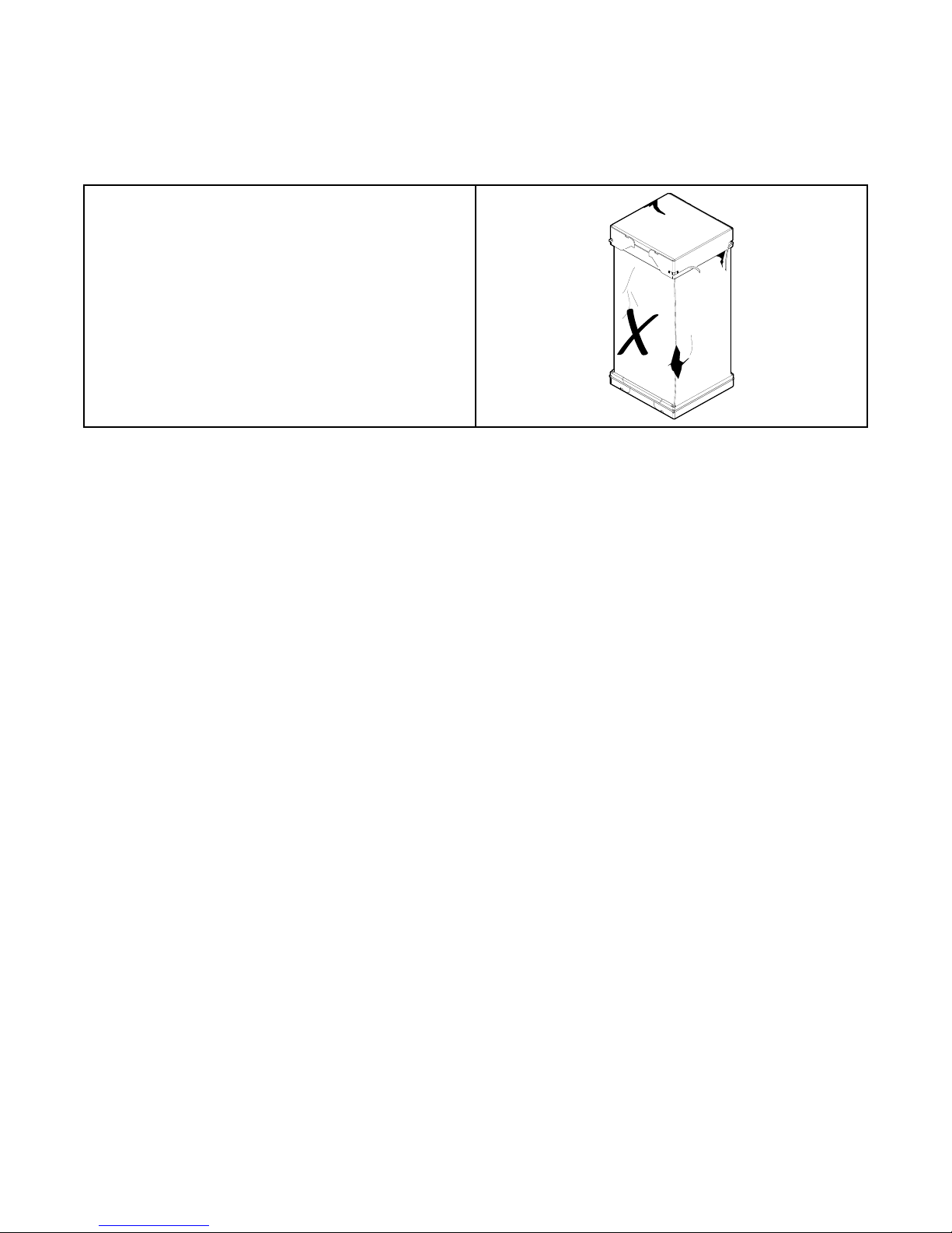
Note: If the unit must be transported in a horizontal position, it must
be laid on its back (marked “REAR” on carton).
Note: After unit is removed from the carton, verify coil is pressurized.
Carefully remove the liquid line plug. If no pressure is released,
check for leaks.
Note: Remove the cardboard from the bottom of the blower. Cut the
tie wrap and remove the foam shipping block located at the
motor.
18-GJ06D2-2E-EN
7
Page 8
Optional Equipment
Accessory Number Description
BAYEVAC04BK1AA
BAYEVAC04LG1AA
BAYEVAC05BK1AA
BAYEVAC05LG1AA
BAYEVAC08BK1AA
BAYEVAC08LG1AA
BAYEVAC10BK1AA
BAYEVAC10LG1AA
BAYEVBC15BK1AA
BAYEVBC20BK1AA
BAYEVCC25BK1AA
BAYEVAC10LG3AA
BAYEVBC15LG3AA
BAYSUPFLGAA
BAYSUPFLGBA
BAYSUPFLGCA
BAYRETFLGAA
BAYRETFLGBA
BAYRETFLGCA
BAYSRKIT100A Side Return Kit A to C
BAYFLR1620A
BAYFLR2020A
BAYFLR2220A
TASB175SB
TASB215SB
TASB235SB
MITISRKIT01A Side Return Kit with 16” x 20” Filter A to C
BAYFRKIT175 Front Return Kit for 17.5” Cabinet A
BAYFRKIT210 Front Return Kit for 21.0” Cabinet B
BAYFRKIT235 Front Return Kit for 23.5” Cabinet C
BAYBAFKT175A Sound Baffle Kit for 17.5” Cabinet A
BAYBAFKT215A Sound Baffle Kit for 21.0” Cabinet B
BAYBAFKT235A Sound Baffle Kit for 23.5” Cabinet C
TASSBK175 Sound Baffle Kit for 17.5” Cabinet A
TASSBK210 Sound Baffle Kit for 21.0” Cabinet B
TASSBK235 Sound Baffle Kit for 23.5” Cabinet C
BAYICSKIT01A Internal Condensate Switch Kit A to C
BAYHHKIT001A
BAYUVCLK001A
BAYLVKIT100A
BAYSPEKT200A
BAYWVAA05SC1AA
BAYWVBB07SC1AA
BAYWVCC08SC1AA
BAYWACC11SC1AA
BAYWVBRD485A RS-485 Control for BAYWACC11SC1AA C to C
BAYINSKT175A
BAYINSKT215A
BAYINSKT235A
BAYCNDPIP01A
Electric Heater, 4kW, Breaker, RS-485 Control, 1 Ph
Electric Heater, 4kW, Lugs, RS-485 Control, 1 Ph
Electric Heater, 5kW, Breaker, RS-485 Control, 1 Ph
Electric Heater, 5kW, Lugs, RS-485 Control, 1 Ph
Electric Heater, 8kW, Breaker, RS-485 Control, 1 Ph
Electric Heater, 8kW, Lugs, RS-485 Control, 1 Ph
Electric Heater, 10kW, Breaker, RS-485 Control, 1 Ph
Electric Heater, 10kW, Lugs, RS-485 Control, 1 Ph
Electric Heater, 15kW, Breaker, RS-485 Control, 1 Ph
Electric Heater, 20kW, Breaker, RS-485 Control, 1 Ph
Electric Heater, 25kW, Breaker, RS-485 Control, 1 Ph
Electric Heater, 10kW, Lugs, RS-485 Control, 3 Ph
Electric Heater, 15kW, Lugs, RS-485 Control, 3 Ph
Supply Duct Flange A
Supply Duct Flange B
Supply Duct Flange C
Return Duct Flange A
Return Duct Flange B
Return Duct Flange C
High Velocity Filter Kit, 16” x 20” x 1” (10 filters)
High Velocity Filter Kit, 20” x 20” x 1” (10 filters)
High Velocity Filter Kit, 22” x 20” x 1” (10 filters)
Plenum Stand with integrated sound baffle A
Plenum Stand with integrated sound baffle B
Plenum Stand with integrated sound baffle C
Horizontal Hanger Kit
UVC Lights
Low Voltage Conduit Entry Kit
Single Power Entry Kit
Hydronic Coil — 50,000 BTUH — Slide-in with control
Hydronic Coil — 70,000 BTUH — Slide-in with control
Hydronic Coil — 80,000 BTUH — Slide-in with control
Hydronic Coil — 100,000 BTUH — Add on
Solcoustic® Liner Kit for 17.5” cabinet
Solcoustic® Liner Kit for 21.5” cabinet
Solcoustic® Liner Kit for 23.5” cabinet
3/4” PVC Threaded Pipe Kit foam Seal (10 per box)
A to C
A to C
A to C
A to C
A to C
A to C
A to C
A to C
B to C
C
C
A to C
B to C
A
B
C
A
B
C
A
B
C
A
B
C
A to C
A to C
A to C
A to C
A to A
B to B
C to C
C to C
A
B
C
A to C
Fits Cabinet Size
8
18-GJ06D2-2E-EN
Page 9
Optional Cabinet Disassembly
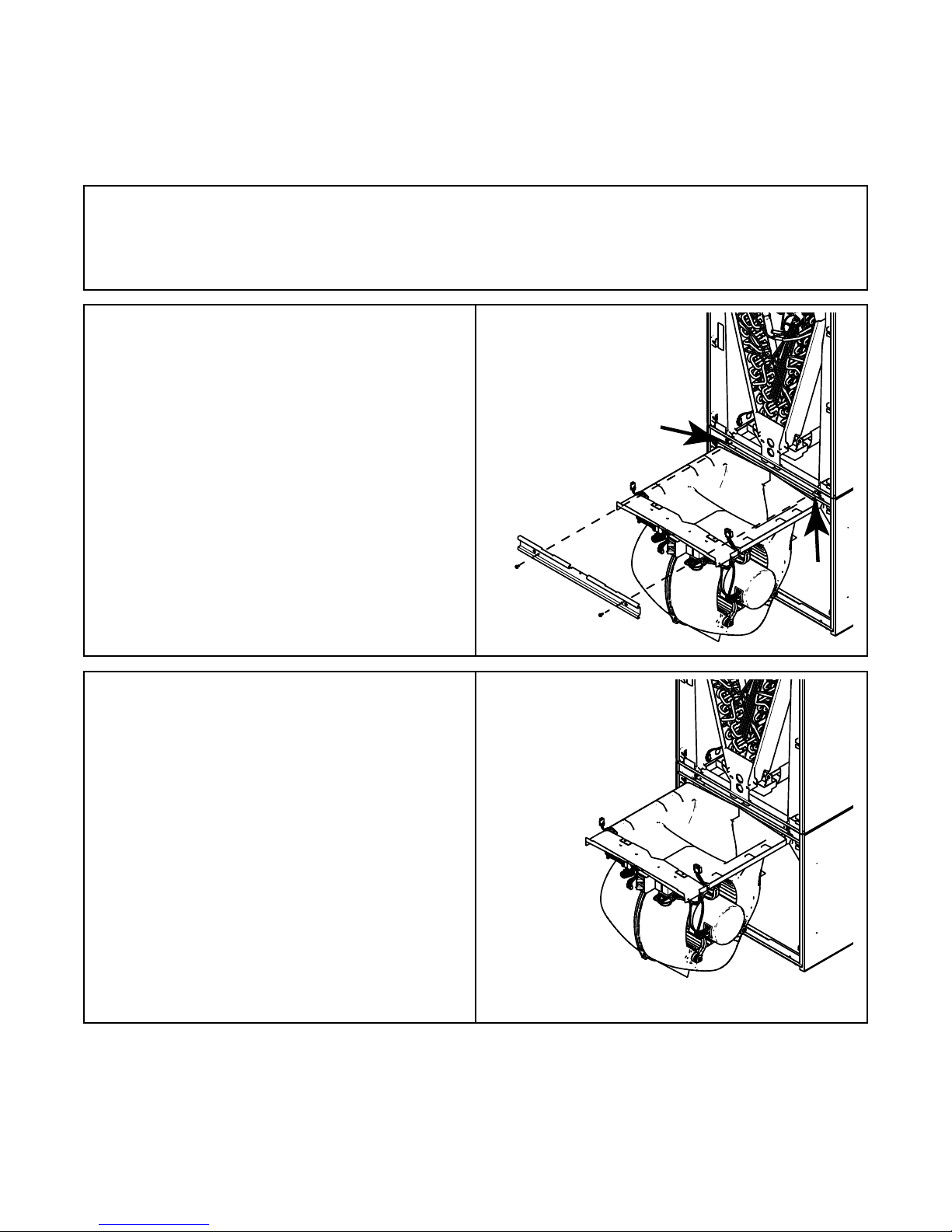
Note: If the unit must be transported in a horizontal position, it must be
laid on its back (marked “REAR” on carton).
Note: To reassemble cabinet, follow the steps in reverse order. Ensure
electrical connections are secure and the plug clips are engaged.
1. Remove all four front panels.
2. Remove the two screws on the seal bar and pull the seal bar
straight out.
3. Disconnect all wiring connections routed to the blower assembly.
See Table 2, p. 5
4. Slide Blower assembly out of unit using built-in blower support
channels and set aside.
Note: Remove the cardboard from the bottom of the blower. Cut the
tie wrap and remove the foam block located at the motor.
18-GJ06D2-2E-EN
9
Page 10
Coil Support
Channel
OOppttiioonnaall CCaabbiinneett DDiissaasssseemmbbllyy
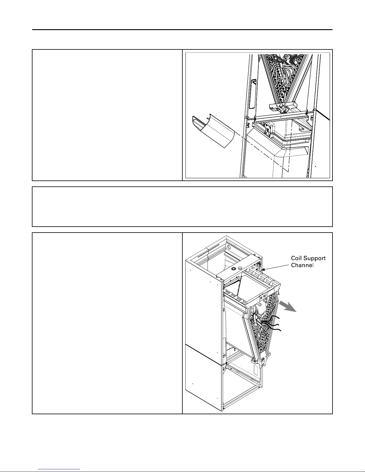
5. Remove airflow diverter from the bottom of coil drain pan by
gripping the plastic diverter while using your thumbs to spread
the top of the diverter slightly outwards and then pulling down
and out through the blower opening as illustrated.
6. Disconnect wires to the EEV motor and sensors. Cut the wire ties on
those wire harnesses if necessary and replace after re-installing.
Note: If cut, wire ties that held the sensor must be replaced after the coil is
placed back into the cabinet.
7. Slide Coil assembly out of unit using built-in coil support channels
and set aside
10
18-GJ06D2-2E-EN
Page 11
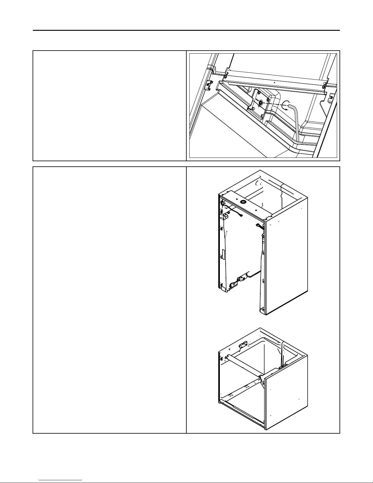
8. Use a 5/16 Allen wrench on the locking mechanism on each side
of the bottom half of the cabinet to loosen the locking mechanism.
The locks loosen by turning counter-clockwise approximately 3/4
of a turn.
9. Lift the Coil section up and away from the Blower section. Set
aside.
Note: When separating the two cabinet pieces, make sure the gasket
remains intact.
OOppttiioonnaall CCaabbiinneett DDiissaasssseemmbbllyy
18-GJ06D2-2E-EN
11
Page 12
OOppttiioonnaall CCaabbiinneett DDiissaasssseemmbbllyy
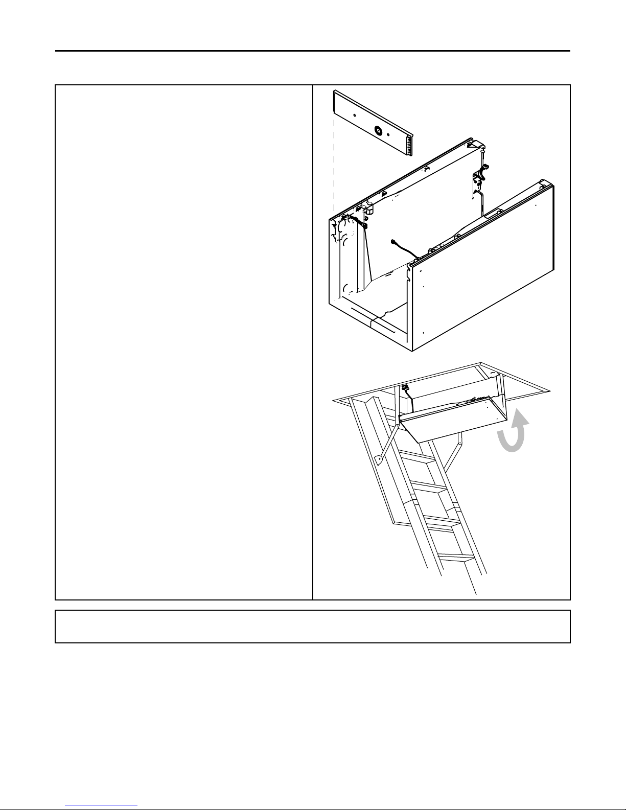
10. For extremely tight spaces where the cabinet needs to be rotated
through a small opening, remove the top panel and all cross
members. Use a manual driver to avoid stripping screw holes.
11. Continue preparation by following the proper carrying procedures shown in the next section.
12
18-GJ06D2-2E-EN
Page 13
Placing Unit at Location
Cross M em bers
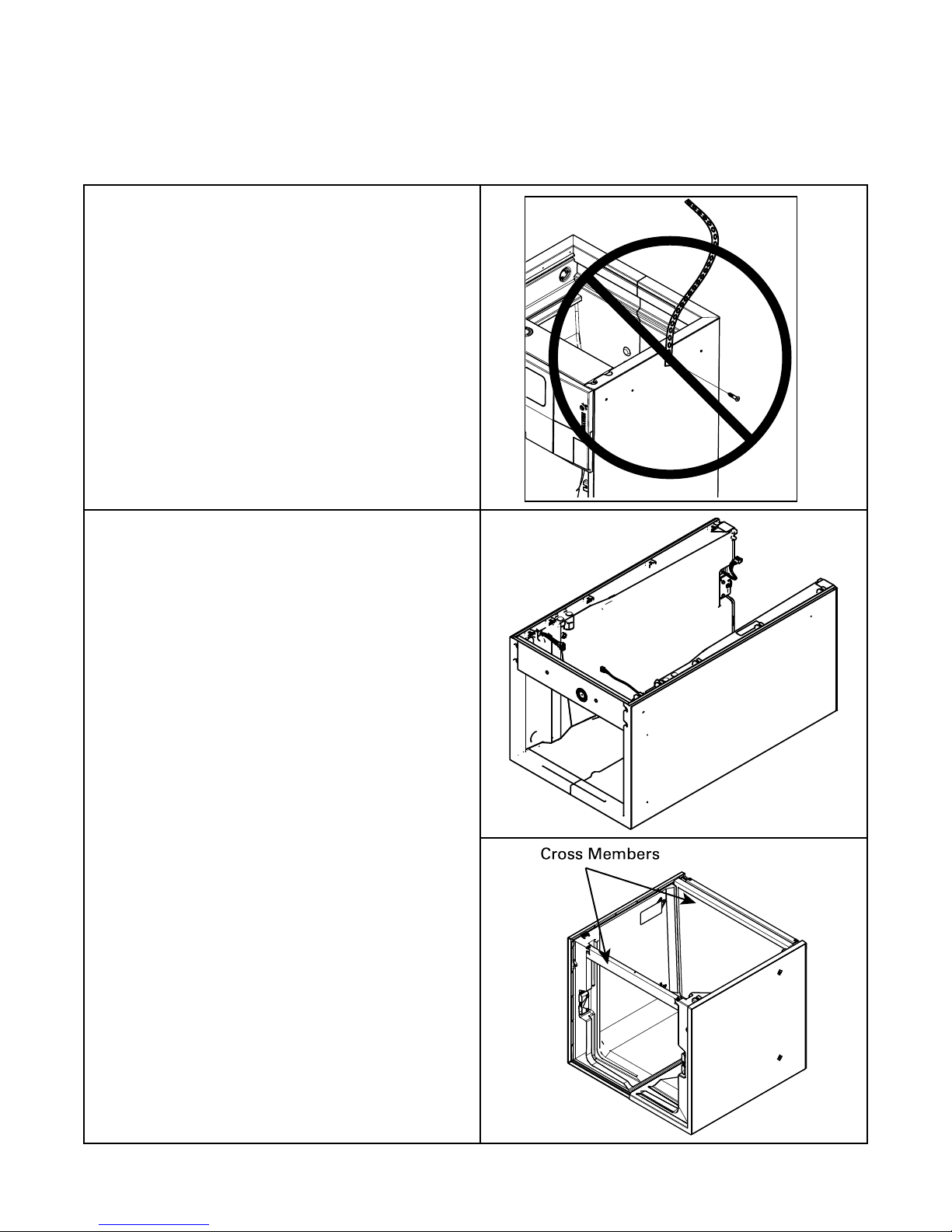
1. Carry the unit to the installation location
2. Reassembly by reversing the steps listed in Section 4 if
disassembly was required. If cut, wire ties that held the sensor
wiring must be replaced.
Important: Under no conditions should metal strapping be attached
Approved Carrying:
• Hold by the cross members within the cabinet or unit top plate and
to the unit to be used as support mechanisms for carrying
or suspension purposes.
use as handles for lifting and carrying the coil and blower sections.
18-GJ06D2-2E-EN
13
Page 14
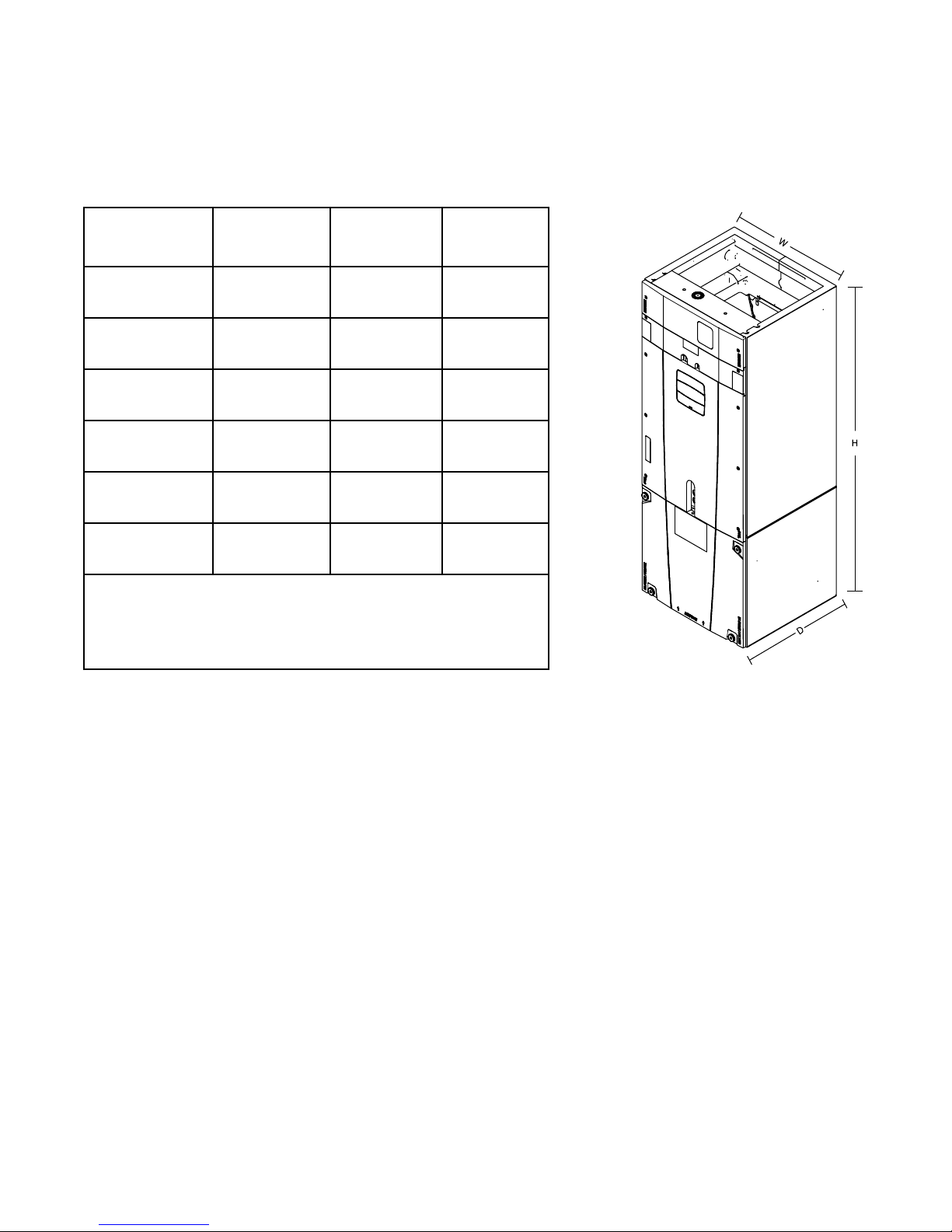
Unit Location Considerations
D
H
W
Table 3. Unit Dimensions and Weight
Coil and Heater
Compartment
Height *
(inches)
Unit Net Weight
(pounds)
MODEL NUMBER
H x W x D
(inches)
TAM7A0A24H21SD
TAM7A0A24H21EA
TAM7A0B30H21SD
TAM7A0B30H21EA
TAM7A0C36H31SD
TAM7A0C36H31EA
TAM7A0C42H31SD
TAM7A0C42H31EA
TAM7A0C48H41SD
TAM7A0C48H41EA
TAM7B0C60H51SC
TAM7B0C60H51EA
* Blower compartment height is 21.8 inches.
49.9 x 17.5 x 21.8 28.1 120
55.7 x 21.3 x 21.8 33.9 133
56.9 x 23.5 x 21.8 35.1 143
56.9 x 23.5 x 21.8 35.1 158
61.7 x 23.5 x 21.8 39.9 174
61.7 x 23.5 x 21.8 39.9 178
14
18-GJ06D2-2E-EN
Page 15
Air ow
Up ow Con guration
Refrigerant
Connections
Low Voltage
Connections
Inside Unit
Control
Pocket
Inside Unit
Upo w
Condensate Drains
Low Voltage
Connections
Inside Unit
Control Pocket
Inside Unit
Refrigerant
Connections
Down ow Conden-
sate Drains
Four-Way Conversion
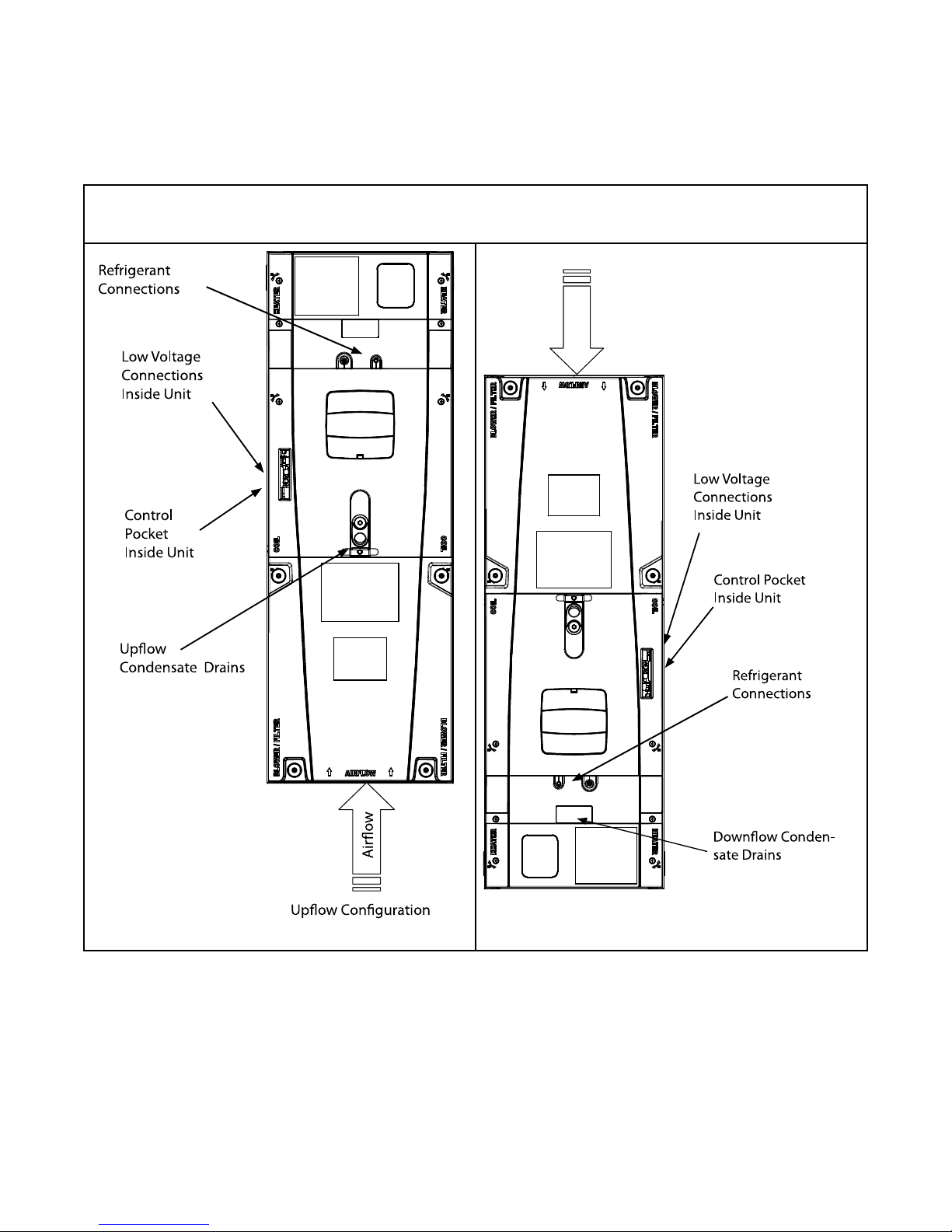
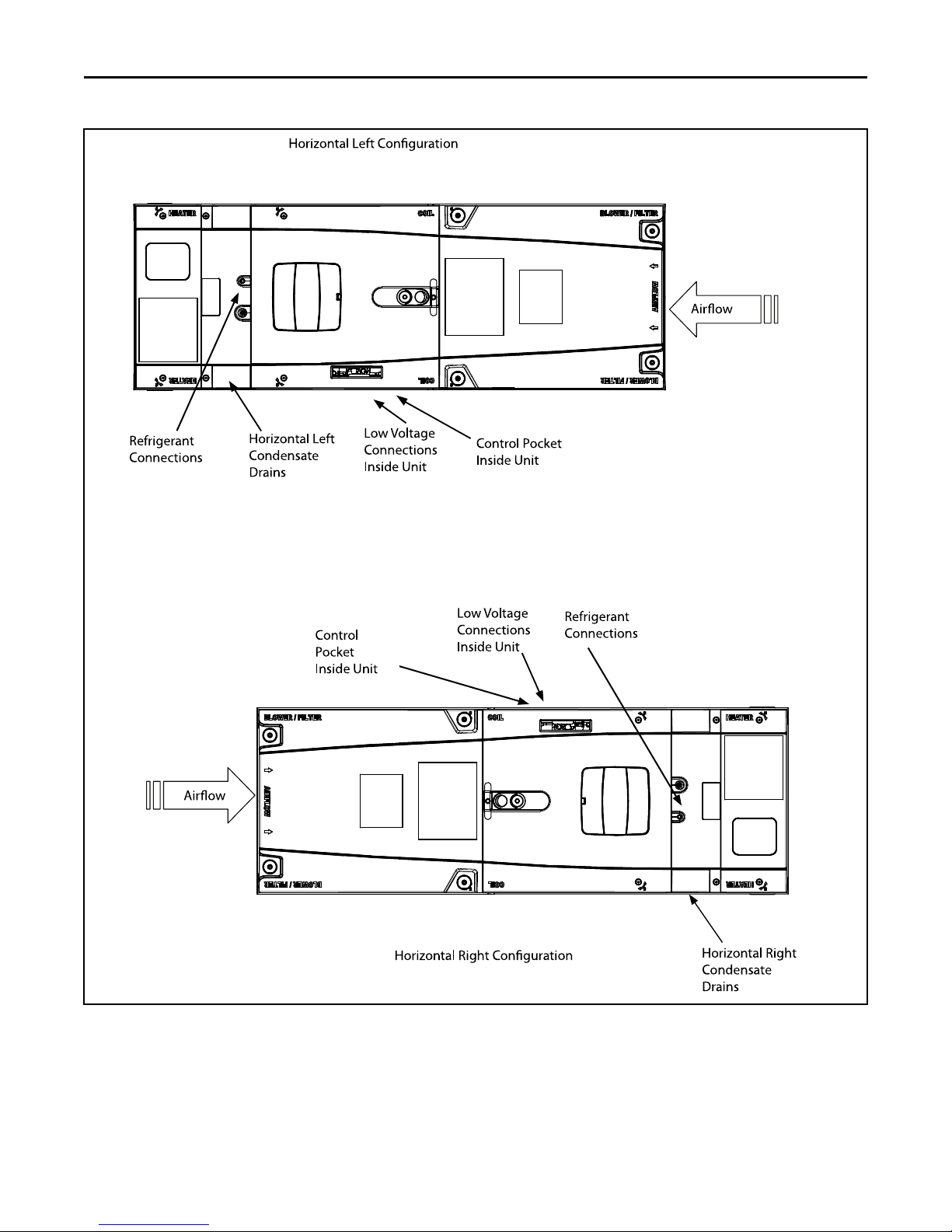
To place the unit in the configuration your application requires (upflow, downflow, horizontal right, or horizontal left), simply turn the unit to
that orientation. Remember to adjust the badge accordingly.
Note: The air handlers are shipped from the factory suitable for four-way application.
18-GJ06D2-2E-EN
15
Page 16
Air ow
Refrigerant
Connections
Horizontal Left
Condensate
Drains
Low Voltage
Connections
Inside Unit
Control Pocket
Inside Unit
Horizontal Left Con guration
Horizontal Right Con guration
Air ow
Control
Pocket
Inside Unit
Low Voltage
Connections
Inside Unit
Refrigerant
Connections
Horizontal Right
Condensate
Drains
FFoouurr--WWaayy CCoonnvveerrssiioonn
16
18-GJ06D2-2E-EN
Page 17
Ducted and Non-Ducted Applications
Suppl y Duct
Plenum
Accessor y with
Safety Guard
Non-Ducted
Return
Suppl y Duct
Return Duct
Ducted Return
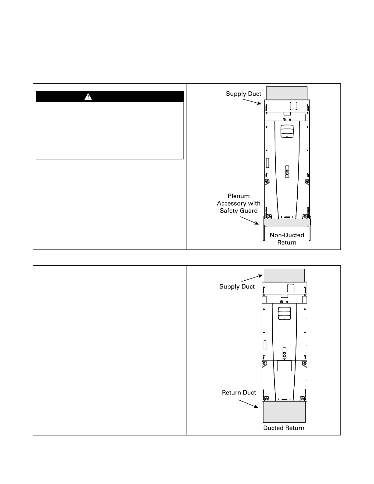
Table 4. Non-Ducted Applications
CCAAUUTTIIOONN
HHAAZZAARRDDOOUUSS VVAAPPOORRSS!!
FFaaiilluurree ttoo ffoollllooww tthhiiss CCaauuttiioonn ccoouulldd rreessuulltt iinn
pprrooppeerrttyy ddaammaaggee oorr ppeerrssoonnaall iinnjjuurryy..
HHaazzaarrddoouuss vvaappoorrss ccaann bbee ddiissttrriibbuutteedd tthhrroouugghhoouutt tthhee
ccoonnddiittiioonneedd ssppaaccee aanndd eeqquuiippmmeenntt ddaammaaggee ccaann
rreessuulltt.. DDoo nnoott iinnssttaallll aann aaiirr hhaannddlleerr wwiitthh aa nnoonn-dduucctteedd rreettuurrnn iinn tthhee ssaammee cclloosseett,, aallccoovvee,, oorr uuttiilliittyy
rroooomm aass aa ffoossssiill ffuueell ddeevviiccee..
Non-Ducted Return Installations:
• Installation in a closet, an alcove, or a utility room without a
return duct requires the use of a plenum accessory kit as it uses
the area space as a return air plenum. Minimum clearances to
combustible materials and service access must be observed (see
outline drawing).
• This area may also be used for other purposes, including an
electric hot water heater, but in no case shall a fossil fuel device be
installed and/or operated in the same closet, alcove, or utility
room.
• Review local codes to determine limitations if the unit is installed
without a return air duct.
Table 5. Ducted Return Installations.
Ducted Return Installations:
• Installation in an attic, garage, or crawl space with ducted supply
and return air is appropriate. Minimum clearances to combustible
materials and service access must be observed (see outline
drawing).
18-GJ06D2-2E-EN
17
Page 18

Additional Unit Preparation Considerations
For proper installation the following items must be
considered prior to moving the unit to its installation
site:
• Pursuant to Florida Building Code 13–610.2A.2.1,
this unit meets the criteria for a factory sealed air
handler.
• If a side return is needed for your application, the
side return MUST be prepared prior to moving the
air handler to its installation location. See the Side
Return Kit #BAYSRKIT100A Installer Guide for
detailed instructions, if used.
• When the air handler is located adjacent to the
living area, the system should be carefully designed
with returns which minimize noise transmission
through the return air grill. Although the air handler
is designed with large blowers operating at
moderate speeds, any blower moving a high
volume of air will produce audible noise which
could be objectionable when the unit is located very
close to a living area. It is often advisable to route
the return ducts under the floor through the attic.
Such design permits the installation of air return
remote from the living area (i.e. central hall).
• Study the unit’s outline drawing and dimensions
prior to selecting the installation site. Note in
advance which electrical conduit entry points and
condensate drain holes are to be used, so that
proper clearance allowances can be made for
installation and future maintenance.
• Installation of the air handler must be made prior to
, or at the same time as, the installation of the
outdoor unit in order to allow access for refrigerant
lines.
• Consider the overall space needed when external
accessories are used, additional height and width
requirements may exist.
• These units are not approved for outdoor
installation.
• These units must be installed in the proper air flow
direction.
• Any third-party heater accessories or hydronic coils
must be downstream of the unit.
NNoottee:: No atomizing style humidifier is allowed in the
return plenum with the use of this unit.
• Excessive bypass air may cause water blow-off,
which will adversely affect system operation and air
cleaner performance. To verify bypass airflow,
follow the Bypass Humidifier Pre-Installation
Checkout and Set-Up Procedures available through
your local distributor. Ask for publication number
18–CH37D1–* Steam and Flow-through Fan Power
Duct-mounted Humidifiers. Follow the humidifier
installation instructions. These should only be
installed on the supply air side of the system.
NNoottee:: The air handlers have been evaluated in
accordance with the Code of Federal Regulations,
Chapter XX, Part 3280 or the equivalent.
“SUITABLE FOR MOBILE HOME USE.”
NNoottee:: TThhiiss uunniitt iiss cceerrttiiffiieedd ttoo UULL 11999955.. TThhee iinntteerriioorr
ccaabbiinneett wwaallll mmeeeettss tthhee ffoolllloowwiinngg::
— UL94–5VA Flame Class Listed
— UL723 Steiner Tunnel Listed for 25/50 Flame/Smoke
— UL746C Listed for Exposure to Ultraviolet Light,
Water Exposure and Immersion
18
18-GJ06D2-2E-EN
Page 19
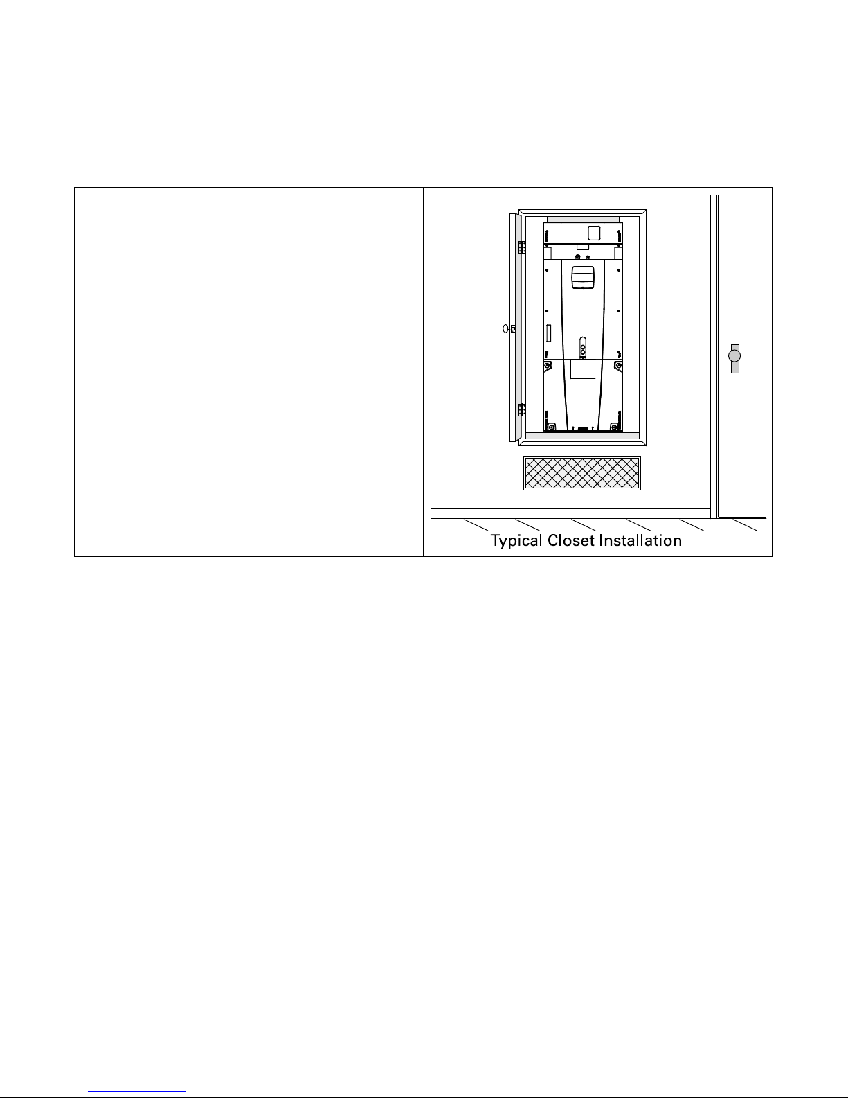
Setting the Unit — Vertical Installation
Typical Closet Installation
Table 6. Considerations
Provide a minimum height of 14 inches for proper unrestricted airflow
below the unit. Allow a minimum of 21 inches clearance in front of the
air handler to permit maintenance and removal of filter.
• Position unit on suitable foundation. If a manufacturer approved
accessory is not used, a frame strong enough to support the total
weight of the unit, accessories, and duct work must be provided.
• Isolate unit from the foundation using a suitable isolating
material.
Note: The following sound insulation kits are available to lessen
objectionable sound.
BAYINSKT175A for use with 17.5” cabinets
BAYINSKT215A for use with 21.5” cabinets
BAYINSKT235A for use with 23.5” cabinets
18-GJ06D2-2E-EN
19
Page 20

Airflow
Airflow
Typical TASB Installation
Airflow
A
irflow
Typical Plenum Installation
SSeettttiinngg tthhee UUnniitt —— VVeerrttiiccaall IInnssttaallllaattiioonn
Table 7. Upflow Installation
TASB Installation
1. Install the TASB plenum stand with integrated sound baffle using
the TASB instructions.
Note: Kit is used for open air applications.
TASB175SB for use with 17.5” cabinets
TASB215SB for use with 21.5” cabinets
TASB235SB for use with 23.5” cabinets
MITISRKIT1620 — Side return kit with 16” x 20” filter
Contact your distributor for more information.
Note: The following sound insulation kits are available to lessen
objectionable sound.
BAYINSKT175A for use with 17.5” cabinets
BAYINSKT215A for use with 21.5” cabinets
BAYINSKT235A for use with 23.5” cabinets
Table 8. Plenum Installation
2. Assemble the plenum using the plenum’s Installer Guide.
On units with sheet metal returns: Return plenum must be flanged.
Sheet metal drill point screws must be 1/2” in length or shorter.
20
18-GJ06D2-2E-EN
Page 21
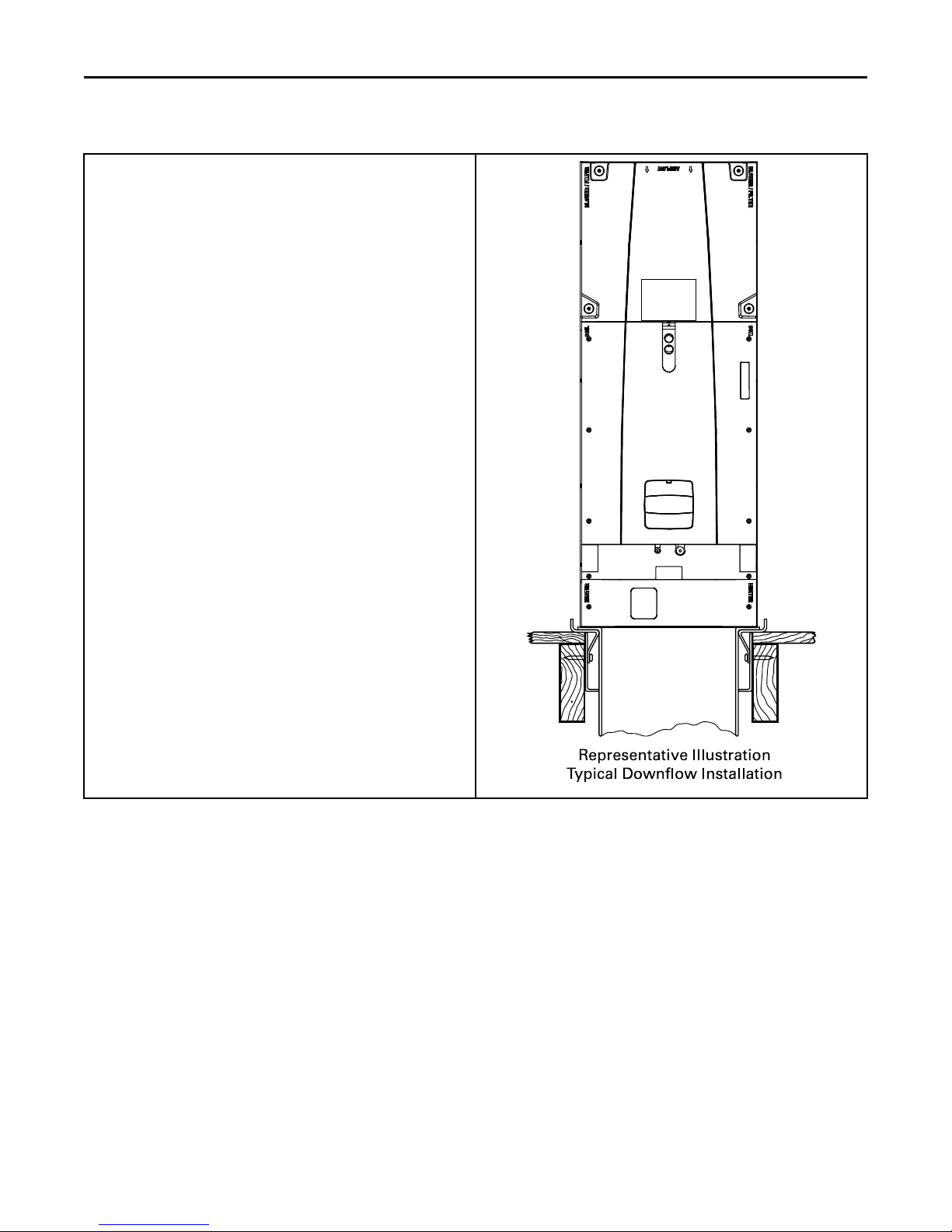
Table 9. Downflow Installation
Representative Illustration
Typical Downflow Installation
• Downflow installation must comply with national, state, and local
codes.
• The air handlers are rated for zero clearance from combustible
materials.
3. Prepare the location site as appropriate for your application and
per national, state, and local code requirements.
4. Set the unit in position.
SSeettttiinngg tthhee UUnniitt —— VVeerrttiiccaall IInnssttaallllaattiioonn
18-GJ06D2-2E-EN
21
Page 22
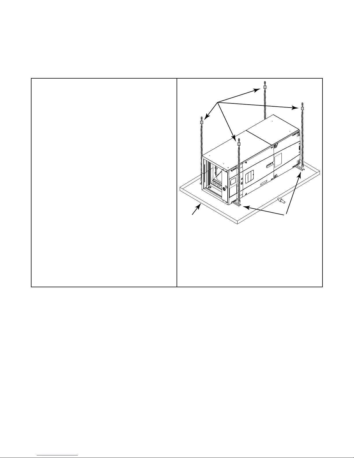
Setting the Unit — Horizontal Installations
Auxiliary Drain
Pan
Bottom Support
Near Both Ends
Field Supplied
Isolators
Table 10. Considerations
Important: Due to the unique design of this unit, which allows the
electrical wiring to be routed within the insulation , do not
screw, cut, or otherwise puncture the unit cabinet in any
location other than the ones illustrated in this Installer
Guide or in an approved accessory’s Installer Guide.
Important: Make certain that the unit has been installed in a level
position to ensure proper draining.
Important: Under no conditions should metal strapping be attached
to the unit to be used as support mechanisms for
carrying or suspension purposes.
1. Support the unit from the bottom (near both ends). The service
access must remain unobstructed.
a. Approved bottom support methods are rail, u-channels
(Unistrut ®), or other load bearing materials.
b. The unit must be isolated carefully to prevent sound
transmission. Field supplied vibration isolators are
recommended.
Important: The unit can only be supported from the bottom unless
using kit BAYHHKIT001A. Do not drill or screw supports
into any area of the cabinet.
Note: Do not allow the unit to be used as strain relief.
2. Install an auxiliary drain pan under the horizontal air handler to
prevent possible damage to ceilings.
3. Install an auxiliary drain pan under the horizontal air handler to
prevent possible damage to ceilings.
a. Isolate the auxiliary drain pan from the unit and from the
structure.
b. Connect the auxiliary drain pan to a separate drain line and
terminate according to local codes.
Note: BAYHHKIT001A Hanging Bracket Kit may be ordered
separately.
Important: The BAYHHKIT001A may not be used if the cabinet has
been altered per Installer Guide 18–GJ58D1–1
22
18-GJ06D2-2E-EN
Page 23
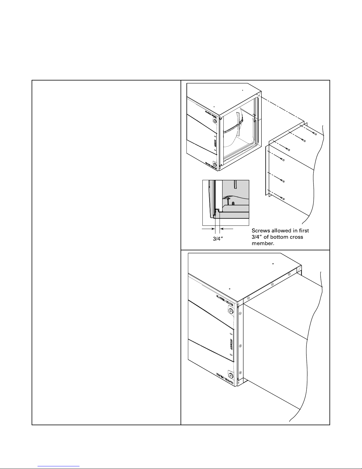
Connecting the Duct work
3/4”
Screws allowed in first
3/4” of bottom cross
member.
Table 11. Duct Connection Considerations
Important: Due to the unique design of this unit, which allows the
Important: Under no conditions should metal strapping be attached
Important: On units with sheet metal returns: Return air plenum
• The supply and return air ducts must be connected to the unit
• See the Outline drawing for sizes of the duct connections.
• After the ducts are secured, seal around the supply and return
• Insulate all duct work that will be outside of conditioned spaces.
• Convertible Duct Flange Kits are available to connect the supply
• If front or rear return is required, the air handler must be elevated
• If side return is required, the Side Return Kit # BAYSRKIT100A
• To ensure maximum efficiency and system performance, the
electrical wiring to be routed within the insulation, do not
screw, cut, or otherwise puncture the unit cabinet in any
location other than the ones illustrated in this Installer
Guide or in an approved accessory’s Installer Guide.
to the unit to be used as support mechanisms for
carrying or suspension purposes..
must be flanged. Sheet metal drill point screws must be
1/2” in length or shorter.
with non flammable duct connectors.
ducts to prevent air leakage.
plenum or for mounting on the discharge opening to provide a
“flush fit” for 1–1/2” duct board applications.
— placed on a pedestal or plenum and duct must be connected to
this pedestal or plenum.
accessory must be used. A remote filter will be required.
existing supply and return duct system static pressures must not
exceed the total available static pressure of the air handler.
Reference ACCA Manual D, Manual S and Manual RS along with
the air handler Product Data and Service Facts for additional
information.
Note: Side return is not approved without Side Return Kit #
BAYSRKIT100. More than one Side Return Kit may be
necessary depending on the application. Refer to the
Installation Guide in BAYSRKIT100 for approved duct
connections, sizing, number, transitions, and accessory
application.
Note: Duct work must be supported as appropriate. See National and
local codes for guidelines. Do not depend on the unit to support
duct work.
18-GJ06D2-2E-EN
23
Page 24
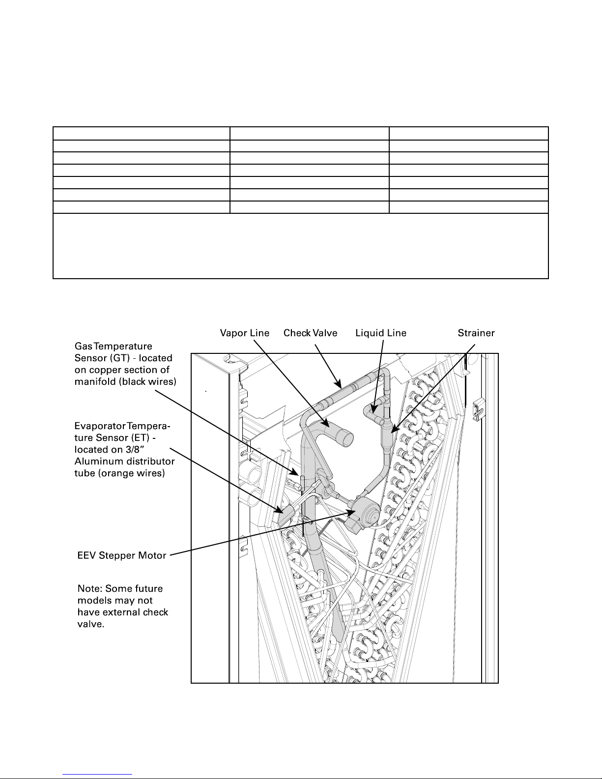
Refrigerant Line
Vapor Line Chec k Valve Liquid Line Str ainer
Gas Tem perature
Sensor (GT) - located
on copper section of
mani fold (black wires)
Evapor ator Tempera-
tur e Sensor (ET) -
located on 3/8”
Aluminum distributor
tube (orange wires)
EEV Stepper Motor
Note: Some future
model s may not
have exter nal check
valve.
Table 12. Refrigerant Line Connection Sizes
Model
TAM7A0A24H21SD, TAM7A0A24H21EA
TAM7A0B30H21SD, TAM7A0B30H21EA
TAM7A0C36H31SD, TAM7A0C36H31EA
TAM7A0C42H31SD, TAM7A0C42H31EA
TAM7A0C48H41SD, TAM7A0C48H41EA
TAM7B0C60H51SC, TAM7B0C60H51EA
Notes:
1. This table indicates the tubing connection diameters at the indoor coil. A field supplied reducing coupling may be required.
2. All AHRI listed systems are tested with 25 feet of refrigeration tubing; the rated tubing diameters are located in the electronic performance
data system.
3. If the refrigeration lines exceed 60 feet in linear length and/or if alternate size refrigeration tubing is present at the job, please consult SSAPG006–EN or 32–3312** (latest version)
Refrigerant System Layout
Vapor Line Connection Liquid Line Connection
3/4 3/8
3/4 3/8
7/8 3/8
7/8 3/8
7/8 3/8
7/8 3/8
24
18-GJ06D2-2E-EN
Page 25
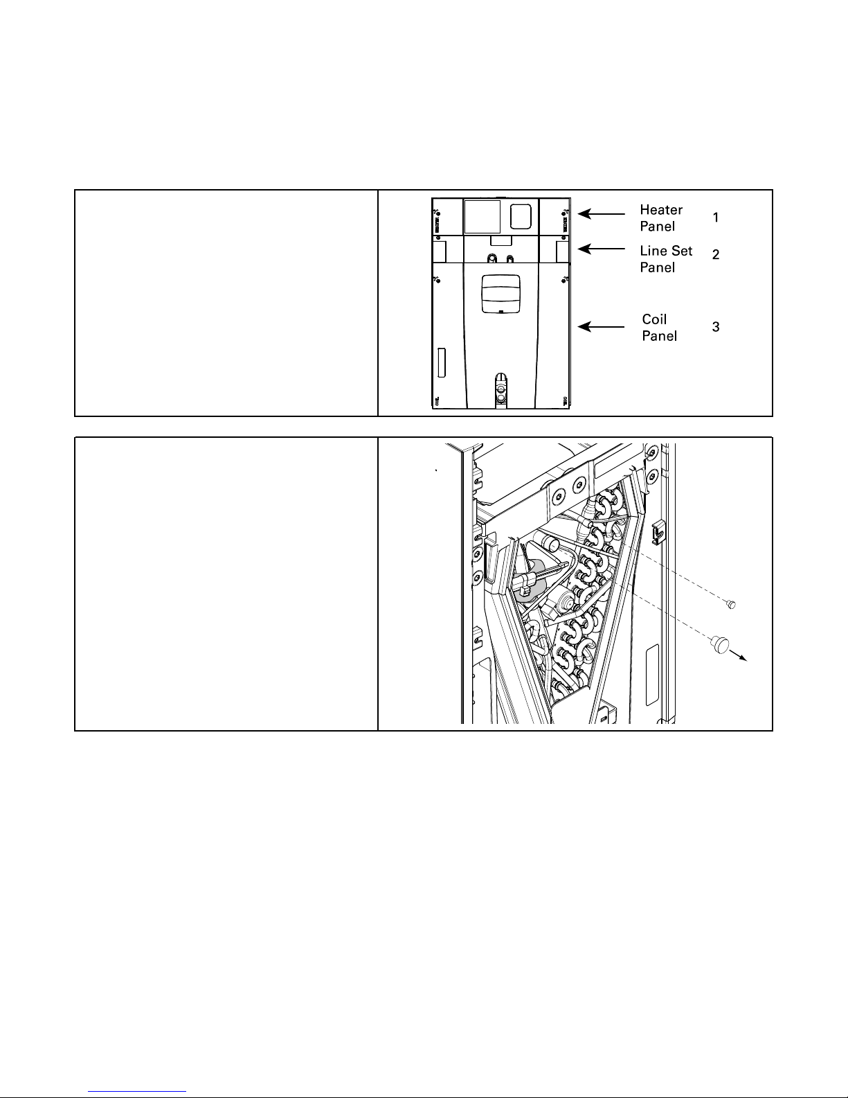
Refrigerant Line Brazing
Heater
Panel
Line Set
Panel
Coil
Panel
1
2
3
Table 13. Braze the Refrigerant Lines
1. Remove Heater, Coil, and Line Set panels.
See Table 2, p. 5
Important: Do NOT unseal coil refrigerant connection stubs
Important: Heat Sensitive Sensors. The Gas Temperature
2. Remove the sealing plug from the indoor coil suction
3. Remove the sealing plug from the indoor coil liquid line.
This coil is pressurized with 8–12 psig of dry air. Do not
stand directly in front of the coil connections when removing
sealing plugs.
until ready to make connections.
Sensor must be removed or a wet rag must be
wrapped around the suction line between the
Sensor and the braze joint to protect it from
failure due to overheating.
line.
18-GJ06D2-2E-EN
25
Page 26
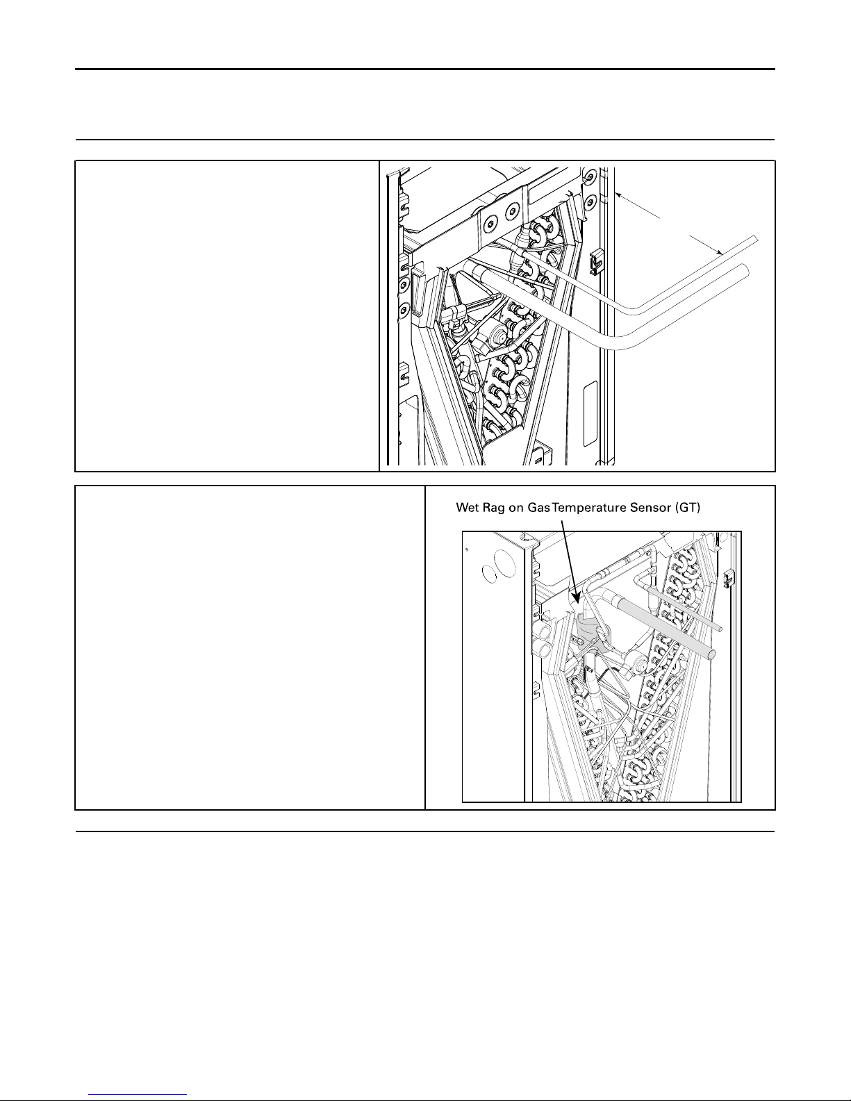
1.5” MIN
Wet Rag on Gas Temperature Sensor (GT)
RReeffrriiggeerraanntt LLiinnee BBrraazziinngg
Table 13. Braze the Refrigerant Lines (continued)
4. Connect, but do not braze field line set to indoor coil.
a. Allow a minimum of 1.5 inches of refrigerant line set
before using an elbow coupling.
Important: Service access to the auxiliary heater must
Important: Heat Sensitive Sensor. The temperature Sensor must be
5. Braze refrigerant line connections.
Note: The suction line must be insulated prior to brazing the line set
remain unobstructed.
removed or a wet rag must be wrapped around the
suction line between the Sensor and the braze joint to
protect the Sensor from failure due to overheating.
a. Pull back the insulation before brazing the suction line.
b. Wrap the Gas Temperature Sensor (GT) with a wet rag.
c. Braze the refrigerant line connections.
to the air handler stubs.
26
18-GJ06D2-2E-EN
Page 27
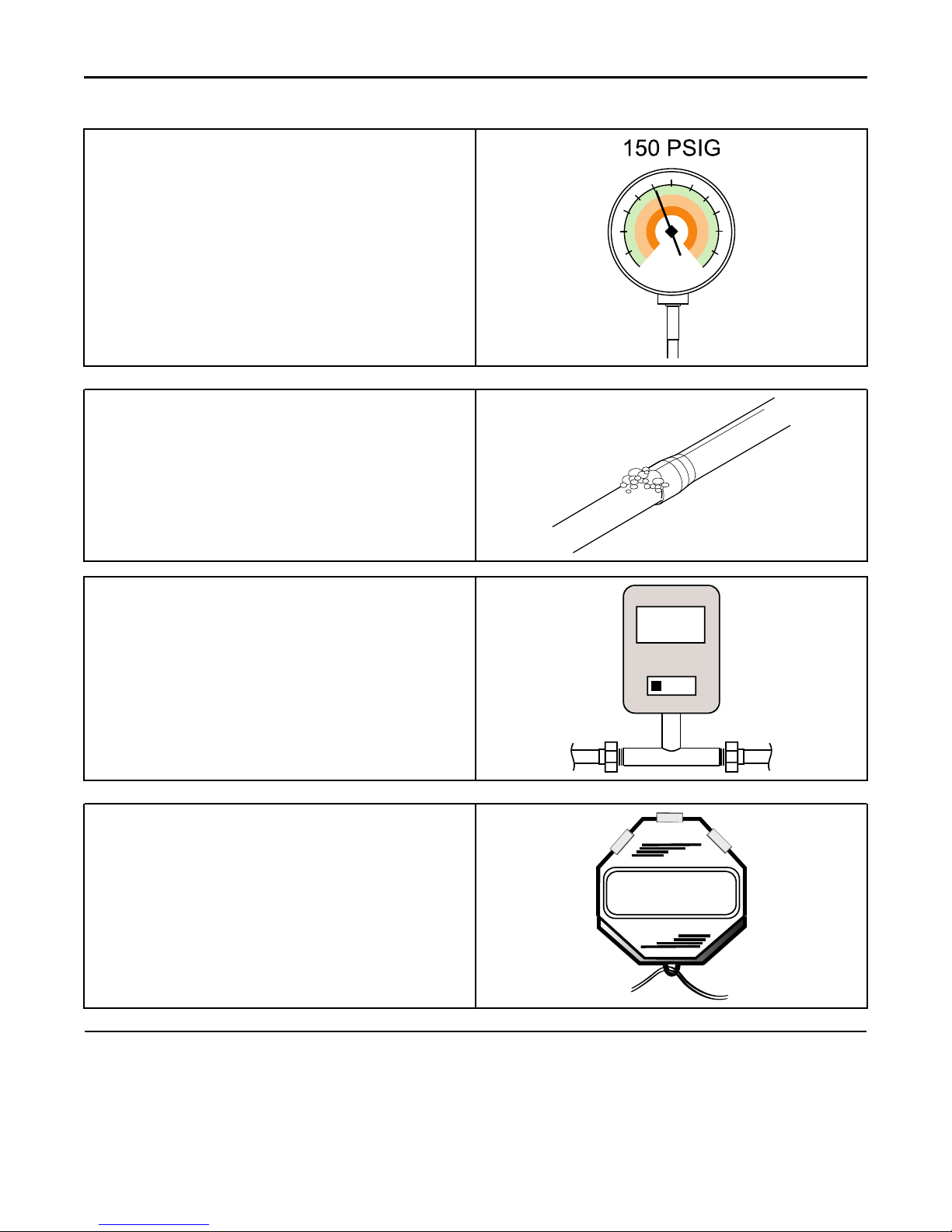
6. Pressurize the refrigerant lines and evaporator coil to 150 PSIG
150 PSIG
0350
Microns
ON
OFF
1 MIN.
using dry nitrogen.
7. Check for leaks by using a soapy solution or bubbles at each
brazed location.
RReeffrriiggeerraanntt LLiinnee BBrraazziinngg
Important: Do not open the service valves until the refrigerant lines
and indoor coil leak check and evacuation are complete.
8. Evacuate until the micron gauge reads no higher than 350
microns, then close off the valve to the vacuum pump.
9. Observe the micron gauge. Evacuation is complete if the micron
gauge does not rise above 500 microns in one (1) minute.
a. Once evacuation is complete blank off the vacuum pump and
micron gauge, and close the valves on the manifold gauge
set.
Note: Charge system using Outdoor unit’s Installer Guide or Service
Facts.
Note: Ensure to wipe any refrigerant oil off the panels.
18-GJ06D2-2E-EN
27
Page 28
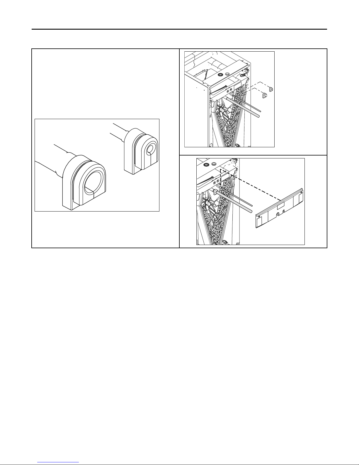
RReeffrriiggeerraanntt LLiinnee BBrraazziinngg
10. Replace the Line Set panel.
a. Allow time for tubing to cool.
b. Install grommets to line set piping in orientation shown.
c. Allow time for tubing to cool.
d. Install grommets to line set piping in orientation shown.
Note: A slight amount of dish soap can be used to aid in the
installation of the grommets. Remove any excess from the
tubing and grommet after the grommet is installed.
ILLUSTRATION FOR ORIENTATION
SEE ENLARGED
28
18-GJ06D2-2E-EN
Page 29
Condensate Drain Piping
Table 14. Condensate Drain Piping Considerations
• Condensate drain plumbing must comply with national, state, and
local codes.
• Route condensate drain lines away from air handler so they do not
interfere with access panels.
• Slope the drain lines downward a minimum of 1/4” per foot,
support per local codes.
• Do not use reducing fittings in the condensate drain lines.
• Do not connect the drain line to a closed drain system.
• Do not use a torch or flame near the plastic drain pan coupling.
• A P-trap is not required for proper drainage due to the positive
pressure of the air handler; however, it is recommended to
prevent efficiency loss of conditioned air.
18-GJ06D2-2E-EN
29
Page 30
S P
S
P
S
P
S
P
Downflow
Condensate
Drains
Horizontal Left
Condensate Drains
Horizontal Right
Condensa te Drains
Upflow
Condensate
Drains
Air seal
over
secon dary
drain
PVC
CEMENT
Teflon Tape
Drain Nipple
3/4” PVC Pipe
PVC/CPVC Cement
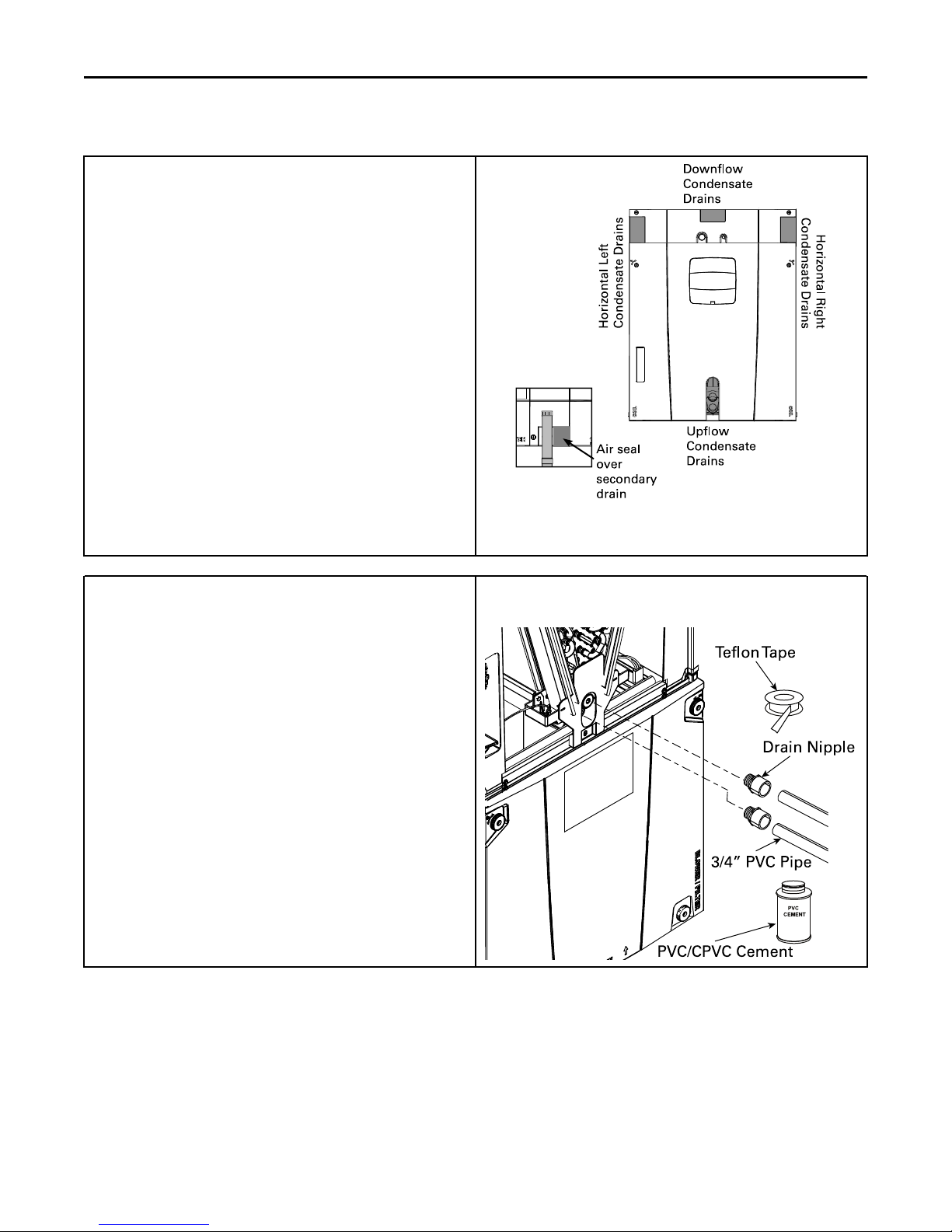
CCoonnddeennssaattee DDrraaiinn PPiippiinngg
Table 15. Connect Condensate Drain Piping
Note: Downflow and horizontal orientations require the Coil panel to
be removed in order to make the drain connections.
Note: Make certain that the unit has been installed in a level position
to allow for proper draining.
1. Select the drain connections that are oriented for your
application.
2. Prepare the condensate drain connections.
a. From the factory, the unit comes with plugs in both upflow
condensate drains and an additional plug in the
documentation packet.
b. For upflow applications, remove upflow condensate plug(s)
and connect condensate piping.
c. For all other applications, do not remove upflow condensate
plugs. Remove the cover from the needed condensate drain
connections and connect condensate piping.
d. If the secondary condensate opening is not used, plug the
condensate opening with the fitting supplied in the
documentation pack. Use scissors to cut the air seal in half
and re-install over the unused opening.
• Dry fit and test clearance for coil panel removal before applying
PVC/CPVC cement.
• Use Teflon tape on the air handler drain line connections. Do not
use pipe joint compound or PVC/CPVC cement on drain nipple.
• Hand tighten the drain pipe.
3. For upflow installations, connect 3/4” PVC pipe to the threaded
drain nipple with PVC/CPVC cement. 3” minimum clearance to the
condensate piping is needed for coil panel removal. Thread the
assembly into the primary drain connection (repeat for the
secondary drain connection if used).
IMPORTANT: For Horizontal and Downflow installations, the
a. Remove panel and insert the 3/4” nipples.
b. Reinstall the panel.
c. Connect the condensate lines to the nipples.
Important: For Horizontal and Downflow installations, the following
Note: A small amount of sealant must be applied around the drain line
(s) passing through the panel to prevent air leakage and
possible water drips.
following order must be observed:
order must be observed:
Note: A small amount of sealant must be applied around the drain line
(s) passing through the panel to prevent air leakage and
possible water drips.
30
18-GJ06D2-2E-EN
Page 31
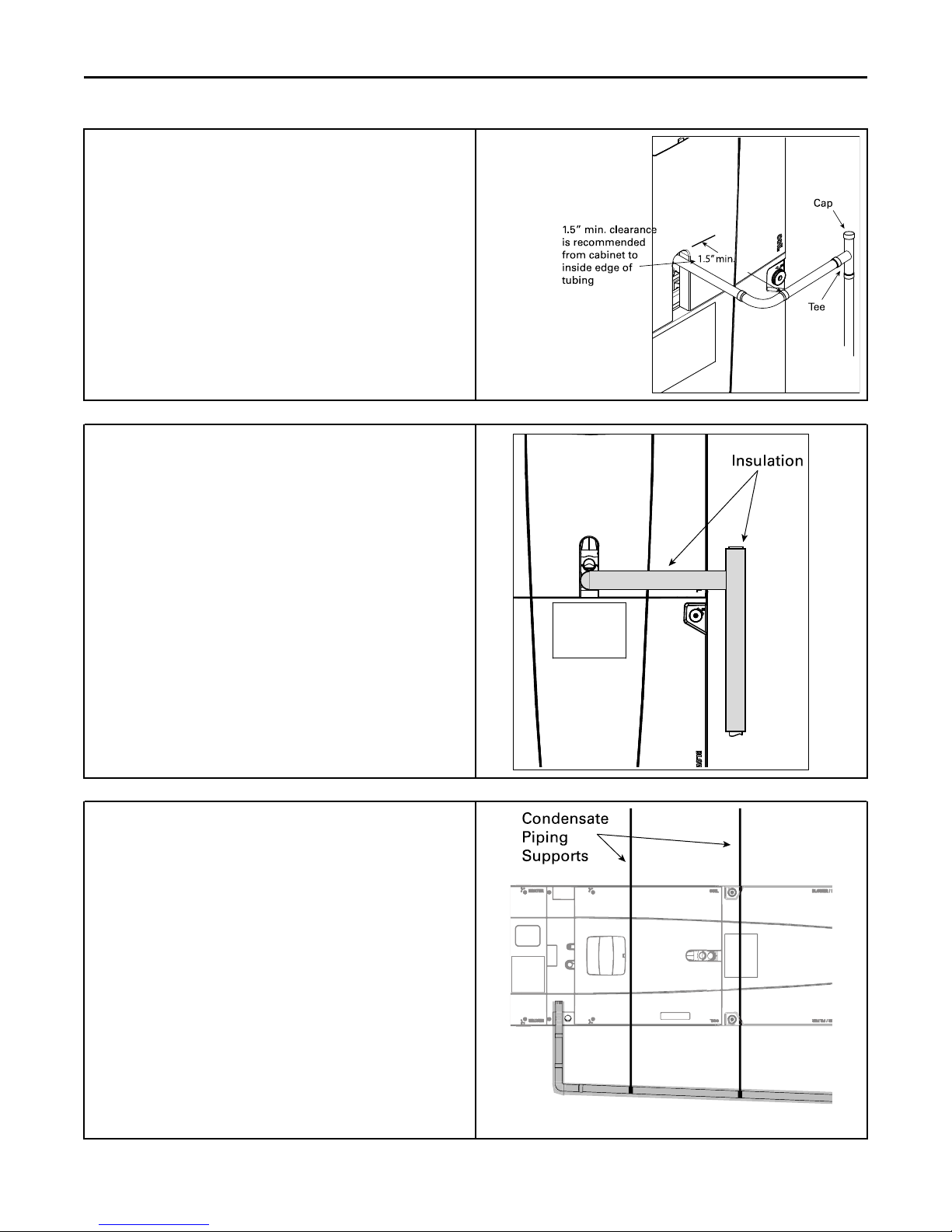
4. Install a clean-out tee in the primary drain line for future
1.5” min.
Cap
Te e
1.5” min. clearance
is recomm e nded
from cabin et to
inside edge of
tubi n g
Insulation
Condensate
Piping
Suppor ts
maintenance. It is recommended that you install a cap on the top
of the tee.
5. Insulate the primary drain line to prevent sweating where dew
point temperatures may be met. (Optional depending on climate
and application needs.)
Provide a means of drainage to prevent winter freeze-up of
condensate line (Optional depending on climate and application
needs).
CCoonnddeennssaattee DDrraaiinn PPiippiinngg
6. Support the condensate piping outside the unit per local codes for
proper drainage and to prevent sagging.
Allow 1/4” of downward slope for each foot of pipe.
18-GJ06D2-2E-EN
31
Page 32
Electrical — Low Voltage
5”
Table 16. Low Voltage Maximum Wire Length
The associated table defines the maximum
total length of low voltage wiring from the
outdoor unit to the indoor unit, and to the
thermostat.
Table 17. Low Voltage Hook-up Instructions
Note: Strain relief must be provided on the inside of the air handler
cabinet for the low voltage wiring. Field supplied thermostat
wired may be wire tied as a bundle to the existing strain
relieved low voltage pigtail leads in the air handler unit.
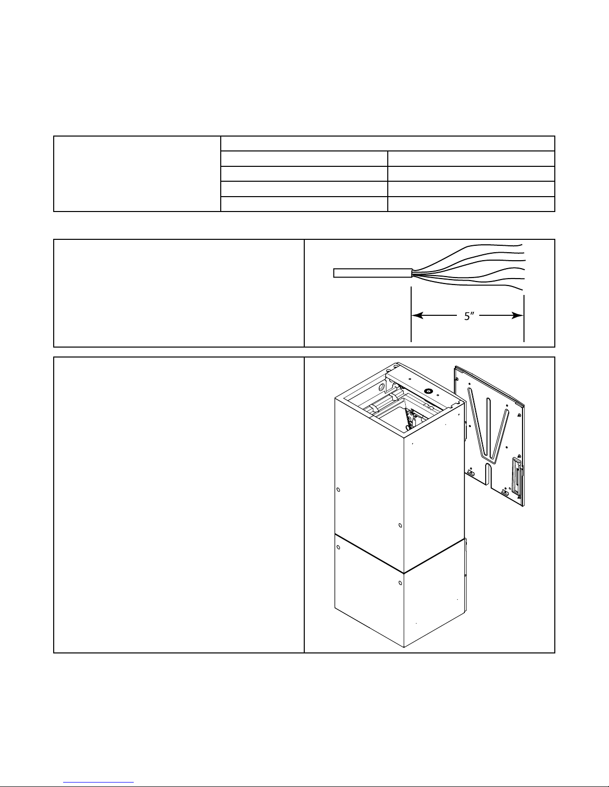
1. Route control wiring to unit. Remove the external sheathing of the
wiring approximately 5”.
Note: Optional Low Voltage Conduit Entry Kit number BAYLVKIT100A
is available.
2. Remove Coil panel by turning the Phillips head door fasteners,
rotating the door away from the cabinet, and removing.
24 VOLTS
WIRE SIZE MAX. WIRE LENGTH
18 AWG 150 FT.
16 AWG 225 FT.
14 AWG 300 FT.
32
18-GJ06D2-2E-EN
Page 33
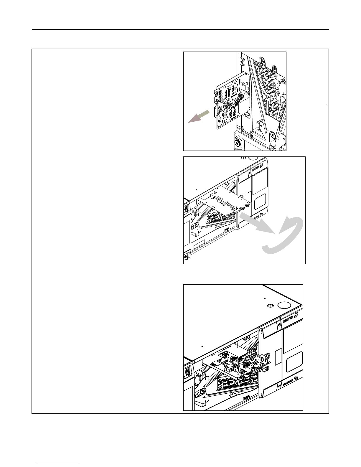
3. Remove the control board from the control pocket by sliding the
control pocket mounting plate out until the first stop is reached.
For Horizontal Right Installations Only
Remove the control board completely from the control pocket. Rotate
the control board 180 degrees. Place the control board 2–3 inches
back into the control pocket. Attach wiring per appropriate hook-up
diagram or perform service.
EElleeccttrriiccaall —— LLooww VVoollttaaggee
Important: After wires have been connected or service performed,
the control board MUST be rotated back to the original
orientation before inserting into cabinet control pocket.
18-GJ06D2-2E-EN
33
Page 34
Scan to see a
video on Field
Wirin g the TAM7
Comfort Control
Air Handler
Air Conditioner
Neatly bundl e all low voltage
wires behin d the service
valve cover as shown.
Field wiring
Yellow
Blue
Red
Yellow
Green
White
Blue
B
B - Blue
W
G
Y1
Y2
Y1 - Yellow
R
O
O
R
B
YI
W1
YO
Y2
BK
G
W2
W3 *
(In)
(Out)
EElleeccttrriiccaall —— LLooww VVoollttaaggee
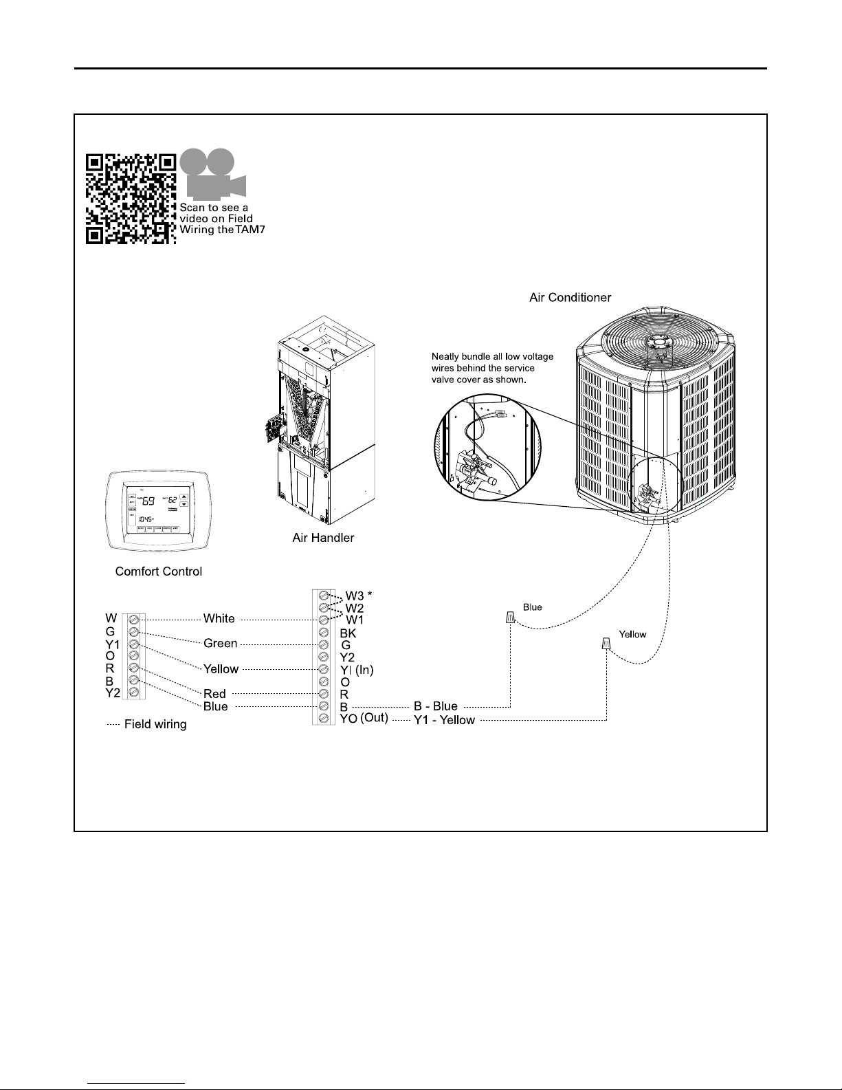
4. Make connections per hookup diagrams.
Figure 1. Field Wiring — Single Stage Cooling
• * For multiple stages of electric heat, jumper W1, W2, and W3 together if control has only one stage of heat.
• Yi and Y0 connections must be made as shown for freeze protection and internally mounted condensate overflow circuits to work properly.
OD unit pump down may occur if these connections are not made correctly.
• Internally mounted condensate switch is optional and must be ordered separately.
• If 3rd party condensate overflow switches are installed, they should be wired between Y of the thermostat and Y1 of the Airflow control.
34
18-GJ06D2-2E-EN
Page 35
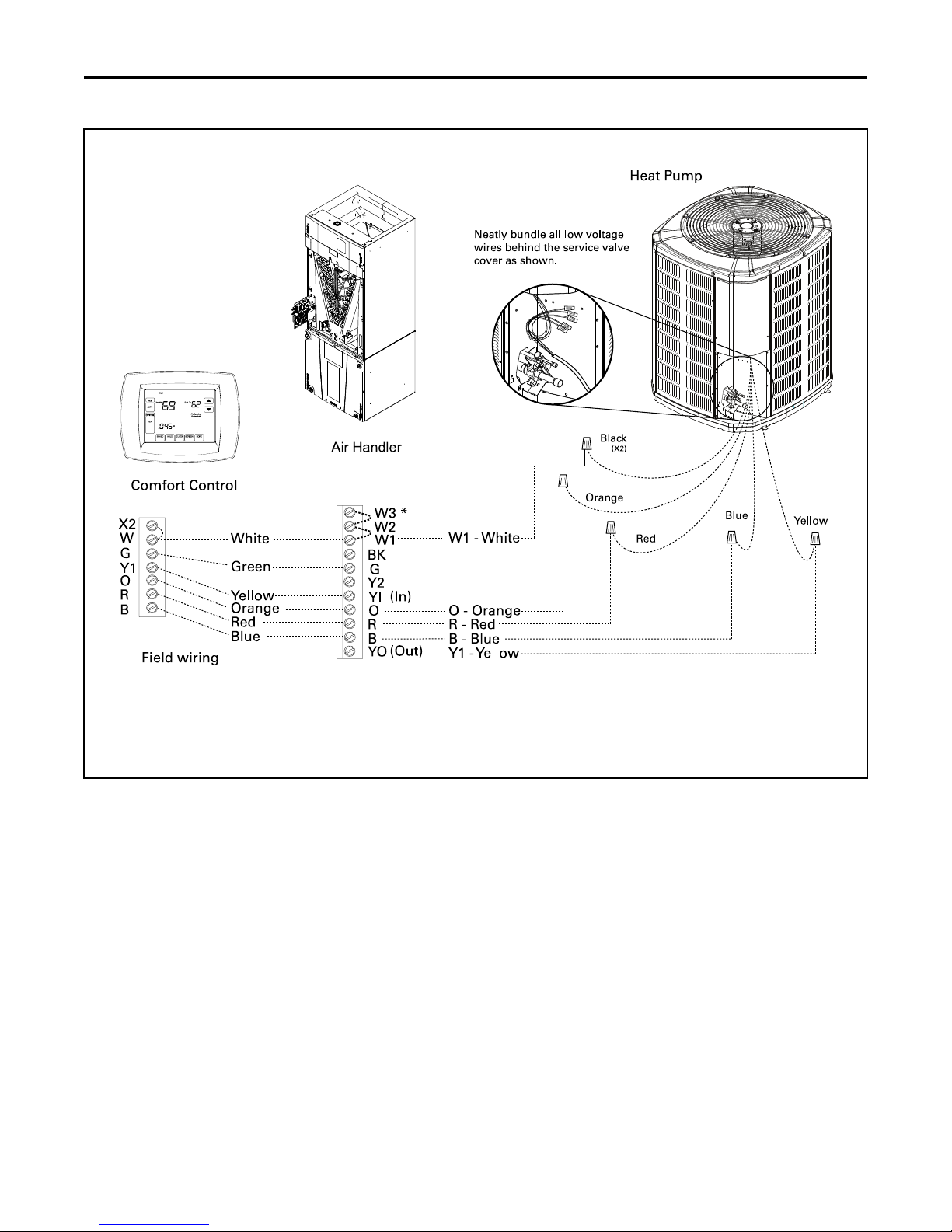
Figure 2. Field Wiring — Single Stage HP
Com for t Control
Air Handler
Heat P ump
Neatly bundle all low vo ltage
wires behind the service valve
cover as shown.
Field wiring
Yellow
Blue
Black
(X2)
Red
Orange
Red
Yellow
Orange
Green
White
Blue
B
B - Blue
W
X2
G
Y1
Y1 - Yellow
R
O
O
R
B
YI
Y2
W1
YO
BK
G
W2
W3 *
R - Red
O - Orange
(In)
(Out)
W1 - White
EElleeccttrriiccaall —— LLooww VVoollttaaggee
• * For multiple stages of electric heat, jumper W1, W2, and W3 together if control has only one stage of heat.
• Yi and Y0 connections must be made as shown for freeze protection and internally mounted condensate overflow circuits to work properly.
OD unit pump down may occur if these connections are not made correctly.
• Internally mounted condensate switch is optional and must be ordered separately.
• If 3rd party condensate overflow switches are installed, they should be wired between Y of the thermostat and Y1 of the Airflow control.
18-GJ06D2-2E-EN
35
Page 36
Com for t Control
Air Handler
Air Conditioner
Neatly bundle all low voltage
wires behind th e service
valve co ver as sho wn.
Yellow/Red
Field wiring
Yellow/Black
Blue
Red
Yellow
Green
White
Blue
B
B - Blue
W
G
Y1
Brown
Y2
Y1 - Yellow
Y2 - Brown
R
O
O
R
B
YI
W1
YO
Y2
BK
G
W2
W3 *
(In)
(Out)
EElleeccttrriiccaall —— LLooww VVoollttaaggee
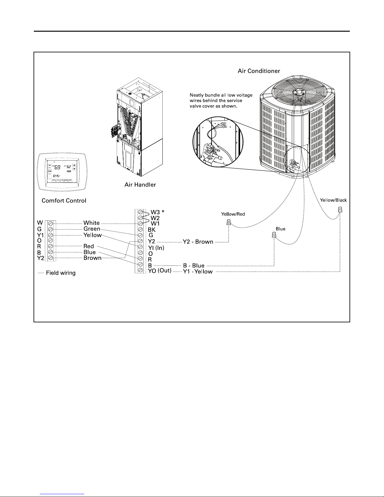
Figure 3. Field Wiring — Two Stage Cooling
• * For multiple stages of electric heat, jumper W1, W2, and W3 together if control has only one stage of heat.
• Yi and Y0 connections must be made as shown for freeze protection and internally mounted condensate overflow circuits to work properly.
OD unit pump down may occur if these connections are not made correctly.
• Internally mounted condensate switch is optional and must be ordered separately.
• If 3rd party condensate overflow switches are installed, they should be wired between Y of the thermostat and Y1 of the Airflow control.
36
18-GJ06D2-2E-EN
Page 37
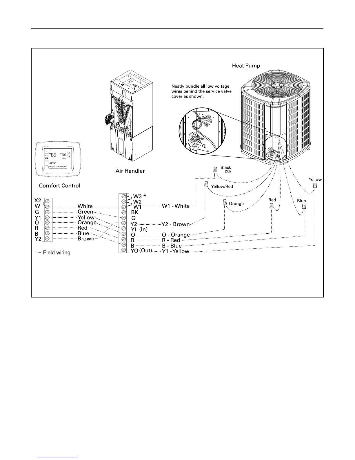
Figure 4. Field Wiring — Two Stage HP
Com for t Control
Air Handler
Heat P um p
Neatly bundle all low voltage
wires behind t h e service va lve
cover as sh own .
Yellow/Red
Field wiring
Yellow
Blue
Black
(X2)
Red
Orange
Red
Yellow
Orange
Green
White
Blue
B
B - Blue
W
X2
G
Y1
Brown
Y2
Y1 - Yellow
Y2 - Brown
R
O
O
R
B
YI
W1
YO
Y2
BK
G
W2
W3 *
R - Red
O - Orange
(In)
(Out)
W1 - White
EElleeccttrriiccaall —— LLooww VVoollttaaggee
• * For multiple stages of electric heat, jumper W1, W2, and W3 together if control has only one stage of heat.
• Yi and Y0 connections must be made as shown for freeze protection and internally mounted condensate overflow circuits to work properly.
OD unit pump down may occur if these connections are not made correctly.
• Internally mounted condensate switch is optional and must be ordered separately.
• If 3rd party condensate overflow switches are installed, they should be wired between Y of the thermostat and Y1 of the Airflow control.
18-GJ06D2-2E-EN
37
Page 38
R71
D21
L4
D24
C18
R90
C12
D7
D4
R85
R74
C28
D23
C
31
D26
R41
R45
R37
X1
Q9
C21
R
91
R87
R28
Q7
Q6
Q5
R49
D3
C42
Q8
R4
R53
R54
C41
R57
C26
C27
D19
D17
C34
C17
C13
C14
R39
R88
C40
C29
R22
C38
C32
C33
D12
R27
R20 C16
R83
D20
R15
R14
L1
C37
R3
D1
R43
D25
R70
D22
R79
R51
R55
R52
R56
R60
D15
R80
R82
C11
R46
R81
L5
R84
R47
R33
R21
R32
D11
U3
R42
R31
R2
R38
D13
R7
C6
C2
U1
R36
R34
R35R6R16
R86
R12
R26
C36
R48
R78
R72
C30
R73
R77
R59
D8
R5
R19
R40
D5
R44
L2
MOV1
J2
U4
R9
C3
L3
R17
R25
J7
D16
R30
C1
R11
C4
R75
C15
R29
R76
J4
D18
D14
R8
MH4
C5
Q4
C35
J1
J6
Q1
Q2
Q3
MH3
R10
MH1
J5
MH2
J3
TEST
CLOSE
VSS
+5V
+V GND
OPEN
2 1
OVR
B/Z
R22
PGD
PG
C
FAULT
UNIT
P/NLABEL
C
L
R
VDD
BARCODE
GAS
TEMP
FLOW
+12V
STATUS
3
GND
TEMP
EVAP
A/Y
R410
TRANE U.S. INC.
J3
OVR
GAS
TEMP
FLOW
+12V
GND
TEMP
EVAP
Pb
FAULT
UNIT
48
33
32
17
16
1
64
49
BK Jumper
TEST
TRANE U.S.INC.
V
DD
PG
D
M
C
L
R
V
S
S
PGC
3.
3
V
SCL
SDA
GND
HUM
5V
MOTOR
GND
RX
TX
+12V
PART NO.LABEL
BARCODE
1 2 3 4 5
1 2 3 4 5
STATUS
Yo Jumper
+12V
+13.8V
C60
C59
R57 R5 8
R64R65
R76R78
C20
C28
C55
S3
R110
R59
R41
R68
C40
R108
R93
R109
R12
R55
R23
R20
R49
R13
R14
D23
D19
D18
C46
C39
C6
C23
R80
J13
R71
R67
R52
R75
R72
Q2
C41
R61
Q6
Q7
R1
R33
R34
J4
Q1
X1
U5
U4
U3
TZ2
T2
T1
R99
R98
R97
R60
R96
R95
R21
R91
R87
R88
R70
R86
R83
R81
R66
R79
R77
R54
R103
R106
R4
R104
R51
R53
R48
R47
R44
R42
R39
R82
R37
R35
R31
R30
R74
R89
R25 R18
R19
R10
R9
R8
R3
R2
R5
R7
Q8
Q4
PTC1
MOV1
L2
L3
K1
J3
J6
J9
D36
D35
D34
D1
D22
D29
D25
D24
D7
D4
D2
D28
C57
C54
C56
C51
C49
C48
C47
C52
C43
C42
C36
C35
C3
4
C31
C30
C29
C13
C7
C3
C2
C1
U1
C58
R105
C50
U2
J7
R24
R17
D6
D3
D14
D17
RNET 1
RNET 2
R73
1
J8
Yo
R
B
O
Y1
J1
W2
W1
R63
R62
R56
D21
D20
C32
C33
R38
R36
R16
R15
R32
R11
R28
R27
R26
D13
D12
D5
D11
D10
C24
C25
C4C5C16C17
D8
R50
R45
R85
R84
D16
D15
D31
D30
C26
C27
C44
C45
D32
D33
R94
R100
R101
R
1
0
7
R29
K2
R6
C53
C22
C19
C
1
5
C
12
C9
C8
C11
C14
C18
C2
1
D26
R69
C37
C38
C10
D9
L1
R102
D27
R40
R22
R46
R43
Q3
Q5
S2 Dip Switch
Distribution Board
S1 Dip Switch
Airflow Control (AFC)
Electronic Expansion Valve Control (EVC)
J7 Jumper
Wire Ties
1
1
HP
2(Compres sor)
2(Stag es)
AC (System)
}
Capacity (Tons)
OUTDOOR
}
Torque
CFM/Ton
Cool OffDelay
}
INDOOR
CFM
S1
on
on
S2
Scan to see a
video on setting
the TAM7 DIP
Switche s.
R71
D21
L4
D24
C18
R90
C12
R74
C28
D23
C31
D26
R41
R45
R37
X1
Q9
C21
R91
R87
R53
R54
C41
R57
C26
C27
D19
D17
C34
C17
C13
C14
R39
R88
C40
D25
R70
D22
R79
R51
R55
R52
R56
R60
D15
R80
R
8
2
C11
R46
R81
L5
R84
R47
R33
R21
R32
D11
U3
R42
R31
C6
R86
U4
R17
R25
J7
D16
R30
R11
R75
C15
R29
R76
J4
D18
D14
R8
MH4
C5
C35
R10
MH1
J5
TEST
CLOSE
VSS
OPEN
2 1
R22
PGD
PGC
FAULT
UNIT
P/N LABEL
C
L
R
VDD
BARCODE
STATUS
3
R410
TRANEU.S.INC.
J7 Jumper
Electronic Expansion Valve Control (EVC)
EElleeccttrriiccaall —— LLooww VVoollttaaggee
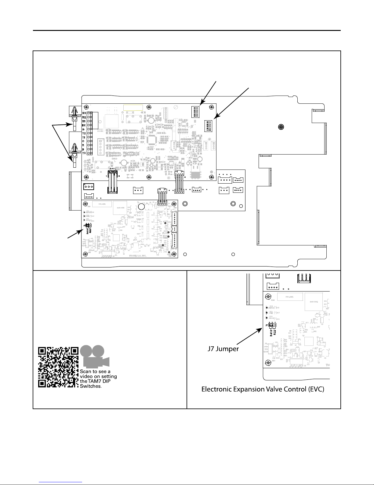
5. Secure the sheathed wiring to the control pocket mounting plate using the factory supplied wire ties attached to the tabs as shown.
6. Set Jumper and Dip Switches
• Set the system refrigerant to either R410A or R-22 using the
Refrigerant Jumper located on the Expansion Valve Control board
(EVC) in the Control Pocket.
• Factory default is R410A.
Note: The power must be shut off and then re-applied in order for the
EVC to recognize the change.
38
18-GJ06D2-2E-EN
Page 39
Dip Switches
Scan to see a
video on setting
the TAM7 DIP
Switche s.
1
1
1 2 3 4 5
1 2 3 4 5
HP
2 (Compressor)
2 (S tages )
AC (Sys tem)
}
OUTDOOR
Ca pacity (Tons )
OUTDOOR
}
Torque
CFM/Ton
Co ol Off Delay
}
INDOOR
CFM
+12V
R13
R14
R4
U1
R NET 1
S1
on
on
S2
R NET 2
R
6
C22
C19
C10
D9
1
Airflow Control (AFC)
S1
Click or Scan to see a video on setting the
TAM7 DIP Switches
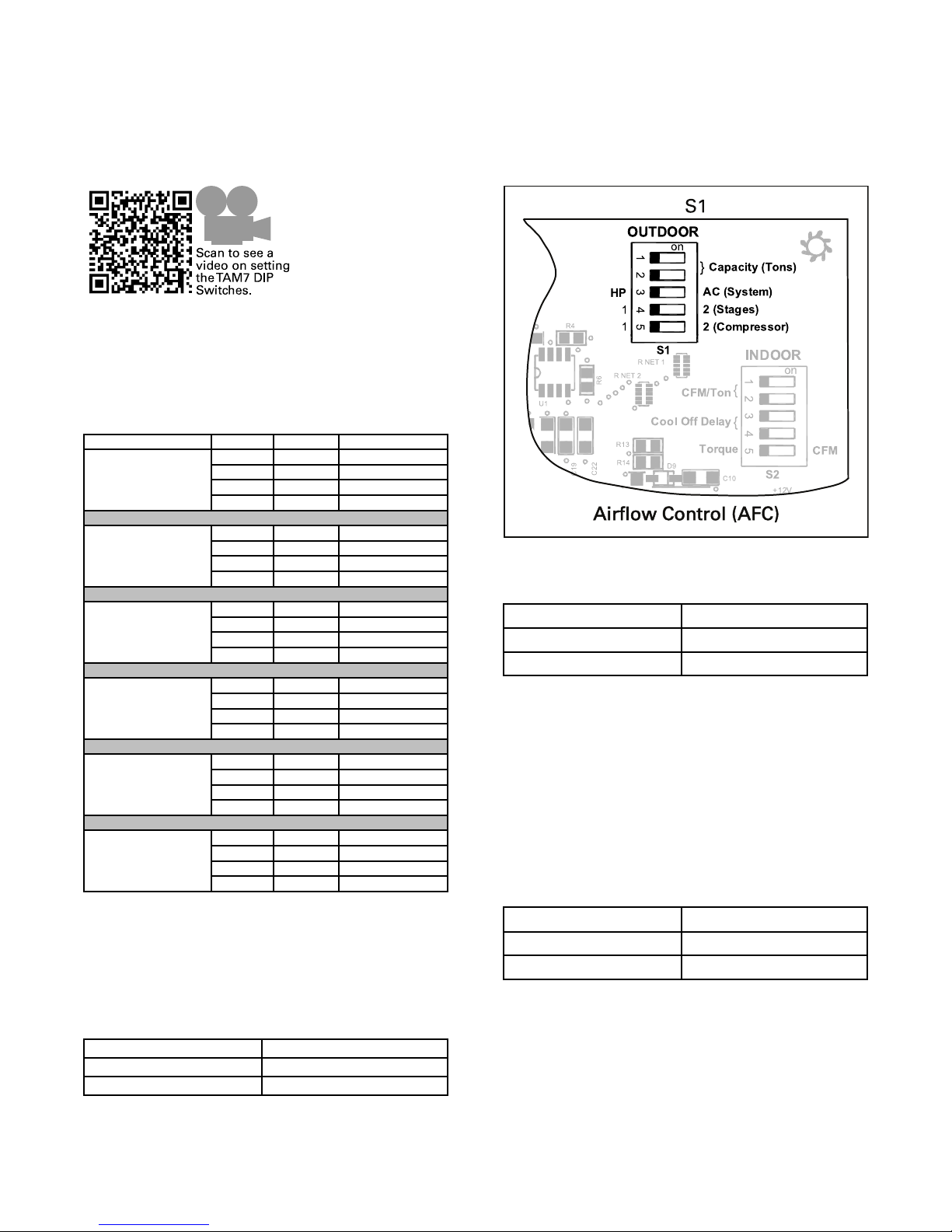
DDiipp SSwwiittcchh SS11
• Set the S1–1 and S1–2 dip switches for the OD
multiplier (tonnage) per the chart.
INDOOR MODEL S1–1 S1–2 OD MULTIPLIER
TAM7A0A24H21SD
TAM7A0A24H21EA
TAM7A0B30H21SD
TAM7A0B30H21EA
OFF OFF 2
OFF ON 1.5
ON OFF 2.5
ON ON 3
OFF OFF 2
OFF ON 1.5
ON OFF 2.5
ON ON 3
• Set the S1–4 dip switch for the number of stages on
the outdoor unit.
OFF OFF 3
TAM7A0C36H31SD
TAM7A0C36H31EA
TAM7A0C42H31SD
TAM7A0C42H31EA
TAM7A0C48H41SD
TAM7A0C48H41EA
TAM7B0C60H51SC
TAM7B0C60H51EA
OFF ON 2
ON OFF 2.5
ON ON 3.5
OFF OFF 3.5
OFF ON 2.5
ON OFF 3
ON ON 4
OFF OFF 4
OFF ON 3
ON OFF 3.5
ON ON 4.5**
OFF OFF 4.5**
OFF ON 3.5
ON OFF 4
ON ON 5
NNoottee:: The OD multiplier in conjunction with the CFM/
TON can be used to adjust total airflow for your
application.
Example: 4.5T x 370 CFM/TON = 1665 CFM
** Not an actual OD size
• Set the S1–3 dip switch for AC or HP.
OD TYPE S1–3
18-GJ06D2-2E-EN
HP OFF
AC ON
OD STAGES S1–4
1 OFF
2 ON
NNoottee:: Refer to the field wiring diagram of the Outdoor
Unit to determine if the unit is 1 or 2 stage.
NNoottee:: This dip switch should be changed while the
power is off or no demand is present. The power
must be shut off and then re-applied in order for
the AFC to recognize the change.
• Set the S1–5 dip switch for the number of
compressors.
# COMPRESSORS S1–5
1 OFF
2 ON
39
Page 40
1
1
1 2 3 4 5
1 2 3 4 5
HP
2 (Compres s or)
2 (Stage s )
AC (Sys tem)
}
OUTDOOR
Ca pac ity (Tons)
OUTDOOR
}
Torqu e
CFM/Ton
Co ol Off Delay
}
INDOOR
CFM
+12V
R13
R14
R4
U1
R NET 1
S1
on
on
S2
R NET 2
R
6
C22
C19
C
1
5
C
1
2
8
C10
D9
L
1
S 2
Airflow Control (AFC)
OFF OFF
50%
80%
100% if necessary
50%
Dehumidify
Fast Coil Cooling
Efficiency
7.5
minutes
3
minutes
1
minute
FAN OPERATION (CFM)
OFF
CCOMPRESSO R OPERATION
as required
DDiipp SSwwiittcchheess
DDiipp SSwwiittcchh SS22
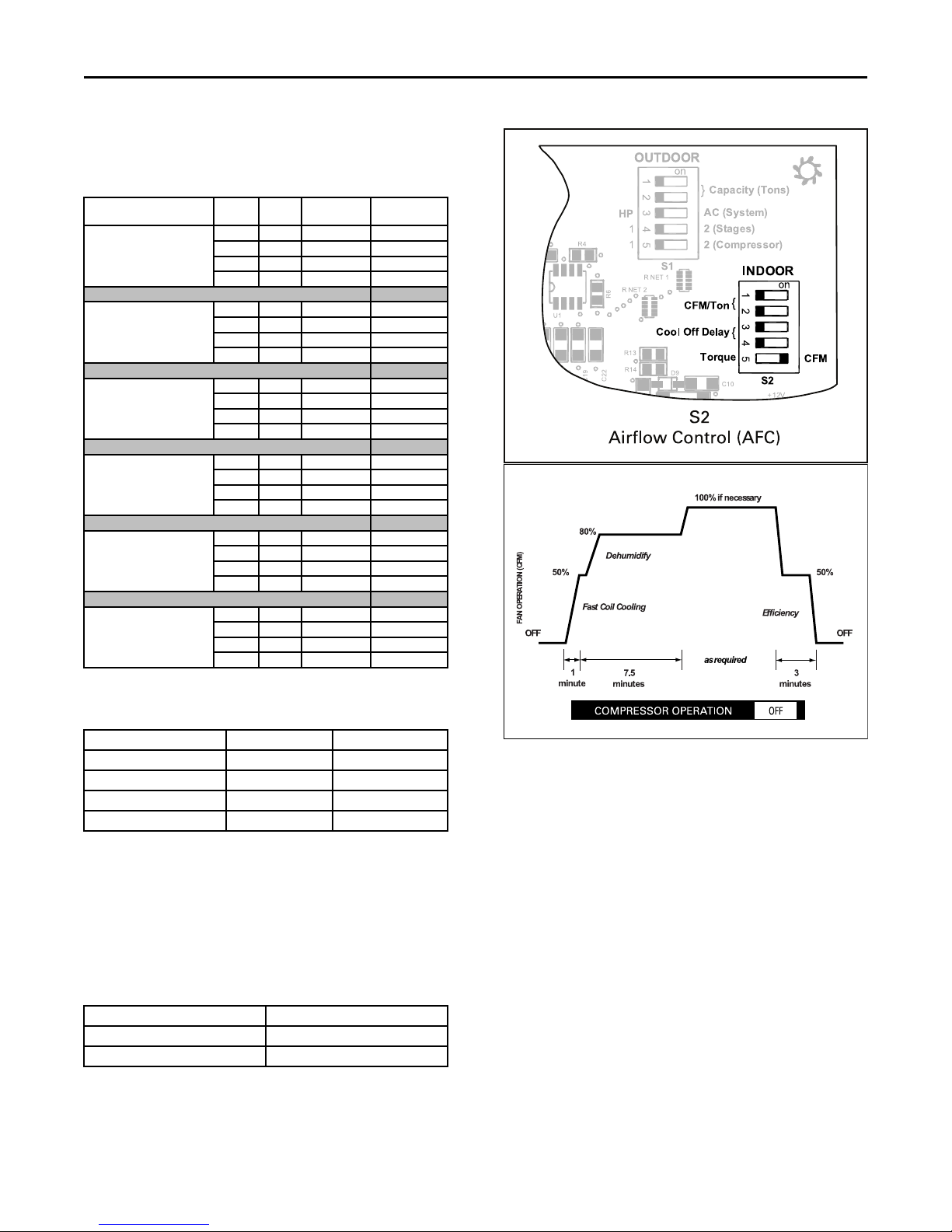
• Set the S2–1 and S2–2 dip switches for the Cooling
and Heating CFM/Ton.
INDOOR MODEL S2–1 S2–2
OFF OFF 400 430
TAM7A0A24H21SD
TAM7A0A24H21EA
TAM7A0B30H21SD
TAM7A0B30H21EA
TAM7A0C36H31SD
TAM7A0C36H31EA
TAM7A0C42H31SD
TAM7A0C42H31EA
OFF ON 360 390
ON OFF 380 410
ON ON 420 450
OFF OFF 400 430
OFF ON 360 390
ON OFF 380 410
ON ON 420 450
OFF OFF 370 420
OFF ON 350 400
ON OFF 390 440
ON ON 410 450
OFF OFF 370 400
OFF ON 330 360
ON OFF 350 380
ON ON 390 420
COOLING
CFM/TON
HEATING
CFM/TON
OFF OFF 350 400
TAM7A0C48H41SD
TAM7A0C48H41EA
TAM7B0C60H51SC
TAM7B0C60H51EA
OFF ON 330 380
ON OFF 370 420
ON ON 390 440
OFF OFF 370 400
OFF ON 380 410
ON OFF 390 420
ON ON 400 430
• Set the S2–3 and S2–4 dip switches for the Blower
Off and Delay.
BLOWER OFF DELAY S2–3 S2–4
1.5M @ 100%
NO DELAY OFF ON
3M @ 50%
ENHANCED ON ON
OFF OFF
ON OFF
IInnddoooorr BBlloowweerr TTiimmiinngg
This ENHANCED MODE selection provides a ramping
up and ramping down of the blower speed to provide
improved comfort, quietness, and potential energy
savings. The graph on the right shows the ramping
process. Enhanced Mode works in cooling, HP, heating,
Torque, and constant CFM modes.
• Set the S2–5 dip switch for the airflow mode.
AIRFLOW MODE S2–5
CONSTANT CFM ON
40
*TORQUE
OFF
• All zoning applications MUST be set to Constant
CFM mode.
• Torque mode is optional and is recommended for
high static applications. High static conditions
dramatically increase energy consumption with
variable speed motors. Evaluate the blower
performance table in relationship to the duct
system to determine the benefit of each installation.
• For the 2 ton air handler, torque mode will reduce
airflow when static is above approximately 0.3”
water column.
• For the 2–1/2, 3, and 3–1/2 ton air handlers, torque
mode will reduce airflow when static is above
approximately 0.35" water column.
• For the 4 and 5 ton air handlers, torque mode will
reduce airflow when static is above approximately
0.4” water column.
When selected, Torque Mode is used for cooling
operation only.
All heating modes default to constant CFM.
18-GJ06D2-2E-EN
Page 41
Indoor Blower Options
FAULT
UNIT
48
33
32
17
16
1
64
49
BK Jump er
TEST
TRANE U.S. INC.
V
DD
PG
D
M
C
L
R
V
S
S
PGC
3.
3
V
SCL
SDA
GND
HUM
PART NO. LABEL
BARCODE
STATUS
Yo Jumper
+13.8V
C59
R57 R58
R64R65
R76R78
S3
R110
R41
R68
C40
R93
R109
R12
R55
R23
R20
R49
D23
D19
D18
C46
C39
C6
C23
R80
R71
R67
R52
R75
R72
C41
R1
R33
R34
J4
Q1
X1
U4
U3
TZ2
T2
T1
R98
R97
R60
R21
R91
R8
7
R88
R70
R86
R66
R79
R77
R54
R106
R104
R42
R39
R82
R74
R25 R18
R19
R10
R9
R8
R3
R2
R5
R7
Q8
MOV1
L2
L3
K1
J6
J9
D36
D35
D1
D22
D29
D25
D24
D7
D4
D2
D28
C51
C49
C48
C47
C52
C43
C36
C35
C3
4
C31
C30
C29
C7
C3
C2
C1
C58
C50
U2
R24
R17
D6
D3
R73
1
J8
Yo
R
B
O
Y1
J1
W2
W1
R63
R62
R56
D21
D20
C32
C33
R38
R36
R16
R15
R32
R11
R28
R27
R26
D13
D12
D5
D11
D10
C24
C25
C4C5C16C 17
D8
R50
R45
R85
R84
D16
D15
D31
D30
C26
C27
C44
C45
D32
D33
R94
R100
R101
R
1
0
7
K2
C53
C8
D26
R69
C37
C38
R102
D27
R40
R46
R43
BK Jumper
YO Jum per
(
Do Not Cut
)
Airflow Control (AFC)
Comfort Control
Air Handler
Field wiring
Red
Yellow
Green
White
Blue
B
W
G
Y1
Y2
R
O
O
R
B
YI
W1
YO
Y2
BK
G
W2
W3
(In)
(Out)
Humidistat
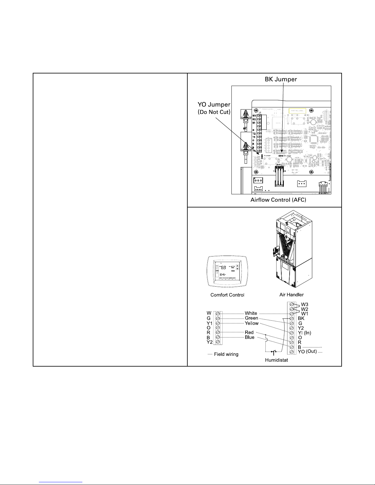
• Humidity Control for Cooling — This unit is capable of providing
additional dehumidification during the cooling mode by reducing
the airflow when humidity is above the set point. A conventional
field supplied humidistat is required to control this function.
1. Cut the BK jumper on the AFC.
2. Using a field supplied humidistat, wire 24VAC Hot to one side of
the humidistat. Wire the other side of the humidistat to the BK
terminal on the low voltage terminal board. See wiring diagram.
• Pulse Width Modulation (PWM) — Typically used with A/
TCONT402 or zoning control.
1. The BK jumper must be cut on the AFC.
— Do Not cut the Y0 jumper.
• All zoning applications MUST be set to Constant CFM mode.
18-GJ06D2-2E-EN
41
Page 42
Control Plate Reinstall
P
ass through notch
in coil acce ss door
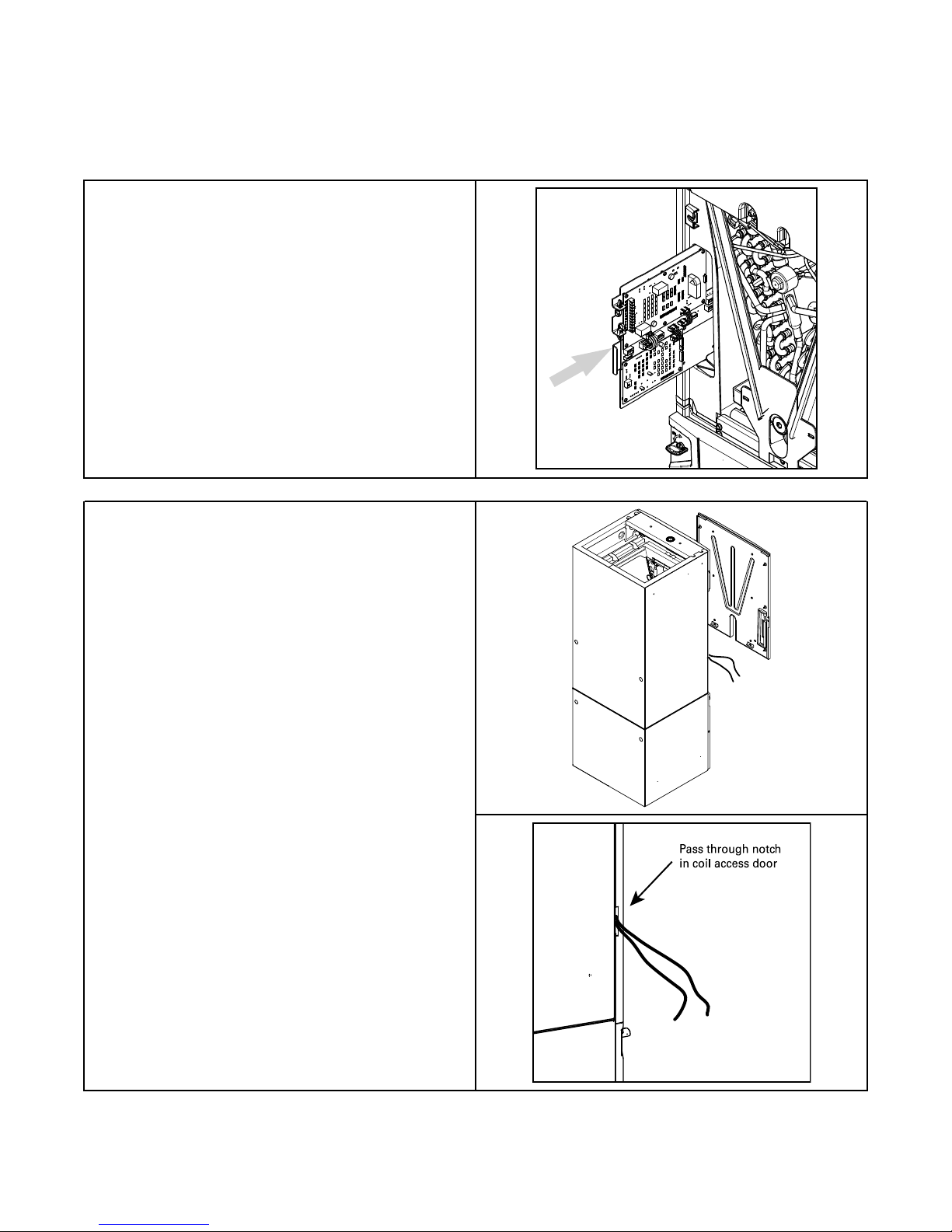
1. Slide control plate assembly into the control pocket until fully
seated. The control plate should be flush with the outer edge of
the unit.
2. Replace coil panel making sure that the wires are located within
the wire pass-through provided in the panel.
42
18-GJ06D2-2E-EN
Page 43
Electrical — High Voltage
Conduit Entry P oints
Table 18. High Voltage Power Supply
The high voltage power supply must match the equipment nameplate.
Power wiring, including ground wiring must comply with national,
sate, and local codes.
Field wiring diagrams for supplementary electric heaters are shipped
with the heaters.
Table 19. Make Electrical Connections
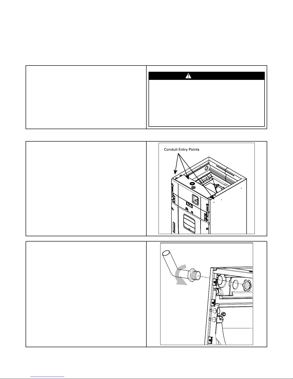
1. Route High Voltage wiring to unit.
2. Select a conduit entry point. Drill a hole for the desired conduit
size on units without a plug. A locating target is identified on these
units.
a. Select the entry point you will use to bring in your high
voltage wiring.
b. Remove plug from the entry point.
WWAARRNNIINNGG
LLIIVVEE EELLEECCTTRRIICCAALL CCOOMMPPOONNEENNTTSS!!
FFaaiilluurree ttoo ffoollllooww tthhiiss WWaarrnniinngg ccoouulldd rreessuulltt iinn
pprrooppeerrttyy ddaammaaggee,, sseevveerree ppeerrssoonnaall iinnjjuurryy,, oorr ddeeaatthh..
FFoollllooww aallll eelleeccttrriiccaall ssaaffeettyy pprreeccaauuttiioonnss wwhheenn
eexxppoosseedd ttoo lliivvee eelleeccttrriiccaall ccoommppoonneennttss.. IItt mmaayy bbee
nneecceessssaarryy ttoo wwoorrkk wwiitthh lliivvee eelleeccttrriiccaall ccoommppoonneennttss
dduurriinngg iinnssttaallllaattiioonn,, tteessttiinngg,, sseerrvviicciinngg,, aanndd
ttrroouubblleesshhoooottiinngg ooff tthhiiss pprroodduucctt..
3. Route conduit (if used) to the entry point and connect.
a. Use one hand to secure the conduit nut from inside of the
heater compartment.
b. Connect a field supplied 3/4” or 1–1/2” conduit to conduit
nut.
Note: Reducing bushings may be required for your application.
18-GJ06D2-2E-EN
43
Page 44
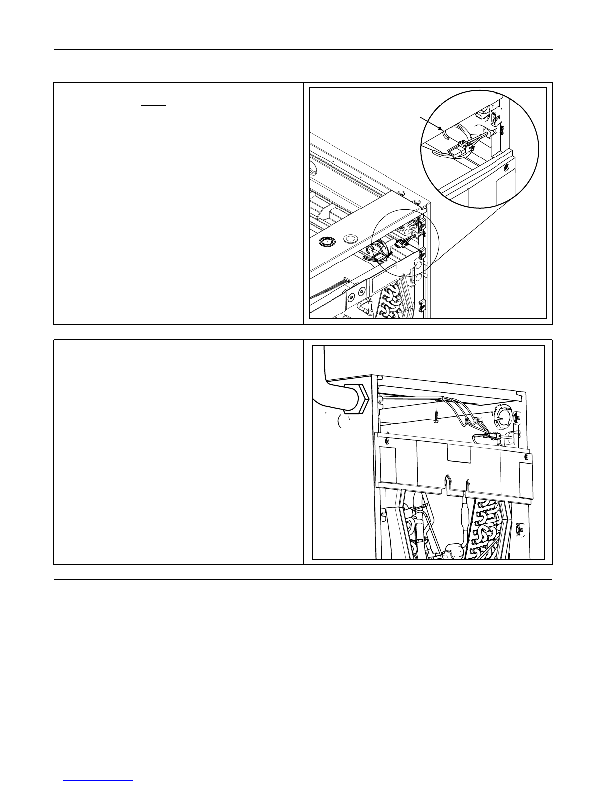
BLACK
RED
GREEN - GROUND
EElleeccttrriiccaall —— HHiigghh VVoollttaaggee
4. If an electric heater IS NOT being installed, remove the pigtail
harness from the documentation pack and connect it to the plug
on the inside of the Heater Compartment in the cabinet.
If an electric heater IS being installed, see the Installer’s Guide
shipped with the electric heater.
Connect L1, L2, and ground wiring to pigtail harness in Heater
Compartment using wire nuts. The incoming ground wiring will mate
up with the green wire shown in the illustration.
5. If the L1, L2, and ground wires enter the case from the left side,
use a field supplied 1/2” — 5/8” maximum length screw and wire
tie to hold the wires to the top center of the Heater Compartment.
44
18-GJ06D2-2E-EN
Page 45
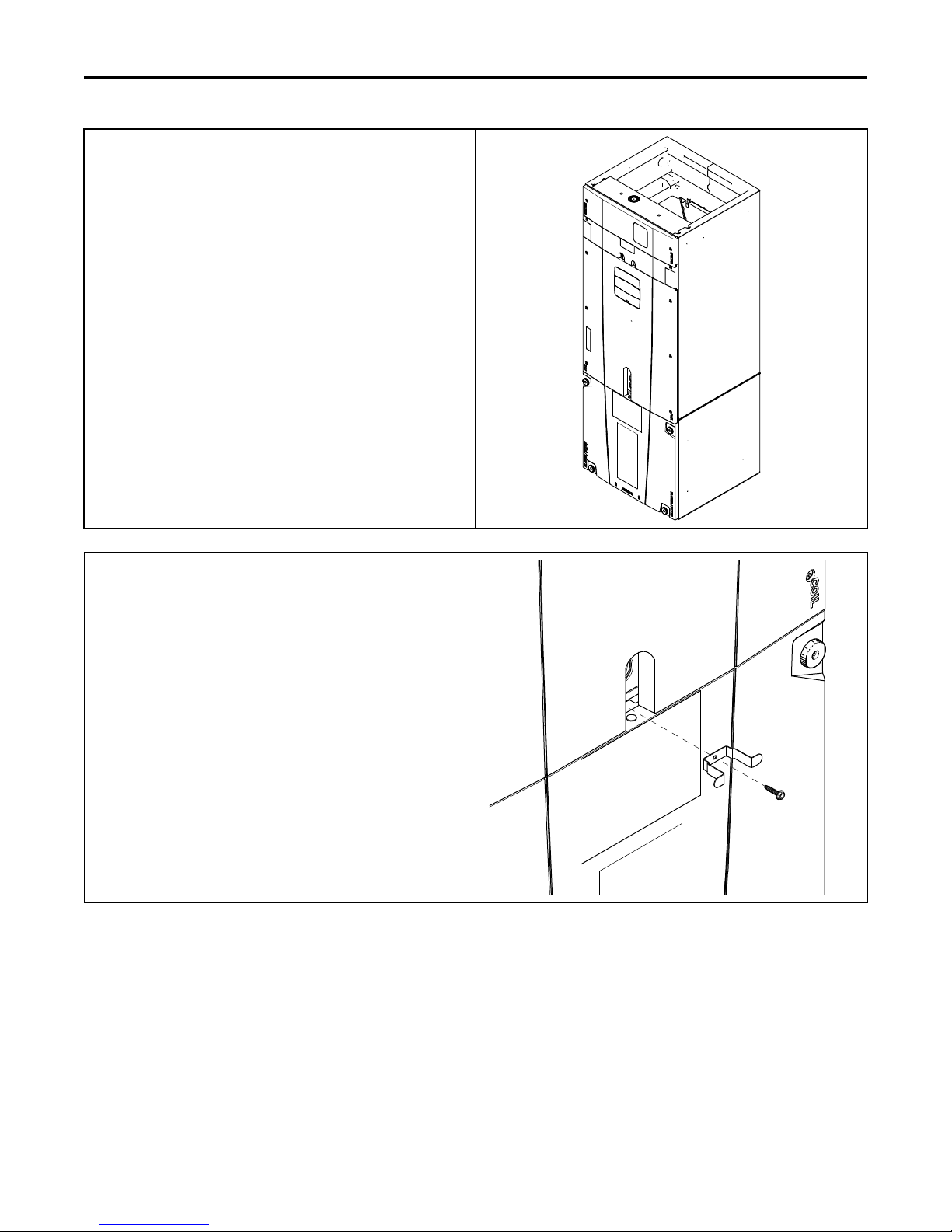
6. Reinstall all panels before starting the air handler
Note: After replacing all panels, loosen the Line Set Panel screws
approximately 1/4 — 1/2 turn. This will improve the seal
between the Heater Panel and Line Set Panel.
EElleeccttrriiccaall —— HHiigghh VVoollttaaggee
7. Remove screw and coil bracket from documentation packet.
8. Place the coil panel bracket into position and use screw to secure
the coil panel bracket and seal plate to the support bar.
Important: The Coil Seal Plate and screw secure the coil in the center
Important: The Blower Panel may be removed if needed to help align
Important: For the 5 ton air handler model, tap 5 should not be used
of the air handler. Failure to follow these steps can
prevent the Coil Panel from being easily replaced on the
unit.
the new screw with the seal plate and crossmember.
in the downflow or horizontal orientations. Using Tap 5
could result in water blowing off the coil.
18-GJ06D2-2E-EN
45
Page 46
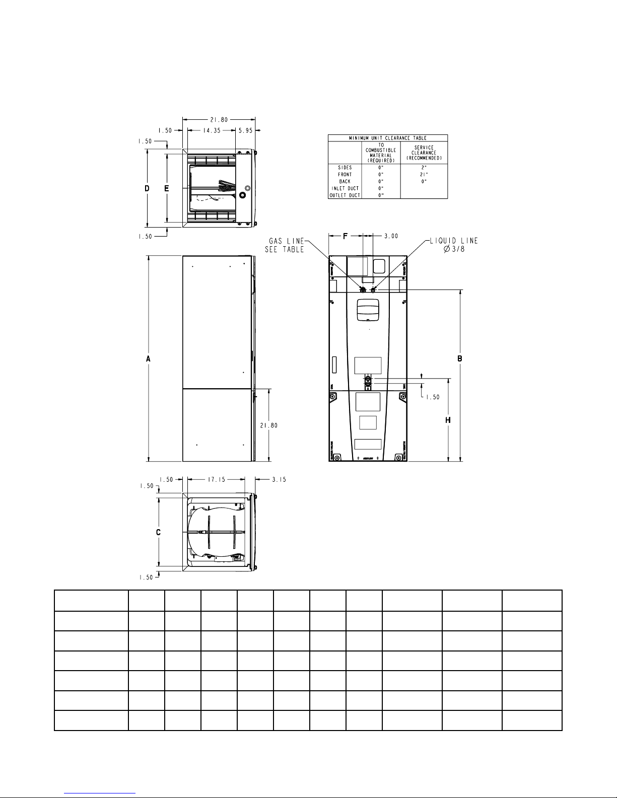
TAM7 OUTLINE DRAWING
Model Number A B C D E F H
TAM7A0A24H21SD
TAM7A0A24H21EA
TAM7A0B30H21SD
TAM7A0B30H21EA
TAM7A0C36H31SD
TAM7A0C36H31EA
TAM7A0C42H31SD
TAM7A0C42H31EA
TAM7A0C48H41SD
TAM7A0C48H41EA
TAM7B0C60H51SC
TAM7B0C60H51EA
46
49.9 39.6 14.5 17.5 14.5 7.3 24.4 EEV
55.7 45.5 18.4 21.3 18.4 9.2 24.8 EEV
56.9 46.7 20.5 23.5 20.5 10.3 24.2 EEV
56.9 46.7 20.5 23.5 20.5 10.3 24.5 EEV
61.7 51.5 20.5 23.5 20.5 10.3 24.9 EEV
61.7 51.5 20.5 23.5 20.5 10.3 24.9 EEV
FLOW
CONTROL
GAS LINE
BRAZE
3/4 3/8
3/4 3/8
7/8 3/8
7/8 3/8
7/8 3/8
7/8 3/8
18-GJ06D2-2E-EN
LIQ LINE
BRAZE
Page 47
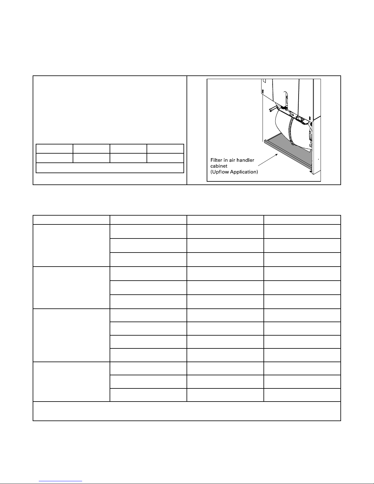
Filters
Filter in a ir ha ndler
cabi net
(Upflow Application)
Table 20. Filter Considerations
• A filter must be installed within the system.
• A filter channel is provided in the unit at the bottom of the Blower/
Filter compartment.
• For customer ease of filter maintenance, it is recommended that a
properly sized remote filter grill(s) be installed for units that are
difficult to access. Airflow should not exceed the maximum rated
velocity of the filter being used.
Table 21. Filter Sizes
Cabinet Size * A B C
Filter Size 16 x 20 20 x 20 22 x 20
* Cabinet size is indicated by the 7th digit in model number.
System Charge Adjustments
System Matched with:
Single Compressor
2–Stage HP
Single Compressor
2–Stage AC
Two Compressor
2–Stage HP
Two Compressor
2–Stage HP
NOTES:
1. Variable Speed outdoor units must be charged per the outdoor unit instructions.
2. All other matches must be charged per the nameplate charging instructions.
Indoor Unit Model No. Outdoor Unit Model No.
TAM7A0B30H21SD
TAM7A0B30H21EA
TAM7A0C36H31SD
TAM7A0C36H31EA
TAM7A0C48H41SD
TAM7A0C48H41EA
TAM7A0B30H21SD
TAM7A0B30H21EA
TAM7A0C36H31SD
TAM7A0C36H31EA
TAM7A0C48H41SD
TAM7A0C48H41EA
TAM7A0B30H21SD
TAM7A0B30H21EA
TAM7A0C36H31SD
TAM7A0C36H31EA
TAM7A0C48H41SD
TAM7A0C48H41EA
TAM7B0C60H51SD
TAM7B0C60H51EA
TAM7A0B30H21SD
TAM7A0B30H21EA
TAM7A0C36H31SD
TAM7A0C36H31EA
TAM7A0C48H41SD
TAM7A0C48H41EA
4A6H6024E/G, 4TWX6024E/G
4A6H7024, 4TWX8024
4A6H6036E/G, 4TWX6036E/G
4A6H7036, 4TWX8036
4A6H6048E/G, 4TWX6048E/G
4A6H7048, 4TWX8048
4A7A6024E/G, 4TTX6024E/G
4A7A7024, 4TTX8024
4A7A6036E/G, 4TTX6036E/G
4A7A7036, 4TTX8036
4A7A6048E/G, 4TTX6048E/G
4A7A7048, 4TTX8048
4TWZ0024A, 4A6Z0024A 9°
4TWZ0036A/B, 4A6Z0036A/B 10°
4TWZ0048A/B, 4A6Z0048A/B 12°
4TWZ0060A, 4A6Z0060A 12°
4TTZ0036A/B, 4A7Z0024A 9°
4ATTZ0036A/B, 4A7Z0036A/B 11°
4TTZ0048A/B, 4A7Z0048A/B 13°
Subcooling
9°
10°
8°
8°
8°
8°
18-GJ06D2-2E-EN
47
Page 48
System Start Up
OFF
DONE
CANCEL
ON
OFF
ON
DONE
CANCEL
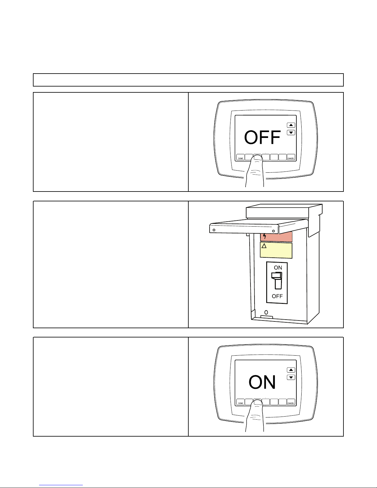
1. Make sure all panels are securely in place and that all wiring has been properly dressed and secured.
2. Set the system thermostat to OFF.
3. Turn on electrical power disconnect(s) to apply power to the
indoor and outdoor units.
4. Set the system thermostat to ON.
48
18-GJ06D2-2E-EN
Page 49

TAM7 Sequence of Operation
Abbreviations
• AFC = Airflow Control
• EVC = Expansion Valve Control
• EEV = Electronic Expansion Valve
• EHC = Electric Heat Control
• HHC= Hydronic Heat Control
• Y1 = Y Signal from the comfort control
• YO = Y Signal out of the AFC from the comfort
control
• Y2 = Y2 Signal from comfort control
This unit has a unique feature that receives 24VAC
analog inputs from a conventional comfort control and
then converts these inputs to serial communicating
signals between the different controls within the air
handler.
The installing and servicing technician should have an
understanding of the sequence of operation to be able
to properly setup and diagnose functions of the air
handler.
The dip switch settings on the control boards must be
properly set to obtain the correct sequence of
operation. Reference the air handler and electric heat
wiring diagrams and dip switch configuration chart for
additional information.
SSeeee uunniitt,, eelleeccttrriicc hheeaatt,, aanndd ffiieelldd wwiirriinngg ddiiaaggrraammss ffoorr
aaddddiittiioonnaall iinnffoorrmmaattiioonn..
CCoonnttiinnuuoouuss FFaann
IImmppoorrttaanntt:: If the indoor air exceeds 60% relative
humidity or simply feels uncomfortably
humid, it is recommended that the indoor
fan only be used in the AUTO mode.
1. R-G contacts close on comfort control sending
24VAC to the G terminal of the AFC.
2. The AFC micro-processor sends a command to the
serial communicating blower motor to run at 50%.
See airflow Dip Switch settings for additional info.
HHeeaatt ppuummpp OODD SSiinnggllee SSttaaggee ((hheeaattiinngg mmooddee))
1. R-Y contacts close on the comfort control sending
24VAC to Y1 terminal on the AFC.
2. Normally closed contacts on the AFC will pass
24VAC to the YO terminal providing power to the
outdoor unit control circuit.
3. R-G contacts close on comfort control sending
24VAC to the G terminal of the AFC.
4. The AFC micro-processor sends a command to the
serial communicating blower motor to run at 100%.
5. The HUM contacts close.
HHeeaatt ppuummpp OODD TTwwoo SSttaaggee ((hheeaattiinngg mmooddee))
1. R-Y contacts close on the comfort control sending
24VAC to Y1 terminal on the AFC.
2. Normally closed contacts on the AFC will pass
24VAC to the YO terminal providing power to the
outdoor unit 1st stage control circuit.
3. R-G contacts close on comfort control sending
24VAC to the G terminal of the AFC.
4. The AFC micro-processor sends a command to the
serial communicating blower motor to run at 1st
stage heating cfm.
5. The HUM contacts close.
6. R-Y2 contacts close on the comfort control sending
24VAC to Y2 terminal on the AFC.
7. The Y2 signal is also passed through to provide
power to the outdoor unit 2nd stage control circuit.
8. The blower motor will now run at 100% of the
heating cfm.
OODD SSiinnggllee SSttaaggee ((ccoooolliinngg mmooddee))
1. R-Y contacts close on the comfort control sending
24VAC to Y1 terminal on the AFC.
2. Normally closed contacts on the AFC will pass
24VAC to the YO terminal providing power to the
outdoor unit control circuit.
a. Heat pump OD > R-O contacts close on the
comfort control sending 24VAC to the O
terminal of the AFC. The AFC communicates to
the EVC that the system is in cooling mode. The
O signal is passed through to the OD unit.
b. Non heat pump OD > OD dip switch
configuration will communicate to the EVC to
control superheat on a Y only signal.
3. R-G contacts close on comfort control sending
24VAC to the G terminal of the AFC.
4. The AFC micro-processor sends a command to the
serial communicating blower motor to run at 100%
of the cooling cfm.
5. The EVC will receive input from the two
temperature sensors and start to control superheat.
18-GJ06D2-2E-EN
49
Page 50

TTAAMM77 SSeeqquueennccee ooff OOppeerraattiioonn
OODD TTwwoo SSttaaggee ((ccoooolliinngg mmooddee))
1. R-Y1 contacts close on the comfort control sending
24VAC to Y1 terminal on the AFC. The AFC
communicates to the EVC to control superheat for
1st stage.
2. Normally closed contacts on the AFC will pass
24VAC to the YO terminal providing power to the
outdoor unit 1st stage control circuit.
a. HHeeaatt ppuummpp OD > R-O contacts close on the
comfort control sending 24VAC to the O
terminal of the AFC. The AFC communicates to
the EVC that the system is in cooling mode. The
O signal is passed through to the OD unit.
b. NNoonn--HHeeaatt ppuummpp OD > OD dip switch
configuration will communicate to the EVC to
control superheat on a Y only signal.
3. R-G contacts close on comfort control sending
24VAC to the G terminal of the AFC.
4. The AFC micro-processor sends a command to the
serial communicating blower motor to run at the 1st
stage cooling cfm. (1st stage cooling cfm is a
multiplier of 2nd stage cfm)
5. The EVC will receive input from the two
temperature sensors and start to control 1st stage
superheat.
6. R-Y2 contacts close on the comfort control sending
24VAC to Y2 terminal on the AFC. The AFC
communicates to the EVC to control superheat for
2nd stage.
7. The Y2 signal is passed through to provide power
to the outdoor unit 2nd stage control circuit.
8. The blower motor will now run at 100% of the
cooling cfm.
EElleeccttrriicc HHeeaatt
1. R-W contacts close on the comfort control sending
24VAC to W1 of the AFC.
2. R-G contacts close on the comfort control sending
24VAC to G of the AFC.
3. The AFC communicates to the EHC that 1st stage
electric heat is being called upon.
4. The EHC determines the number of elements that
are used for 1st stage and sends a message to the
AFC for that correct cfm. (The EHC determines the
amount of heat per stage by either factory
programming or by the kw jumper position)
5. The AFC micro-processor sends a command to the
serial communicating blower motor to run and
close the blower interlock relay on the EHC. The
blower motor will now run at the W1 electric heat
cfm.
6. On subsequent calls for W2 and/or W3, the EHC will
communicate to the AFC the required airflow
request and energize the additional relays.
NNoottee:: The EHC has "lead-lag" logic built in that
energizes the electric heat relays based upon
cycle counts.
For example: BAYEV**15 – The first time W1 only is
energized; the K1 relay would close and energize the
"A" heater. The second time W1 only is energized; the
K2 relay would close and energize the "B" heater. The
third time W1 only is energized; the K3 relay would
close and energize the "C" heater.
DDeeffrroosstt
1. The OD unit will initiate defrost and send 24VAC to
the O terminal of the AFC.
2. The AFC will communicate to the EVC that the OD is
in defrost and the EVC will start to maintain the
correct superheat.
3. X2 from the OD will send 24VAC to W1 of the AFC.
4. The AFC communicates to the EHC that 1st stage
electric heat is being called upon.
5. The EHC determines the number of elements that
are used for 1st stage and sends a message to the
AFC for that correct cfm.
OOppttiioonnaall CCoonnddeennssaattee SSwwiittcchh
1. An optional OEM condensate switch can be
installed within the unit. This switch is only
available through the National Distribution Center
or Global Parts.
2. Switch contacts are normally open and close when
water level rises. The closed switch will interrupt
current flow to the YO terminal and de-energize the
OD unit.
3. Switch is only operational during cooling mode.
Condensate overflow is not operational during
heating or defrost modes.
Standard aftermarket condensate switches cannot be
used within the unit but can be installed on exterior of
the unit. The 3rd party condensate overflow switch
must be wired between Y of the thermostat and YI of
the AFC control.
FFrreeeezzee PPrrootteeccttiioonn
1. The EVC control has the ability to sense when the
coil is beginning to ice. When this event occurs, the
contacts to the YO circuit will open and de-energize
the OD unit.
2. The indoor blower motor will continue to run to aid
in defrosting the coil. After 5 minutes, the YO
contacts will close and cooling operation will begin
again.
BBlloowweerr DDeellaayyss
1. Blower delays can be set to enhance system
efficiency. See S2 dip switch settings table.
50
18-GJ06D2-2E-EN
Page 51
Checkout Procedures
The final phase of the installation is the system Checkout Procedures. The following list represents the most common items covered in a
Checkout Procedure. Confirm all requirements in this document have been met.
All wiring connections are tight and properly secured.
Voltage and running current are within limits.
All refrigerant lines (internal and external to equipment) are
isolated, secure, and not in direct contact with each other or
structure.
All braze connections have been checked for leaks. A vacuum of
350 microns provides confirmation that the refrigeration system
is leak free and dry.
Final unit inspection to confirm factory tubing has not shifted
during shipment. Adjust tubing if necessary so tubes do not rub
against each other or any component when unit runs.
Ductwork is sealed and insulated.
All drain lines are clear with joints properly sealed. Pour water
into drain pan to confirm proper drainage.
Supply registers and return grilles are open, unobstructed, and
air filter is installed.
Indoor blower and outdoor fan are operating smoothly and
without obstruction.
Indoor blower motor set on correct speed setting to deliver
required CFM.
Cover panels are in place and properly tightened.
For gas heating systems, manifold pressure has been checked
and all gas line connections are tight and leak free.
For gas heating systems, flue gas is properly vented.
System functions safely and properly in all modes.
Owner has been instructed on use of system and given manual.
18-GJ06D2-2E-EN
51
Page 52
NNootteess
The manufacturer optimizes the performance of homes and buildings around the world. A business of Ingersoll Rand,
the leader in creating and sustaining safe, comfortable and energy efficient environments, the manufacturer offers a
broad portfolio of advanced controls and HVAC systems, comprehensive building services, and parts. For more
information, visit www.IRCO.com.
The manufacturer has a policy of continuous product and product data improvements and reserves the right to change design and specifications without notice.
©2014 Trane
18-GJ06D2-2E-EN
Supersedes 18-GJ06D2-2D-EN (April 2014)
03 Jul 2014
 Loading...