

Page 1

03530268
Form P6495
Edition 8
October, 1999
F
E
OPERATION AND MAINTENANCE MANUAL
P
FOR MODEL S80 CIRCULAR AIR SAW
TPD1722
The Model S80 Air Circular Saw, when used with the proper blade, can be used by contractors to cut
concrete, granite, heavy sections of aluminum, steel tubing, timbers, planking, etc. Because there
are no electrical cables, these saws are ideally suited for shipyard work and wet environments.
Ingersoll–Rand is not responsible for customer modification of tools for applications on which
Ingersoll–Rand was not consulted.
IMPORTANT SAFETY INFORMATION ENCLOSED.
READ THIS MANUAL BEFORE OPERATING TOOL.
IT IS THE RESPONSIBILITY OF THE EMPLOYER TO PLACE
THE INFORMATION IN THIS MANUAL INTO THE HANDS OF THE OPERATOR.
FAILURE TO OBSERVE THE FOLLOWING WARNINGS COULD RESULT IN INJURY.
PLACING TOOL IN SERVICE
• Always operate, inspect and maintain this tool in
accordance with American National Standards
Institute Safety Code for Portable Air Tools
(ANSI B186.1).
• For safety, top performance, and maximum
durability of parts, operate this tool at 90 psig
(6.2 bar/620 kPa) maximum air pressure at the inlet
with 3/4” (19 mm) inside diameter air supply hose.
Operating at higher air pressure will result in
excessive speed and may result in injury.
• Always turn off the air supply and disconnect the
air supply hose before installing, removing or
adjusting any accessory on this tool, or before
performing any maintenance on this tool.
• Do not use damaged, frayed or deteriorated air
hoses and fittings.
• Be sure all hoses and fittings are the correct size
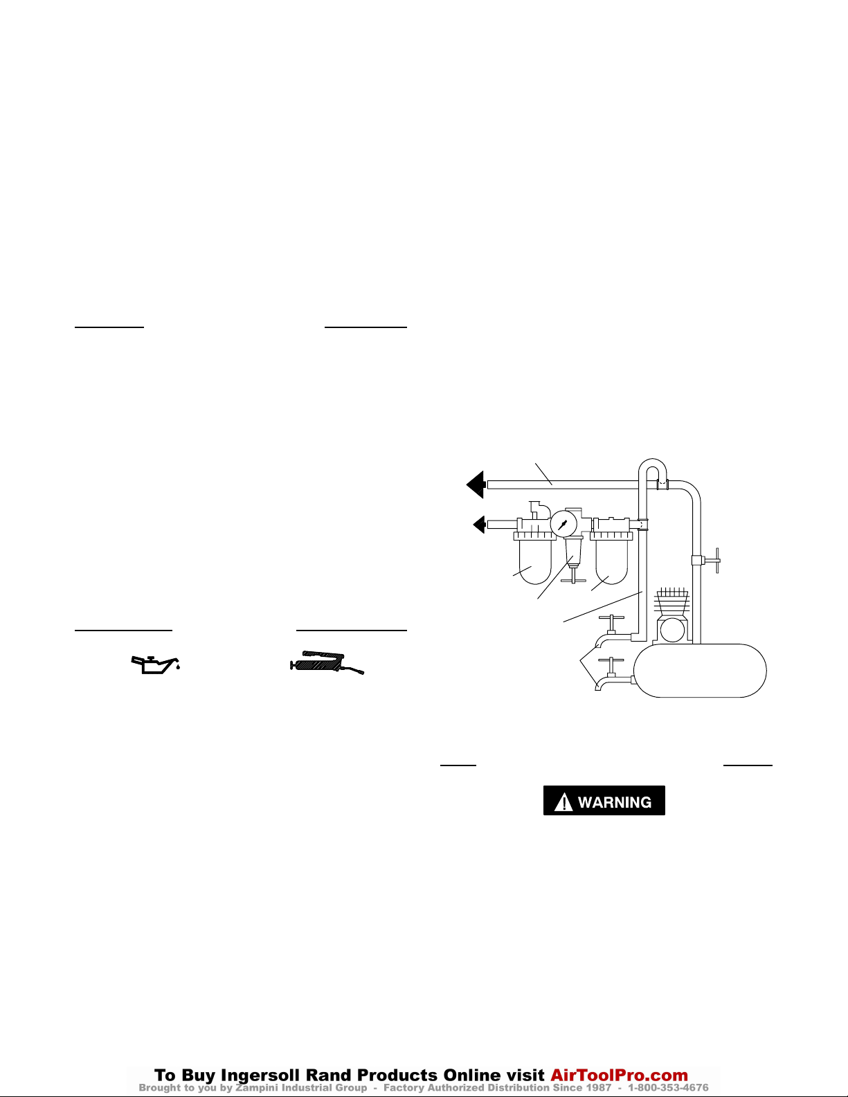
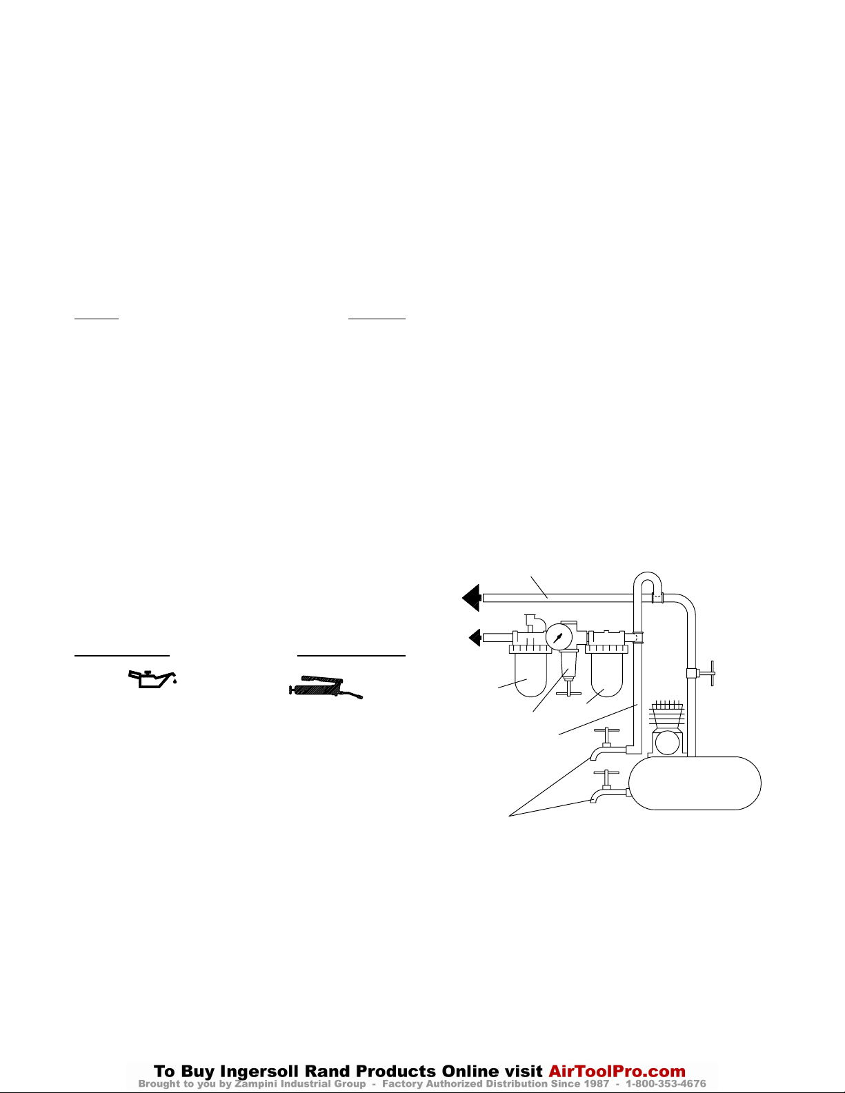
and are tightly secured. See Dwg. TPD905–1 for a
typical piping arrangement.
• Always use clean, dry air. Dust, corrosive fumes
and/or excessive moisture can ruin the motor of an
air tool and affect performance.
• Use only lubricants recommended by
Ingersoll–Rand. Do not lubricate tools with
flammable or volatile liquids such as kerosene,
diesel or jet fuel.
• Do not remove any labels. Replace any damaged
label.
USING THE TOOL
• Always wear eye protection when operating or
performing maintenance on this tool.
• Always wear hearing protection when operating
this tool.
• Use other personal protective equipment such as
gloves, apron and helmet when necessary.
• Keep hands, loose clothing and long hair away from
rotating end of tool.
• Anticipate and be alert for sudden changes in
motion during start up and operation of any power
tool.
• Keep body stance balanced and firm. Do not
overreach when operating this tool. High reaction
torques can occur at or below the recommended air
pressure.
• Tool accessories may continue to rotate briefly after
throttle is released.
• Air powered tools can vibrate in use. Vibration,
repetitive motions or uncomfortable positions may
be harmful to your hands and arms. Stop using any
tool if discomfort, tingling feeling or pain occurs.
Seek medical advice before resuming use.
Always release throttle in case of energy supply
failure.
• Use accessories recommended by Ingersoll–Rand.
• Do not use in explosive atmospheres or on explosive
or flammable materials.
• Do not cut into electrical cables. This tool is not
insulated against contact with electric power
sources.
• This tool is not designed for working in explosive
atmospheres.
• This tool is not insulated against electric shock.
The use of other than genuine Ingersoll–Rand replacement parts may result in safety hazards, decreased tool
performance, and increased maintenance, and may invalidate all warranties.
Repairs should be made only by authorized trained personnel. Consult your nearest Ingersoll–Rand Authorized
Servicenter.
Refer All Communications to the Nearest
Ingersoll–Rand Office or Distributor.
Ingersoll–Rand Company 1999
Printed in U.S.A.
Page 2

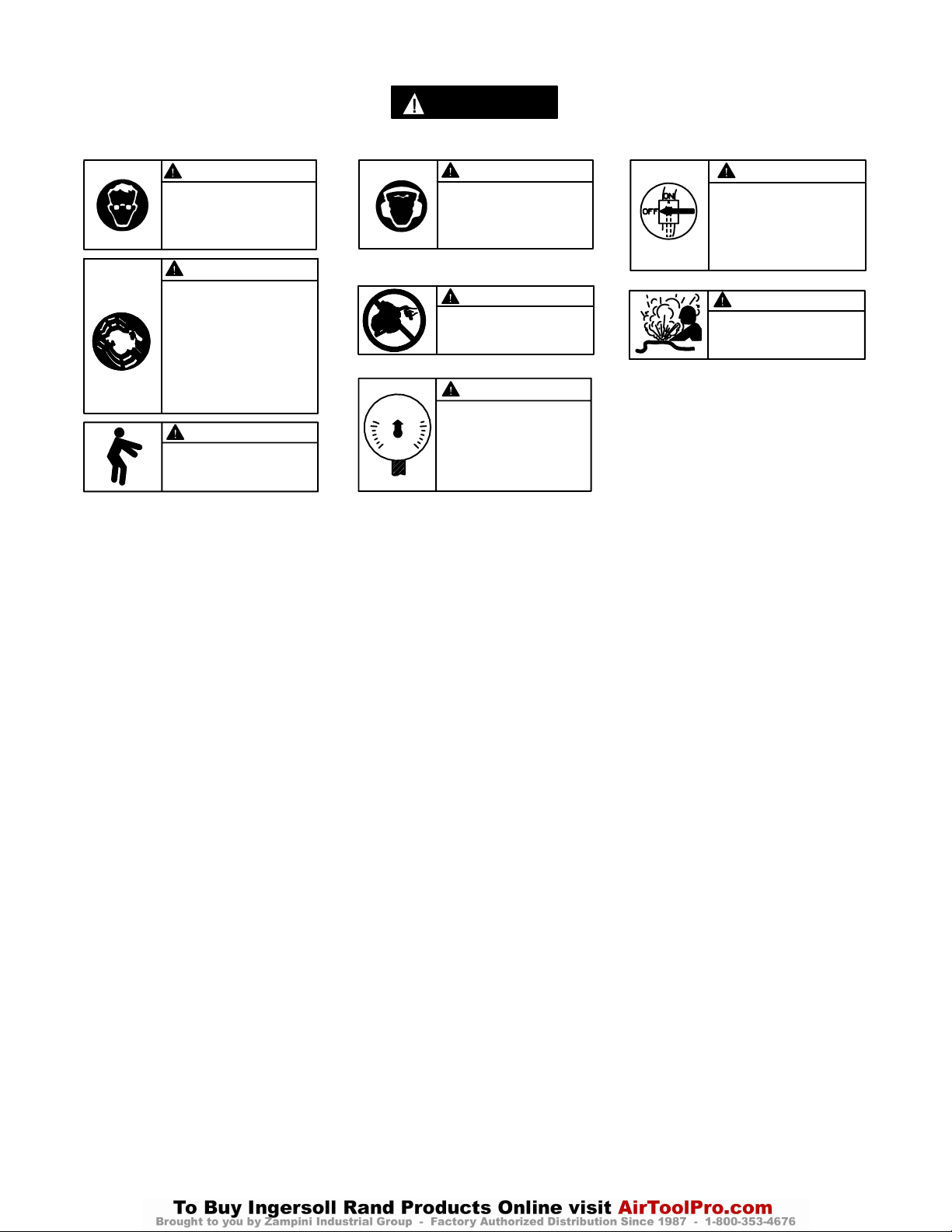
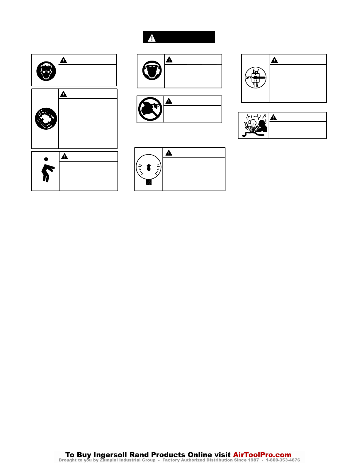
WARNING LABEL IDENTIFICATION
FAILURE TO OBSERVE THE FOLLOWING WARNINGS COULD RESULT IN INJURY.
WARNING
Always wear eye protection
when operating or performing maintenance on this
tool.
WARNING
Air powered tools can vibrate
in use. Vibration, repetitive
motions or uncomfortable positions may be harmful to your
hands and arms. Stop using
any tool if discomfort, tingling
feeling or pain occurs. Seek
medical advice before resuming use.
90 psig
(6.2bar/620kPa)
WARNING
Keep body stance balanced
and firm. Do not overreach
when operating this tool.
USING THE TOOL (Continued from page 1)
• Make sure that sparks, if emitted, are directed so as
not to cause a hazard.
• Keep work area clean. Cluttered areas and benches
invite injuries.
• Keep work area well lit.
• Keep children away. Do not let visitors touch the
tool.
• Store idle tools. When not in use, tools should be
stored in a dry, high or locked place, out of reach of
children.
SAW SPECIFIC WARNINGS
WARNING
Always wear hearing
protection when operating
this tool.
WARNING
Do not carry the tool by
the hose.
WARNING
Operate at 90 psig (6.2 bar/
620 kPa) Maximum air pressure.
• Use the right tool. Do not force small tools or
attachments to do the job of a heavy duty tool. Do
not use tools for purposes not intended.
• Secure work. Use clamps or a vise to hold the work.
• Remove adjusting keys and wrenches before using.
• Stay alert. Watch what you are doing. Use
common sense. Do not operate tool when you are
tired.
WARNING
Always turn off the air supply and disconnect the air
supply hose before installing, removing or adjusting
any accessory on this tool,
or before performing any
maintenance on this tool.
WARNING
Do not use damaged, frayed
or deteriorated air hoses
and fittings.
• Do not use a Saw without the proper guards.
• Do not use a blade for which the recommended
speed is lower than the actual free speed of the Saw.
• Moveable guards must not be locked in the open
position. Ensure that moveable guards operate
freely without jamming and that the retraction
mechanism operates freely.
• Do not use a blade larger than 8–1/4” outside
diameter with a Model S80 Saw.
• Before mounting a blade, after all tool repairs and
whenever a Saw is issued for use, check the free
speed of the Saw with a tachometer to make certain
its actual speed at 90 psig (6.2 bar/620 kPa) does not
exceed the rated free speed stamped on the
nameplate by more than 500 rpm.
• Inspect all blades for chips or cracks prior to
mounting. Do not use a blade that is chipped or
cracked or otherwise damaged.
• Before mounting or removing a blade, disconnect
the Saw from the air supply line, or shut off the air
supply and drain the hose.
• Make certain the blade properly fits the arbor. The
blade should not fit too snugly or too loosely. Do not
use reducing bushings to adapt a blade to any arbor
unless such bushings are supplied by and
recommended by the blade manufacturer.
• Always wear protective eyewear or a face shield
when operating a Saw. Also, use a face mask or dust
mask if the cutting operation produces an excessive
amount of dust. Use local exhaust venting if
needed.
• Always replace a damaged, bent or severely worn
guard.
• Always use clean, sharp blades. A dull blade and/or
a blade with a buildup of gum and hardened pitch
will not cut efficiently. Clean the blade with either
mineral spirits or warm soap and water and dry
thoroughly.
• Use the proper style blade for the application.
• Do not carry a Saw with the motor running.
2
Page 3
SAW SPECIFIC WARNINGS (Continued)
• Keep hands and clothing away from the blade. The
blade of a Circular Saw will coast before stopping
after the throttle is released.
• Do not stop rotation of blade by putting lateral
pressure on it.
• Operate the Saw only when standing on a stable
platform and holding the Saw with two hands. Do
not operate the Saw while standing on a ladder.
• Rest the guide plate fully on the workpiece when
operating.
• Do not force the Saw into the workpiece. The Saw
may kick back if the blade is forced or pinched
while making a cut.
PLACING TOOL IN SERVICE
OILER ADJUSTMENT
The built–in lubricator has been properly adjusted at the
factory to produce the correct amount of lubrication for the
tool. Insufficient lubrication can result from clogged oiler
felts within the lubricator. To replace the felts, proceed as
follows:
1. Remove the Oiler Plug and pour the oil from the oil
chamber.
2. Remove the wool from the chamber with tweezers.
3. With a thin blade screwdriver, remove the Oiler
Adjustment Screw.
4. Using tweezers or a bent piece of wire, remove the
Oiler Felts and install a new set.
5. Replace the Oiler Adjusting Screw, installing it slightly
below flush, and replace the wool.
6. Replenish the oil supply.
• Always use genuine Ingersoll–Rand Flanges
provided with the Saw. Never use a substitute.
• Mount the blade and flanges as instructed in this
manual. Always mount the blade so that the arrow
on the blade and the arrow on the Swing Guard
point in the same direction.
• Never operate the Saw without the Flange
Retaining Screw installed in its proper place in the
end of the Arbor. Always securely tighten the
Flange Retaining Screw as instructed in this manual
before operating the Saw.
• Do not use saws in a bench mounted configuration.
Fill an empty Gear Case with 3 cc of Ingersoll–Rand
No. 28 Grease, and replenish the supply after every six
months, whichever occurs more frequently.
After each year of service, clean all grease from the Gear
Case and replace it with 3 cc of fresh Ingersoll–Rand
No. 28 Grease.
MAIN LINES 3 TIMES
AIR TOOL INLET SIZE
TO
AIR
SYSTEM
TO
AIR
TOOL
LUBRICATOR
REGULATOR
FILTER
LUBRICATION
Ingersoll–Rand No. 50 Ingersoll–Rand No. 28
Ingersoll–Rand No. 100
Always use an air line lubricator with these tools. We
recommend the following Filter–Lubricator–Regulator
Unit:
For USA – No. C31–06–G00
Where a permanent lubricator cannot be installed,
inject 1.5 cc of Ingersoll–Rand No. 50 Oil into the air inlet
before attaching the hose. Remove the Oiler Plug from the
Motor Housing and fill the chamber.
After each eight hours of operation, replenish the oil
supply. Periodically, lubricate the Bevel Bracket, Depth
Bracket and all slides and pivots with Ingersoll–Rand
No. 28 Grease or a light oil.
BRANCH LINE 2 TIMES
AIR TOOL INLET SIZE
DRAIN REGULARLY
COMPRESSOR
(Dwg. TPD905–1)
CONTROLLER INFORMATION
Do not attempt to disassemble the Controller.
The Controller is available only as a unit and is guaranteed
for the life of the tool if it is not abused.
Prior to assembly, carefully inspect the Controller
Assembly for nicks, gouges and dents. Replace it with a
new Controller Assembly if necessary. Test the free speed
before applying a blade.
3
Page 4

PLACING TOOL IN SERVICE
SAW BLADES
Removal
1. Grasp the flats of the Outer Blade Flange with an
adjustable wrench to keep the Blade Arbor from
rotating.
2. Using the Retaining Screw Wrench inserted into the
Flange Retaining Screw, unscrew and remove the
Flange Retaining Screw.
3. Remove the Outer Blade Flange from the Blade Arbor.
4. Retract the Swing Guard and withdraw the Blade
through the Base.
Installation
1. Retract the Swing Guard and insert the Blade up
through the Base, making sure the teeth on the Blade
point in the direction in which the Blade will rotate
(counter–clockwise when facing the blade side of the
tool).
2. Slip the Blade over the Blade Arbor followed by the
Outer Blade Flange. Align the splines on the Blade
Arbor.
3. Screw the Flange Retainer Screw into the end of the
Blade Arbor.
4. Use an adjustable wrench to grasp the flats of the Outer
Blade Flage to keep the Blade Arbor from rotating.
Using the Retaining Wrench inserted into the Flange
Retaining Screw, tighten the Screw between 20 and
25 ft–lb (27 and 34 Nm) torque.
Setting the Depth of Cut
1. Grasp the Throttle Handle with one hand and loosen
the Knob with the other.
2. Hold the base and lift the motor and guard by the
Throttle Handle until the desired depth is indicated on
the scale scribed on the edge of the depth bracket.
3. Securely tighten the Knob.
Setting the Angle of Cut
1. Loosen theTilt Knob.
2. Tilt the motor and Guard on the Base until the desired
setting is obtained as shown on the scale scribed on the
edge of the Front Tilt Sector.
3. Tighten the Tilt Knob.
Sighting and Sawing
1. Open the throttle wide by squeezing the Throttle Lever
in the Handle.
2. Align the mark to be followed with the scribeline in the
Base and push the saw forward. The Swing Guard will
retract into the Stationary Guard as the Blade enters the
material to be cut.
3. When the cut is finished, release the Throttle Lever and
lift the Saw from the work. The Swing Guard will
immediately swing out of the Stationary Guard to
cover the Saw Blade.
HOW TO ORDER AN AIR CIRCULAR SAW
Model Free Speed, rpm Wheel Size (dia.) Weight without Blade
in mm kg lb
S80 4 000 8–1/4 210 6.6 14.5
4
Page 5

F
TPD1722
La scie circulaire pneumatique Modèle S80, lorsqu’utilisée avec la lame appropriée, peut être
utilisée par les entrepreneurs pour découper le béton, le granit, les grosses sections d’aluminium,
les tubes en acier, le bois, les planches, etc. Comme elle ne comporte pas de câble électrique, cette
scie convient bien aux chantiers navals et aux environnements humides.
Ingersoll-Rand ne peut être tenu responsable de la modification des outils par le client pour les
adapter à des applications qui n’ont pas été approuvées par Ingersoll-Rand.
LE NON RESPECT DES AVERTISSEMENTS SUIVANTS PEUT CAUSER DES BLESSURES.
MISE EN SERVICE DE L’OUTIL
• Toujours exploiter, inspecter et entretenir cet outil
conformément au Code de sécurité datiques portatifs de
l’American National Standards Institute (ANSI B186.1).
• Pour la sécurité, les performances optimales et la
durabilité maximale des pièces, cet outil doit être
connecté à une alimentation d’air comprimé de 6,2 bar
(620 kPa) maximum à l’entrée, avec un flexible de 19 mm
de diamètre intérieur.
Le fonctionnement à des pressions d’air comprimé
supérieures causera une vitesse excessive et pourra
causer des blessures.
• Couper toujours l’alimentation d’air comprimé et
débrancher le flexible d’alimentation avant d’installer,
déposer ou ajuster tout accessoire sur cet outil, ou
d’entreprendre une opération d’entretien quelconque sur
l’outil.
• Ne pas utiliser des flexibles ou des raccords endommagés,
effilochés ou détériorés.
• S’assurer que tous les flexibles et les raccords sont
correctement dimensionnés et bien serrés. Voir Plan
TPD905-1 pour un exemple type d’agencement des
tuyauteries.
• Utiliser toujours de l’air comprimé sec. La poussière, les
fumées corrosives et/ou une humidité excessive peuvent
endommager le moteur d’un outil pneumatique et
affecter ses performances.
• Utiliser seulement les lubrifiants recommandés par
Ingersoll-Rand. Ne jamais lubrifier les outils avec des
liquides inflammables ou volatiles tels que le kérosène, le
gasoil ou le carburant d’aviation.
• Ne retirer aucune étiquette. Remplacer toute étiquette
endommagée.
SCIE CIRCULAIRE PNEUMATIQUE MODÈLE S80
NOTE
ATTENTION
D’IMPORTANTES INFORMATIONS DE SÉCURITÉ SONT JOINTES.
LIRE CE MANUEL AVANT D’UTILISER L’OUTIL.
L’EMPLOYEUR EST TENU DE COMMUNIQUER LES INFORMATIONS
DE CE MANUEL AUX EMPLOYÉS UTILISANT CET OUTIL.
UTILISATION DE L’OUTIL
• Porter toujours des lunettes de protection pendant
l’utilisation et l’entretien de cet outil.
• Porter toujours une protection acoustique pendant
l’utilisation de cet outil.
Utiliser d’autres équipements de protection tels que des
gants, un tablier et un casque lorsque nécessaire.
• Tenir les mains, les vêtements flous et les cheveux longs,
éloignés de l’extrémité rotative de l’outil.
• Prévoir, et ne pas oublier, que tout outil motorisé est
susceptible d’à-coups brusques lors de sa mise en marche et
pendant son utilisation.
• Garder une position équilibrée et ferme. Ne pas se pencher
trop en avant pendant l’utilisation de cet outil. Des couples
de réaction élevés peuvent se produire à, ou en dessous, de la
pression d’air recommandée.
• La rotation des accessoires de l’outil peut continuer pendant
un certain temps après le relâchement de la gâchette.
• Les outils pneumatiques peuvent vibrer pendant l’utilisation.
Les vibrations, les mouvements répétitifs et les positions
inconfortables peuvent causer des douleurs dans les mains et
les bras. N’utiliser plus d’outils en cas d’inconfort, de
picotements ou de douleurs. Consulter un médecin avant de
recommencer à utiliser l’outil.
Relâcher toujours la commande en cas de panne
d’alimentation d’énergie.
• Utiliser les accessoires recommandés pa r Ingersoll-Rand.
• Ne pas utiliser cet outil dans des atmosphères explosives ou
sur des matériaux explosifs ou inflammables.
• Prendre soin de ne pas couper des câbles électriques. Ces
outils ne sont pas isolés contre les contacts avec les sources
d’alimentation électrique.
• Cet outil n’est pas conçu pour fonctionner dans des
atmosphères explosives.
• Cet outil n’est pas isolé contre les chocs électriques.
MANUEL D’EXPLOITATION ET D’ENTRETIEN
NOTE
L’utilisation de rechanges autres que les pièces d’origine Ingersoll-Rand peut causer des risques d’insécurité, réduire l e s
performances de l’outil et augmenter l’entretien, et peut annuler toutes les garanties.
Les réparations ne doivent être effectuées que par des réparateurs qualifiés autorisés. Consultez votre Centre de Service
Ingersoll-Rand le plus proche.
Adressez toutes vos communications au Bureau
Ingersoll–Rand ou distributeur le plus proche.
Ingersoll–Rand Company 1999
Imprimé au Royaume–Uni.
Page 6
SIGNIFICATION DES ETIQUETTES D’AVERTISSEMENT
ATTENTION
LE NON RESPECT DES AVERTISSEMENTS SUIVANTS PEUT CAUSER DES BLESSURES.
ATTENTION ATTENTION
Porter toujours des lunettes
de protection pendant
l’utilisation et l’entretien de
cet outil.
ATTENTION
Les outils pneumatiques
peuvent vibrer pendant
l’exploitation. Les vibrations,
les mouvements répétitifs et les
positions inconfortables
peuvent causer des douleurs
dans les mains et les bras.
N’utiliser plus d’outils en cas
d’inconfort, de picotements ou
de douleurs. Consulter un
médecin avant de recommencer
à utiliser l’outil.
90 psig
(6.2bar/620kPa)
ATTENTION
Garder une position équilibrée et
ferme. Ne pas se pencher trop
en avant pendant
l’utilisation de cet outil.
UTILISATION DE L’OUTIL (suite)
• Lorsque des étincelles sont produites, s’assurer qu’elles
sont dirigées de manière à ne pas causer de risques.
• Maintenir le lieu de travail propre. Les zones et les
établis encombrés peuvent être cause de blessures.
• Assurer un éclairage adéquat de la zone de travail.
• Tenir les enfants éloignés. Ne laisser pas les visiteurs
toucher l’outil.
• Ranger les outils non utilisés. Lorsqu’ils ne sont pas
utilisés, les outils doivent être rangés dans un endroit sec
et fermé hors de portée des enfants.
AVERTISSEMENTS SPECIFIQUES AUX SCIES
• Ne jamais utiliser une scie sans protège-lame.
• Ne jamais utiliser une lame dont la vitesse recommandée
est inférieure à la vitesse à vide de la scie.
• Les carters mobiles ne doivent jamais être bloqués en
position ouverte. S’assurer que les carters de protection
fonctionnent librement sans blocage et que le mécanisme
de rappel fonctionne librement.
• Ne jamais utiliser une lame dont le diamètre extérieur
dépasse 8–1/4” sur la scie Modèle S80.
• Avant de monter une lame, après toute réparation de
l’outil ou avant de fournir une scie pour utilisation,
vérifier la vitesse à vide de la scie avec un tachymètre
pour s’assurer que la vitesse réelle à 6,2 bar (620 kPa) ne
dépasse pas de plus de 500 tr/mn la vitesse à vide
nominale poinçonnée sur la plaque signalétique.
• Avant de les monter, vérifier que les lames sont exemptes
de fissures ou d’endommagement. Ne jamais utiliser une
lame écaillée, fissurée ou ayant un endommagement
quelconque.
• Avant de monter ou de démonter une lame, déconnecter
la scie de l’alimentation d’air comprimé, ou couper
l’alimentation d’air comprimé et purger le flexible.
ATTENTION
Porter toujours une
protection acoustique
pendant l’utilisation de cet
outil.
ATTENTION
Ne pas transporter l’outil
par son flexible.
Couper toujours l’alimentation
d’air comprimé et débrancher le
flexible d’alimentation avant
d’installer, déposer ou ajuster
tout accessoire sur cet outil, ou
d’entreprendre une opération
d’entretien quelconque sur l’outil.
ATTENTION
Ne pas utiliser des flexibles ou
des raccords endommagés,
effilochés ou détériorés.
ATTENTION
Utiliser de l’air comprimé
à une pression maximum
de 6,2 bar (620 kPa).
• Utiliser l’outil correct. Ne jamais forcer un petit outil ou
accessoire à effectuer la tâche d’un outil à usage intensif.
Ne jamais utiliser l’outil à des fins auxquelles il n’est pas
destiné.
• Fixer les pièces. Utiliser des brides ou un étau pour fixer
les pièces.
• Retirer les clés de réglage avant d’utiliser l’outil.
• Rester vigilant. Demeurer attentif pendant le travail. Ne
pas prendre de risque. Ne pas utiliser l’outil en cas de
fatigue.
• S’assurer que la lame se monte correctement sur l’arbre.
Elle ne doit pas être trop serrée ni trop libre. Ne jamais
utiliser de bagues de réduction pour adapter une lame
sur un arbre particulier à moins que ces bagues soient
fournies et recommandées par le fabricant de la lame.
• Porter toujours des lunettes ou un masque de protection
lors de l’utilisation d’une scie. De plus, porter un masque
de visage ou un masque anti-poussière si l’opération de
coupe produit une quantité excessive de poussière.
Utiliser le système d’échappement à l’air libre local si
nécessaire.
• Remplacer toujours un protège-lame endommagé, tordu
ou présentant une usure excessive.
• Utiliser toujours des lames propres et affûtées. Une lame
émoussée et/ou couverte de gomme ou de dépôts durs ne
coupera pas efficacement. Nettoyer la lame avec des
essences minérales ou de l’eau chaude savonneuse, et la
sécher soigneusement.
• Utiliser le style correct de lame pour l’application.
• Ne jamais transporter une scie lorsque le moteur est en
marche.
6
Page 7
AVERTISSEMENTS SPECIFIQUES AUX SCIES (suite)
• Tenir les mains et les vêtements éloignés de la lame. La
lame d’une scie circulaire continue à tourner pendant un
certain temps après le relâchement de la gâchette.
• Ne jamais arrêter la rotation de la lame en appliquant
une pression latérale sur celle-ci.
• Utiliser la scie en adoptant une position ferme sur une
plate-forme stable et en tenant la scie avec deux mains.
Ne jamais utiliser la scie debout sur une échelle.
• Appuyer complètement la plaque de guidage contre la
pièce pendant le sciage.
• Ne pas forcer la scie dans la pièce à scier. La sice peut
reculer brusquement si la lame est forcée ou se coince
pendant la coupe.
MISE EN SERVICE DE L’OUTIL
• Utiliser toujours les flasques Ingersoll-Rand d’origine
fournis avec la scie. Ne jamais utiliser de remplacement.
• Monter la lame et les flasques en observant les
instructions de ce manuel. Monter la lame de manière à
ce que la flèche sur la lame et la flèche du protège-lame
pivotant soient dans le même sens.
• Ne jamais utiliser une scie si la vis de retenue du flasque
n’est pas correctement installée en bout d’arbre. Serrer
toujours fermement la vis de retenue du flasque comme
indiqué dans ce manuel avant de mettre la scie en
marche.
• Ne pas utiliser les scies dans une configuration de
montage sur établi.
REGLAGE DU HUILEUR
Le lubrificateur incorporé a été ajusté correctement en usine
pour produire la quantité correcte de lubrification de l’outil.
Une lubrification insuffisante peut être causé par le
colmatage des feutres dans le lubrificateur. Pour remplacer
les feutres, procéder comme suit :
1. Déposer le bouchon de vidange et vider l’huile de la
chambre d’huile.
2. Retirer la laine de la chambre à l’aide d’une pincette.
3. Déposer la vis de réglage du huileur à l’aide d’un
tournevis à lame fine.
4. Déposer les feutres d’huile avec des pinces à épiler ou
un fil de fer recourbé et monter un nouveau jeu de
feutres.
5. Remonter la vis de réglage du huileur en la vissant
légèrement en dessous de la position affleurante, et
remplacer la laine.
6. Remplir la réserve d’huile.
LUBRIFICATION
Ingersoll–Rand No. 50 Ingersoll–Rand No. 28
Ingersoll–Rand No. 100
Utiliser toujours un lubrificateur avec ces outils. Nous
recommandons l’emploi du filtre–régulateur–lubrificateur
suivant :
É.U. – No. C31–06–G00
Lorsqu’un lubrificateur permanent ne peut pas être
installé, injecter environ 1,5 cm3 d’huile Ingersoll–Rand
No. 50 dans le raccord d’admission avant de connecter le
flexible. Déposer le bouchon de vidange du corps du
moteur et remplir la chambre d’huile.
Toutes les huit heures de fonctionnement, remplir la
réserve d’huile. Périodiquement, lubrifier le guide d’angle,
le guide de profondeur, toutes les glissières et tous les
pivots avec de la graisse Ingersoll–Rand No. 28 ou de
l’huile légère.
Remplir un boîtier d’engrenages vide avec 3 cm3 de graisse
Ingersoll–Rand No. 28, ou refaire le plein au moins tous les
six mois si nécessaire.
Après chaque année de service, enlever toute la graisse du
boîtier d’engrenages et la remplacer par 3 cm3 de graisse
Ingersoll–Rand No. 28 neuve.
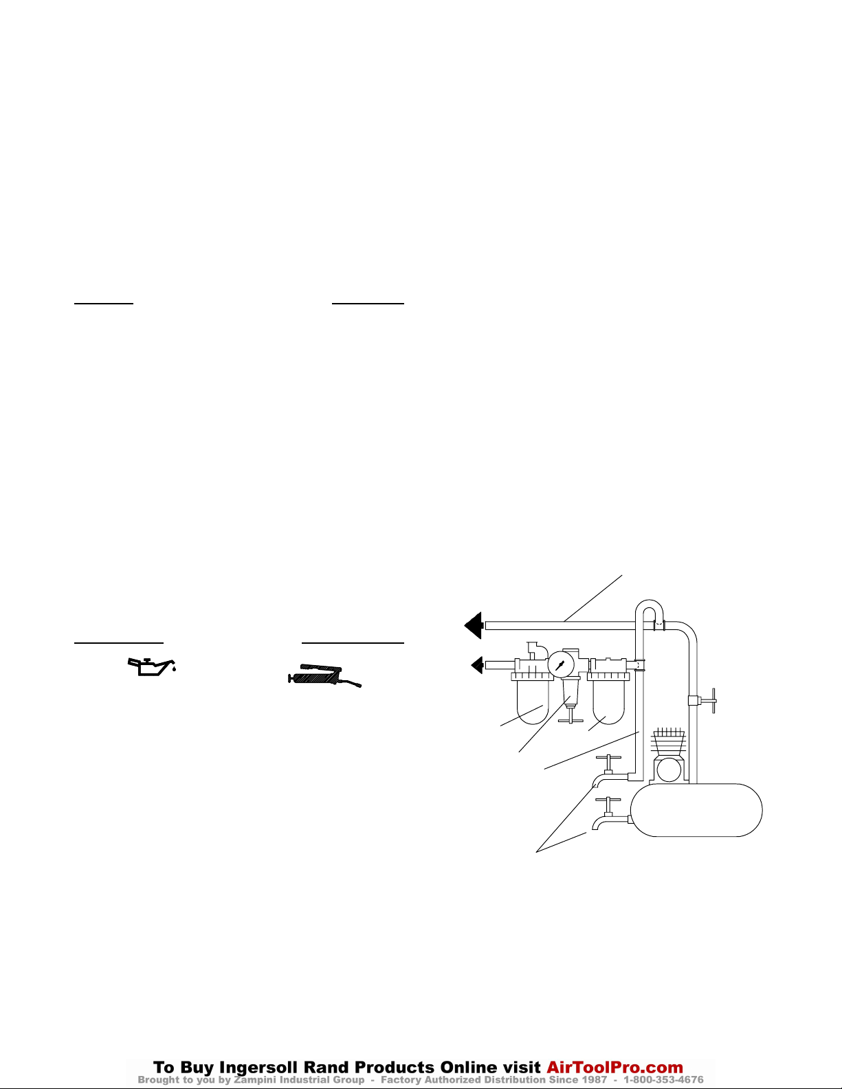
TUYAUTERIE PRINCIPALE
AU MOINS 3 FOIS LA DIMEN-
VERS LE
RÉSEAU D’AIR
COMPRIMÉ
VERS
L’OUTIL
PNEU-
MATIQUE
LUBRIFICATEUR
RÉGULATEUR
LIGNE SECONDAIRE AU
MOINS 2 FOIS LA DIMEN-
SION DE L’ADMISSION
D’AIR DE L’OUTIL
VIDANGER
RÉGULIÈREMENT
SION DE L’ADMISSION D’AIR
DE L’OUTIL
FILTRE
COMPRESSEUR
(Plan TPD905–1)
7
Page 8

MISE EN SERVICE DE L’OUTIL
INFORMATIONS CONCERNANT LE
CONTROLEUR
ATTENTION
Ne jamais essayer de démonter le contrôleur.
Ce dernier est fourni seulement comme un ensemble et est
garanti pendant toute la durée de vie de l’outil s’il est utilisé
correctement.
Avant l’assemblage, vérifier que le contrôleur est exempt de
coups, de rayures et de déteriorations. Le remplacer par un
ensemble de contrôleur neuf si nécessaire. Tester la vitesse
à vide avant de monter une lame.
LAMES DE SCIES
Dépose
1. Saisir les plats du flasque extérieur de lame avec une
clé pour empêcher la rotation de l’arbre porte–lame.
2. Insérer la clé de vis de retenue dans la vis du flasque et
déposer la vis de retenue.
3. Déposer le flasque extérieur de lame de l’arbre
porte–lame.
4. Relever le protège–lame pivotant et retirer la lame à
travers la semelle.
Installation
1. Relever le protège–lame pivotant et introduire la lame
à travers la semelle, en vérifiant que les dents de la
lame sont bien dirigées dans le sens de rotation de la
lame (sens inverse des aiguilles d’une montre lorsque
vu du côté lame de l’outil).
2. Monter la lame sur l’arbre porte–lame puis le flasque
extérieur de lame. Aligner les cannelures sur l’arbre
porte–lame.
3. Visser la vis de retenue du flasque dans l’extrémité de
l’arbre porte–lame.
4. Placer une clé à molette sur les plats du flasque
extérieur de lame pour empêcher la rotation de l’arbre
porte–lame. Insérer la clé de vis de retenue dans la vis
et serrer cette dernière à un couple compris entre 27 et
34 Nm.
Réglage de la profondeur de coupe
1. Saisir la poignée de commande d’une main et desserrer
le bouton de l’autre.
2. Tenir la base et soulever le moteur et le carter par la
poignée de commande jusqu’à ce que la profondeur
désirée soit indiquée sur l’échelle gravée sur le bord du
support de profondeur.
3. Serrer fermement le bouton.
Réglage de l’angle de coupe
1. Desserrer le bouton d’inclinaison.
2. Incliner le moteur et le protège–lame par rapport à la base
jusqu’à ce que l’angle désiré soit obtenu sur l’échelle
graduée sur le bord du secteur d’inclinaison.
3. Serrer le bouton d’inclinaison.
Positionnement et sciage
1. Ouvrir la commande à fond en appuyant sur le levier de
commande de la poignée.
2. Aligner le trait à suivre par rapport au repère gravé sur
la base et pousser la scie vers l’avant. Le protège–lame
pivotant rentrera dans le protège–lame stationnaire lorsque
la lame entre dans le matériau à scier.
3. Lorsque la coupe est terminée, relâcher le levier de
commande et soulever la scie de la pièce. Le
protège–meule pivotant se rabattra automatiquement pour
recouvrir la lame de scie.
SPÉCIFICATIONS
Modèle Vitesse à vide Diamètre de la lame Poids sans lame
tr/mn pouces mm lb. Kg.
S80 4 000 8–1/4 210 14,5 6,6
8
Page 9

MANUAL DE FUNCIONAMIENTO PARA
SIERRA CIRCULAR NEUMATICA
MODELO S80
E
TPD1722
NOTA
La Sierra Circular Neumática Modelo S80, cuando se usa con la hoja apropiada, puede ser usada
por contratistas para cortar hormigón, granito, secciones pesadas de aluminio, tubos de acero,
maderas, tablas, etc. Son ideales para trabajo de astilleros y ambientes mojados, porque son
inalámbricas.
Ingersoll–Rand no aceptará responsabilidad alguna por la modificación de las herramientas
efectuada por el cliente para las aplicaciones que no hayan sido consultadas con Ingersoll–Rand.
AVISO
SE ADJUNTA INFORMACIÓN IMPORTANTE DE SEGURIDAD.
LEA ESTE MANUAL ANTES DE UTILIZAR LA HERRAMIENTA.
ES RESPONSABILIDAD DE LA EMPRESA ASEGURARSE DE QUE
EL OPERARIO ESTÉ AL TANTO DE LA INFORMACIÓN QUE CONTIENE ESTE MANUAL.
EL HACER CASO OMISO DE LOS AVISOS SIGUIENTES PODRÍA OCASIONAR LESIONES.
PARA PONER LA HERRAMIENTA EN SERVICIO
• Utilice, examine y mantenga siempre esta herramienta
conforme al código de seguridad para herramientas
neumáticas portátiles de la American National Standards
Institute (ANSI B186.1).
• Para mayor seguridad, un óptimo rendimiento y la
máxima durabilidad de las piezas, utilice esta
herramienta a una presión máxima de 90 psig
(6,2 bar/620 kPa) con una manguera de suministro de
aire con diámetro interno de 19 mm.
El manejo de la herramienta a una presión de aire
superior resultará en un exceso de velocidad y puede
ocasionar lesiones.
• Corte siempre el suministro de aire y desconecte la
manguera de suministro de aire antes de instalar,
desmontar o ajustar cualquier accesorio de esta
herramienta, o antes de realizar cualquier operación de
mantenimiento de la misma.
• No utilice mangueras de aire y racores dañados,
desgastados o deteriorados.
• Asegúrese de que todos los racores y mangueras sean del
tamaño correcto y estén bien apretados. El Esq.
TPD905–1 muestra una disposición característica de las
tuberías.
• Use siempre aire limpio y seco. El polvo, los gases
corrosivos y/o el exceso de humedad pueden estropear el
motor de una herramienta neumática y perjudicar el
rendimiento.
• Use únicamente lubricantes recomendados por
Ingersoll–Rand. No lubrique las herramientas con
líquidos inflamables o volátiles tales como queroseno,
gasoil o combustible para motores a reacción.
• No saque ninguna etiqueta. Sustituya toda etiqueta
dañada.
UTILIZACIÓN DE LA HERRAMIENTA
• Use siempre protección ocular cuando utilice esta
herramienta o realice operaciones de mantenimiento en
la misma.
• Use siempre protección para los oídos cuando utilice esta
herramienta.
Utilice equipos suplementarios de protección personal, como
guantes, del a n tal y casco , cuando sea necesario.
• Mantenga las manos, la ropa suelta y el cabello largo
alejados del extremo giratorio de la herramienta.
• Anticipe y esté atento a los cambios repentinos en el
movimiento durante la puesta en marcha y utilización de
toda herramien ta motorizada.
• Mantenga una postura del cuerpo equilibrada y firme. No
estire demasiado los brazos al manejar la herrami enta.
Pueden da rse elevados pares de reacción a la presión de aire
recomendada, e incluso a presiones in feriores.
• Los accesorios de la herramienta pued en seguir girando
brevemente después de haberse soltado el mando.
• Las herramientas neumáticas pueden vibrar durante el uso.
La vibración, los movimientos repetitivos o las posiciones
incómodas pueden dañarle los brazos y manos. En caso de
incomodidad, sensación de hormigueo o dolor, deje de usar la
herramienta. Consulte con el médico antes de volver a
utilizarla.
Suelte siempre el mando si se llega a corta r el suministro de
energía.
• Utilice únicamente los accesorios recomendados por
Ingersoll–Rand.
• No utilice esta herramienta en ambientes explosivos ni con
materiales explosivos o inflamables.
• No corte los cables eléctricos. Estas herramientas no están
aisladas contra el contacto con fuentes de alimentación
eléctrica.
• Esta herramienta no ha sido diseñada para trabajar en
ambientes explosivos.
• Esta herramienta no está aislada contra descargas
eléctricas.
NOTA
El uso de piezas de recambio que no sean las auténticas piezas Ingersoll–Rand puede poner en peligro la seguridad, reducir el
rendimiento de la herramienta y aumentar los cuidados de mantenimiento necesarios, así como invalidar toda garantía.
Las reparaciones sólo se deben encomendar a personal debidamente cualificado y autorizado. Consulte con el centro de servicio
autorizado Ingersoll–Rand más próximo.
Toda comunicación se deberá dirigir a la oficina o
al distribuidor Ingersoll–Rand más próximo.
Ingersoll–Rand Company 1999
Impreso en EE. UU.
Page 10
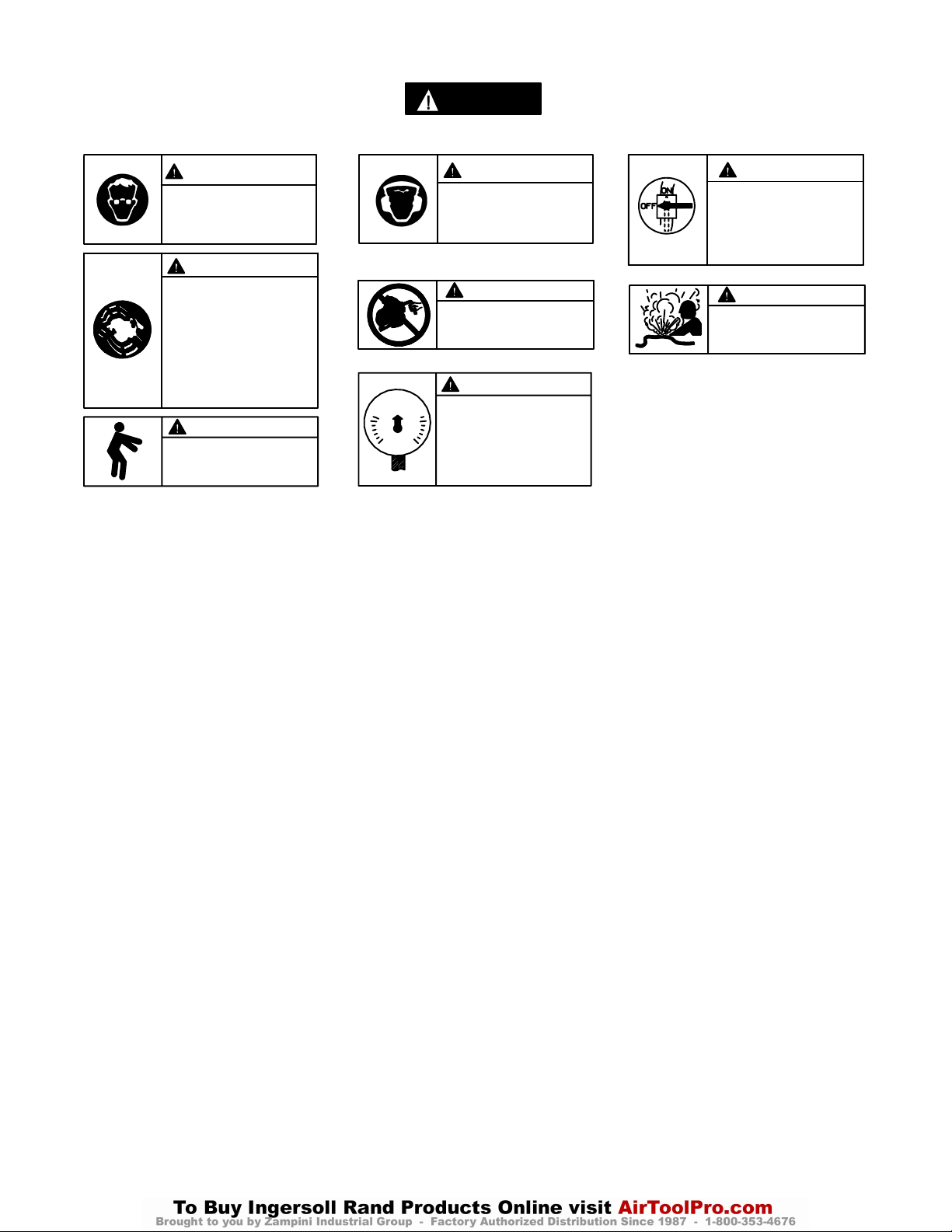
ETIQUETAS DE AVISO
AVISO
EL HACER CASO OMISO DE LOS AVISOS SIGUIENTES PODRÍA OCASIONAR LESIONES.
ADVERTENCIA
Use siempre protección ocular
cuando utilice esta herramienta
o realice operaciones de
mantenimiento en la misma.
Use siempre protección para
los oídos cuando utilice esta
herramienta.
ADVERTENCIA
Las herramientas neumáticas
pueden vibrar durante el uso.
La vibración, los movimientos
repetitivos o las posiciones
incómodas podrían dañarle los
brazos y las manos. En caso
de incomodidad, sensación de
hormigueo o dolor, dejar de
usar la herramienta. Consultar
al médico antes de volver a utilizarla.
ADVERTENCIA
Mantener una postura del cuerpo
equilibrada y firme. No estirar demasiado los brazos al manejar la
herramienta.
90 psig
(6.2bar/620kPa)
No coger la herramienta
por la manguera para levantarla.
Manejar la herramienta a una
presión de aire máxima de 90
psig (6,2 bar/620 kPa).
UTILIZACIÓN DE LA HERRAMIENTA (continúa)
• Cerciórese de que las chispas, en caso de producirse, se
dirijan de modo que no constituya n un peligro.
• Conserve limpio el lugar de trabajo. Los espacios y
bancos de trabajo llenos de estorbos acaban dando lugar
a lesiones.
• Mantenga el lugar de trabajo bien iluminado.
• No permita que se acerquen los niños. No permita que
personas que estén de visita toquen la herra mi enta .
• Guarde las herramientas que no se usen. Cuando no se
estén usando conviene guardar las herramientas en un
lugar seco, alto o cerrado bajo llave, fuera del alcance de
los niños.
ADVERTENCIA
ADVERTENCIA
ADVERTENCIA
Cortar siempre el suministro
de aire y desconectar la manguera de suministro de aire
antes de instalar, retirar o ajustar cualquier accesorio de esta
herramienta, o antes de realizar
cualquier operación de mantenimiento de la misma.
ADVERTENCIA
No utilizar mangueras de aire
y accesorios dañados, desgastados ni deteriorados.
ADVERTENCIA
• Use la herramienta conveniente. No fuerce una
herramienta o accesorio pequeño a hacer el trabajo de
una herramienta pesada. No utilice las herramientas
para fines no previstos.
• Sujete las piezas. Use mordazas o un tornillo de banco
para sostener la pieza.
• Retire las llaves de ajuste antes de utilizar la
herramienta.
• Manténgase alerta. Vigile lo que está haciendo. Use el
sentido común. No utilice la herramienta cuando esté
cansado.
AVISOS ESPECIFICOS DE SIERRAS
• No use una Sierra sin la guarda apropiada.
• No use una hoja que tenga velocidad de uso recomendada
menor de la velocidad libre actual de la herramienta.
• Los protectores móviles no deben bloquearse en la
posición abierta. Cerciórese de que los protectores
móviles funcionen libremente sin atascarse y que el
mecanismo de retracción también funcione libremente.
• No use una hoja mayor de 8–1/4” de diámetro externo
con la Sierra Modelo S80.
• Antes de montar una hoja, y después de todas las
reparaciones de herramienta y siempre que se ofrezca
una Sierra para uso, compruebe la velocidad libre de la
Sierra con un tacómetro para asegurarse que su
velocidad actual a 90 psig
(6,2 bar/620 kPa) no exceda la velocidad libre media de la
placa en más de 500 rpm..
• Inspeccione todas las hojas para ver si tienen grietas o
roturas antes de montarlas. No use una hoja que esté rota
o agrietada o de cualquier otra forma dañada.
• Antes de montar o sacar una hoja, desconecte la sierra de
la línea de suministro de aire, o cierre el suministro de
aire y purgue la manguera.
• Asegúrese que la hoja esté bien fijada en el eje. La hoja
no debe estar muy floja ni muy apretada. No use
casquillos reductores para adaptar una hoja a cualquier
eje a menos que estos hayan sido suministrados y
recomendados por el fabricante de hojas.
• Usar siempre protección ocular o máscara protectora
cuando maneje esta Sierra. También, use una máscara
protectora o antipolvo si la operación de serrar produce
un exceso de polvo. Utilice un sistema local de salida del
aire de escape, si fuese necesario.
• Cambie siempre un guarda dañada, torcido o
severamente desgastado.
• Use siempre hojas limpias y afiladas. Una hoja desafilada
y/o una hoja con una incrustación de cola o alquitrán
endurecido no cortará eficazmente. Limpie la hoja con
aguarrás minerales o con agua caliente con jabón y
séquela bien.
• Use el estilo de hoja apropiado para la aplicación.
• No transporte una Sierra con el motor en marcha.
10
Page 11
AVISOS ESPECIFICOS DE SIERRAS (continúa)
• Mantenga las manos y ropa fuera de la hoja. La hoja de
la Sierra Circular rodará por un tiempo antes de parar
completamente al soltar el estrangulador.
• No presione sobre el costado de la hoja para detenerla.
• Use solamente la Sierra cuando esté sobre una
plataforma estable y sujetando la Sierra con ambas
manos. No use la Sierra mientras está subido a una
escalera.
• Apoye bien la placa guía sobre la pieza a cortar cuando
maneje la herramienta.
• No fuerce la Sierra en la pieza de trabajo. Puede que de
un contragolpe si se fuerza o golpea la hoja mientras se
está haciendo un corte.
PARA PONER LA HERRAMIENTA EN SERVICIO
AJUSTE DEL LUBRICADOR
El lubricador incorporado ha sido ajustado apropiadamente
en la fábrica para producir la cantidad correcta de
lubricación para la herramienta. La lubricación insuficiente
puede ser el resultado de un fieltro obturado de lubricador.
Para cambiar los fieltros proceda como sigue:
1. Saque el tapón del lubricador y vierta el contenido de
la cámara de aceite.
2. Utilice unas pinzas para extraer la lana de la cámara.
3. Con un destornillador de hoja fina, saque el tornillo de
ajuste del lubricador.
4. Utilice pinzas o un trozo de alambre torcido para
extraer los fieltros del lubricador y colocar unos
fieltros nuevos.
5. Coloque nuevamente el tornillo de ajuste del lubricador
de modo que quede ligeramente hundido y coloque la
lana.
6. Reponga el aceite.
LUBRICACIÓN
Ingersoll–Rand Nº 50 Ingersoll–Rand Nº 28
Ingersoll–Rand Nº 100
Utilice siempre un lubricador de aire comprimido con estas
herramientas. Recomendamos el siguiente conjunto de
filtro–lubricador–regulador:
EE.UU. – No. C31–06–G00
Cuando no se pueda instalar un lubricador permanente,
inyecte 1,5 cc de Aceite Ingersoll–Rand Nº 50 en la
admisión de aire antes de conectar la manguera. Saque el
tapón del lubricador de la carcasa del motor y llene la
cámara.
• Use siempre las genuinas Bridas Ingersoll–Rand
suministradas con la Sierra. No use nunca un sustituto.
• Monte la hoja y bridas como se instruye en este manual.
Monte siempre la hoja de forma que la flecha en la hoja y
la flecha en el Guarda Pivote apunten en la misma
dirección.
• No use nunca la Sierra sin el Tornillo Retenedor de Brida
instalado en su lugar apropiado en el extremo de Eje.
Apriete siempre bien el Tornillo Retenedor de Brida
como se instruye en este manual antes de usar la Sierra.
• No utilice una sierra montada en banco.
Tras cada ocho horas de funcionamiento, reponga el
aceite. Lubrique periódicamente el soporte para bisel, el
soporte para profundidad y todas las correderas y pivotes
con aceite Ingersoll–Rand Nº 28 o un aceite ligero.
A la carcasa de engranajes vacía se debe echar 3 cc de grasa
Ingersoll–Rand Nº 28, reponiendo el lubricante cada seis
meses, lo que ocurra primero.
Tras cada año de servicio, elimine toda la grasa de la
carcasa de engranajes y sustitúyala por 3 cc de grasa
Ingersoll–Rand Nº 28 nueva.
TUBERÍAS PRINCIPALES 3
VECES EL TAMAÑO DE
ENTRADA DE HERRAMIENTA
AL SISTEMA
NEUMÁTICO
A LA
HERRA–
MIENTA
NEUMÁTICA
LUBRICADOR
TUBERÍA DE RAMAL
2 VECES EL TAMAÑO
DE ENTRADA DE
HERRAMIENTA
NEUMÁTICA
PURGAR
PERIÓDICAMENTE
NEUMÁTICA
REGULADOR
FILTRO
COMPRESOR
(Esq. TPD905–1)
11
Page 12

PARA PONER LA HERRAMIENTA EN SERVICIO
INFORMACIÓN SOBRE
EL REGULADOR
AVISO
No intente desarmar el regulador.
El regulador sólo se suministra como unidad y está
garantizado por toda la vida útil de la herramienta si se
utiliza como es debido.
Antes de montarlo, examine detenidamente el regulador
para ver si tiene cortes, rayaduras o abolladuras. Sustitúyalo
por un nuevo regulador si fuese necesario. Verifique la
velocidad en vacío antes de instalar la hoja.
HOJAS DE SIERRA
Desmontaje
1. Sujete las partes planas de la brida exterior de la hoja
con una llave ajustable para impedir que gire el eje de
la hoja.
2. Utilice una llave para desenroscar y quitar el tornillo de
retención de la brida.
3. Retire la brida exterior de la hoja del eje de la hoja.
4. Retraiga el protector oscilante y retire la hoja a través
de la base.
Montaje
1. Retraiga el protector oscilante e introduzca la hoja
hacia arriba por la base, asegurándose de que los
dientes de la hoja apunten en el sentido de giro de ésta
(en sentido antihorario mirando hacia el lado de la
herramienta en que va la hoja).
2. Pase la hoja sobre el eje de la hoja, seguido de la brida
exterior de la hoja. Alinee las estrías del eje de la hoja.
3. Enrosque el tornillo de retención de la brida en el
extremo del eje de la hoja.
4. Utilice una llave ajustable para sujetar las superficies
planas de la brida exterior de la hoja a fin de impedir
que gire el eje de la hoja. Apriete con una llave el
tornillo de retención de la brida a 27–34 Nm.
Selección de la profundidad de corte
1. Coja la empuñadura del estrangulador con una mano y
afloje la manilla con la otra mano.
2. Sostenga la base y eleve el motor y el protector por la
empuñadura del estrangulador hasta alcanzar la
profundidad deseada en la escala estampada en el
borde del soporte de profundidad.
3. Apriete la manilla a fondo.
Selección del ángulo de corte
1. Afloje la manilla de corte en ángulo.
2. Incline el motor y el protector de la base hasta que
obtenga la posición deseada tal y como se muestra en la
escala que aparece en el borde del sector de inclinación
delantera.
3. Apriete la manilla de corte en ángulo.
Posicionamiento y para el corte
1. Ponga la herramienta completamente en marcha apretando
para ello la palanca reguladora situada en la empuñadura.
2. Alinee la línea de corte con la línea estampada en la
base de la sierra y empuje la sierra hacia adelante. El
protector oscilante se retirará hacia dentro del protector
estacionario al entrar la hoja en el material que se va a
cortar.
3. Al acabar de cortar, suelte la palanca de mando y saque la
sierra de la pieza en la que se está trabajando. El protector
oscilante se moverá inmediatamente fuera del protector
estacionario para cubrir la hoja de la sierra.
ESPECIFICACIONES
Modelo Velocidad en vacío Tamaño de
Hoja (diám.)
rpm pulg. mm lb. Kg.
S80 4 000 8–1/4 210 14,5 6,6
12
Peso
(hoja excluida)
Page 13

MANUAL DE FUNCIONAMENTO E MANUTENÇÃO PARA
P
SERRA PNEUMÁTICA CIRCULAR
MODELO S80
AVISO
Serra Pneumática Circular Modelo S80, quando usada com a lâmina apropriada, pode ser usada
para cortar concreto, granito, secções pesadas de alumínio, tubagem de aço, toras de
madeiras, etc. Como não há cabos eléctricos, estas serras são ideais para trabalho em
estaleiros e ambientes húmidos.
Ingersoll–Rand não é responsável por modificações, fei t as pelo cliente em ferramentas, nas quais a
Ingersoll–Rand não tenha sido consultada.
ADVERTÊNCIA
INFORMAÇÃO DE SEGURANÇA IMPORTANTE EM ANEXO.
LEIA ESTE MANUAL ANTES DE OPERAR A FERRAMENTA.
É DA RESPONSABILIDADE DO EMPREGADOR COLOCAR A INFORMAÇÃO
DESTE MANUAL NAS MÃOS DO OPERADOR.
O NÃO CUMPRIMENTO DAS SEGUINTES ADVERTÊNCIAS PODE RESULTAR EM FERIMENTOS.
COLOCANDO A FERRAMENTA EM
FUNCIONAMENTO
• Sempre opere, inspeccione e mantenha esta
ferramenta de acordo com o Código de Segurança do
Instituto Americano de Padrões Nacionais para
Ferramentas Pneumáticas Portáteis (ANSI B186.1).
• Para segurança, máximo desempenho e máxima
durabilidade das peças, opere esta ferramenta com
uma pressão de ar máxima de 6,2 bar/620 kP
(90 psig) na entrada da mangueira de alimentação de
ar com diâmetro interno de com 19 mm (3/4”).
• Desligue sempre a alimentação de ar e desconecte a
mangueira de alimentação de ar antes de instalar,
remover ou ajustar qualquer acessório nesta
ferramenta, ou antes de executar qualquer serviço de
manutenção nesta ferramenta.
• Não use mangueiras de ar ou adaptadores danificados,
gastos ou deteriorados.
• Certifique–se de que todas as mangueiras e
adaptadores sejam do tamanho correcto e estejam
apertados com firmeza. Veja o Desenho TPD905–1
para um arranjo típico de tubagem.
• Use sempre ar seco e limpo com pressão máxima de
90 psig. Pó, fumos corrosivos e/ou humidade excessiva
podem arruinar o motor de uma ferramenta pneumática.
• Não lubrifique as ferramentas com líquidos
inflamáveis ou voláteis tais como querosene, diesel ou
combustível de jactos.
• Não remova nenhum rótulo. Reponha qualquer rótulo
danificado.
USANDO A FERRAMENTA
• Use sempre óculos de protecção quando estiver operando
ou executando serviço de manutenção nesta ferramenta.
• Use sempre protecção contra ruído ao operar esta
ferramenta.
• Mantenha as mãos, partes do vestuário soltas e cabelos
compridos afasta dos da extremidade em rotação.
• Antecipe e esteja alerta a mudanças repentinas no
movimento quando ligar e operar qualquer
ferramenta motorizada.
• Mantenha a posição do corpo equilibrada e firme. Não
exagere quando operar esta ferramenta. Torques de
reacção elevados podem ocorrer na ou abaixo da
pressão de ar recomendada.
• O acessório da ferramenta pode continuar a girar
brevemente após a pressão ter sido aliviada.
• Ferramentas accio na das pneumáticamente podem vibrar
em uso. Vibração, movimentos repetitivos ou posições
desconfortáveis podem ser prejudiciais às mãos e aos
braços. Pare de usar a ferramenta caso ocorra algum
desconforto, sensação de formigueiro ou dor. Procure
assistência médica antes de retornar ao trabalho.
• Use acessórios recomendados pela Ingersoll–Rand.
• Esta Ferramenta não foi concebida para trabalhos em
atmosferas explosivas.
• Esta Ferramenta não está isolada contra choques
eléctricos.
AVISO
O uso de peças de substituição que não sejam genuinamente da Ingersoll–Rand podem resultar em riscos de segurança,
diminuição do desempenho da ferramenta, aumento da necessidade de manutenção e pode invalidar todas as garantias.
As reparações devem ser feitas somente por pessoal treinado autorizado. Consulte o Centro de Serviços da Ingersoll–Rand mais
próximo.
Envie Todos os Comunicados Para o Distribuidor ou
Escritório da Ingersoll–Rand Mais Próximo.
Ingersoll–Rand Company 1999
Impresso nos E.U.A.
Page 14
IDENTIFICAÇÃO DO RÓTULO DE ADVERTÊNCIA
ADVERTÊNCIA
O NÃO CUMPRIMENTO DAS SEGUINTES ADVERTÊNCIAS PODE RESULTAR EM FERIMENTOS.
ADVERTÊNCIA
Use sempre óculos de
protecção quando estiver
operando ou executando algum
serviço de manutenção nesta
ferramenta.
ADVERTÊNCIA
Ferramentas accionadas
pneumáticamente podem vibrar
em uso. Vibração, movimentos
repetitivos ou posições
desconfortáveis podem ser
prejudiciais às mãos e aos
braços. Pare de usar a
ferramenta caso ocorra algum
desconforto, sensação de
formigueiro ou dor. Procure
assistência médica antes de
retornar ao trabalho.
ADVERTÊNCIA
Mantenha a posição do corpo
equilibrada e firme. Não
exagere quando operar esta
ferramenta. Torques de reacção
elevados podem ocorrer sob a
pressão de ar recomendada.
90 psig
(6.2bar/620kPa)
Não carregue a ferramenta
segurando na mangueira.
Opere com pressão do ar Máxima
de 90 psig (6,2–6,9 bar).
UTILIZAÇÃO DA FERRAMENTA
(Continuação da página 1)
• Certifique–se de que se forem produzidas faíscas, estas
são dirigidas de forma a não criar um risco à
segurança.
• Mantenha a área de trabalho limpa. Áreas e bancadas
atravancadas constituem um convite a lesões.
• Mantenha a área de trabalho bem iluminada.
• Mantenha as crianças afastadas. Não permita que
visitantes toquem nas ferramentas.
• Guarde ferramentas inactivas. Quando não estiverem
em uso, as ferramentas devem ser guardadas num
ADVERTÊNCIA
Use sempre protecção contra o
ruído ao operar esta ferramenta.
ADVERTÊNCIA
Desligue sempre a alimentação
de ar e desconecte a mangueira
de alimentação de ar antes de
instalar, remover ou ajustar
qualquer acessório nesta
ferramenta, ou antes de
executar algum serviço de
manutenção nesta ferramenta.
ADVERTÊNCIA
ADVERTÊNCIA
Não use mangueiras de ar ou
adaptadores danificados,
gastos ou deteriorados.
ADVERTÊNCIA
local seco, alto ou fechado à chave, longe do alcance
das crianças.
• Utilize a ferramenta correcta. Não force ferramentas
ou acessórios pequenos para realizar a tarefa de uma
ferramenta para trabalho pesado. Não utilize
ferramentas para finalidades não pretendidas.
• Fixe o trabalho. Utilize braçadeiras ou um torno de
bancada para fixar o trabalho.
• Remova chaves de ajuste e chaves inglesas antes de
utilizar a ferramenta.
• Fique alerta. Preste atenção ao que está a fazer.
Empregue o bom senso. Não opere a ferramenta
quando estiver cansado.
ADVERTÊNCIAS ESPECÍFICAS DA SERRA
• Não use a serra sem os protectores adequados.
• Não use uma lâmina para a qual a velocidade
recomendada é inferior à velocidade livre real da Serra .
• As protecções móveis não devem ser travadas na
posição aberta. Certifique–se de que as protecções
móveis funcionam livremente sem encravar e que o
mecanismo de retracção funciona livremente.
• Não use uma lâmina com diâmetro externo maior que
8” com uma Serra Modelo S80.
• Antes de montar uma lâmina, depois de qualquer
reparo de ferramenta ou quando quer que uma Serra
seja colocada em funcionamento, verifique a velocidade
livre da Serra com um tacômetro para se certificar de
que a sua velocidade real a 6,2 bar/620kPa (90 psig)
não exceda a rpm selada ou impressa na placa de
identificação por mais de 50 0 rpm.
• Verifique todas as lâminas para ver se há lascas ou
rachaduras antes da montagem. Não use uma lâmina
que esteja lascada ou rachada ou de alguma maneira
danificada.
• Antes de montar ou remover uma lâmina, desconecte
a Serra da linha de alimentação de ar principal, ou
desligue o suprimento de ar e drene a mangueira.
• Verifique se a lâmina se encaixa na árvore de
montagem. A lâmina não deve se encaixa r muito
apertada ou muito frouxa. Não use rolamentos
reductores para adaptar uma lâmina na árvore de
montagem a não ser que tais rolamentos tenham sido
fornecidos ou recomendados pelo fabricante da lâmina.
• Use sempre proteção para os olhos ou uma máscara
protectora quando estiver operando uma Serra.
Também, use máscara para proteção do rosto ou
contra pó se a operação de corte produz uma
quentidade de pó excessiva.
• Reponha sempre um protector danificado, torto ou
severamente gasto.
• Use sempre lâminas afiadas e limpas. Uma lâmina
gasta e/ou uma lâmina com desgaste, não cortará com
eficiência. Limpe a lâmina ou com líquidos voláteis
minerais ou água com sabão aquecida e seque
completamente.
14
Page 15
ADVERTÊNCIAS ESPECÍFICAS DA SERRA (cont. in Portuguese)
• Use uma lâmina com corte apropriado para a
aplicação.
• Não carregue uma Serra com o motor em
funcionamento.
• Mantenha as mãos e vestuário fora do alcance da
lâmina. A lâmina de uma Serra circular irá acostar
antes de parar depois que a pressão for aliviada.
• Não pare a rotação da lâmina exercendo pressão
lateral sobre a mesma.
• Opere a Serra somente quando estiver de pé em uma
plataforma estável e segurando a Serra com ambas as
mãos. Não opere a Serra enquanto estiver em uma
escada.
w Encoste a placa guia totalmente na peça de trabalho
ao operar a serra.
• Não force a Serra contra a peça em que estiver
trabalhando. A Serra pode repicar se a lâmina for
COLOCANDO A FERRAMENTA EM FUNCIONAMENTO
AJUSTE DO RESERVATÓRIO
DE ÓLEO
O lubrificador embutido foi ajustado adequadamente de
fábrica para produzir uma quantidade de lubrificação
correcta para a ferramenta. Lubrificação insuficiente pode
resulatar dos feltros do reservatório de óleo entupidos
dentro do lubrificador. Para repor os feltros, proceda da
seguinte maneira:
1. Remova o Bujão de Drenagem e despeje o óleo da
câmara de óleo.
2. Remova a lã da câmara com pinças.
3. Com uma chave de fenda fina, remova o Parafuso de
Ajuste do Reservatório de Óleo.
4. Utilizando pinças ou um pedaço curvado de arame,
remova os Feltros do Reservatório de Óleo e instale um
novo conjunto.
5. Recoloque o Parafuso de Ajuste do Reservatório de
Óleo, instalando–o levemente abaixo do escape, e
recoloque a lã.
6. Reabasteça o suprimento de óleo e instale o Bujão de
Drenagem.
LUBRIFICAÇÃO
forçada ou beliscada enquando estiver executando um
corte.
• Use sempre Acessórios Ingersoll–Rand genuínas
fornecidas com a Serra. Nunca use uma flange de
substituição.
• Monte a lâmina e as flanges como instruído neste
manual. Sempre monte a lâmina de modo que a seta
na lâmina e a seta no Protector de Balanço apontem
na mesma direção.
• Nunca opere a Lâmina sem o Parafuso de Retenção da
Flange instalado na posição apropriada na
extremidade da árvore. Aperte sempre com seguraça o
Parafuso de Retenção da Flange como instruído neste
manual antes de operar a Serra.
w Não utilize serras numa configuração montada em
bancada.
Onde um lubrificador permanente não pode ser
instalado, injecte 1,5 cc de Óleo Ingersoll–Rand No. 50 na
entrada de ar antes de conectar a mangueira. Remova o
Bujão de Drenagem do Corpo do Motor e encha a câmara.
Depois de oito horas de operação, reabasteça o
suprimento de óleo. Periodicamente, lubrifique o Pinhão, o
Suporte e todas as peças móveis com Massa Lubrificadora
Ingersoll–Rand No. 28 ou um óleo leve.
Encha a Caixa de Engrenagem vazia com 3 cc de Massa
Ingersoll–Rand No. 28, e reabasteça o suprimento depois de
cada 200 horas de operação ou depois de cada seis meses, o
que ocorrer mais frequentemente.
Depois de cada ano de serviço, limpe toda a massa da
engrenagem e troque–a por 3 a 4 cc de Massa
Ingersoll–Rand No. 28 recente.
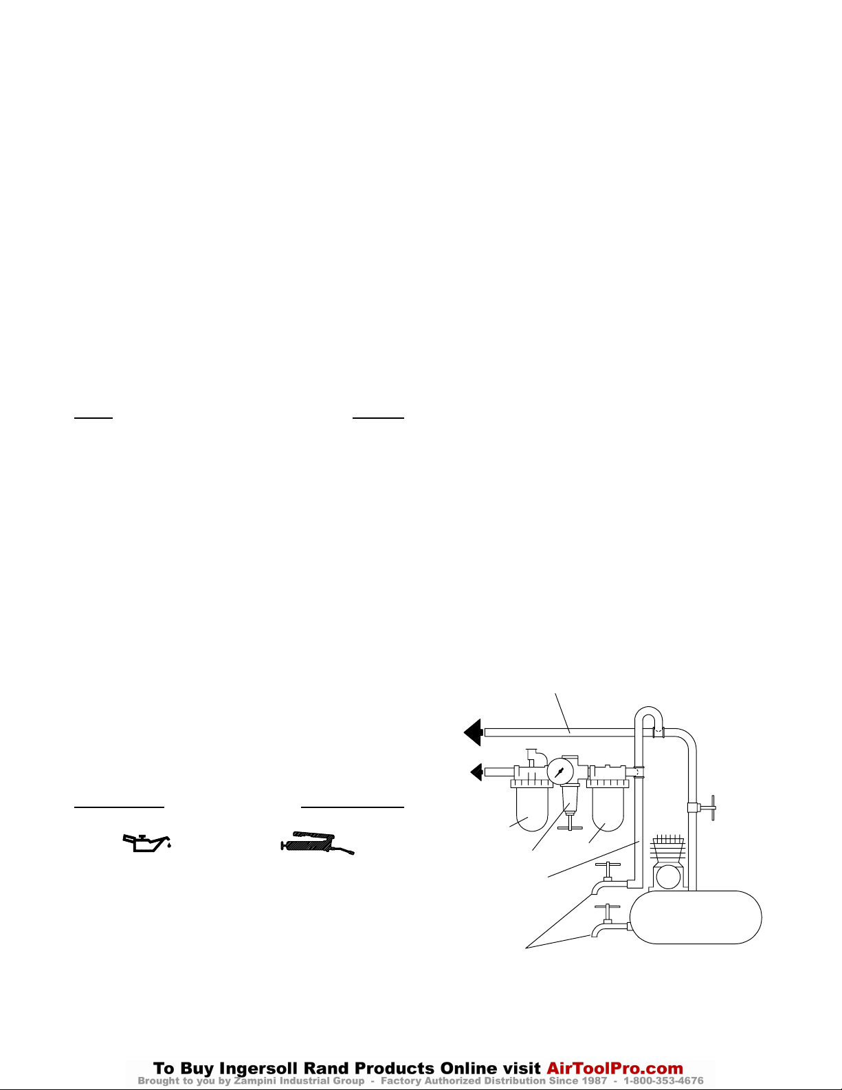
LINHAS PRINCIPAIS 3 VEZES O TAMANHO DA
ENTRADA DA FERRAMENTA PNEUMÁTICA
PARA
SISTEMA DE AR
PARA
FERRAMENTA
PNEUMÁTICA
Ingersoll–Rand No. 50 Ingersoll–Rand No. 28
Use sempre um lubrificador de ar de linha com estas
ferramentas. Nós recomendamos a seguinte Unidade
Filtro–Lubrificador–Regulador:
E.U.A. – No. C31–06–G00
LUBRIFICADOR
REGULADOR
LINHA RAMIFICADA
2 VEZES O TAMANHO
DA ENTRADA DA
FERRAMENTA
PNEUMÁTICA
15
FILTRO
COMPRESSOR
DRENE
REGULARMENTE
(Desenho TPD905–1)
Page 16

COLOCANDO A FERRAMENTA EM FUNCIONAMENTO
INFORMAÇÃO DO
CONTROLADOR
ADVERTÊNCIA
Não tente desmontar o controlador.
O controlador é disponível somente como uma unidade e é
garantido por toda a vida útil da ferramenta se a mesma não for
utilizada com abuso.
Antes de montar, inspeccione cuidadosamente o Controlador
para encontrar lascas, defeitos e dentes. Reponha–o por um
novo Conjunto de Controlador se necessário. Teste a
velocidade livre antes de instalar uma lâmina.
LÅMINAS DA SERRA
Remoção
1. Segure as pás da Flange da Lâmina Externa com uma
chave ajustável para ev itar que a Árvore da Lâmina gire.
2. Usando a Chave de Parafuso de Retenção inserida no
Parafuso de Retenção da Flange, desaparafuse e
remova o Parafuso de Retenção da Flange.
3. Remova a Flange da Lâmina Externa da Árvore da
Lâmina.
4. Retraia o Protector de Balanço e retire a Lâmina
através da Base.
Instalação
1. Retraia o Protector de Balanço e insira a Lâmina para
cima através da Base, certifique–se de que os dentes na
Lâmina apontam no sentido no qual a Lâmina irá girar
(sentido horário quando estando de frente para a lateral
da lâmina da ferramenta).
2. Deslize a Lâmina sobre a Árvore da Lâmina seguida
pela Flange da Lâmina Externa. Alinhe as estrias da
Flange com as estrias da Árvore da Lâmina.
3. Aperte o Parafuso de Retenção da Flange na
extremidade da Árvore da Lâmina.
4. Use uma chave ajustável para agarrar as pás da Flange
da Lâmina Externa para manter a Árvore da Lâmina
sem girar. Usando a Chave de Retenção inserida no
Parafuso de Retenção da Flange, aperte o Parafuso com
um torque entre 27 e 34 Nm (20 e 25 pés–lb).
Ajustando a Profundidade do Corte
1. Segure a Alavanca do Regulador com uma das
mãos e desaperte o Manípulo com a outra.
2. Segure a base e eleve o motor e o resguardo pela
Alavanca do Regulador até a profundidade desejada
ser indicada na escala gravada na borda do suporte
indicador de profundidade.
3. Aperte firmemente o Manípulo.
Ajustando o Ângulo de Corte
1. Desaperte o Manípulo de Inclinação
2. Incline o motor e Protector na Base até que o ajuste
desejado seja obtido como mostrado na escala inscrita
na extremidade do Sector de Inclinação Frontal.
3. Aperte o Manípulo de Inclinação
Visando e Serrando
1. Abra a válvula de regulagem de pressão
completamente ao apertar a Alavanca de Regulagem de
Pressão no Punho.
2. Alinhe a marca a ser seguida com a linha gravada na
Base e empurre a serra para diante.
3. Quando o corte for terminado, libere a Válvula de
Pressão e erga a Serra do local onde estiver sendo
efectuado o corte. O Protector de Balanço irá sair
imediatamente do Protector Estacionário para cobrir a
Lâmina da Serra.
ESPECIFICAÇÕES
Modelo Velocidade
Livre
rpm mm pol. Kg. lb.
S80 4 000 210 8 1/4 6,6 14,5
Tamanho do Disco
(diâmetro)
16
Pêso sem
låminas da serra
Page 17
17
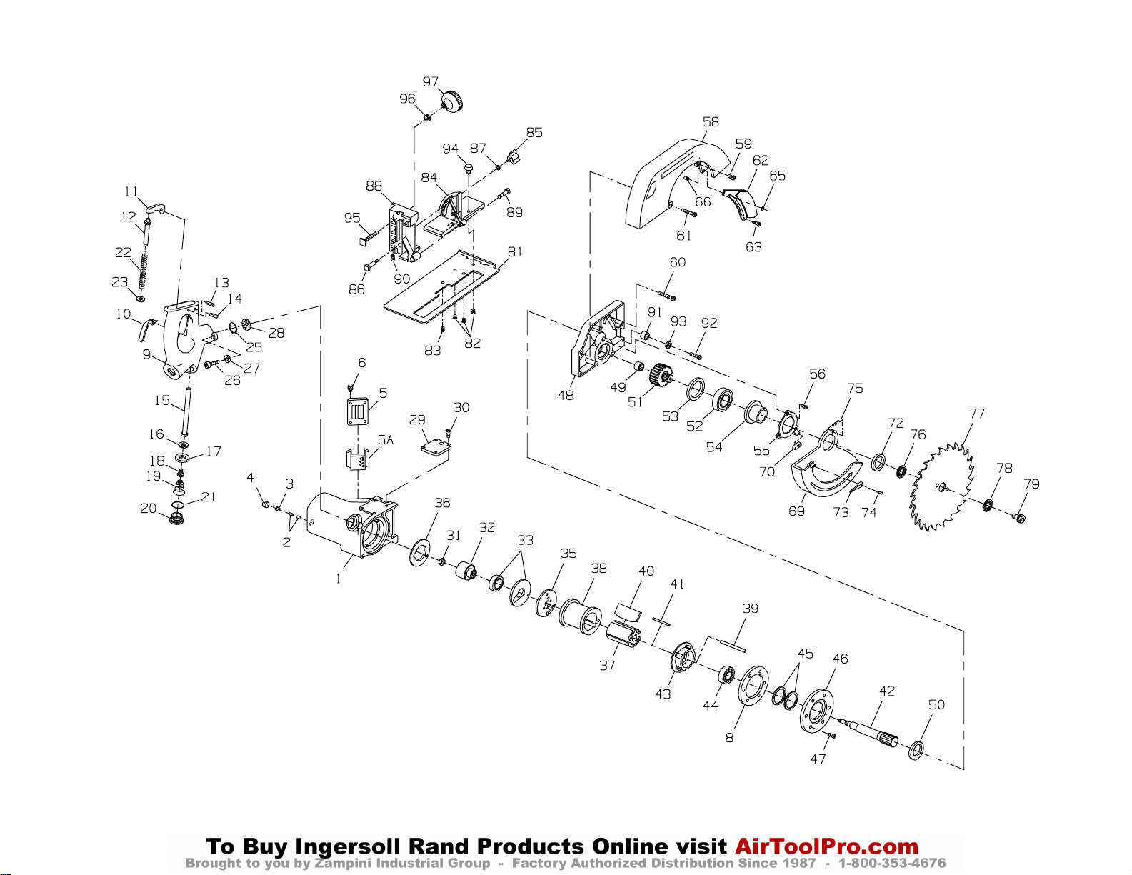
MAINTENANCE SECTION
(Dwg. TPB642–4)
Page 18
18
PART NUMBER FOR ORDERING PART NUMBER FOR ORDERING
1 Motor Housing Assembly ♦• 25 Throttle Handle Seal . . . . . . . . . . . . . . . . . . . . . R4–103
for S80 . . . . . . . . . . . . . . . . . . . . . S80–A40 26 Throttle Handle Cap Screw (2) . . . . . . . . . . . . . 34U–103
for S80–EU . . . . . . . . . . . . . . . . . S80–EU–A40 27 Cap Screw Lock Washer (2) . . . . . . . . . . . . . . . 34U–58
♦• 2 Oiler Felt (2) . . . . . . . . . . . . . . . . . . . . R2–75 ♦• 28 Air Strainer Screen . . . . . . . . . . . . . . . . . . . . . . S120–D02–889
3 Oiler Adjusting Screw . . . . . . . . . . . . . R2–71 29 Nameplate
4 Oiler Plug . . . . . . . . . . . . . . . . . . . . . . . GA57–95 for S80 . . . . . . . . . . . . . . . . . . . . . . . . . . S80–301
5 Exhaust Deflector . . . . . . . . . . . . . . . . S80–23 for S80 –EU . . . . . . . . . . . . . . . . . . . . . . S80–EU–301
5A Exhaust Baffle . . . . . . . . . . . . . . . . . . . S80–124 30 Nameplate Screw (4) . . . . . . . . . . . . . . . . . . . . . S80–MVA008–302
6 Exhaust Deflector Screw (4) . . . . . . . . 99V60–200 31 Controller Retaining Nut . . . . . . . . . . . . . . . . . . 504–639
♦ * Exhaust Silencer . . . . . . . . . . . . . . . . . 2940P–311 32 Controller Assembly . . . . . . . . . . . . . . . . . . . . . S80–A524
* Warning Label 34 Rotor Bearing Seal Assembly (consists
for S80 . . . . . . . . . . . . . . . . . . . . . WARNING–11–99 of Rear Rotor Bearing and Rear Rotor
for S80–EU . . . . . . . . . . . . . . . . . EU–99 Bearing Seal) . . . . . . . . . . . . . . . . . . . . . . . . S80–A28
♦• 8 Motor Housing Gasket . . . . . . . . . . . . . . . . S80–634 • 35 Rear End Plate . . . . . . . . . . . . . . . . . . . . . . . . . . 88V60–12
Throttle Handle Assembly . . . . . . . . . . . . . S12–A400 ♦• 36 Rear End Plate Gasket . . . . . . . . . . . . . . . . . . . . S80–739
9 Throttle Handle . . . . . . . . . . . . . . . . . . S12–400 37 Rotor . . . . . . . . . . . . . . . . . . . . . . . . . . . . . . . . . S80–53
10 Throttle Lever . . . . . . . . . . . . . . . . . . . R4G–93A • 38 Cylinder . . . . . . . . . . . . . . . . . . . . . . . . . . . . . . . 88V60–3
11 Throttle Lever Lock . . . . . . . . . . . . . . . S12–402 ♦• 39 Cylinder Dowel . . . . . . . . . . . . . . . . . . . . . . . . . 88V60–98
12 Throttle Lock Plunger . . . . . . . . . . . . . S12–404 ♦• 40 Vane Packet (set of4 Vanes) . . . . . . . . . . . . . . . . 88V60–42–4
• 13 Throttle Lever Pin . . . . . . . . . . . . . . . . F02–15 ♦• 41 Rotor Key . . . . . . . . . . . . . . . . . . . . . . . . . . . . . . 88V60–70
14 Throttle Lever Lock Pin . . . . . . . . . . . S120–MR–100 42 Rotor Shaft . . . . . . . . . . . . . . . . . . . . . . . . . . . . . S80–204
15 Throttle Valve Stem . . . . . . . . . . . . . . . R4G–161A • 43 Front End Plate . . . . . . . . . . . . . . . . . . . . . . . . . S80–11
♦• 16 Throttle Valve Face . . . . . . . . . . . R4–159A • 44 Front Rotor Bearing . . . . . . . . . . . . . . . . . . . . . . R380–105
♦ă 17 Valve Face Cap . . . . . . . . . . . . . . R4–157 ♦ 45 Motor Clamp Washer (2) . . . . . . . . . . . . . . . . . . 88V60–207
♦ 18 Valve Face Retaining Screw . . . . R4–158 46 Motor Retaining Plate . . . . . . . . . . . . . . . . . . . . S80–55
• 19 Throttle Valve Spring . . . . . . . . . . . . . . R4–262 47 Retaining Plate Screw (6) (1/2”
20 Throttle Valve Cap . . . . . . . . . . . . . . . . R4–266 [13 mm] long) . . . . . . . . . . . . . . . . . . . . . . . . . . 401–638
♦• 21 Throttle Valve Cap Seal . . . . . . . . R4–210 48 Gear Case Assembly . . . . . . . . . . . . . . . . . . . . . S80–A37
22 Plunger Spring . . . . . . . . . . . . . . . . . . . R4H–431 • 49 Blade Arbor Rear Bearing . . . . . . . . . . . . . . H54U–535
23 Plunger Spring Seat . . . . . . . . . . . . . . . S12–675 ♦• 50 Gear Case Seal . . . . . . . . . . . . . . . . . . . . . . . . . . S80–38
* Not illustrated.
♦ Indicates Tune–up Kit part.
• To keep downtime to a minimum, it is desirable to have on hand certain repair parts. We recommend that you stock one (pair or set) of each part indicated
by a bullet (•) for every four tools in service.
MAINTENANCE SECTION
Page 19
19
PART NUMBER FOR ORDERING PART NUMBER FOR ORDERING
51 Blade Arbor . . . . . . . . . . . . . . . . . . . . . . . . . . . 32119 79 Flange Retaining Screw . . . . . . . . . . . . . . . . . . 103405
• 52 Blade Arbor Front Bearing . . . . . . . . . . . . . . . 105352 81 Base . . . . . . . . . . . . . . . . . . . . . . . . . . . . . . . . . 41367–01
53 Arbor Bearing Retainer . . . . . . . . . . . . . . . . . . 19916 82 Base Long Screw (3) . . . . . . . . . . . . . . . . . . . . S80–268
54 Front Arbor Bearing Cage . . . . . . . . . . . . . . . . 23949 83 Base Short Screw . . . . . . . . . . . . . . . . . . . . . . . S80–234
55 Bearing Cage Retainer . . . . . . . . . . . . . . . . . . . 201705 84 Bevel Bracket . . . . . . . . . . . . . . . . . . . . . . . . . 32459
56 Cage Retaining Screw (3) (flat head) . . . . . . . 105588 85 Tilt Knob . . . . . . . . . . . . . . . . . . . . . . . . . . . . . 105094
58 Stationary Guard . . . . . . . . . . . . . . . . . . . . . . . 5898 86 Tilt Knob Screw . . . . . . . . . . . . . . . . . . . . . . . . 105373
59 Guard Short Retaining Screw (2) . . . . . . . . . . FEA100–26 87 Tilt Knob Washer . . . . . . . . . . . . . . . . . . . . . . . 16922
60 Guard Long Retaining Screw Depth Segment Bracket Assembly . . . . . . . . . S80–A571
No. 10–32 x 1–1/2” long . . . . . . . . . 4E–354 88 Depth Bracket . . . . . . . . . . . . . . . . . . . . . . 35253
No. 10–32 x 1–3/8” long . . . . . . . . . S80–313 * Bracket Bushing . . . . . . . . . . . . . . . . . . . . . 104058–1
61 Guard Spring Screw (2) . . . . . . . . . . . . . . . . . . 4E–354 89 Depth Segment Lock . . . . . . . . . . . . . . . . . . . . 105435A
62 Telescoping Guard . . . . . . . . . . . . . . . . . . . . . . 41627 90 Depth Segment Adjusting Screw . . . . . . . . . . . 104024
63 Telescoping Guard Screw . . . . . . . . . . . . . . . . 105560 • 91 Bumper . . . . . . . . . . . . . . . . . . . . . . . . . . . . . . . 105448
* Telescoping Guard Guide . . . . . . . . . . . . . . . . 19906 • 92 Bumper Screw . . . . . . . . . . . . . . . . . . . . . . . . . 104026
65 Guide Retainer . . . . . . . . . . . . . . . . . . . . . . . . . DG10–118 93 Bumper Screw Lock Washer . . . . . . . . . . . . . . 12706
66 Telescoping Guard Guide Pin . . . . . . . . . . . . . 105620–01 94 Rip Fence Knob . . . . . . . . . . . . . . . . . . . . . . . . 104056
* Depth Indicator . . . . . . . . . . . . . . . . . . . . . . . . 27534 95 T–Bolt . . . . . . . . . . . . . . . . . . . . . . . . . . . . . . . 27542
* Indicator Screw . . . . . . . . . . . . . . . . . . . . . . . . WWA100–77 96 T–Bolt Washer . . . . . . . . . . . . . . . . . . . . . . . . . 18985
69 Swing Guard . . . . . . . . . . . . . . . . . . . . . . . . . . 33958 97 Knob . . . . . . . . . . . . . . . . . . . . . . . . . . . . . . . . . 201597
70 Swing Guard Stop . . . . . . . . . . . . . . . . . . . . . . 202724 * Rip Fence . . . . . . . . . . . . . . . . . . . . . . . . . . . . . 30478
* Stop Bracket . . . . . . . . . . . . . . . . . . . . . . . . . . . 202725 * Carrying Case . . . . . . . . . . . . . . . . . . . . . . . . . S80–4
72 Swing Guard Retainer . . . . . . . . . . . . . . . . . . . 19915 * Controller Wrench . . . . . . . . . . . . . . . . . . . . . . 88V60–950
73 Guard Retracting Lever . . . . . . . . . . . . . . . . . . 32434 * Swivel Inlet Assembly . . . . . . . . . . . . . . . . . . . HH1–A165
74 Retracting Lever Screw . . . . . . . . . . . . . . . . . . 104031
• 75 Swing Guard Spring . . . . . . . . . . . . . . . . . . . . . 19598 2, 8, 16, 17, 18, 21, 25, 28, 36, 39, 40,
76 Inner Blade Flange . . . . . . . . . . . . . . . . . . . . . . 27535 41, 45, 50 and non–illustrated part
77 Blade (combination chisel tooth) . . . . . . . . . . 23111–82 Exhaust Silencer 2940P–311) . . . . . . . . . . . . . S80–TK1
78 Outer Blade Flange . . . . . . . . . . . . . . . . . . . . . 205556
* Tune–up Kit (includes illustrated parts
MAINTENANCE SECTION
* Not illustrated.
• To keep downtime to a minimum, it is desirable to have on hand certain repair parts. We recommend that you stock one (pair or set) of each part indicated by a
bullet (•) for every four tools in service.
Page 20

MAINTENANCE SECTION
Always wear eye protection when operating or
performing maintenance on this tool.
Always turn off the air supply and disconnect the air
supply hose before installing, removing or adjusting
any accessory on this tool, or before performing any
maintenance on this tool.
DISASSEMBLY
General Instructions
1. Do not disassemble the tool any further than
necessary to replace or repair damaged parts.
2. Whenever grasping a tool or part in a vise, always use
leather–covered or copper–covered vise jaws to
protect the surface of the part or tool and help prevent
distortion. This is particularly true of threaded
members and housings.
3. Do not remove any part which is a press fit in or on a
subassembly unless the removal of that part is
necessary for repairs or replacement.
4. Do not disassemble the tool unless you have a
complete set of new gaskets and O–rings for
replacement.
5. Do not press any needle bearing from a part unless
you have a new needle bearing on hand for
installation. Needle bearings are always damaged
during the removal process.
Disassembly of Throttle Handle
1. To gain access to the Throttle Valve Stem (15) or
Throttle Valve Spring (19), remove the Throttle Valve
Cap (20).
3. Remove the Stationary Guard Screws (59 and 60) and
the Telescoping Guard Screw (63) and remove the
Stationary Guard (58) and Telescoping Guard (62).
Removal of the Guard Long Retaining Screws (60)
allows removal of the assembled Motor Housing (1).
4. Remove the Cage Retaining Screws (56), the Cage
Retainer (55) and the Arbor Front Bearing Cage (54),
and withdraw the Arbor Front Bearing (52).
5. Remove the Arbor Bearing Retainer (53) and
withdraw the Blade Arbor (51) from the Gear Case
(48).
6. Press the Blade Arbor Rear Bearing (49) from the
Gear Case.
Disassembly of Motor
1. Remove the Retaining Plate Screws (47) and
withdraw the Retaining Plate (46) and assembled
motor from the Motor Housing (1).
2. Remove the Front End Plate (43), Front Rotor
Bearing (44) and Cylinder (38) by grasping the
Cylinder and tapping the splined end of the Rotor
Shaft (42) with a plastic–faced hammer.
3. Remove the Vanes (40) and clamp the Rotor (37) in a
vise with the Controller Assembly (32) upward.
4. Remove the right–hand threaded Controller Retaining
Nut (31).
In the following step, Part No. 88V60–950
Controller Wrench must be used to prevent
damage to the Controller.
5. Use the No. 88V60–950 wrench to remove the
Controller from the Rotor Shaft.
6. Remove the Rotor Bearing Seal Assembly (34) and
Rear End Plate (35) from the Rotor Shaft.
In the following step, the Throttle Lock Plunger
(12), Plunger Spring (22) and Plunger Spring Seat
(23) are free to fall from the Handle (9) after the
Lever Lock (11) is removed.
2. Remove the Throttle Lever (10) by pressing the
Throttle Lever Pin (13) from the Handle, and remove
the Throttle Lever Lock by pressing the Lever Lock
Pin (14) from the Handle.
Removal of Guards and Disassembly of Gearing
1. Remove the Flange Retaining Screw (79), Outer
Blade Flange (78), Blade (77) and Inner Blade Flange
(76).
2. Remove the Swing Guard (69) by disengaging the
tang on the Swing Guard Spring (75), removing the
Swing Guard Retainer (72) and withdrawing the
Guard.
ASSEMBLY
General Instructions
1. Always press on the inner ring of a ball–type bearing
when installing the bearing on a shaft.
2. Always press on the outer ring of a ball–type bearing
when pressing the bearing into a bearing recess.
3. Always use leather–covered or copper–covered vise
jaws. Take extra care not to damage threads or distort
housings.
4. Always clean every part and wipe every part with a
thin film of the recommended oil before installation.
5. Check every bearing for roughness. If an open bearing
must be cleaned, wash it thoroughly in a clean,
suitable, cleaning solution and dry with a clean cloth.
Sealed or shielded bearings should not be cleaned.
Work the recommended grease into every open
bearing before installation.
20
Page 21
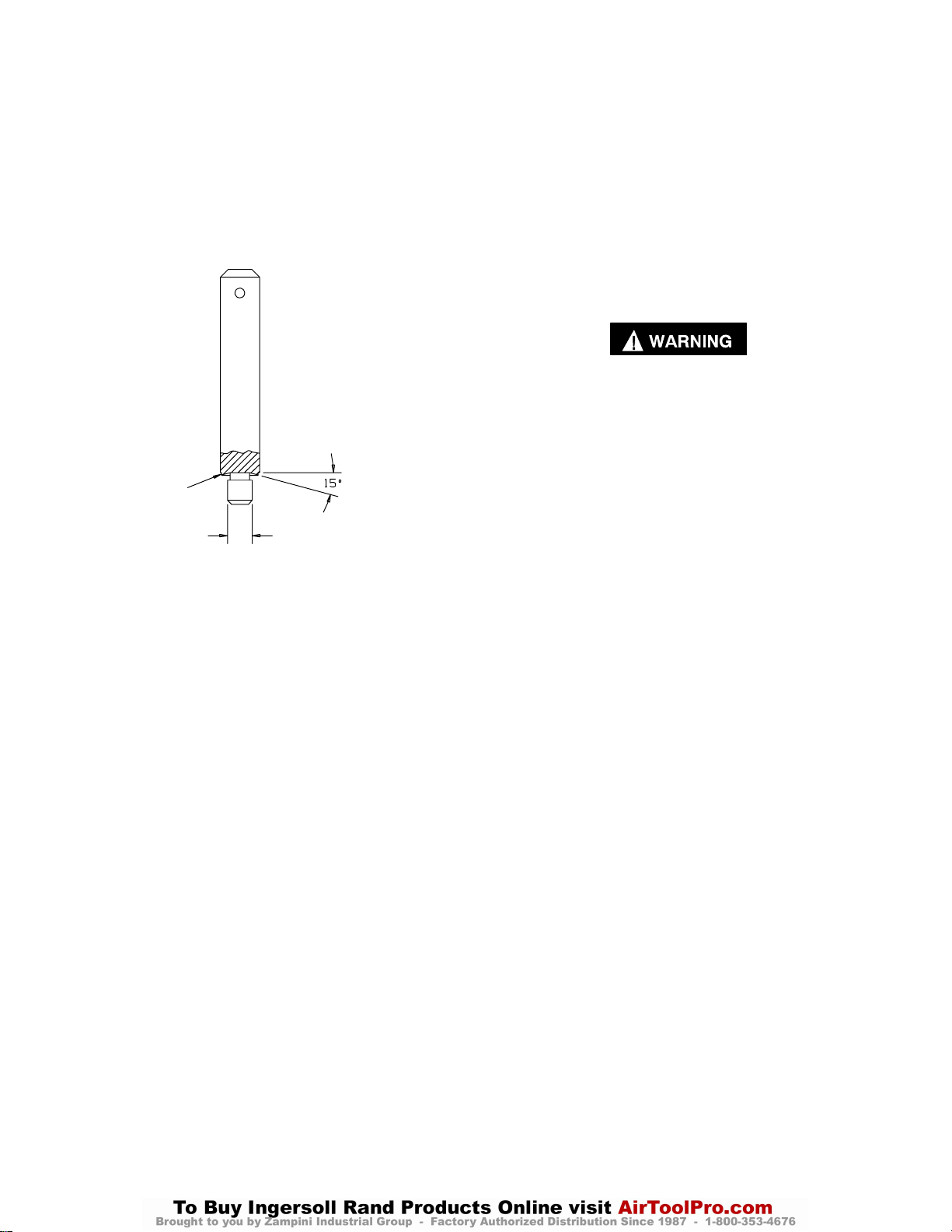
MAINTENANCE SECTION
6. Apply a film of o–ring lubricant to every O–ring
before installation.
7. Unless otherwise noted, always press on the stamped
end of a needle bearing when installing a needle
bearing in a recess. Use a bearing inserting tool
similar to that shown in Dwg. TPD786.
Needle Bearing Inserting Tool
SHOULDER TO
REGULA TE DEPTH
PILOT TO FIT I.D. OF
BEARING.
LENGTH OF PILOT TO BE
APPROXIMATELY 1/8”
LESS THAN LENGTH OF
BEARING
(Dwg. TPD786)
Assembly of the Motor
1. Using an arbor press against the inner race of the
bearing, install the Front Rotor Bearing (44) onto the
Rotor Shaft (42).
2. Inspect the Front End Plate (43) for nicks or burrs. If
replacement is necessary, wipe the part with
Ingersoll–Rand No. 50 Oil. Press the arbor bearing
into the Front End Plate.
3. Hold the Rotor Shaft in a vise, small diameter up.
Insert the Rotor Key (41) in the slot of the Rotor (37).
The Rotor has a staked keyway on one end. Place that
end down over the Arbor. Apply a light film of
Ingersoll–Rand No. 50 Oil to each Vane (40) and
insert one vane, straight edge out, into each slot in the
Rotor. If any new vanes are required, replace the
entire set.
4. Place the Cylinder (38) over the Rotor matching the
cylinder dowel hole to the alignment hole in the Front
End Plate, with the kidney port to the left of the
dowel hole.
5. Apply the Rear End Plate (35) with the kidney port to
the left of the dowel hole.
6. Check the outside diameter and large inside diameter
of the Rotor Bearing Seal (34) for wear. If the outside
diameter is worn to 1.1764” or smaller, and/or the
large inside diameter is worn to 0.9103” or larger,
install a new Rotor Bearing Seal. Take all
measurements 30 degrees to the right of the dowel
hole when facing the hub side of the Seal. Install the
Rotor Bearing Seal hub down.
7. Press the Rear Rotor Bearing onto the hub of the
Controller (32).
8. Slip the Controller Assembly over the arbor. Rotate
the Controller counterclockwise since this is a
left–hand thread.
Use only the special 88V60–950 Controller Wrench
for applying the assembly. Tighten the Controller
between 14 and 16 ft–lb (19.0 and 21.7 Nm) torque.
Do not exceed 16 ft–lb (21.7 Nm). The Controller
may be damaged if this torque is exceeded. Always
check the free speed of a Saw after it has been
reassembled and before it is put back into service.
Refer to the TEST AND INSPECTION
PROCEDURE on Page 11. Never use a Saw which
runs in excess of the maximum speed listed in the
TEST AND INSPECTION PROCEDURE.
9. Install the Controller Retaining Nut (31) and tighten it
between 5 and 7 ft–lb (6.8 and 9.5 Nm) torque.
10. Place the Motor Housing (1) in a vise, open end up.
Lightly dampen the Rear End Plate Gasket (36) with
oil and line it up with the hole in the Motor Housing
so that the notch in the Gasket matches the Motor
Housing.
11. With an assembly dowel, line up the motor in the
Motor Housing. Remove the assembly dowel and
insert the Cylinder Dowel (39).
12. Install the two Motor Clamp Washers (45) concave
(dished) side up.
13. Apply the Motor Retaining Plate (46) and the six
Screws (47). Slightly tighten opposite Screws, make
sure the arbor is free, then tighten all Screws to
14 ft–lb (19 Nm) torque.
14. Again make certain the Rotor Shaft is free.
15. Fill the oil chamber with the recommended oil and
insert the Oiler Plug (4). Tighten the Plug to 4 ft–lb
(5.4 Nm) torque.
Assembly of Gearing and Installation of Guards
1. Using a bearing inserting tool as shown in Drawing
TPD786, insert the Blade Arbor Rear Bearing (49)
into the bore of the Gear Case (48).
2. Insert the Blade Arbor (51), large diameter first, into
the large bore end of the Gear Case and retain it using
the Arbor Bearing Retainer (53).
21
Page 22

MAINTENANCE SECTION
3. Press the Blade Arbor Front Bearing (52) onto the
Arbor, slide the Front Arbor Bearing Cage (54) over
the Bearing and retain it using the Bearing Cage
Retainer (55) and Cage Retaining Screws (56).
Tighten the Screws to 20 in–lb (2.3 Nm) torque.
4. Install the Stationary Guard (58) using the Guard
Retaining Screws (59 and 60). Tighten the Screws to
3 ft–lb (4.1 Nm) torque.
5. If the Telescoping Guard (62) was removed, engage
the slot in the Guard with the Guide Pin (66) and
retain the Guard using the Guide Retainer (65).
6. Install the Guard Retracting Lever (73) onto the
Swing Guard (69) using the Lever Screw (74).
Tighten the Lever Screw to 8 in–lb (1.0 Nm) torque.
7. Slide the Swing Guard onto the hub of the Bearing
Cage, attach one end of the Swing Guard Spring (75)
to the hole in the edge of the Swing Guard and secure
the free end of the Spring using the Guard Spring
Screw (61).
8. Slide the Swing Guard Stop (70) onto the Swing
Guard Bracket. With the air supply shut off and the
hose drained or with the air hose disconnected,
operate the Swing Guard manually several times to
see that it swings quickly into the closed position.
Assembly of Throttle Handle
1. Retain the Throttle Valve Face (16) on the Throttle
Valve Stem (15) using the Valve Face Cap (17) and
the Valve Face Retaining Screw (18).
2. Install the Throttle Valve Cap Seal (21) onto the
Throttle Valve Cap (20).
3. Insert the assembled Valve Stem, followed by the
Throttle Valve Spring (19), small diameter first, into
the bore of the Throttle Handle (9). Retain these parts
using the Throttle Valve Cap.
4. Install the Throttle Lever (10) into its slot in the
Throttle Handle as illustrated on Drawing TPB642–3
using the Throttle Lever Pin (13).
5. Drop the Plunger Spring Seat (23) into the Throttle
Handle and insert the Throttle Lock Plunger (12) and
Plunger Spring (22) into the plunger hole in the
Handle. Make certain the Plunger enters the hole in
the center of the Seat.
6. Engage the recess in the face of the Throttle Lever
Lock (11) with the exposed end of the Lock Plunger,
align the through hole in the Throttle Handle with the
hole in the Lever Lock and press the Throttle Lever
Lock Pin (14) into the Handle. Actuate the Lever
Lock and Lever to determine that they are operating
smoothly.
7. Before installing the assembled Handle onto the
Motor Housing (1), install an air hose in the tapped
inlet, apply 90 psig (6.2 bar/620 kPa) air pressure to
the Handle and operate the Lock and Lever a number
of times. Make certain that no air passes through the
valve when the Handle is in the locked position.
8. Position the Throttle Handle Assembly on the Motor
Housing and secure it by installing the Throttle
Handle Cap Screws (26) and Lock Washers (27).
TEST AND INSPECTION PROCEDURE
Run the performance tests at 90 psig (6.2 bar/620 kPa) air
pressure at the inlet of the tool with an eight foot (2.44 m)
length of 3/4” (19 mm) diameter air supply hose.
1. Without a blade on the tool, operate the Saw with the
Throttle Lever fully depressed and check the free
speed by applying a hand–held tachometer to the
spindle end. The minimum allowable free speed is
3 850 rpm; the maximum allowable free speed is
4 150 rpm.
2. Test the Saw for power by operating the motor on a
0.0003 brake with a 2–1/4 lb (10.0 N) load. The speed
of the Saw must be 2 500 rpm when operated under
these conditions. Continue this test to determine a
minimum stall force of 5 lb (22 N).
3. There must be no objectionable leaks in any
non–exhaust area. The Throttle must not leak when it
is closed.
4. There must be no leaks past the closed Throttle that
will run the motor.
5. The Saw must start smoothly when the Throttle Lever
is depressed and must shut off completely when the
Throttle Lever is released.
6. The Saw must be equipped with a spring–loaded Lock
(11). The Lock must return to the locked position
when the Throttle Lever is released and must prevent
operation of the Saw until the Lock is released.
7. The tool must run smoothly without noticeable
vibration or unusual sound.
DISCONNECT THE SAW FROM THE AIR
SUPPLY HOSE OR SHUT OFF AIR TO THE
TOOL BEFORE PROCEEDING WITH THE
TEST AND INSPECTION PROCEDURE.
8. The Arbor (51) must turn freely with no evidence of
brinnelled bearings.
9. The splines on the arbor must be free of nicks and
damage.
10. The Nameplate must be legible, in place and securely
fastened. Make replacement if necessary.
22
Page 23

MAINTENANCE SECTION
TROUBLESHOOTING GUIDE
Trouble Probable Cause Solution
Loss of power or low free speed Low air pressure Check the air supply. For top performance, the air
pressure must be 90 psig (6.2 bar/620 kPa) at the
inlet of the tool.
Clogged Air Strainer Screen Clean the Air Strainer. Screen in a clean, suitable,
cleaning solution. If cannot be cleaned, replace it.
Worn or broken Vanes Replace the complete set of Vanes.
Worn or broken Cylinder Replace the Cylinder if it is cracked or if the bore
appears wavy or scored.
Improper lubrication or dirt
build–up
Rough operation Worn or broken Rear or
Front Rotor Bearing
Worn Rotor Key Replace the Key. Check the Rotor Shaft and Rotor
Scoring Improper assembly Make certain that all motor parts are properly
Rotor Bearing Seal misalignment Loosen the Retaining Plate screws and rotate the
Air leaks Worn Valve Face Replace worn parts.
Worn Motor Housing Gasket Replace the Gasket.
Oiler Plug not tight Tighten the Oiler Plug.
Distorted face on Motor housing. Polish lightly using fine emery cloth on a flat
Clean the motor unit parts and lubricate as
instructed.
Examine each Bearing. Replace if worn or
damaged.
for key slot wear and replace if necessary.
aligned prior to clamping the motor assembly.
spindle by hand to align the Seal. Tighten the
Screws. The Rotor Shaft must rotate freely.
metal plate to remove high spots. If the tool has
been dropped and the Motor Housing is damaged,
replace with a new Motor Housing Assembly.
SAVE THESE INSTRUCTIONS. DO NOT DESTROY.
23
 Loading...