

Ingersoll-Rand LCA060DIP3LRU, LCA080DIP3LRE-E, LCA120DIP3LRE-E, LCA030SIP3LRU-E, LCA250QIP3LRN-E User Manual
...Page 1

1
WARNING
PARTS AND MAINTENANCE
MANUAL
For
AIR HOIST WITH TROLLEY
LC2A015SIP3LVU..-E & LC2A030DIP3LVU..-E
LC2A015SIP3LVU..& LC2A030DIP3LVU..
LCA030SIP3LRU..-E / LCA060DIP3LRU..-E
LCA060DIP2LGU..-E / LCA070DIP3LRU..-E
LCA080DIP3LRE..-E
LCA060SIP3LRE..-E / LCA060SIP3LRN..-E
LCA120DIP3LRE..-E / LCA120DIP3LRN..-E
LCA250QIP3LRE..-E / LCA250QIP3LRN..-E
READ THIS MANUAL BEFORE USING THESE PRODUCTS. This manual contains important
safety, installation, operation information. Make this manual available to all persons responsible for
the operation, installation of these products.
Do not use this hoist for lifting, supporting, or transporting people or lifting or supporting loads over
people.
Always operate, inspect and maintain this hoist in accordance with European or National Standards
Safety Code and any other applicable safety codes and regulations.
Refer all communications to the nearest Ingersoll-Rand Material Handling Products Office or
Distributor.
Form SAM 0206
Edition 17
September 2011
2002 IR/SAMIIA
Page 2

2
TABLE OF CONTENTS
DESCRIPTION PAGE NO.
Safety Information
Danger, Warning, Caution and Notice ............................................................................................................3
Safety, Summary .............................................................................................................................................3
Safe Operating Instructions .............................................................................................................................4
Installation
Mounting .........................................................................................................................................................5
Air system .......................................................................................................................................................5
Motor ..............................................................................................................................................................5-6
Chain container ...............................................................................................................................................6
Storing the hoist ..............................................................................................................................................6
Adjustment trolley (LCA015SIP3LVU/030DIP3LVU) .............................................................................6
Adjustment trolley (LCA030SIP3LR/060DIP3LR/070DIP3LR) ...............................................................7
Adjustment trolley (LCA060SIP3LR TO LCA250QIP3LR) .....................................................................8
Specifications (LC2A015SIP3LVU/030DIP3LVU) ...................................................................................9
Specifications (LCA030SIP3LR/060DIP3LR) ...........................................................................................10
Specifications (LCA035SIP3LR/070DIP3LR) ...........................................................................................11
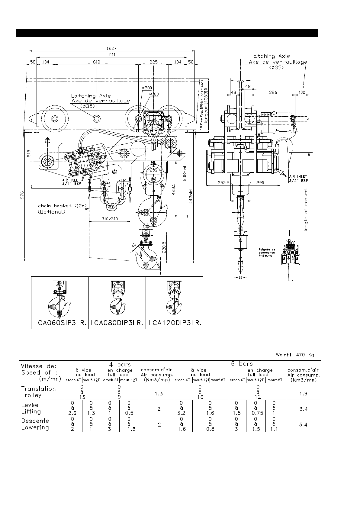
Specifications (LCA060SIP3LR/LCA080DIP3LR/120DIP3LR) ...............................................................12
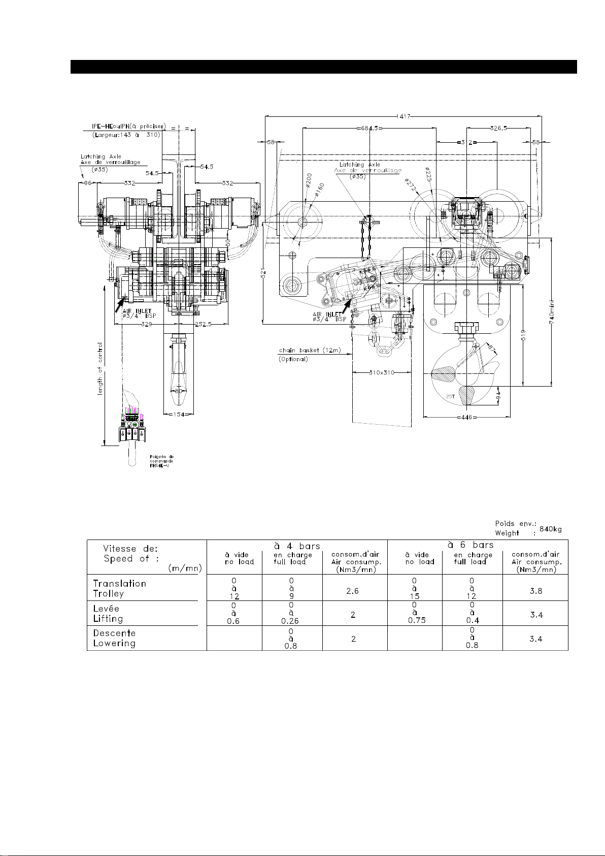
Specifications (LCA250QIP3LR) ...............................................................................................................13
Pneumatique scheme (LC2A015SIP3LVU/030DIP3LVU) .........................................................................14
Pneumatique scheme (LCA030SIP3LR TO LCA250QIP3LR) ....................................................................15
Operation .......................................................................................................................................................16
Inspection .......................................................................................................................................................17-18
Lubrication ....................................................................................................................................................19
Maintenance .................................................................................................................................................20-21-22-23
Parts
Air Chain Hoist Assembly Drawing (LC2A015SIP3LVU/030DIP3LVU)...................................................24
Air Chain Hoist Assembly Parts List (LC2A015SIP3LVU/030DIP3LVU)...................................................25-26
Air Chain Hoist Assembly Drawing (LCA030SIP3LR/060DIP3LR/070DIP3LR)................................ .....27-28
Air Chain Hoist Assembly Parts List (LCA030SIP3LR/060DIP3LR/070DIP3LR).....................................29-30
Air Chain Hoist Assembly Drawing (LCA060SIP3LR/120DIP3LR)..........................................................31 -32
Air Chain Hoist Assembly Parts List (LCA060SIP3LR/120DIP3LR)................................................. .........33-34
Air Chain Hoist Assembly Drawing (LCA250QIP3LR) )................................ ...........................................35-36
Air Chain Hoist Assembly Parts List (LCA250QIP3LR)................................ .............................................37-38
LIFTCHAIN air hoist for all models (for LC2A015S & LC2A30D) ................................ Refer to manual MHD56297
2HP SU Assembly Drawing and Parts List (for LC2A015S & LC2A30D) ...................... Refer to manual MHD56297
4HP SU Assembly Drawing and Parts List (for LC2A015S & LC2A30D) ...................... Refer to manual MHD56297
LIFTCHAIN air hoist for all models (for LCA030S to LCA250Q) .................................. Refer to manual SAM0208
2HP SU Assembly Drawing and Parts List (for LCA030S to LCA250Q) ........................ Refer to manual SAM0208
4HP SU Assembly Drawing and Parts List (for LCA030S to LCA250Q) ........................ Refer to manual SAM0208
Pneumatic Motor & Reducer Assembly Drawing (LC2A015S/030D) ...........................................................39
Pneumatic Motor & Reducer Assembly Parts list.(LC2A015S/030D).................................... .......................40
Warning: Motor Assembly for LC2A015S/LC2A030DIP3LVU…-E ............................................................41
Connection accessories Assembly Drawing and Parts List .............................................................................42
Single and double fall bottom Hook Assembly Drawing (LC2A015S to 060D) ............................................43
Single and double fall bottom Hook Parts List (LC2A015S to 060D) ............................................................44
Bottom Hook Assembly Drawing and Parts List (LCA060S).................................... .....................................45
Bottom Hook Assembly Drawing and Parts List (LCA070D).................................... ....................................46
Bottom Hook Assembly Drawing and Parts List (LCA080D).................................... ....................................47
Bottom Hook Assembly Drawing and Parts List (LCA120D).................................... ....................................48
Bottom Hook Assembly Drawing and Parts List (LCA250Q).................................... ....................................49
Chain Container Assembly Drawing & Parts List LCA2015S/030D Option B .............................................50-51
Chain Container Assembly Drawing & Parts List LCA2015S/030D Option B .............................................52
Chain Container Assembly Drawing & Parts List LCA030S/060D/070D ....................................................53
Chain Container Assembly Drawing & Parts List LCA060S to 250q ............................................................54
Chain Container Assembly Drawing & Parts List LCA0180T/250Q .............................................................55
PHS2E-PHS4E Pendant Control ........................................................................................ Refer to manual SAM0139
Rope Control Assembly Drawing & Parts List LCA030S/060D/070D .........................................................56
Part ordering information ............................................................................................................................57
Guarantee ......................................................................................................................................................58
Important notice............................................................................................................................................59
Page 3

3
SAFETY INFORMATION
DANGER
WARNING
CAUTION
NOTICE
WARNING
NOTICE
This manual provides important information for all
personnel involved with the safe installation, operation and
proper maintenance of this product. Even if you feel you
are familiar with this or similar equipment, you should read
and understand this manual before operating the product.
Danger, Warning, Caution and Notice
Throughout this manual there are steps and procedures
which, if not followed, may result in injury. The following
signal words are used to identify the level of potential
hazard.
Danger is used to indicate the
presence of a hazard which willcause
severe injury, death, or substantial
property damage if the warning is
ignored.
Warning is used to indicate the
presence of a hazard which can cause
severe injury, death, or substantial
property damage if the warning is
ignored.
Caution is used to indicate the
presence of a hazard whichwill or can
cause minor injury or property damage
if the warning is ignored.
Notice is used to notify people of
installation, operation or maintenance
information which is important but not
hazard-related.
Safety Summary
The National Safety Council, Accident Prevention
Manual for Industrial Operations, Eighth Edition and
other recognized safety sources make a common point.
Employees who work near cranes or assist in hooking on or
arranging a load should be instructed to keep out from
under the load. From a safety standpoint, one factor is
paramount : conduct all lifting operations in such a manner
that if there were an equipment failure, no personnel would
be injured. This means keep out from under a raised load
and keep out of the line of force of any load.
To our interpretation, INGERSOLL-RAND Material
Handling hoists are manufactured in accordance with the
latest standards.
However, contrary to common belief, as we understand it,
generally places the burden of compliance with the user,
not the manufacturer. Many requirements are not concerned
or connected with the manufactured product but are, rather,
connected with the final installation. It is the owner's
responsibility and user's responsibility to determine the
suitability of a product for any particular use. Check all
applicable industry, trade association, federal, state and
local regulations. Read all operating instructions and
warnings before operation.
Rigging : It is the responsibility of the operator to exercise
caution, use common sense and be familiar with proper
rigging techniques.
INGERSOLL-RAND Replacement Parts are
specifically designed to ensure optimum performance
of your equipment. Use of other than genuine
INGERSOLL-RAND Material Handling parts may
adversely affect safe operation and will invalidate the
warranty.
Do not use this hoist or attached equipment for
lifting, supporting, or transporting people or
supporting loads over people.
The supporting structures and load-attaching devices
used in conjunction with this hoist must provide and
adequate safety factor to handle the rated load, plus
the weight of the hoist and attached equipment. This
is the customer's responsibility. If in doubt, consult a
qualified structural engineer.
Page 4

4
SAFE OPERATING INSTRUCTIONS
The following warnings and operating instructions are
intended to avoid unsafe operating practices which might
lead to indury or property damage.
INGERSOLL-RAND recognizes that most companies
who use hoists and trolley safety program in force at their
facility. In the event that some conflict exists between a
rule set forth in this publication and a similar rule already
set by an individual company, the more stringent of the
two should take precedence.
Safe Operating Instructions are provided to make an
operator aware of dangerous practices to avoid and are
not necessarily limited to the following list. Refer to
specific sections in the manual for additional safety
information.
Refer to the hoist manual for additional precautions and
instructions.
1. Only allow qualified people (trained in safety and
operation) to operate the hoist.
2. Only operate a hoist and a trolley if you are
physically fit to do so.
3. When a "DO NOT OPERATE" sign is placed on the
hoist controls, do not operate the hoist until the sign
has been removed by designated personnel.
4. Before each shift, the operator should inspect the
hoist and the trolley for wear or damage.
5. Never use a hoist and a trolley that inspection
indicates is defective.
6. Periodically, inspect the hoist and the trolley
thoroughly and replace worn or damaged parts.
7. Lubricate the hoist and the trolley regularly.
8. Using the hoist, only lift loads less than or equal to
the lower rated capacity of the trolley or hoist.
9. Only attach a hoist having a raded capacity equal to
or less than the capacity of the trolley.
10. When using two hoists to suspend one load, select
two trolleys each having a rated capacity equal to or
more than the load. This provides adequate safety in
the event of a sudden load shift or failure of one
trolley.
11. Never place your hand inside the throat area of a
hook
12. Only operate a hoist when the load is centered under
the hoist. Do not "side pull" or "yard".
13. Pay attention to the load at all times when operating
the trolley.
14. Make sure all people are clear of the load path. Do
not lift a load over people.
15. Never use the hoist for lifting or lowering people,
and never allow anyone to stand on a suspended
load.
16. Do not swing a suspended load.
17. Never suspend a load for an extended period of time
18. Never leave a suspended load unattended.
19. Never weld or cut a load suspended by the trolley.
20. Always rig the load properly and carefully.
21. Remove all loads before performing any
maintenance.
22. Avoid collision or bumping of hoist and trolley.
23. After use, properly secure hoist and all loads.
Page 5

5
INSTALLATION
Prior to installing the hoist, carefully inspect it for possible
shipping damage.
Hoists are supplied fully lubricated from the factory.
Lubrication of the load chain is recommended before initial
hoist operation.
CAUTION
• Owners and users are advised to examine specific,
local or other regulations, including American National
Standards and/or OSHA Regulations which may apply
to a particular type of use of this product before
installing or putting hoist to use.
WARNING
• A falling load can cause injury or death. Before
installing, read "Safety Information."
Mounting
Make certain your hoist is properly installed. A little extra
time and effort in doing so can contribute a lot toward
preventing accidents and helping you get the best service
possible.
Always make certain the supporting member from which
the hoist is suspended is strong enough to support the
weight of the hoist plus the weight of the maximum rated
load plus a generous factor of at least 500% of the
combined weights.
If the hoist is suspended by a top hook, the supporting
member should rest completely within the saddle of the
hook and be centered directly above the hook shank. Do not
use a supporting member that tilts the hoist.
Hook Mounted Hoist
Place hook over mounting structure. Make sure hook latch
is engaged.
Trolley Mounted Hoist
When installing a trolley on a beam, measure the beam
flange and temporarily install the trolley on the hoist to
determine the exact distribution and arrangement of the
spacers. The total distance between the wheel flanges
should be 3/16 in. to 1/4 in. (4.76 mm to 6.35 mm) greater
than the width of the beam flange.
The number of spacers between the trolley side plate and
the mounting lug on the hoist must be the same in all four
locations in order to keep the hoist centered under the Ibeam. The remaining spacers must be equally distributed on
the outside of the side plates. (For additional information
refer to the trolley manufacturer's literature.)
WARNING
• At least one mounting spacer must be used between
the head of each trolley bracket bolt and the trolley
bracket and between each trolley bolt nut and the
trolley bracket. Failure to do this could cause the hoist
to fall when used improperly.
Ensure the trolley bolts or nuts are torqued in accordance
with manufacturer's specifications. When installing the
hoist and trolley on the beam, make certain the side plates
are parallel and vertical. After installation, operate the
trolley over the entire length of the beam with a capacity
load suspended 4 to 6 inches (10 to 15 cms) off the floor.
CAUTION
• To avoid an unbalanced load which may damage the
trolley, the hoist must be centered under the trolley.
NOTICE
• Trolley wheels ride on the top of the lower flange of
the beam.
Air System
The supply air must be clean, lubricated and free from
moisture. A minimum of 90 psi (6.3 bar/630 kPa) at the
hoist motor is required to provide rated hoist capacity. Air
inlet port size for LCA015S and LCA030D units is 1/2 in.
BSP. On all other units the inlet port size is 3/4 in. BSP.
Air Lines
The inside diameter of the hoist air supply lines must not be
smaller than 3/4 in. (19 mm). Before making final
connections, all air supply lines should be purged before
connecting to system inlet. Supply lines should be as short
and straight as installation conditions will permit. Long
transmission lines and excessive use of fittings, elbows,
tees, globe valves, etc. cause a reduction in pressure due to
restrictions and surface friction in the lines.
Lubricator
The air motor may be operated without lubrication. If an air
line lubricator is used, it should be replenished daily with
SAE 30W Grade ISO VG 100 oil (minimum viscosity 135
Cst at 104° F (40° C)).
CAUTION
• Shut off air supply before filling air line lubricator.
Filter
It is recommended that an air line strainer/filter be installed
within 3 ft (1 m) of the motor air inlet port to prevent dirt
from entering the motor. The strainer/filter should provide
20 micron filtration and include a moisture trap. Clean the
strainer/filter monthly to retain its operating efficiency.
Moisture in Air Lines
Moisture that reaches the air motor through the supply lines
is the chief factor in determining the length of time between
service overhauls. Moisture traps can help eliminate
moisture. Other methods, such as an air receiver which
collects moisture before it reaches the motor or an
aftercooler at the compressor that cools the air prior to
distribution through the supply lines are also helpful.
Motor
For optimum performance and maximum durability of
parts, operate the air motor within the operating
specifications provided in the "SPECIFICATIONS"
section. The air motor should be installed as near as
possible to the compressor or air receiver.
Page 6

6
Overload Device
NOTICE
Overload protection is integrated into the motor body and is
standard on -E versions. The overload system is based on
detection of the difference in air pressure between the inlet
and outlet ports. It consists of a valve which is normally
closed. The valve senses pressure at the motor inlet and
outlet and compares the difference between the two
pressures to the index value established by spring
adjustment. A difference in pressure greater than the index
value causes the emergency stop to be activated. This then
exhausts the air and hoist operation stops.
Overload protection is adjusted at the factory to 120% of
the safe working load (SWL). It is also able to operate on
both sides for mining versions with two bottom hooks.
Refer to the "MAINTENANCE" section for adjustment
procedures.
Main Air Shut-off Valve
The main air shut-off valve is completely integrated into the
motor body and is standard on -E versions.
Chain container
1. Check the chain container size to make sure the length of
the load chain is within the capacity of the chain container.
Replace with a larger chain container if required.
2. When a chain bucket is used, Install a chain buffer on the
15th link from the end of the chain.
3. Attach the chain container to the hoist.
4. Run bottom block to the lowest point and run hoist in the
"UP" direction to feed the chain back into the container.
NOTICE
• Allow chain to pile naturally in the chain container.
Piling the chain carelessly into the container by hand
may lead to kinking or twisting that will jam the hoist.
Attaching Limit Stop
1. On hoists without a chain bucket, slide buffer and washer
onto chain.
2. Install limit stop as described under "Chain Container".
3. Run hoist slowly in the "DOWN" direction to verify limit
stop activates cutout.
Storing the Hoist
1. Always store the hoist in a no load condition.
2. Wipe off all dirt and water.
3. Oil the chain, hook pins and hook latch.
4. Place in a dry location.
5. Plug hoist air inlet port.
6. Before returning hoist to service, follow instructions for
hoists not in regular service in the "INSPECTION" section.
ADJUSTMENT TROLLEY LCA015S/LCA030D
Pre-adjust trolley for installation using Dwg. D5230233 and the
following instructions.
1. Fasten tightening nuts (74) to one end of suspension shaft (75),
using springwashers (73) , apply Loctite® 243 to capscrews
threads.
2. Measure beam flange width and establish required position for
spacers. Install required outside spacers on suspension shaft (75).
3. Thread a nut (66) onto each end of the screw rod (67), as far to
the center as possible.
4. Insert one end of this rod into the side plate and loosely fasten
with another nut (66).
5. Insert suspension shaft through side plate (36).
6. Install an equal number of spacers to each side of hoist
support (35), and sprokets wheels support (58), on suspension
shaft.
• The total clearance between the beam and the trolley wheel
flanges is 4 to 8 mm when trolley is installed correctly. As
shown in Dwg. D5230233, the difference between dimensions
“X” and “Y” equals the total clearance.
7. Support the assembled portion of trolley on the beam.
8. Install second side plate (37).
9. Place the rest of spacers on the suspension shaft and secure
loosely with nutsand springwashers.
10. Verify trolley wheel to beam total clearance. Adjust spacer
locations until clearance specification is attained (refer to Dwg.
D5230233). Apply Loctite® 243 to nuts and secure in place.
11. Screw inner nuts (66) out until they contact with side plates.
Thread outside nuts (66) onto screw or until tight against side
plates. Check that side plates are perpendicular to beam.
12. Upon completion of installation, ensure trolley beam stops are
installed and conduct initial operating checks as described in
“OPERATION” section. Check that side plates are vertical and
parallel to each other.
(Dwg.D5230233
Page 7
7
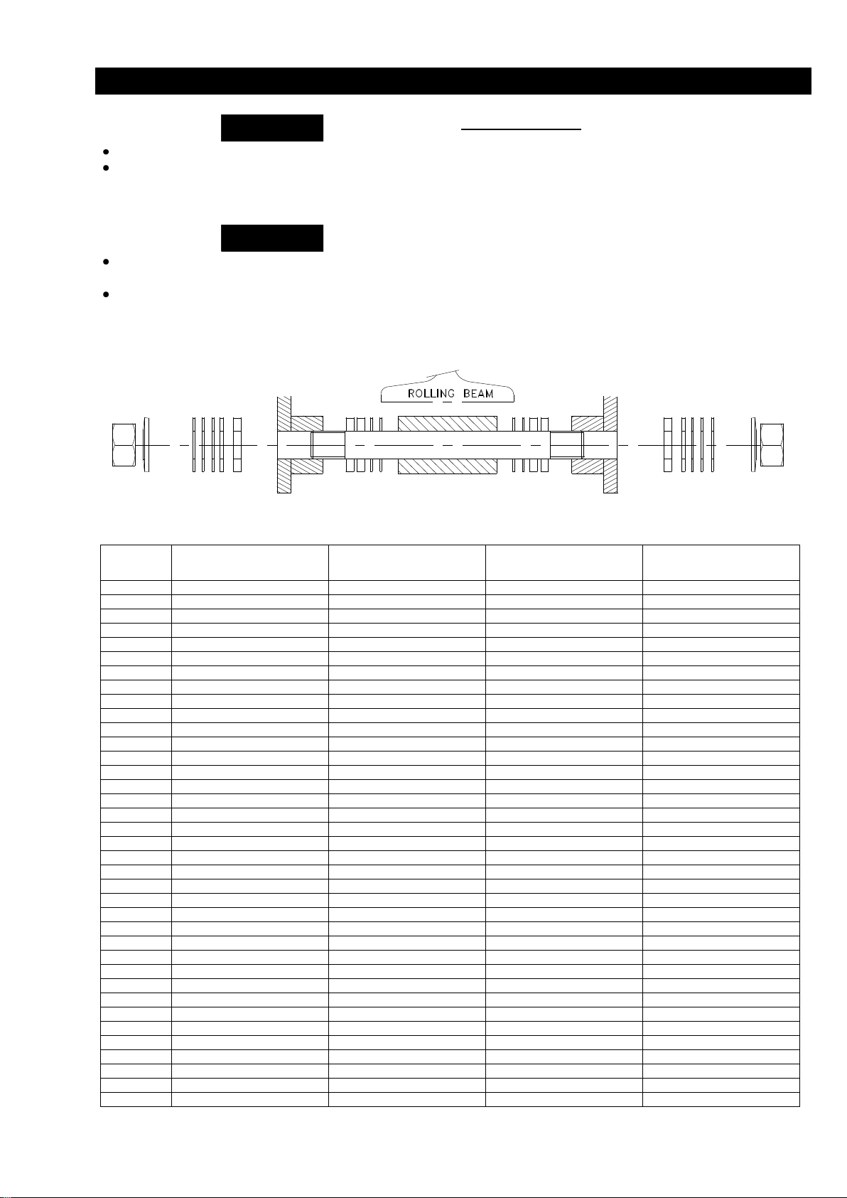
ADJUSTMENT TROLLEY LCA030S/LCA060D/LCA70D
WARNING
NOTICE
Rolling beam
Additionnal thickness
of distance washer
Thickness of
distance washer
Thickness of
distance washer
to make use adjustment
Additionnal thickness
of distance washer
to make use adjustment
IPN 220-98
42.5+25+15+5+4+3.5+3+3+2.5+2.5
0 0 2.5+2.5+3+3+3.5+4+5+15+25+42.5
IPN 240-106
42.5+25+15+5+3.5+3+3+2.5+2.5
4 4 2.5+2.5+3+3+3.5+5+15+25+42.5
IPN 260-113
42.5+25+15+4+3.5+3+3+2.5
2.5+5
5+2.5
2.5+3+3+3.5+4+15+25+42.5
IPN 280-119
42.5+25+15+4+3.5+3+2.5
2.5+3+5
5+3+2.5
2.5+3+3.5+4+15+25+42.5
IPN 300-125
42.5+25+15+4+3+3
2.5+2.5+3.5+5
5+3.5+2.5+2.5
3+3+4+15+25+42.5
IPN 320-131
42.5+25+15+4+3
2.5+2.5+3+3.5+5
5+3.5+3+2.5+2.5
3+4+15+25+42.5
IPN 340-137
42.5+25+15+4
2.5+2.5+3+3+3.5+5
5+3.5+3+3+2.5+2.5
4+15+25+42.5
IPN 360-143
42.5+25+4+3.5+3+3+2.5
2.5+5+15
15+5+2.5
2.5+3.5+4+25+42.5
IPN 400-155
42.5+25+4+3.5+2.5
2.5+3+3+5+15
15+5+3+3+2.5
2.5+3+3+3.5+4+25+42.5
IPN 450-170
42.5+15+4+3+3+2.5
2.5+3.5+5+25
25+5+3.5+2.5
2.5+3+3+4+15+42.5
IPN 500-185
42.5+5+4+3+3+2.5+2.5
3.5+15+25
25+15+3.5
2.5+2.5+3+3+4+5+42.5
IPN 550-200
25+15+4+3+3+2.5+2.5
3.5+5+42.5
42.5+5+3.5
2.5+2.5+3+3+4+15+25
IPN 600-215
25+15+4+3.5
2.5+2.5+3+3+5+42.5
42.5+5+3+3+2.5+2.5
3.5+4+15+25
IPE 220-110
42.5+25+15+5+4+3.5+2.5+2.5
3+3
3+3
2.5+2.5+3.5+4+5+15+25+42.5
IPE 240-120
42.5+25+15+4+3.5+2.5+2.5
3+3+5
5+3+3
2.5+2.5+3.5+4+15+25+42.5
IPE 270-135
42.5+25+5+4+3+3+2.5+2.5
3.5+15
15+3.5
2.5+2.5+3+3+4+5+15+25+42.5
IPE 300-150
42.5+25+4+3.5+2.5+2.5
3+3+5+15
15+5+3+3
2.5+2.5+3.5+4+25+42.5
IPE 330-160
42.5+15+5+4+3.5+2.5+2.5
3+3+25
25+3+3
2.5+2.5+3.5+4+5+15+42.5
IPE 360-170
42.5+15+4+3.5+2.5+2.5
3+3+5+25
25+5+3+3
2.5+2.5+3.5+4+15+42.5
IPE 400-180
42.5+15+4+3.5
2.5+2.5+3+3+5+25
25+5+3+3+2.5+2.5
3.5+4+15+42.5
IPE 450-190
25+15+5+4+3+3+2.5+2.5
3.5+42.5
42.5+3.5
2.5+2.5+3+3+4+5+15+25
IPE 500-200
25+15+4+3+3+2.5+2.5
3.5+5+42.5
42.5+5+3.5
2.5+2.5+3+3+4+15+25
IPE 535-210
25+15+4+3+3
2.5+2.5+3.5+5+42.5
42.5+5+3.5+2.5+2.5
3+3+4+15+25
IPE 600-220
25+5+4+3+3+2.5+2.5
3.5+15+42.5
42.5+15+3.5
2.5+2.5+3+3+4+5+25
HE 206
25+15+4+3+2.5+2.5
3+3.5+5+42.5
42.5+5+3.5+3
2.5+2.5+3+4+15+25
HE 220
25+5+4+3+3+2.5+2.5
3.5+15+42.5
42.5+15+3.5
2.5+2.5+3+3+4+5+25
HE 226
25+5+4+3+2.5+2.5
3+3.5+15+42.5
42.5+15+3.5+3
2.5+2.5+3+4+5+25
HE 240
15+5+4+3+3+2.5+2.5
3.5+25+42.5
42.5+25+3.5
2.5+2.5+3+3+4+5+15
HE 248
15+4+3.5+3+3+2.5
2.5+5+25+42.5
42.5+25+5+2.5
2.5+3+3+3.5+4+15
HE 260
15+4+3.5+2.5
2.5+3+3+5+25+42.5
42.5+25+5+3+3+2.5
2.5+3.5+4+15
HE 268
5+4+3.5+3+3+2.5
2.5+15+25+42.5
42.5+25+15+2.5
2.5+3+3+3.5+4+5
HE 280
4+3+3+2.5+2.5
3.5+5+15+25+42.5
42.5+25+15+5+3.5
2.5+2.5+3+3+4
HE 288
3+3+2.5+2.5
3.5+4+5+15+25+42.5
42.5+25+15+5+4++3.5
2.5+2.5+3+3
HE 290
5+2.5+2.5
3+3+3.5+4+15+25+42.5
42.5+25+15+4+3.5+3+3
2.5+2.5+5
HE 300
2.5+2.5
3+3+4+5+15+25+42.5
42.5+25+15+5+4+3.5+3+3
2.5+2.5
HE 305
2.5
2.5+3+3+3.5+4+5+15+25+42.5
42.5+25+15+5+4+3.5+3+3+2.5
2.5
HE 310
0
2.5+2.5+3+3+3.5+4+5+15+25+42.5
42.5+25+15+5+4+3.5+3+3+2.5+2.5
0
Before installing read "SAFETY INFORMATION",
Make sure trolley wheels are compabible with the
beam. Tapered wheels are for use only with "I"
beams (IPN) ; flat tread wheels are for use only with
"H" type beams (IPE).
Trolley wheels ride on the top of the lower flange of
the beam.
During assembly lubricate gears, nuts, capscrews,
and all machined threads with applicable lubricants.
Use of antiseize compound and/or thread lubricant
on capscrew and nut threaded areas prevents
corrosion.
Adjustment Trolley
Refer.Dwg.D5230459
According to travelling beam used
The adjustment is realized with the distance washer :
2.5-3-3,5-4-5-15-25 and 42.5 mm thick
(Rep. 23-26-27-28-35-36-43-52).
1. Stack un the washers as notified on the following
sheet.
2. Position the tightening washers Rep. 31.
3. Tighten the nuts Rep. 51 at 55 mdaN.
Tightening washer Distance Trolley Distance Hoist Distance Trolley flange Distance Tightening washer
+ nut washer flange washer washer washer +nut
Page 8
8
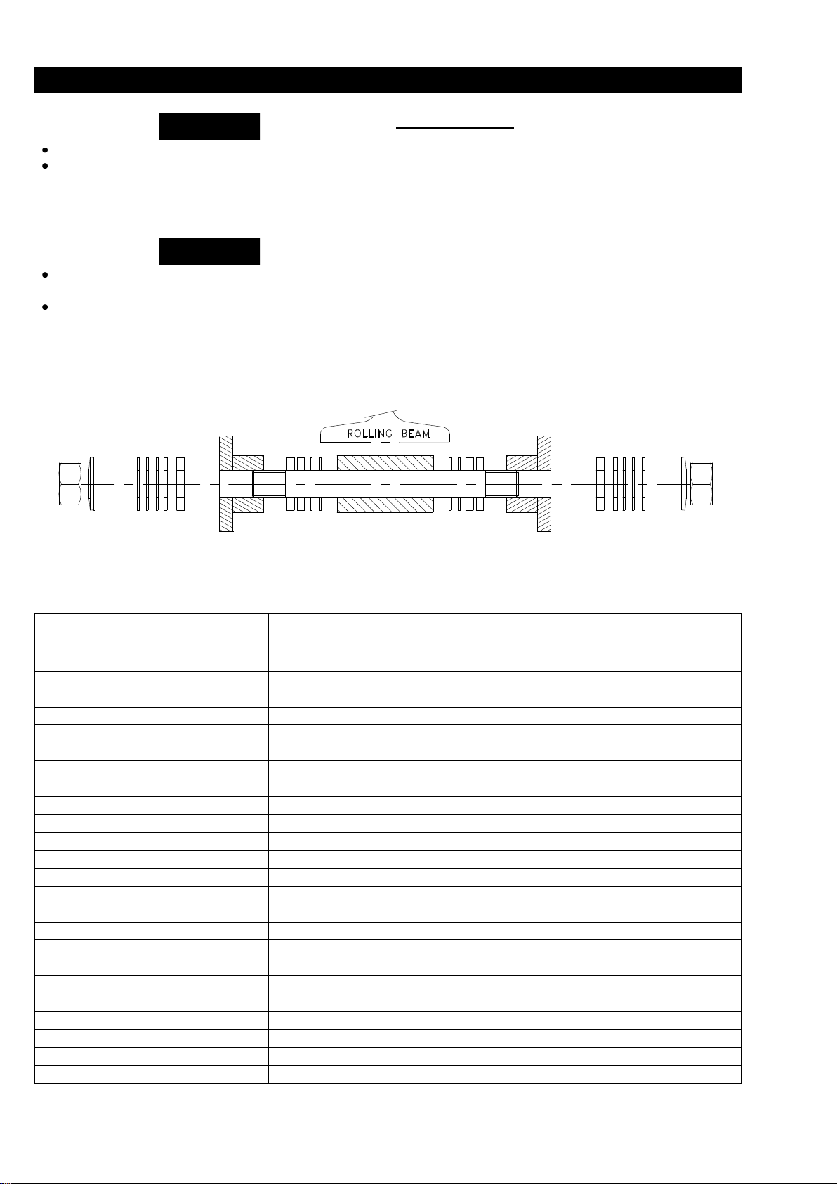
ADJUSTMENT TROLLEY LCA060S TO 250Q « LR »
WARNING
NOTICE
Rolling beam
Additionnal thickness
of distance washer
Thickness of
distance washer
Thickness of
distance washer
to make use adjustment
Additionnal thickness
of distance washer
to make use adjustment
IPN 360-143
35+15+10+6+5+3.5+3.5+3+2.5
0 0 2.5+3+3.5+5+6+10+15+35
IPN 400-155
35+15+10+5+3.5+3.5+3+2.5
6 6 2.5+3+3.5+3.5+5+10+15+35
IPN 450-170
35+15+10+3.5+3.5+3
2.5+5+6
6+5+2.5
3+3.5+3.5+10+15+35
IPN 500-180
35+10+5+3.5+3.5+3+2.5
6+15
15+6
2.5+3+3.5+3.5+5+10+35
IPN 550-200
35+6+5+3.5+3+2.5
3.5+10+15
15+10+3.5
2.5+3+3.5+5+6+35
IPN 600-215
35+3.5+3.5+3+2.5
5+6+10+15
15+10+6+5
2.5+3+3.5+3.5+35
IPE 300-150
35+15+10+6+5+3.5+3+2.5
3.5
3.5
2.5+3+3.5+5+6+10+15+35
IPE 330-160
35+15+10+6+3.5+3+2.5
3.5+5
5+3.5
2.5+3+3.5+6+10+15+35
IPE 360-170
35+15+10+3.5+3.5+3
2.5+5+6
6+5+2.5
3+3.5+3.5+10+15+35
IPE 400-180
35+10+6+5+3.5+3+2.5
3.5+15
15+3.5
2.5+3+3.5+5+6+10+35
IPE 450-190
35+10+6+3.5+3+2.5
3.5+5+15
15+5+3.5
2.5+3+3.5+6+10+35
IPE 500-200
35+6+5+3.5+3+2.5
3.5+10+15
15+10+3.5
2.5+3+3.5+5+6+35
IPE 535-210
35+5+3.5+3.5+3
2.5+6+10+15
15+10+6+2.5
3+3.5+3.5+5+35
IPE 600-220
15+10+6+5+3.5+3+2.5
3.5+35
25+3.5
2.5+3+3.5+5+6+10+15
HE 240
15+6+5+3.5+3+2.5
3.5+10+35
35+10+3.5
2.5+3+3.5+5+6+15
HE 248
15+6+3.5+3.5+3
2.5+5+10+35
35+10+5+2.5
3+3.5+3.5+6+15
HE 260
15+3.5+3.5+3
2.5+5+6+10+35
35+10+6+5+2.5
3+3.5+3.5+15
HE 268
6+5+3.5+3.5+3
2.5+10+15+35
35+15+10+2.5
3+3.5+3.5+5+6
HE 280
6+3.5+3+2.5
3.5+5+10+15+35
35+15+10+5+3.5
2.5+3+3.5+6
HE 288
6+5
2.5+3+3.5+3.5+10+15+35
35+15+10+3.5+3.5+3+2.5
5+6
HE 290
3.5+3.5+3
2.5+5+6+10+15+35
35+15+10+6+5+2.5
3+3.5+3.5
HE 300
5
2.5+3+3.5+3.5+6+10+15+35
35+15+10+6+3.5+3.5+2.5
5
HE 305
2.5
3+3.5+3.5+5+6+10+15+35
35+15+10+6+5+3.5+3.5+3
2.5
HE 310
0
2.5+3+3.5+3.5+5+6+10+15+35
35+15+10+6+5+3.5+3.5+3+2.5
0
Before installing read "SAFETY INFORMATION",
Make sure trolley wheels are compabible with the
beam. Tapered wheels are for use only with "I"
beams (IPN) ; flat tread wheels are for use only with
"H" type beams (IPE).
Trolley wheels ride on the top of the lower flange of
the beam.
During assembly lubricate gears, nuts, capscrews,
and all machined threads with applicable lubricants.
Use of antiseize compound and/or thread lubricant
on capscrew and nut threaded areas prevents
corrosion.
Adjustment Trolley
Refer.Dwg.D5440207
According to travelling beam used
The adjustment is realized with the distance washer :
2.5-3-3,5 - 5 - 6 - 10 - 15 and 35 mm thick
(Rep. 23-26-27-28-35-36-43-52).
1. Stack un the washers as notified on the following
sheet.
2. Position the tightening washers Rep. 31.
3. Tighten the nuts Rep. 51 at 110 mdaN.
Tightening washer Distance Trolley Distance Hoist Distance Trolley flange Distance Tightening washer
+ nut washer flange washer washer washer +nut
Page 9

9
SPECIFICATIONS LC2A015S/030D
Page 10
10
SPECIFICATIONS LCA030S/060D
*
* Not applicable for LCA---2LGU
Page 11
11
SPECIFICATIONS LCA070D
Page 12
12
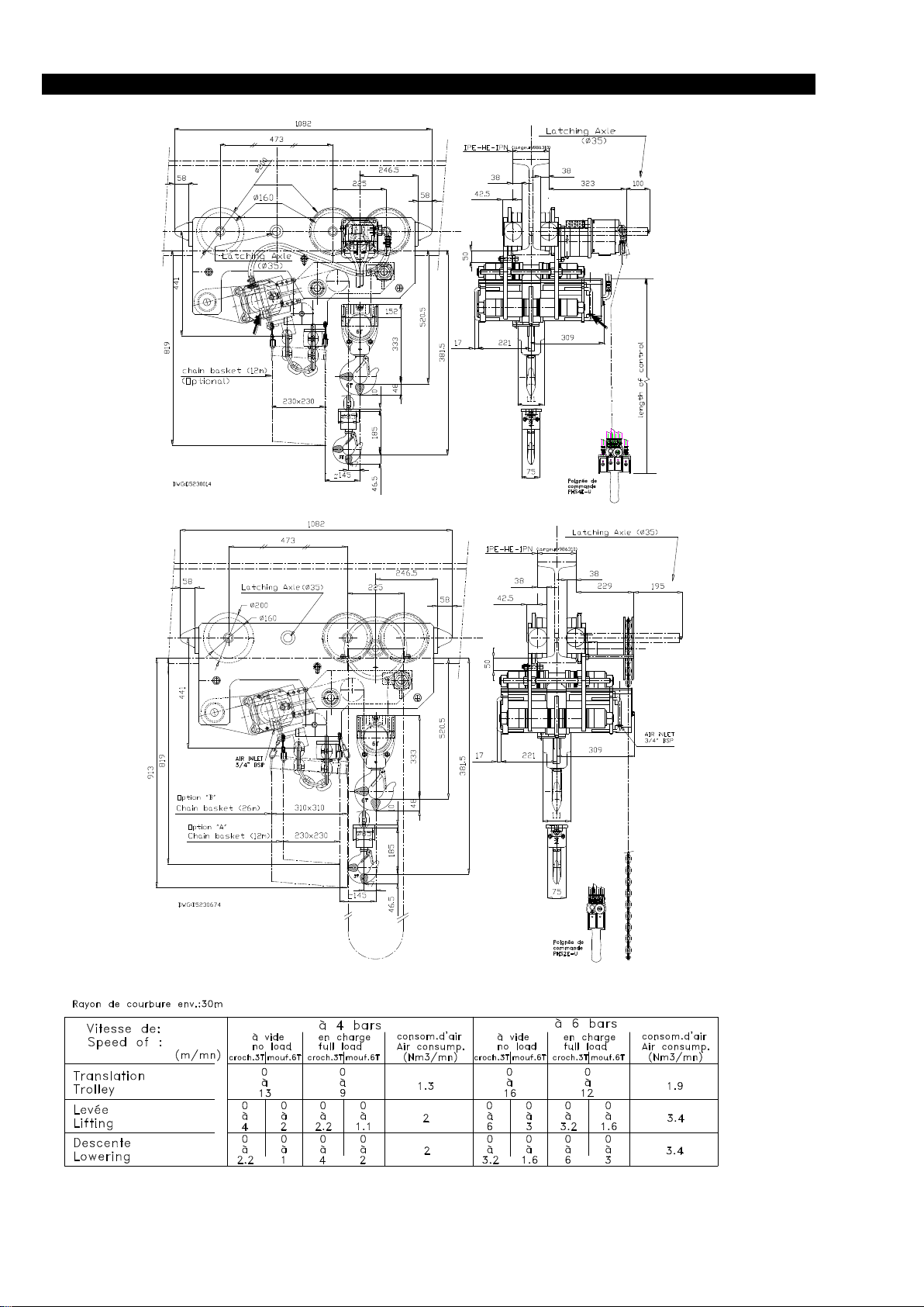
SPECIFICATIONS LCA060S/080D/120D
Page 13
13
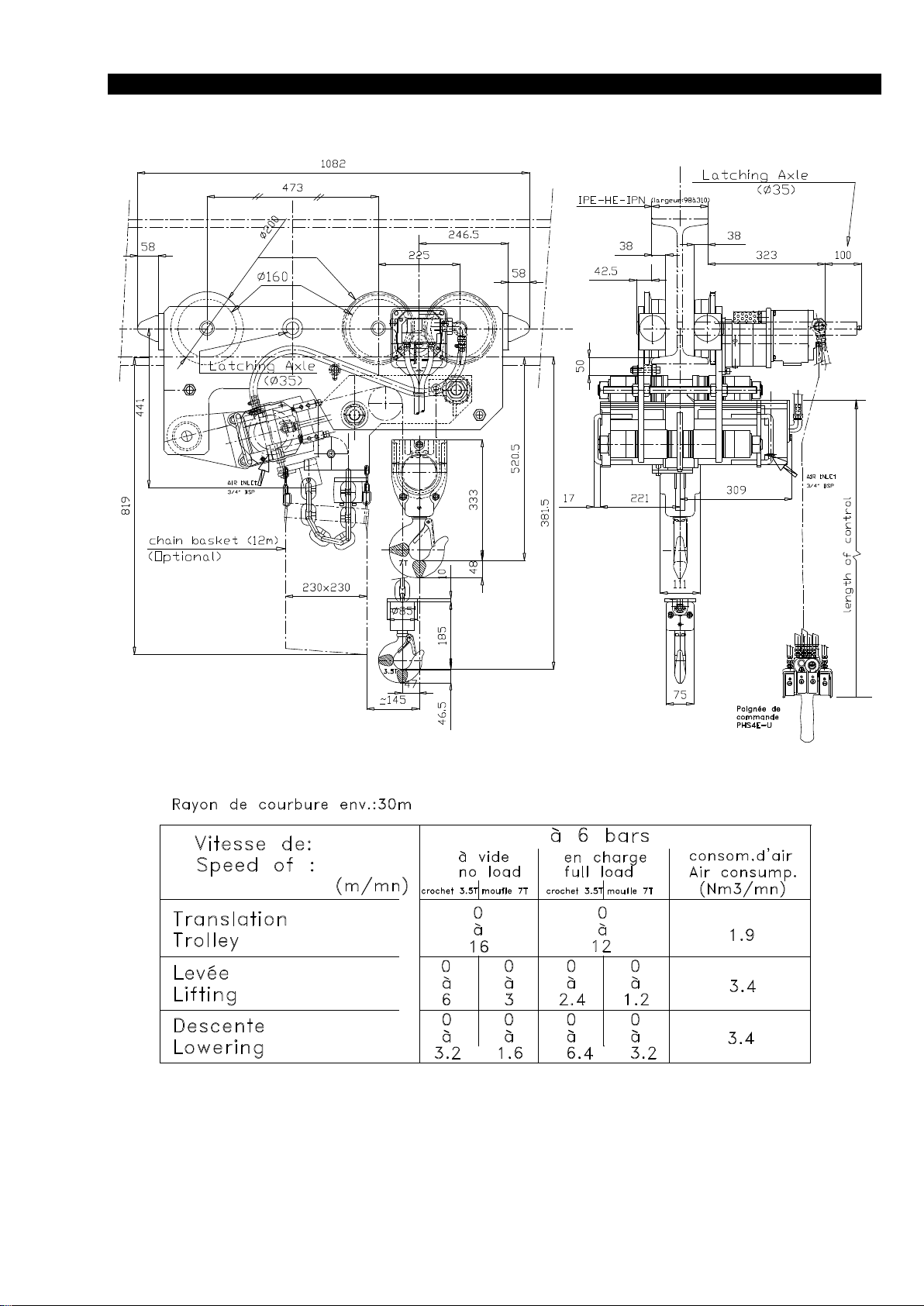
SPECIFICATIONS LCA250Q
Page 14
14
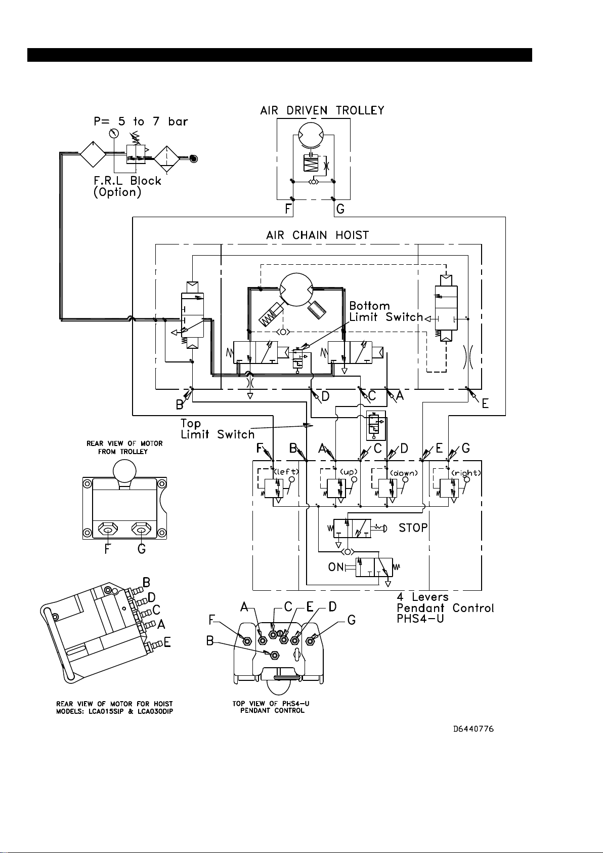
PNEUMATIC SCHEME (LC2A015S/LC2A030D)
Page 15
15
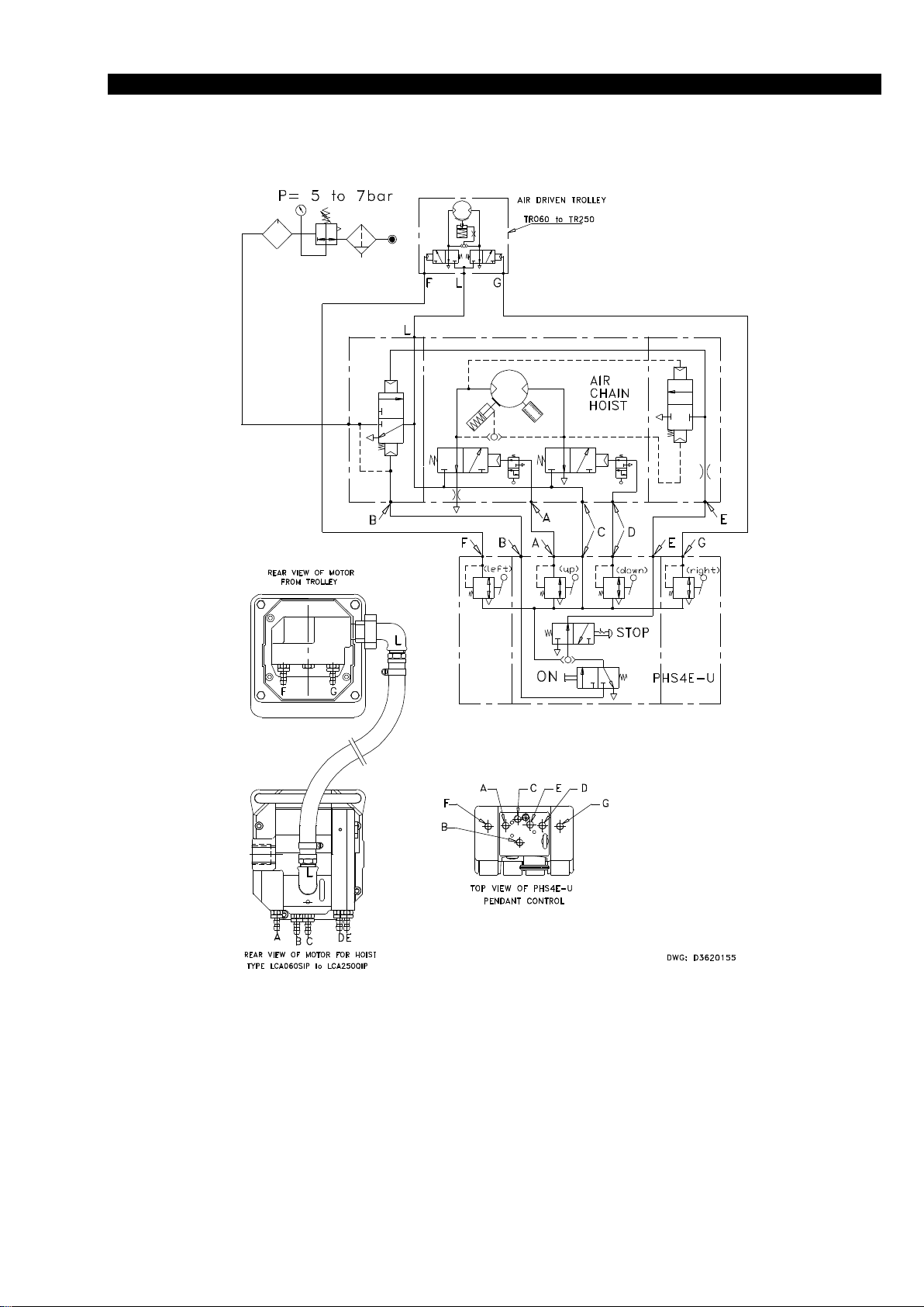
PNEUMATIC SCHEME (LCA030S TO LCA250Q)
Page 16
16
OPERATION
(Dwg.MHP1547)
The four most important aspects of hoist operation are:
1. Follow all safety instructions when operating the hoist.
2. Allow only people trained in safety and operation of
this product to operate the hoist.
3. Subject each hoist to a regular inspection and
maintenance program .
4. Be aware of the hoist capacity and weight of load at all
times.
Operators must be physically competent. Operators must
have no health condition which might affect their ability to
act, and they must have good hearing, vision and depth
perception. The hoist operator must be carefully instructed
in his or her duties and must understand the operation of the
hoist, including a study of the manufacturer's literature. The
operator must thoroughly understand proper methods of
hitching loads and should have a good attitude regarding
safety. It is the operator's responsibility to refuse to operate
the hoist under unsafe conditions.
Initial Operating Checks
Hoists are tested for proper operation prior to leaving the
factory. Before the hoist is placed in service the following
initial operating checks should be performed.
1. After installation of trolley mounted hoists, check to
ensure the hoist is centered below the trolley.
2. Check for air leaks in the supply hose and fittings to
pendant, as well as from pendant to manifold.
3. When first running the hoist or trolley motors, some light
oil should be injected into the inlet connection to allow
good lubrication.
4. When first operating the hoist and trolley it is
recommended that the motors be driven slowly in both
directions for a few minutes.
5. Operate the trolley along the entire length of the beam.
6. Inspect hoist and trolley performance when raising,
moving and lowering test loads. Hoist and trolley must
operate smoothly and at rated specifications prior to
being placed in service.
7. Check that trolley and hook movement is in the same
direction as arrows and pendant control labels.
8. Raise and lower a light load to check operation of the
hoist brake.
9. Check hoist operation by raising and lowering a load
equal to the rated capacity of the hoist a few inches (cm)
off the floor.
10. Check operation of limit devices.
11. Check to see that the hoist is directly over the load. Do
not lift the load at an angle ("side pull" or "yard").
12. Check to see the hoist is securely connected to the
overhead crane, monorail, trolley or supporting
member.
13. Check to see that the load is securely inserted in the
hook, and that the hook latch is engaged.
WARNING
• Allow only personnel trained in safety and operation
of this product to operate hoist and trolley.
• The hoist is not designed and not suitable for lifting,
lowering or moving people. Never lift loads over people.
WARNING
• The hook latch is intended to retain loose slings or
devices under slack conditions. Hook latches are not
intended to be anti-fouling devices, so caution must be
used to prevent the latch from supporting any of the
load.
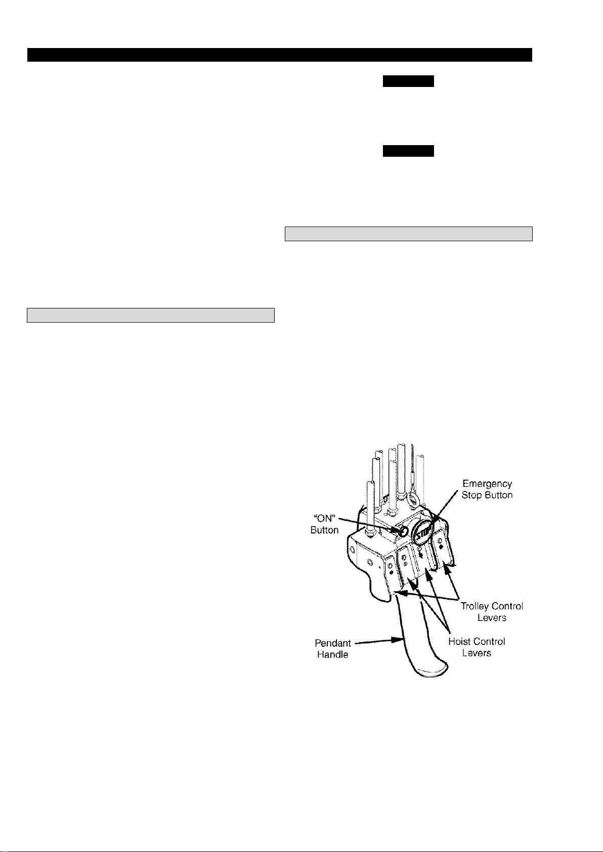
Pendant
The pendant is a remote control that allows the operator to
control the positioning of a load. It will allow the operator
to control hoist movements from a distance, thereby
allowing exact positioning of a hook.. The four lever
pendant controls both hook and trolley positions.
Emergency Stop
The Emergency Stop button, when activated, will
immediately stop all operations of the hoist and trolley.
The Emergency Stop button will remain depressed after
activation.
To reset four lever pendants Emergency Stop button twist
(rotate) Emergency Stop button clockwise until button
releases and spring returns to its original position. Depress
"ON" button.
Page 17

17
INSPECTION
WARNING
• All new, altered or modified equipment should be
inspected and tested by personnel instructed in safety,
operation and maintenance of this equipment to ensure
safe operation at rated specifications before placing
equipment in service.
• Never use a hoist that inspection indicates is damaged.
Frequent and periodic inspections should be performed on
equipment in regular service. Frequent inspections are
visual examinations performed by operators or personnel
trained in safety and operation of this equipment and
include observations made during routine hoist operation.
Periodic inspections are thorough inspections conducted by
personnel trained in the safety, operation and maintenance
of this equipment.
The states inspection intervals depend upon the nature of
the critical components of the equipment and the severity of
usage. The inspection intervals recommended in this
manual are based on intermittent operation of the hoist
eight hours each day, five days per week, in an environment
relatively free of dust, moisture and corrosive fumes. If the
hoist is operated almost continuously or more than the eight
hours each day, more frequent inspections will be required.
Careful inspection on a regular basis will reveal potentially
dangerous conditions while still in the early stages,
allowing corrective action to be taken before the condition
becomes dangerous.
Deficiencies revealed through inspection, or noted during
operation, must be reported to designated personnel
instructed in safety, operation and maintenance of this
equipment. A determination as to whether a condition
constitutes a safety hazard must be made, and the correction
of noted safety hazards accomplished and documented by
written report before placing the equipment in service.
Records and Reports
Inspection records, listing all points requiring periodic
inspection should be maintained for all load bearing
equipment.
Written reports, based on severity of service, should be
made on the condition of critical parts as a method of
documenting periodic inspections. These reports should be
dated, signed by the person who performed the inspection,
and kept on file where they are readily available for review.
Load Chain Reports
Records should be maintained documenting the condition
of load chain removed from service as part of a long-range
load chain inspection program. Accurate records will
establish a relationship between visual observations noted
during frequent inspections and the actual condition of the
load chain as determined by periodic inspection methods.
Frequent Inspection
On hoists in continuous service, frequent inspections should
be made by operators at the beginning of each shift. In
addition, visual inspections should be conducted during
regular service for any damage or evidence of malfunction.
1. OPERATION. Check for visual signs or abnormal noises
(grinding, etc.) which could indicate a potential
problem. Make sure all controls function properly and
return to neutral when released. Check chain feed
through the hoist and bottom block. If chain binds,
jumps, is excessively noisy or "clicks," clean and
lubricate the chain. If the problem persists, replace the
chain. Do not operate the hoist until all problems have
been corrected.
2. UPPER AND LOWER LIMIT DEVICE. Test operation
with no load slowly in both extremes of travel. Upward
travel must stop when the stop buffer on the bottom
block hits hoist limit switch. Downward travel must
stop when the stop buffer attached to the end of the
unloaded load chain decreases and activates the limit
switch.
3. HOOKS. Check for wear or damage, increased throat
width, bent shank or twisting of hook. Replace hooks
which exceed the throat opening discard width or which
exceed a 10° twist. If the hook latch snaps past the tip of
the hook, the hook is sprung and must be replaced.
Check hook support bearings for lubrication or damage.
Ensure that they swivel easily and smoothly.
4. HOOK LATCH. Make sure hook latch is present and
operating. Replace if necessary.
CAUTION
• Do not use hoist if hook latch is missing or damaged.
5. CONTROLS. During operation of the hoist, verify that
response to pendant is quick and smooth. See that the
controls return to neutral when released. If hoist responds
slowly or movement is unsatisfactory, do not operate the
hoist until all problems have been corrected.
6. AIR SYSTEM. Visually inspect all connections, fittings,
hoses and components for indication of air leaks. Repair
any air leaks found. Check and clean the filter.
7. LOAD CHAIN. Examine each of the links for bending,
cracks in weld areas or shoulders, traverse nicks and
gouges, weld splatter, corrosion pits, striation (minute
parallel lines) and chain wear, including bearing surfaces
between chain links. Replace a chain that fails any of the
inspections. Check chain lubrication and lubricate if
necessary. Refer to "Load Chain" in the "LUBRICATION"
section.
NOTICE
• The full extent of load chain wear cannot be
determined by visual inspection. At any indication of
load chain wear, inspect the chain and chain wheel in
accordance with instructions in "Periodic Inspection."
8. LOAD CHAIN REEVING. Ensure welds on standing
links are away from load sheave. Reinstall chain if
necessary. Make sure chain is not capsized, twisted or
kinked.
Page 18

18
LC2A015S / LC2A030D :
Chain size 8x24 G8 (69089432)
Normal Length: 120 mm
Discard Length: 122 mm
LCA030S / LCA060D :
Chain size 13x36 G6 (69087432)
Normal Length: 180 mm
Discard Length: 183 mm
LCA035S / LCA070D :
Chain size 13x36 G8 (69054232)
Normal Length: 180 mm
Discard Length: 183 mm
LCA060S to LCA250Q :
Chain size 16 x 45 G8 (69087532)
Normal Length: 225 mm
Discard Length: 228 mm
Periodic Inspection
frequency of periodic inspection depends on severity of
usage:
NORMAL HEAVY SEVERE
yearly semiannually quarterly
Disassembly may be required for HEAVY or SEVERE
usage. Keep accumulative written records of periodic
inspections to provide a basis for continuing evaluation.
Inspect all the items in "Frequent Inspection." Also inspect
the following:
1. FASTENERS. Check all rivets, split pins, capscrews and
nuts. Replace if missing or tighten if loose.
2. ALL COMPONENTS. Inspect for wear, damage,
distortion, deformations and cleanliness. If external
evidence indicates the need, disassemble. Check gears,
shafts, bearings, sheaves, chain guides, springs and
covers. Replace worn or damaged parts. Clean, lubricate
and reassemble.
3. HOOKS. Inspect hooks carefully for cracks using
magnetic particle or other suitable non-destructive
method. Inspect hook retaining parts. Tighten or repair
if necessary.
4. LOAD CHAIN SPROCKET. Check for damage or
excessivewear. Replace if necessary. Observe the action
of the load chain feeding through the hoist. Do not
operate a hoist unless the load chain feeds through the
hoist and hook block smoothly and without audible
clicking or other evidence of binding or malfunctioning.
5. MOTOR. If performance is poor, disassemble the motor
and check for wear or damage to bearings and shafts.
The parts should be cleaned, lubricated and
reassembled. Replace worn or damaged parts.
6. BRAKE. Raise a load equal to the rated capacity of the
hoist a few inches (cms) off the floor. Verify hoist holds
the load without drift. If drift occurs, disassemble.
Remove the brake discs as described in the
"MAINTENANCE" section. Check and clean the brake
parts each time the hoist is disassembled. Replace the
brake discs if the grooves are no longer visible.
7. SUPPORTING STRUCTURE. Check for distortion,
wear and continued ability to support a load.
8. TROLLEY (if equipped). Check that the trolley wheels
track the beam properly and trolley is correctly adjusted
in accordance with manufacturer's literature. Check that
wheels and beam are not excessively worn and inspect
side plates for spreading due to bending. Do not operate
the hoist until the problem has been determined and
corrected.
9. LABELS AND TAGS. Check for presence and legibility.
Replace if necessary.
10. LOAD CHAIN END ANCHORS. Ensure both ends of
the load chain are securely attached. Secure if loose,
repair if damaged, replace if missing. Check chain
stoppers are correctly installed and functional.
11. LOAD CHAIN. Measure the chain for stretching.
Measure the load chain over the outside of five link
sections all along the the chain, paying particular
attention to the most frequently reeved links. When any
five links in the working length reaches or exceeds the
discard length, replace the entire chain. Always use
genuine Ingersoll-Rand Material Handling replacement
chain. Zinc plated load chain is standard on Liftchain
hoists.
12. CHAIN CONTAINER. Check for damage or excessive
wear and that chain container is securely attached to the
hoist. Secure or replace if necessary.
13 LIMIT SWITCH. Check limit switches function
correctly.
Hoists Not in Regular Use
1. A hoist which has been idle for a period of one month or
more, but less than one year, should be given an
inspection conforming to the requirements of "Frequent
Inspection" prior to being placed in service.
2. A hoist which has been idle for a period of more than one
year should be given an inspection conforming to the
requirements of "Periodic Inspection" prior to being
placed in service.
3. Standby hoists should be inspected at least semiannually
in accordance with the requirements of "Frequent
Inspection." In abnormal operating conditions, hoists
should be inspected at shorter intervals.
Page 19

19
LUBRICATION Frequency by usage level
Component
Severe
Heavy
Normal
Load chain
Daily
Weekly
At usage
Hook
Daily
Weekly
At usage
Gear case
Yearly
Every 3 years
Unnecessary
Model
Gear Casing
(ml)
Motor Casing
(ml)
LC2A015S and
LC2A030D
150
N/A
LCA030S
LCA060D and
LCA070D
400
150
LCA060S
to
LCA250Q
750
150
Ambient Temperature
Recommendes Oil Type
Below (0°C)
ISO VG22 (50W)
(0° to 26°C)
ISO VG 150 (90W)
Above (26°C)
ISO VG 460 (140W)
To ensure continued satisfactory operation of the hoist, all
points requiring lubrication must be serviced with the
correct lubricant at the proper time intervals indicated for
each assembly. Correct lubrication is one of the most
important factors in maintaining efficient operation.
The lubrication intervals recommended in Table 6 are based
on intermittent operation of the hoist eight hours each day,
five days per week. If the hoist is operated almost
continuously, or for more than eight hours each day, or
under severe conditions, more frequent lubrication will be
required.
Table 6
Lubricant types and change intervals are based on operation
in an environment relatively free of dust, moisture and
corrosive fumes. Use only those lubricants recommended.
Other lubricants may affect performance of the hoist.
Approval for the use of other lubricants must be obtained
from your Ingersoll-Rand Technical Support Department
or distributor. Failure to observe this precaution may result
in damage to the hoist and/or its associated components.
Whenever a hoist is disassembled for overhaul or
replacement of parts, lubricate as follows:
Brake and Gear Assemblies
The gear and brake assemblies share a common oil bath. On
larger capacity hoists, the output shaft from the motor is
offset and utilizes a pinion gear to drive the sun gear. These
gears operate in the motor casing oil bath.
LCA030S and Larger Hoists Oil Fill Level Positions
Fill to the level of the plug on the side of the motor
housing and on the gear end in the center of the brake
end cover.
Replace the oil in the brake and gear housing in accordance
with Table 6 recommendations. Refer to Table 8 for
recommended oil type. If hoist use is at normal frequency,
the oil in the reduction housing is suitable for one year's
operation without changing.
However, when hoist use is at greater frequency, or under
severe conditions, the oil may need to be changed more
often. To ensure correct performance, highest efficiency
and long life, it is essential that the lubricating oil be
maintained at the correct level. The recommended grade of
LUBRICATION
oil must be used at all times since the use of unsuitable oil
may result in excessive temperature rise, loss of efficiency
and possible damage to the gears.
Liftchain hoists are shipped from the factory with oil in the
brake and reduction gear assembly.
Table 8
Hook Assemblies
Hoist top and bottom hooks are supported by thrust
bearings. These bearings must be packed with Ingersoll-
Rand No. 68 Grease or a standard No. 2 multi-purpose
grease at regular intervals. Neglect of proper lubrication can
lead to bearing failure.
1. Lubricate the hook and latch pivot points. Hook and latch
should swivel/pivot freely.
2. Use Ingersoll-Rand LUBRI-LINK-GREEN ® or ISO
VG 220 (50W) lubricant.
3. Lubricate hook bearings by applying several shots of
grease from a grease gun to the grease fittings provided
on the hook blocks.
Air Line Lubricator
If an air line lubricator is used, it should be replenished
daily with ISO VG 100 (30W) lubricant (minimum
viscosity 135 Cst at 104° F (40° C)).
Trolley
Grease the wheel bearings and wheel drive gear with
Ingersoll-Rand No. 68 Grease or a standard No. 2 multipurpose grease periodically. Refer to the manufacturer's
literature for additional lubrication information.
Load Chain
WARNING
• Failure to maintain a clean and well-lubricated load
chain will result in rapid load chain wear that can lead
to chain failure which can cause severe injury, death or
substantial property damage.
1. Lubricate each link of the load chain weekly. Apply new
lubricant over existing layer.
2. In severe applications or corrosive environments,
lubricate more frequently than normal.
3. Lubricate hook and hook latch pivot points with same
lubricant used on the load chain.
4. If required, clean chain with acid free solvent to remove
rust or abrasive dust buildup and lubricate the chain.
5. Use Ingersoll-Rand LUBRI-LINK-GREEN ® or ISO
VG 220 (50W) oil.
Page 20

20
MAINTENANCE
WARNING
INTERVAL
MAINTENANCE CHECK
Start of each shift
Make a thorough visual inspection of the
hoist for damage. Do not operate the hoist if
damage is found.
Operate in both directions. Hoist must
operate smoothly without sticking, binding
or abnormal noises.
Check the operation of the brake.
Quarterly
Remove, clean or replace muffler in top of
gear housing.
Yearly
Inspect the hoist gearing, shafts and bearings
for damage or wear. Repair or replace as
necessary.
Check all of the supporting members,
including the trolley if used. Repair or
replace as required.
NOTICE
A
A
14,5 mini
7,5 mini
• Never perform maintenance on the hoist while it is
supporting a load.
• Before performing maintenance, tag controls:
DANGER - DO NOT OPERATE EQUIPMENT BEING REPAIRED.
• Only allow personnel trained in operation and service of this
hoist to perform maintenance.
• After performing any maintenance on the hoist dynamically
test the hoist to 100% of its rated capacity, in accordance with
ASME B30.16 standards, before returning hoist to service.
Testing to more than 100% of rated capacity is required to set
overload device and may be required to comply with
standards and regulations set forth in areas outside the USA.
• Shut off air system and depressurize air lines before
performing any maintenance.
Proper use, inspections and maintenance increase the life and
usefulness of your Ingersoll-Rand equipment. During assembly,
lubricate gears, bearings and shafts with applicable lubricants.
Use of a thread locking compound and/or thread lubricant on
capscrew and nut threaded areas helps prevent corrosion of
components.
Maintenance Intervals
The Maintenance Interval Chart below is based on intermittent
operation of equipment for eight hours each day, five days per
week. If the equipment is in operation for more than eight hours a
day or is operated in severe applications or environments, more
frequent maintenance should be performed.
LC2A015S and LC2A030D Hoists
(D6440775)
LCA030S TO LCA250Q Hoists
Adjustments
No brake adjustment is required.
Annual Maintenance is limited to:
1. A general cleaning.
2. The friction discs have a 0.2 mm (0.079 in.) deep groove on
each side. Replace the friction discs if the grooves are no longer
visible. Refer to Dwg. D6440775 or D4120242.
3. Measure total brake and steel plate stack up. Check that
measurement is not less than minimum shown.
Brake
(Dwg. D4120242)
Overload Device
1. Connect the hoist to the air supply.
2. Release the locknut and turn the adjustment screw in order to
increase or decrease the SWL (increase the SWL by
tightening the adjustment screw). The adjustment must be
made for an overload of 20% maximum of the SWL.
3. Tighten the locknut securing the adjustment screw.
4. Check hoist operation at rated load. If necessary repeat the
adjustment.
OTICE
• Do not change factory settings unless hoist is tested and
recertified at an authorized repair facility.
(Dwg. D4120413)
Page 21

21
Disassembly
WARNING
• Disconnect the air supply hose before performing any
maintenance or repairs on this hoist.
General Instructions
All maintenance work done on the Liftchain hoist should be
performed on a bench in a clean dust free work area. In
the process of disassembling the hoist, observe the
following:
1. Never disassemble the hoist any further than is necessary
to accomplish the needed repair. A good part can be
damaged during the course of disassembly.
2. Never use excessive force when removing parts. Tapping
gently around the perimeter of a cover or housing with a
soft hammer, for example, is sufficient to break the seal.
3. Do not heat a part with a flame to free it for removal,
unless the part being heated is already worn or damaged
beyond repair and no additional damage will occur to
other parts. In general, the hoist is designed to permit
easy disassembly and assembly. The use of heat or
excessive force should not be required.
4. Keep the work area clean to prevent dirt and other
foreign matter from getting into bearings and other
moving parts. 5. All seals and 'O' rings should be
discarded once they have been removed. New seals and
'O' rings should be used when assembling the hoist.
6. When grasping a part in a vise, always use leather- or
copper-covered vise jaws to protect the surface of the
part and help prevent distortion. This is particularly true
of threaded members, machined surfaces and housings.
7. Do not remove any part which is press fit in or on a
subassembly unless the removal of the part is necessary
for repairs or replacement.
8. To avoid damaging bearings during hoist assembly or
disassembly always tap or press on the bearing inner
race for shaft fit bearings or the outer race for bore fit
bearings.
9. For assembly work above body height, suitable working
platforms or ladders should be made available.
10. Do not attempt to wash sealed bearings.
If hoists are to be completely disassembled it is
recommended that the motor assembly and brake/gear
housing assembly be removed as complete assemblies from
the chain guide housing. This can be accomplished by
removing the capscrews, nuts and washers that clamp the
housings together. Carefully separate assemblies and clean
mating surfaces. Assemblies are Loctited together.
The muffler is located in the top of the gear housing. To
clean muffler remove retainer ring in gear housing and with
the aid of small pick remove the first muffler plate. Remove
'O' ring, second muffler plate and last 'O' ring.
Load Chain Replacement
WARNING
• NEVER splice a load chain except when installing a
new load chain by the following method. Always discard
the link used to connect the old chain with the new.
Excessive chain wear cannot be detected by casual
observation. The chain is case hardened and once the case
hardening is worn through, wear will progress rapidly and
the strength of the chain will be considerably reduced.
Further, the chain will no longer fit the chain sprocket
properly, greatly increasing the chance of malfunction and
chain breakage.
One chain sprocket will outlast several chains if the chain is
replaced as recommended. The use of a worn chain will
cause the chain sprocket to wear rapidly.
If the chain is visibly damaged, examine the chain sprocket
and chain guide. Install a new chain sprocket if the old one
is visibly worn. Install a new guide if the old one is broken
or distorted.
NOTICE
• For ease of installation, do not remove the old chain
from the hoist. Use the old chain to feed the new chain
through the hoist.
1. The hoist must be hung and connected to the air supply.
Reduce air pressure to 60 psi (4 bar).
2. Remove chain bucket, if used.
3. Remove free end of chain from hoist body, if attached.
Remove chain buffer and limit stop.
4. Remove the load hook.
5. Run hoist slowly in the lifting direction until the chain
free end is approximately 2 ft (60 cm) from the hoist.
6. Using an abrasive wheel, cut a section from the last link.
Use a 'C' link which is the same size as the chain.
CAUTION
• Do not distort the link in any manner. It must be able
to pass over the pocket and idler wheels without
binding.
7. Connect the new chain to the old chain by hooking the
end of the new chain onto the 'C' link. Make certain the
welds and links on the new chain match the positioning
of the welds and links on the chain being replaced.
CAUTION
• Ensure that chain does NOT become twisted during
reeving. All chain welds must align while chain is
hanging free.
8. Slowly run the hoist in the raise direction, running off the
old chain and reeving the new chain over the chain
wheel.
The first link of new chain over the chain wheel must
be a standing link.
9. Reinstall the load hook, chain buffer and limit stop
WARNING
• A twisted chain can jam as it passes over the pocket
wheel, possibly resulting in damage to the hoist or even
breaking the chain and causing injury.
Page 22

22
General Trolley Disassembly
NOTICE
• Prior to disassembly note the installation of the adjusting
spacers Install adjusting spacers during
assembly, in the same configuration recorded during
disassembly to ensure beam flange width and hoist position
are retained.
• Prior to disassembly of trolley, first remove trolley motor,
bottom hook ass‟y, load chain and then remove hoist.
For remove the hoist refer to LIFTCHAIN AIR HOIST
Manual ref :SAM0208
Remove the trolley from the beam by removing end stop and after
adequately supporting trolley, run trolley off the beam.
CAUTION
• Support trolley adequately as it comes off beam to prevent
injury and/or damage to equipment. If that is not possible,
loosen or remove only one side plate. Refer to “Side Plate
Disassembly”.
General Disassembly Hoist (LC2A015S/LC2A030D)
Dwg..D6440774
1. Remove the chain and the bottom hook.
2. Remove the chain basket
3. Disconnect all hoses
- Trolley Disassembly
1. Remove one nut (66) from outside of side plate.
No required for LCA015S and LCA030D
2. Remove nuts (28) and, washers (30) from same side
plate. Separate side plate until it is free of beam.
Remove trolley to a clean dust free work area for repair.
1. Remove the other outside nut (66).
2. Remove all nuts (28) and washers (30).
3. Separate the side plate from tie rods (29).
- Plain & Geared Wheel Disassembly
LCA015S/LCA030D
1. Remove retainer ring (49) and pull wheel (50) off of axle
2. Remove retainer ring (47) and pull bearing(s) (48) out of wheel.
a-Large wheel :
1. Remove retainer ring (33) and pull wheel (51) off of axle.
2. Remove retainer ring (31) and pull bearing(s) (32) out of
wheel.
b-Small wheel :
- Return Sprocket Wheel Disassembly
1. Remove nut (20) and pull axle (21) from sprocket wheel
support.
2. Separate sprocket wheel assy from support.
3. Remove Bushing (22) and discard.
- 1.5 and 3 ton Motor Unit Disassembly
1. Disconnect air hoses from power unit.
2. Remove capscrews (18) and lockwashers (19).
3. Remove power unit assembly from trolley side plate.
1.5 and 3 ton Motor Disassembly
Refer to Dwg. D5240240
1. Remove capscrews (220) and lockwashers (221).
2. Remove plate (222). Remove key (218) from spindle shaft
(217).
3. Remove gears (226, 227, 229), washers (223) and thrust race
(228) from motor housing (254).
Spindle assembly (215 through 219) should not be removed from
plate (222) unless repair is required.
4. To remove spindle assembly from plate:
a. Remove retainer ring (219).
b. Tap end of spindle shaft (217) to remove from plate
(222).
5. To remove motor assembly (items 239 through 251):
a. Remove capscrews (238) from brake cone (237).
b. Grasping pinion shaft (231) pull assembly free of motor
housing (254).
6. To disassemble motor assembly (items 239 through 251):
a. Remove nut (230) and separate components (231
through 251).
General Disassembly Hoist (LCA030S to LCA250Q)
Dwg..D5240459 / D5440207 / D5960678
1. Remove the chain and the bottom hook.
2. Remove the chain basket
3. Disconnect all hoses
- Trolley Disassembly
1. Remove the screw (41) and extract the motoreducer.
2. Remove the hoist to the support (54).
3. Remove the nut (58) (1 external side of the flange)
4. Remove the nut (51) (3 external side of the flange) and
the external spacers.
5. Remove the sub assembly trolley flange (12) and the
internal spacers
6. Remove the return sprocket wheel support (11)
7. Remove the support (54) and the spacer ring (29).
8. Remove another motorised trolley flange unit (13).
- Plain & Geared Wheel Disassembly
LCA030S/LCA060D/LCA070D
1. Remove the external retainer ring(3) and extract the
rollers wheel (9)
2. ). Remove the internal retainer ring(63) and extract the
ball bearing (33)
Plain & Geared Wheel Disassembly
LCA060S to LCA250Q
1. Remove the nut (50) and extract the roller axle (25).
2. Remove the distance ring (32) and the "O" ring (60).
3. Remove the retainer ring(65) and extract the rollers
bearings (33).
- Return Sprocket Wheel Disassembly
1. Remove the nut (50) and extract the axle (15).
2. Remove the distance ring (17) and extract the return
wheel (14).
3. Remove the rollers bearings (34) and the distance ring
(18).
4. Remove the nut (49) and extract the screw (44).
5. Remove the roller (22).
Page 23

23
Refer to same disassembly instructions in the Maintenance
Manual SAM0208
Accessing the Brake
2HP & 4 HP with Emergency Stop and Overload
Refer to same disassembly instructions in the Maintenance
Manual SAM0208
Reduction Housing
Refer to same disassembly instructions in the Maintenance
Manual SAM0208
Chain guide Housing
Refer to same disassembly instructions in the Maintenance
Manual SAM0208
Clear Inspection & repair
Cleaning
Use the following procedures to clean, inspect and repair
the components of the hoist.
CAUTION
• Bushings that rotate in the frame or are loose or worn
must be replaced. Failure to observe this precaution will
result in additional component damage.
Clean all hoist component parts in solvent (except for the
friction discs). The use of a stiff bristle brush will facilitate
the removal of accumulated dirt and sediments on the gears
and frames. If bushings have been removed, it maybe
necessary to carefully scrape old Loctite ® from the
bushing bores. Dry each part using low pressure, filtered
compressed air.
Inspection
All disassembled parts should be inspected to determine
their fitness for continued use. Pay particular attention to
the following:
1. Inspect all gears for worn, cracked or broken teeth.
2. Inspect all bushings for wear, scoring or galling.
3. Inspect shafts for ridges caused by wear. If ridges caused
by wear are apparent on shafts, replace the shaft.
4. Inspect all threaded items and replace those having
damaged threads.
5. Measure the thickness of the friction disc. Replace the
friction discs if the grooves are no longer visible.
Repair
Actual repairs are limited to the removal of small burrs and
other minor surface imperfections from gears and shafts.
Use a fine stone or emery cloth for this work.
1. Worn or damaged parts must be replaced. Refer to the
applicable Parts Listing for specific replacement parts
information.
2. Inspect all remaining parts for evidence of damage.
Replace or repair any part which is in questionable
condition. The cost of the part is often minor in
comparison with the cost of redoing the job.
3. Smooth out all nicks, burrs or galled spots on shafts,
bores, pins or bushings.
4. Examine all gear teeth carefully and remove nicks or
burrs.
5. Polish the edges of all shaft shoulders to remove small
nicks which may have been caused during handling.
6. Remove all nicks and burrs caused by lockwashers.
Assembly
Brake
Refer to same Assembly instructions in the Maintenance
Manual SAM0208
2HP & 4 HP with Emergency Stop and Overload
Refer to same Assembly instructions in the Maintenance
Manual SAM0208
Reduction Housing
Refer to same Assembly instructions in the Maintenance
Manual SAM0208
Page 24

24
LC2A015S/030DIP3LVU… HOIST ASSEMBLY DRAWING
1
2
3
4
5
6-8
7
9-10
11
12
13
14
15
16
17
18-19
23
24
25-26
27
28
29
30
31
32
33
40
45
46
47
48
49
50
51
21
41
42
26
44
34
35
36
37
38
(Dwg.D6440774#A)
See manual : MHD56297 and respect
the order of assembly below
(D6440776)
43-10
53
52
54
55
22
20
56
57
8
58
Page 25

25
LC2A015S/030DIP3LVU… HOIST ASSEMBLY PARTS LIST
ITEM
DESCRIPTION
QTY
PART NO.
NO.
OF PART
TOTAL.
STANDARD
OPTION „R‟
1
Motor 1 96090229
2
Hoist assembly
1
Refer MHD56297
3
Hoist support 1 96440391
4
Fitting 4 61660732
5
Hose
M
68062032
6
Nut
4
43003511
7
Bumper 4 69805541
8
Lockwasher 5 45201008
9
Screw 2 41326306
10
Lockwasher 4 45201005
11
Air control valve
1
68552732
12
Limit swicth protector
1
95960030
13
Pusher 1 95960031
14
Spring plate 1 95240144
15
Load chain M 69089432
16
Side plate 1 9440384
17
Side plate (motor)
1
96440385
18
Screw 4 41325006
19
Lockwasher 4 45201008
20
Ring
2
95240254
21
Sprocket axle 1 96450025
22
Needle Bearing 2 56462813
23
Sprocket support
1
95248126
24
Sprocket wheel 2 95248139
25
Tie rod 1 95240193
26
Nut
5
43006911
27
Plain wheel
2
95247066
95247072
28
Nut
6
43006711
29
Tie rod 3 95240148
30
Washer
170
45000130
31
Retainer ring 4 47703062
32
Bearing 4 50150006
33
Retainer ring 4 47700030
34
Screw 1 41329606
35
Bearing 1 50150001
36
Distance bearing
1
95230138
37
Washer 1 45001112
38
Locknut 4 43706311
40
Chain container support
4
96440390
41
Screw 1 41326506
42
Washer 1 45001110
43
Screw 2 41322106
44
Lockwasher 1 45201010
45
Trust bearing 2 57319832
46
Pin
1
46501420
47
Retainer ring 2 47703047
Page 26

26
LC2A015S/030DIP3LVU… HOIST ASSEMBLY PARTS LIST
ITEM
DESCRIPTION
TOTAL
PART NO.
NO.
OF PART
QTY.
STANDARD
OPTION „R‟
48
Bearing 2 50150004
49
Retainer ring 2 47700020
50
Plain wheel
2
95700001
96090180
51
Geared wheel
2
95247065
95247071
52
Double fall bottom hook assembly (3 Tons)
1
74240111
74240113
53
Single fall bottom hook assembly (1.5 Ton)
1
74240110
74240112
54
Connector 1 95230151
55
Stop
1
95240255
56
Screw 1 41333206
57
Nut
1
43706511
58
O Ring 2 58215829
Recommended Spare
Page 27

27
AIR CHAIN HOIST ASSEMBLY DRAWING LCA030S / LCA060D / LCA070D
Page 28

28
AIR CHAIN HOIST ASSEMBLY DRAWING LCA030S / LCA060D / LCA070D
Page 29

29
AIR CHAIN HOIST ASSEMBLY PARTS LIST LCA030S / LCA060D./.LCA070D
ITEM
NO.
DESIGNATION
PIECE
DESCRIPTION
OF PART
TOTAL
QTY
PART NO
STANDARD
OPTION ‘R ‘
1
Moto-réducteur frein
Air Moto-rducer with brake
1
3546-0001
2
Pignon 12 dents
2 theeth pinion
1
9523-0010
3
Circlips E35
Retainer Ring 6 4770-0035
4
Roulement à billes
Roller bearing 1 5015-0001
5
Lame ressort
Spring plate 1 9523-0058
6
Bague entretoise
Distance washer
1
9523-0138
7
Ecrou frein
Locknut 2 4370-6311
8
Vis CHc
Screw 1 4132-9606
9
Galet avec couronne dentée
Roller with teeth ring-gear
2
9523-7011
9523-7040
10
Galet lisse
Roller 4 9523-7012
9523-7041
11
Support noix de renvoi
Return sprocket wheel support
1
9523-8096
12
Flasque chariot
trolley flange 1 9523-8148
13
Flasque chariot
Trolley flange 1 9523-8147
14
Noix de renvoi
Return sprocket wheel
1
9523-8055
9523-8114
15
Axe de noix de renvoi
Return sprocket wheel axle
1
9523-7056
16
Tirant
Tie axle 3 9523-7098
17
bague
Ring 1 9523-0060
18
Rondelle entretoise
Distance washer
1
9523-0062
19
Support fin de course
Limit switch support
2
9523-0063
20
Plat de fixation supérieur
Upper flat steel bar
2
9523-0064
21
Plat de fixation intérieur
Internal flat steel bar
2
9523-0065
22
Galet
Roller 1 9523-0069
23
Cale ep:15
Adjusting wedge
6
9523-0105
24
Tige fileté
Screw rod 2 9523-0097
25
Axe de verrouillage du chariot
Latching axle of trolley
1
9523-0110
26
Cale ep:2,5
Adjusting wedge
12
9523-0100
27
Cale ep:3,5
Adjusting wedge
6
9523-0102
28
Cale ep:5
Adjusting wedge
6
9523-0104
29
Bague entretoise
Distance Ring 1 9523-0150
30
Plat
Flat
1
9523-0086
31
Rondelle ressort
Spring washer 6 9523-0115
32
Butée progressive
Progressive stop
4
6988-6832
33
Roulement à billes
Roller bearing
12
5017-0007
34
Roulement à rouleaux
Roller bearing 2 5190-0004
35
Cale ep:3
Adjusting wedge
12
9523-0101
36
Cale ep:4
Adjusting wedge
6
9523-0103
37
Joint
Joint 2 5834-4020
38
Vis H M12
Screw 2 4102-0001
39
Vis CHC M8
Screw 4 4132-1806
40
Vis CHC M8
Screw 8 4132-4906
41
Vis CHC M10
Screw 3 4132-3506
42
Vis CHC M5
Screw 2 4132-6306
43
Cale ep:25
Adjusting wedge
6
9523-0106
44
Vis CHC M14
Screw 1 4130-8606
45
Rondelle M12
Washer 2 4500-1112
46
Vis CHC M14
Screw 1 4132-9106
47
Manchon M.M 1/8‟‟
Nipple 2 6138-5232
48
Ecrou Hu M12
Nut
4
4300-3611
49
Ecrou Frein M14
Locknut 1 75589M
50
Ecrou Hu M20
Nut
9
4300-7311
51
Ecrou Hu M30
Nut
6
4300-6711
Page 30

30
AIR CHAIN HOIST ASSEMBLY PARTS LIST LCA030S / LCA060D / LCA070D
ITEM
NO.
DESIGNATION
PIECE
DESCRIPTION
OF PART
TOTAL
QTY
PART NO
STANDARD
OPTION ‘R ‘
52
Cale ep:42,5
Adjusting wedge
6
9523-0107
53
Ecrou Hm M12
Nut
3
4320-2212
54
Support palan
Support 1 9523-0149
55
Rondelle plate M6 U
Washer 2 4500-1106
56
Rondelle frein W5
Split washer 6 4520-1005
57
Rondelle frein W6
Split washer 2 4520-1006
58
Ecrou frein M8
Locknut 1 75582M
59
Rondelle frein W10
Split washer 3 4520-1010
60
Rondelle frein W12
Split washer 4 4520-1012
61
Rondelle frein W14
Split washer 1 4520-1014
62
Circlips E25
Retainer Ring 1 4770-0025
63
Circlips I72
Retainer Ring 6 4770-3072
64
Rondelle en croix
Crosswise washer
1
9412-0118
70
Support de chaine
Chain support 1 9412-0198
71
Tube lg:0,5mx4
Hose
2m
6806-2032
72
Rondelle en croix
Crosswise washer
1
9523-0067
73
Raccord 1/8 ‟‟
Fitting adapter 2 9523-0151
74
Manchon amortisseur
Sleeve 1 9523-0066
75
Protecteur de fin de course
Limit switch protector
2
9596-0030
76
Poussoir
Pusher 2 9596-0031
77
Distributeur 3/2 cde directe
Control valve with dirct control
2
6855-2732
78
Vis Chc M8
Screw
1
70926M
79
Vis Chc M6
Screw 2 4132-2506
80
About annelé
Fitting 2 6162-9732
81
Raccord instantanné
Fitting 8 6166-0732
82
Vis CHC M5
Screw 4 4132-2106
83
Vis CHC M6
Screw 2 4132-2606
84
Vis M12
Screw 1 4132-5206
89
Chaine (mètre de levée:3T/6T)
Chain (meter of lift:3T/6T)
69087432
100
Crochet 3T
3T Hook
3412-0144
3412-0146
Moufle 6T
6T Bottom Block
3412-0145
3412-0147
101
Palan LCA030S/060D…
Hoist LCA030S/060D…
Refer to SAM0208
ITEM
NO.
DESIGNATION
PIECE
DESCRIPTION
OF PART
TOTAL
QTY
PART NO
STANDARD
OPTION ‘R ‘
9
Galet avec couronne dentée
Roller with teeth ring-gear
2
9523-7040
-
10
Galet lisse
Roller 4 9523-7041
-
14
Noix de renvoi
Return sprocket wheel
1
9523-0194
15
Axe de noix de renvoi
Return sprocket wheel axle
1
9523-0196
17
bague
Ring
1
9523-0195
34
Roulement à rouleaux
Roller bearing 2 5194-0004
54
Support palan
Support 1 9523-0197
89
Chaine (mètre de levée:7T)
Chain (meter of lift:7T)
6905-4232
100
Moufle 7T
7T Bottom Block
3412-0576
-
Pièces de rechange recommandées
/Recommended Spare
SPECIFIC PIECES FOR LCA070D
Page 31

31
AIR CHAIN HOIST ASSEMBLY DRAWING LCA060S / LCA80D / LCA120D
Page 32

32
AIR CHAIN HOIST ASSEMBLY DRAWING LCA060S / LCA80D / LCA120D
Page 33

33
AIR CHAIN HOIST ASSEMBLY PARTS LIST LCA060S / LCA80D / LCA120D
ITEM
NO.
DESIGNATION
PIECE
DESCRIPTION
OF PART
TOTAL
QTY
PART NO
STANDARD
OPTION ‘R ‘
1
Moto-réducteur frein
Air Moto-rducer with brake
1
7546-0001
2
Pignon 12 dents
2 theeth pinion 1 9523-0010
3
Vis Chc M8x10
Screw 1 4132-5606
4
Roulement à billes
Roller bearing 1 5015-0001
5
Lame ressort
Spring plate 1 9523-0058
6
Bague entretoise
Distance washer
1
9523-0138
7
Rondelle Z24
Flat Washer 1 4500-1424
8
Rondelle LL8
Flat Washer 1 4570-1008
9
Galet dentée(IPE)
Geared Wheel (Flat beam IPE)
2
9544-7006
9544-7070
Galet dentée(IPN)
Geared Wheel (Flat beam IPN)
2
9544-7008
9544-7017
10
Galet lisse (IPE)
Plain Wheel (Flat beam IPE)
4
9544-4007
9544-7069
Galet lisse (IPN)
Plain Wheel (Flat beam IPN)
9544-7007
9544-7018
11
Support noix de renvoi
Return sprocket wheel support
1
9544-8133
12
Flasque chariot
Trolley flange 1 9544-8141
13
Flasque chariot coté MRF
Trolley flange (geared)
1
9544-8140
14
Noix de renvoi
Return sprocket wheel
1
9544-8024
95448118
15
Axe de noix de renvoi
Return sprocket wheel axle
1
9544-7025
16
Tirant
Screw Rod 3 9544-7124
17
Bague Epaulée
Distance Ring 1 9544-0027
18
Bague entretoise
Distance Ring 1 9544-0028
19
Support fin de course
Limit switch support
2
9544-0029
20
Plat de fixation supérieur
Upper flat steel bar
2
9544-0030
21
Plat de fixation inférieur
Internal flat steel bar
2
9544-0031
22
Galet
Roller 1 9544-0032
23
Cale ep:15
Spacer (15mm) 6 9544-0131
24
Tige fileté
Screw Rod 2 9544-0123
25
Axe de galet
Roller axle 6 9523-7017
26
Cale ep:2,5
Spacer (2.5mm)
6
9544-0125
27
Cale ep:3,5
Spacer (3.5mm)
12
9544-0127
28
Cale ep:5
Spacer (5mm) 6 9544-0128
29
Bague entretoise
Spacer Ring 1 9544-0143
30
Plat
Flat
1
9544-0041
31
Rondelle ressort
Spring washer 6 9544-0119
32
Bague entretoise
Distance ring 6 9544-0004
33
Roulement à rouleaux NJ207
Roller bearing
12
5120-0007
34
Roulement à rouleaux SL18 2206
Roller bearing 2 5190-0206
35
Cale ep:3
Spacer (3mm) 6 9544-0126
36
Cale ep:6
Spacer (6mm) 6 9544-0129
37
Joint NILOS
Joint
2
5833-4006
38
Vis HM 16x45
Screw 2 4101-0801
39
Vis CHC M8x20
Screw 6 4132-1806
40
Vis CHC M8x30
Screw 8 4132-5006
41
Vis CHC M10x30
Screw 3 4132-3506
42
Vis CHC M5x10
Screw 2 4132-6306
43
Cale ep:10
Spacer (10mm) 6 9544-0130
Page 34

34
AIR CHAIN HOIST ASSEMBLY PARTS LIST LCA060S / LCA80D / LCA120D
ITEM
NO.
DESIGNATION
PIECE
DESCRIPTION
OF PART
TOTAL
QTY
PART NO
STANDARD
OPTION ‘R ‘
44
Vis CHC M20x150
Screw 1 4132-1606
45
Rondelle M12
Washer 1 4500-1112
46
Vis CHC M20x130x52
Screw 1 4132-3906
47
Manchon M.M 1/8‟‟
Nipple 2 6138-5232
48
Ecrou frein M12
Locknut 5 4370-6311
49
Ecrou Hu M20
Nut
1
4300-7311
50
Ecrou Hu M30
Nut
7
4300-6711
51
Ecrou Hu M36
Nut
6
4300-7411
52
Cale ep:35
Spacer (35mm) 6 9544-0132
53
Rondelle M16
Washer 1 4500-1116
54
Support palan
Support 1 9544-8142
55
Rondelle plate M6 U
Washer 2 4500-1106
56
Rondelle frein W5
Split washer 6 4520-1005
57
Rondelle frein W5
Split washer 2 4520-1008
58
Ecrou Hu M24
Nut
8
4300-6111
59
Rondelle frein W10
Split washer 3 4520-1010
60
Joint torique
„O‟Ring 6 5821-2629
62
Vis Chc M12
Screw 1 4132-9606
63
Joint Nylos
Joint
6
5830-4207
64
Ecrou Hm16
Nut
3
4320-2412
65
Circlips I72
Retainer Ring 6 4770-3072
70
Support de chaîne
Chain support 1 9526-0051
71
Tube lg:0,5mx4
Hose
2m
6806-2032
72
Rondelle en croix
Crosswise washer
1
9590-0025
73
Raccord 1/8‟‟
Fitting adapter 2 9523-0151
74
Manchon amortisseur
Sleeve 1 9544-0075
75
Protecteur de fin de course
Limit switch protector
2
9596-0030
76
Poussoir
Pusher 2 9596-0031
77
Distributeur 3/2 cde directe
Control valve with dirct control
2
6855-2732
78
Vis Chc M12x100
Screw 1 4132-2006
79
Vis Chc M6x90
Screw 2 4132-8206
80
About annelé
Fitting
2
51029
68237528
81
Raccord instantanés
Fitting 8 6166-0732
82
Vis CHC M5x30
Screw 4 4132-2106
83
Vis Chc M16
Screw 1 4132-1906
84
Rondelle frein W20
Split washer 2 4520-1020
85
Ecrou frein M16
Locknut 1 4370-3711
86
Butée progressive
Bumper 4 6988-6832
87
Axe de verrouillage chariot
Latching axle of trolley
1
9523-0110
88
Chaine (mètre de levée:6T/12T)
Chain (meter of lift:6T/12T)
6908-7532
100
Crochet 6T
6T Hook
1
7526-0100
75267102
Moufle 12T
12T Bottom Block
7526-0101
75260103
101
Palan LCA060S / LCA120D...
Hoist LCA060S / LCA120D
Refer to SAM0208
Pièces de rechange recommandées
/Recommended Spare
Page 35

35
AIR CHAIN HOIST ASSEMBLY DRAWING LCA250Q
Page 36

36
AIR CHAIN HOIST ASSEMBLY DRAWING LCA250Q
Page 37

37
AIR CHAIN HOIST ASSEMBLY PARTS LIST LCA250Q
ITEM
NO.
DESIGNATION
PIECE
DESCRIPTION
OF PART
TOTAL
QTY
PART NO
STANDARD
OPTION ‘R ‘
1
Moto-réducteur frein
Air Moto-rducer with brake
2
3546-0001
2
Pignon 12 dents
2 theeth pinion 2 9523-0010
3
Vis Chc
Screw 2 4132-5606
4
Roulement àrouleaux
Roller bearing 8 5120-0011
5
Lame ressort
Spring plate 1 9523-0058
6
Bague entretoise
Distance washer
4
9596-0045
7
Eondelle Z24
Flat Washer 2 4500-1424
8
Rondelle LL8
Flat Washer 2 4570-1008
9
Galet avec couronne dentée (IPE)
Roller with teeth ring-gear (IPE)
4
9629-7019
9629-7053
(IPN)
(IPN)
4
9629-7021
9596-7043
10
Galet lisse (IPE)
Roller (IPE)
2
9544-7005
9544-7069
(IPN)
(IPN)
2
9544-7007
9544-7018
11
Support noix de renvoi
Return sprocket wheel support
1
9596-8087
12
Flasque chariot
trolley flange 1 9596-8090
13
Flasque chariot
Trolley flange 1 9596-8089
14
Noix de renvoi
Return sprocket wheel
2
95448024
95448118
15
Axe de noix de renvoi
Return sprocket wheel axle
2
9544-7025
16
Tirant
Tie axle 5 9544-7124
17
bague
Ring
2
9544-0027
18
Bague entretoise
Distance ring 2 9544-0028
19
Support fin de course
Limit switch support
2
9544-0029
20
Plat de fixation supérieur
Upper flat steel bar
2
9544-0030
21
Plat de fixation inférieur
Internal flat steel bar
2
9544-0031
22
Galet
Roller 1 9544-0032
23
Cale ep:15
Adjusting wedge
10
9544-0131
24
Tige fileté
Screw rod 2 9544-0123
25
Axe de galet
Roller axle 2 9523-7017
26
Cale ep:2,5
Adjusting wedge
10
9544-0125
27
Cale ep:3,5
Adjusting wedge
20
9544-0127
28
Cale ep:5
Adjusting wedge
10
9544-0128
29
Bague entretoise
Distance Ring 1 9544-0143
30
Plat
Flat
1
9544-0041
31
Rondelle ressort
Spring washer
10
9544-0119
32
Bague entretoise
Distance ring 2 9544-0004
33
Roulement à rouleaux
Roller bearing 4 5120-0007
34
Roulement à rouleaux
Roller bearing 4 5190-0206
35
Cale ep:3
Adjusting wedge
10
9544-0126
36
Cale ep:6
Adjusting wedge
10
9544-0129
37
Joint
Joint
4
5833-4006
38
Vis H M16x45
Screw 2 4101-0801
39
Vis CHC M8x20
Screw 6 4132-1806
40
Vis CHC M8
Screw 8 4132-5006
41
Vis CHC M10
Screw 6 4132-3506
42
Vis CHC M5
Screw 2 4132-6306
43
Cale ep:10
Adjusting wedge
10
9544-0130
44
Vis CHC M20x150
Screw 1 4132-1606
Page 38

38
AIR CHAIN HOIST ASSEMBLY PARTS LIST LCA250Q
ITEM
NO.
DESIGNATION
PIECE
DESCRIPTION
OF PART
TOTAL
QTY
PART NO
STANDARD
OPTION ‘R ‘
45
Rondelle entretoise
Distance washer
4
9596-0044
46
Vis CHC M20x130x52
Screw 1 4132-3906
47
Manchon M.M 1/8‟‟
Nipple 2 6138-5232
48
Ecrou frein M12
Locknut 4 4370-6311
49
Ecrou Hu M20
Nut
1
4300-7311
50
Ecrou Hu M30
Nut
4
4300-6711
51
Ecrou Hu M36
Nut
10
4300-7411
52
Cale ep:35
Adjusting wedge
10
9544-0132
53
Rondelle Z16u
Washer 1 4500-1416
54
Plaque de suspension
Suspension plate
1
9544-8142
55
Rondelle plate M6 U
Washer 2 4500-1106
56
Rondelle frein W5
Split washer 6 4520-1005
57
Rondelle frein W8
Split washer 2 4520-1008
58
Ecrou Hu M24
Nut
8
4300-6111
59
Rondelle frein W10
Split washer 6 4520-1010
60
Joint torique
„O‟Ring 2 5821-2629
62
Joint nylos
Joint
8
5832-4111
63
Joint nylos
Joint
2
5830-4207
64
Ecrou Hm16
Nut
3
4320-2412
65
Circlips I72
Retainer Ring 2 4770-3072
66
Circlips I100
Retainer Ring 4 4770-3100
67
Circlips E55
Retainer Ring 4 4770-0055
70
Support de chaine
Chain support 1 9526-0051
71
Tube lg:0,5mx4
Hose
2m
6806-2032
72
Rondelle en croix
Crosswise washer
1
9590-0025
73
Raccord 1/8 ‟‟
Fitting adapter 2 9523-0151
74
Manchon amortisseur
Sleeve 1 9596-0029
75
Protecteur de fin de course
Limit switch protector
2
9596-0030
76
Poussoir
Pusher 2 9596-0031
77
Distributeur 3/2 cde directe
Control valve with direct control
2
6855-2732
78
Vis Chc M12
Screw 1 4132-2006
79
Vis Chc M6
Screw 2 4132-8206
80
About annelé
Fitting 2 6165-2632
81
Raccord instantanné
Fitting 8 6166-0732
82
Vis CHC M5
Screw 4 4132-2106
83
Vis CHc M16
Screw 1 4132-1906
84
Rondelle frein W20
Split washer 2 4520-1020
85
Ecrou frein M16
Locknut 1 4370-3711
86
Butée progressive
Progressive stop
4
6988-6832
87
Axe de verrouillage chariot
Latching axle of trolley
1
9596-0088
88
Chaine (mètre de levée)
Chain (meter of lift)
3526-9907
89
Support
Support 2 9596-0055
90
Vis
Screw 4 4132-2306
91
Ecrou frein
Locknut 4 4370-7611
100
Moufle 25T
25T Bottom Block
1
35968048
104
Palan LCA060S....
Hoist LCA060S....
Refer to SAM0208
Pièces de rechange recommandées
/Recommended Spare
Page 39

MOTOR ASSEMBLY DRAWING FOR HOISTS MODELS LC2A015S & LC2A030D
(Dwg.D5240240)
39
Page 40

MOTOR ASSEMBLY PARTS LIST FOR HOISTS MODELS LC2A015S & LC2A030D
ITEM
DESCRIPTION
QTY
PART
NO.
OF PART
TOTAL.
NUMBER
Power unit assembly
1
45615
Motor assembly (items 239 to 251)
1
45612
62
Capsrew 4 41325006
64
Lockwasher 4 45201008
215
Retainer ring 1 Y147-16
216
Bearing
1
39163
217
Spindle shaft 1 45606
218
Key
2
37142
220
Capsrew
4
Y99-42
221
Lockwasher 4 Y14-416-C
222
Plate
1
45614
223
Washer
4
Y48-14
226
Gear
1
44768
227
Gear
1
44020-1
228
Thrust race 1 42384
229
Gear
1
44767
230
Nut
1
Y192-1-Z
231
Pinion shaft 1 45608
232
Spacer
1
37128
233
Washer
1
73473
234
„O‟ ring
1
Y325-13
235
Finger Spring 1 30297
236
Brake lining 1 45619
237
Brake cone 1 45617
238
Capscrew 4 Y154-52
239
Bearing
1
30469
240
End plate
1
45620
241
Spacer
1
30437
242
Roll pin (included with cylinder, item 243)
2
Y178-20
243
Cylinder (includes roll pin, item 242)
1
37683
244
Rotor
1
45605
245
Rotor blade 4 30741
249
End plate
1
31601
250
Pin
1
32814
251
Bearing
1
Y65-7
252
Elbow
1
Y43-3-C
253
Muller
1
43874-1
254
Motor Housing 1 45613
255
Pipe plug
2
Y227-2
256
Piston
2
45603
257
Inlet adapter 2 45609
258
Spring
2
45793
259
Fitting hose adapter
2
61629732
Recommended Spare
40
Page 41
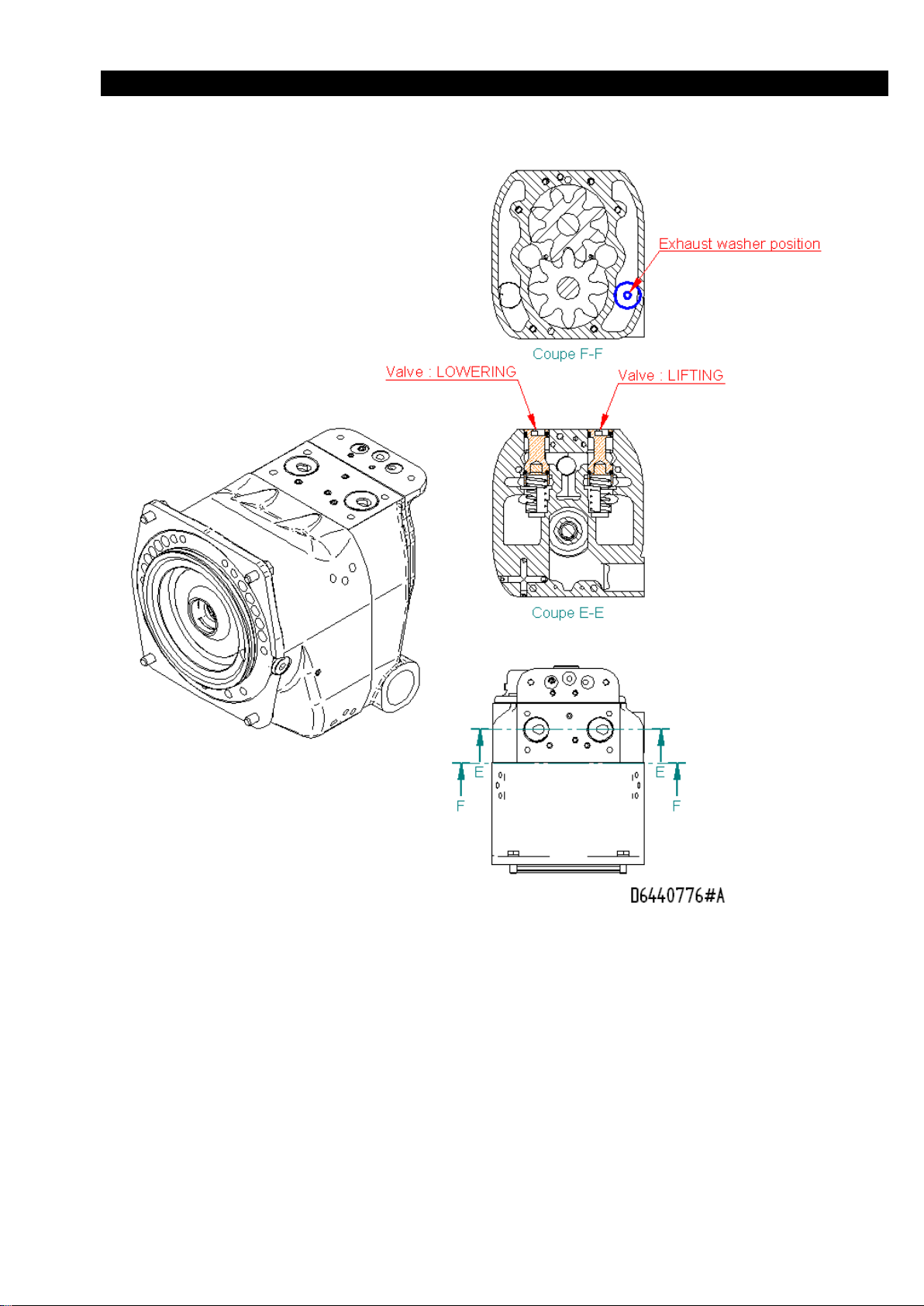
WARNING : Motor Assembly for LC2A015S/LC2A030DIP3LRU…-E
To respect valves position and the exhaust washer position compared with the standard motor (see manual :
MHD56297)
41
Page 42
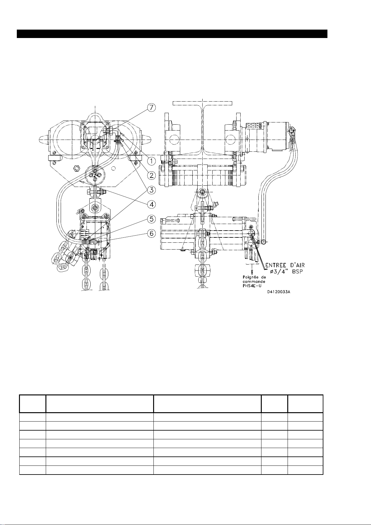
CONNECTION ACCESSORIES ASSEMBLY DRAWING & PARTS LIST
ITEM
NO.
DESIGNATION
PIECE
DESCRIPTION
OF PART
TOTAL
QTY
PART
NO.
1
COUDE UNION 1/2"G
ELBOW
1
6814.4732
2
ABOUT ANNELE 1/2"G
FITTING
1
6163.1832
3
COLLIER DE SERRAGE
CLAMP COLLAR
2
6113.1532
4
FLEXIBLE
HOSE
1
6803.1332
5
ABOUT ANNELE 3/8"G
FITTING
1
6162.3328
6
COUDE M/F 3/8"G
ELBOW
1
6824.1132
7
BOUCHON
PLUG
1
6510.7741
42
Page 43

SINGLE AND DOUBLE FALL BOTTOM HOOK ASSEMBLY DRAWING
Double fall
3 & 6 Ton Hoist
(LC2A015S to 60D)
(Dwg.D4240229)
43
Page 44

SINGLE AND DOUBLE FALL BOTTOM HOOK ASSEMBLY PARTS LIST
Single fall hoists
ITEM
NO.
DESCRIPTION
OF PART
QTY
TOTAL.
PART
NUMBER
1.5 Ton
3 Ton
Standard
Option „R‟
Standard
Option „R‟
721
Pin
1
46001916
722
Retainer ring
1
96090148
723
Ring
1
96090025
96090146
724
Hook block
1
94240293
94240295
725
Ball
11
69401125
726
Plug
1
96090060
727
Grease fitting
1
67102627
67102627
728
Hook
1
94248358
94240294
94248357
94240296
729
Screw
1
41309006
730
Nut
1
58250721
731
Nut
2
58250739
732
Screw CHC M8-45
2
41326206
733
Half bottom block
1 94128393
94128400
734
Thrust bearing
1
54000006
735
Ring 2-pieces
1
94247291
736
Half bottom block
1 94128394
94128401
Double fall hoists
ITEM
NO.
DESCRIPTION
OF PART
QTY
TOTAL.
PART
NUMBER
3 Ton
6 Ton
Standard
Option „R‟
Standard
Option „R‟
740
Screw
3
41326706
41324406
741
Nut
3
43003511
43003611
742
Lockwasher
3
45201008
45201012
743
Bearing
2
50250005
50250006
744
Sprocket wheel
1
94240056
94240263
94120113
94120328
745
Half bottom block
1
94240289
94240297
94120397
94120404
746
Grease fitting
1
67102627
67102627
747
Thrust bearing
1
54000006
54700007
748
Ring 2-pieces
1
94247291
94127398
749
Half bottom block
1
94240288
94240298
94120396
94120403
750
Hook
1
94248357
94240296
94128459
94128402
Recommended Spare
44
Page 45

BOTTOM HOOK ASSEMBLY DRAWING & PARTS LIST LCA060S
Rep
Désignation
Description
Qté.
CODE
Item
Qty.
STANDARD
OPTION „R‟
1
CROCHET 6T
6T HOOK
1
9.412.0395
9.412.0402
2
½ SUPPORT CROCHET(+gr.)
½ HOOK SUPPORT
1
9.526.0138
9.526.0144
3
½ SUPPORT CROCHET
½ HOOK SUPPORT
1
9.526.0139
9.526.0143
4
BAGUE EPAULEE(en 2
SHOULDERED RING
1
9.412. 0398
5
BUTEE
STOP
1
5.470.0007
6
GRAISSEUR
GREASER
1
6.710.2627
7
VIS CHC
SCREW
2
4.133.0006
8
ECROU
NUT
2
4.300.6911
9
RONDELLE FREIN
LOCKWASHER
2
4.520.1010
10
VIS CHC
SCREW
1
9.526.0037
11
ECROU
NUT
1
4.300.4011
12
RONDELLE FREIN
LOCKWASHER
1
4.520.1020
45
Page 46

BOTTOM HOOK ASSEMBLY DRAWING & PARTS LIST LCA070D
Rep
Désignation
Description
Qté.
CODE
Item
Qty.
STANDARD
1
CROCHET
HOOK 1 9.412.0575
2
FLASQUE DE MOUFLE(+gr.)
BOTTOM BLOCK FLANGE
1
9.412.0574
3
FLASQUE DE MOUFLE
BOTTOM BLOCK FLANGE
1
9.412.0573
4
NOIX DE CHAINE
CHAIN SPROCKET WHEEL
1
9.412.0113
5
ROULEMENT A BILLES
BALL BEARING
2
5.025.0006
6
BAGUE EPAULE (2PIECES)
SHOULDERED RING
1
9.412.0398
7
BUTEE
STOP 1 5.470.0007
8
RONDELLE W12
LOCKWASCHER
3
4.520.1012
9
GRAISSEUR
GREASER 1 6.710.2627
10
VIS
SCREW 3 4.132.4406
11
ECROU
NUT 3 4.300. 3611
46
Page 47
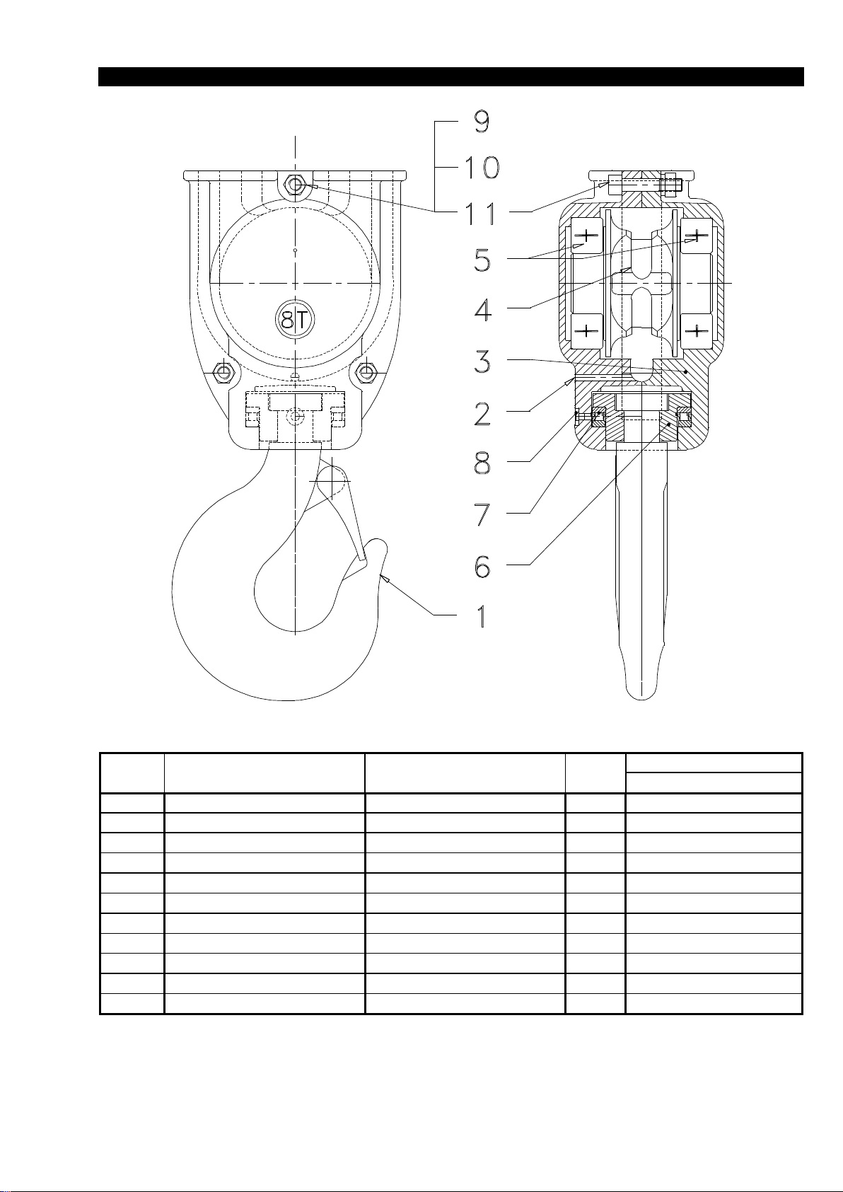
BOTTOM HOOK ASSEMBLY DRAWING & PARTS LIST LCA080D
Rep
Désignation
Description
Qté.
CODE
Item
Qty.
STANDARD
1
CROCHET
HOOK
1
9.623.8234
2
FLASQUE DE MOUFLE(+gr.)
BOTTOM BLOCK FLANGE
1
9.526.0287
3
FLASQUE DE MOUFLE
BOTTOM BLOCK FLANGE
1
9.526.0286
4
NOIX DE CHAINE
CHAIN SPROCKET WHEEL
1
9.526.8006
5
ROULEMENT A BILLES
BALL BEARING
2
5.025.0011
6
BAGUE EPAULE (2PIECES)
SHOULDERED RING
1
9.623.0014
7
BUTEE
STOP
1
5.470.0013
8
GRAISSEUR
GREASER
1
6.710.0827
9
RONDELLE W12
LOCKWASCHER
3
4.520.1012
10
VIS
SCREW
3
4.131.0306
11
ECROU
NUT
3
4.300.3611
47
Page 48

BOTTOM HOOK ASSEMBLY DRAWING & PARTS LIST LCA120D
Item
Description
Qty.
Part number
No.
Of part
total
STANDARD
OPTION „R‟
1
12T HOOK
1
9.623.8234
9.623.0168
2
BOTTOM BLOCK FLANGE
1
9.526.0136
9.526.0142
3
BOTTOM BLOCK FLANGE
1
9.526.0137
9.526.0141
4
CHAIN SPROCKET WHEEL
1
9.526.0006
9.526.0104
5
BALL BEARING
2
5.025.0011
6
SHOULDERED RING
1
9.623.0014
7
STOP
1
5.470.0013
8
GREASER
1
6.7100827
9
SCREW
3
4.132.3106
10
NUT
3
4.300.3611
11
LOCKWASHER
3
4.520.1012
48
Page 49

BOTTOM HOOK ASSEMBLY DRAWING & PARTS LIST LCA250Q
Rep
Désignation
Description
Qté.
CODE
Item
Qty.
STANDARD
OPTION „R‟
1
Noix de chaine
Sprocket wheel
1
9526-8006
9526-8106
2
Crochet 25T
25T Hook
1
9623-8233
9623-8169
3
Flasque de moufle
Bottom BlockFlange
1
9596-8077
4
Flasque de moufle
Bottom BlockFlange
1
9596-8078
5
Bague épaulée (2 piéces)
Shouldered ring ( 2 parts)
1
9623-7026
6
Graisseur
Greaser 1 6710-0827
7
Roulement à billes
Ball Bearing 4 5025-0011
8
Butée à rouleaux
Thrust Roller Bearing
1
5470-0018
9
Vis CHC M20
Screw 3 4132-3906
10
Ecrou H M20
Nut 3 4300-0811
4300-4011
11
Rondelle W20
Split Washer
3
4520-0020
4520-1020
49
Page 50

CHAIN CONTAINER ASSEMBLY DRAWING & PARTS LIST LC2A015S/030D OPTION B
50
Page 51
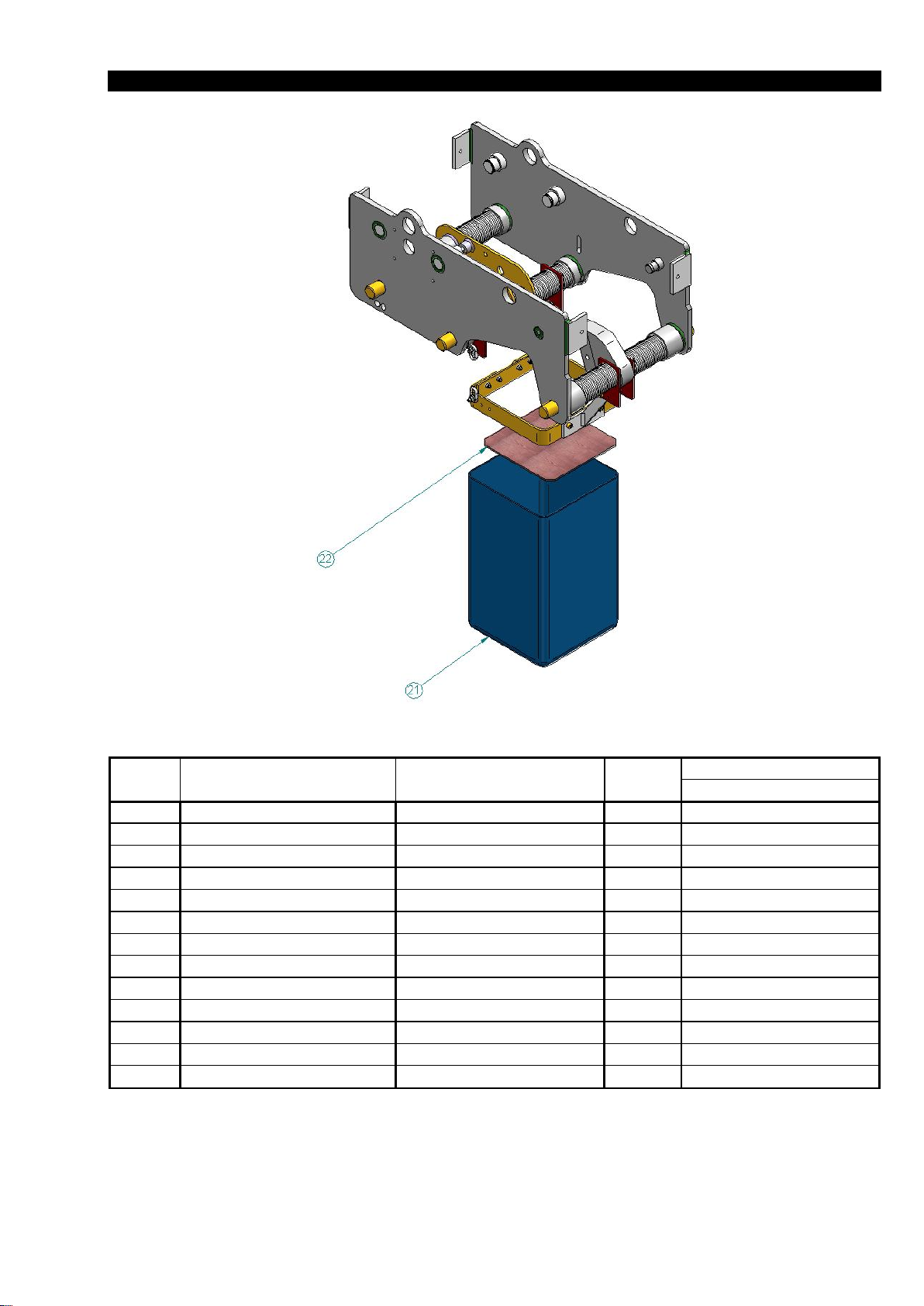
CHAIN CONTAINER ASSEMBLY DRAWING & PARTS LIST LC2A015S/030D OPTION B
Rep
Désignation
Description
Qté.
CODE
Item
Qty.
8
Patte de fixation
Bracket
4
96440589
10
Vis CHC M06x55
Screw
1
41332206
11
Ecrou frein M06
Lock Nut
9
43707611
12
Support bac à chaine
Chain Container Support
1
96440600
13
Support
Support
1
94120179
15
Rondelle plate LL6
Flat washer
6
45701006
16
Vis CHC M06x25
Screw
4
41312206
17
Vis CHC M08x20
Screw
2
41321806
18
Ecrou frein M08
Locknut
2
43706511
19
Plat
Flat
1
96440680
20
Vis CHC M06x20
Screw
4
41322206
21
Sac
Chain Container
1
94120177
22
Plaque de sac
Chain Container Flat
1
94120201
51
Page 52

CHAIN CONTAINER ASSEMBLY DRAWING & PARTS LIST LC2A015S OPTION A
52
Page 53

CHAIN CONTAINER ASSEMBLY DRAWING & PARTS LIST LCA030S/060D/070D
53
Page 54

CHAIN CONTAINER ASSEMBLY DRAWING & PARTS LIST LCA060S TO LCA250Q
Rep
Désignation
Description
Qté.
CODE
Item
Qty.
1
BAC A CHAINE (12m)
CHAIN CONTAINER
1
95260056
2
PLAQUE
PLATE
1
95260057
3
GUIDE CHAINE
CHAIN GUIDE
1
95260171
4
SUPPORT DE BAC
SUPPORT BASKET
1
95260054
5
VIS
SCREW
8
41322206
6
RONDELLE M6
WASHER
12
45001106
7
ECROU FREIN
LOCKNUT
8
43707611
8
CHAINE (4x5maillons)
CHAIN
0.485m
69029232
9
VIS CHc
SCREW
4
41324306
54
Page 55

(OPTION B)CHAIN CONTAINER ASSEMBLY DRAWING & PARTS LIST
101
106
105
107
100
102
104
109
113
111
110
112
108
108
103
Rep
Désignation
Description
Qté.
CODE
Item
Qty.
100
Attache
1
95960131
101
Rondelle élastique W10
Lock Washer
2
45201010
102
Axe d’articulation
Axle
2
95960132
103
Bac à chaine
Chain container
1
95260162
104
Rondelle élastique W6
Lock Washer
2
45201006
105
Vis CHC M6x30
Screw
2
41322306
106
Rondelle élastique W8
Lock Washer
3
45201008
107
Vis CHC M08x25
Screw
2
41324906
108
Vis CHC M08x40
Screw
2
41326706
109
Chaine
Chain
69089432
110
Rondelle plate LL8
Flat washer
1
45701008
111
Ecrou H M8
Nut
1
43003511
112
Rondelle plate M8
Flat washer
1
45701108
113
Ecrou frein M8
Lock Nut
1
43706511
LCA180T TO LCA250Q
55
Page 56

ROPE CONTROL ASSEMBLY DRAWING LCA030S to LCA120D
Rep
Désignation
Description
Qté.
CODE
Item
Qty.
1
CIRCLIPS
CIRCLIPS
1
47700025
2
CLAVETTE
KEY
1
95230029
3
VIS CHC
SCREW
3
41323506
4
RONDELLE FREIN
LOCKWASHER
3
45201010
5
PALIER
BEARING
1
95230027
6
BAGUE AUTO-LUBRIFIANTE
SELF-LUBRIFICATING RING
2
59104926
7
VOLANT DE MANŒUVRE
WHEEL
1
95230028
8
CHAINE DE MANŒUVRE
CHAIN
M
69029232
9
TIGE FILETEE
SCREW ROD
1
95230118
10
BAGUE ENTRETOISE
DISTANCE WASHER
1
95230117
11
PIGNON
PINION
1
95230116
12
ECROU
NUT
2
43003611
56
Page 57

PARTS ORDERING INFORMATION
NOTICE
NOTICE
The use of replacement parts other than INGERSOLLRAND Material Handling will invalidate the Company's
warranty. For prompt service and genuine INGERSOLLRAND Material Handling parts, provide your nearest
Distributor with the following :
1. Complete model number and serial number as it
appears on the nameplate.
2. Part number and part description as shown in this
manual.
3. Quantity required.
For your convenience and future reference it is
recommended that the following information be recorded.
Hoist Model Number ......................................................
Hoist Serial Number .....................................................
Date Purchased .............................................................
Return Goods Policy
INGERSOLL-RAND will not accept returned goods for
warranty or service unless prior arrangements have been
made and written authorization has been provided from the
location the goods were purchased.
Continuing improvement and advancement of design
may cause changes to this trolley which are not
included in this manual. Manuals are periodically
revised to incorporate changes. Always check the
manual edition number on the front cover for the
latest issue.
When the life of the trolley has expired, it is recommended
that the trolley be disassembled, degreased and parts
separated as to materials so that they may be recycled.
For additional information contact :
INGERSOLL-RAND Material Handling
529, avenue Roger Salengro
59450 Sin-le-Noble - France
Phone : (33) 27-93-08-08
Fax : (33) 27-93-08-00
Mineral based oils are recyclable, however, some oils
such as glycols may be extremely toxic and must be
identified and disposed of at an approved waste or
disposal site in accordance with all local, state and
federal laws and regulations.
57
Page 58

GUARANTEE
See our general conditions of sales mentioned on our
proposal, acknowledgement receipt, invoice.
INGERSOLL-RAND guarantees the equipment sold and
supplied by itself against any defect or flaw in manufacture
or operation under the conditions and within the limits
hereafter.
- the guarantee is only valid if the customer has satisfied the
general obligations of the present contract and, in
particular, of settlement.
- the guarantee is strictly limited to INGERSOLL-RAND
equipment. It does extend to supplies and accessories which
are not of its manufacture.
- the guarantee does not extend to assemblies or machines
in which INGERSOLL-RAND equipement is incorporated
and in particular to the performances of these assemblies or
machines.
- when INGERSOLL-RAND equipment is incorporated
into one or other assembly or machine by the customer, he
alone is responsible for the adaptation, the choice and the
suitability of the INGERSOLL-RAND equipment,
INGERSOLL-RAND's diagrams, surveys and layouts being
given only for guidance, unless there is a special stipulation
in the acceptance of order, defined in the acknowledgment
of receipt.
- INGERSOLL-RAND does not guarantiee components
and accessories it does not sell.
Defects in fitting, adaptation, design, connection and
running of the assembly or part of the assembly put
together by the customer are not covered by the guarantee.
INGERSOLL-RAND equipment and material as well as the
assemblies or machines set up by the customer or by a third
party are assumed to be operated and used under the sole
control of the customer or third party.
- The duration of the guarantee is for 6 months from the
start up of the equipment by the customer. The start up
must be made at the latest three months after dispatch of the
equipment or its being made available.
- INGERSOLL-RAND has the right to demand from its
customer proof of the date of start up.
- The guarantee period is reduced to half if the equipment is
used day and night.
- The lenght of guarantee is neither prolonged nor
interrupted by either amicale or litigous claims by the
customer.
- At the expiry of this period, the guarantee ceases
incontestably.
- The obligations of the INGERSOLL-RAND guarantee
will only come into effect if the customer proves that the
defect or flaw appeared during normal operating conditions
for this type of material, or in the course of normal use as
specified by INGERSOLL-RAND.
- It does not apply in the event of user's mistake,
negligence, imprudence, faultly superintencence or
maintenance, inattention to the instructions or directions for
use of low quality lubricants.
INGERSOLL-RAND liability is disclaimed for all damage
brought about by loss or leaks of oil.
- No guarantee applies either for fortuitous incidents or
force majeure, or for wear, replacements or repairs caused
by normal use of the equipment.
- The guarantee is restricted to reconditioning in
INGERSOLL-RAND's premises at its expense and as soon
as possible the equipment and parts recognized as faulty by
its technical or after sales services, which are sent carriage
paid and packing free, without there being any claim for
damage arising, such as injury to personel, damage to
property other than that covered by the present contract,
loss of possession, of production, commercial detriment or
loss of profit.
- During the guarantee period, the cost of labour for
dismantling and reassembling equipment outside
INGERSOLL-RAND's premises, the cost of moving faulty,
replaced or repaired equipment and the travelling and living
expenses of INGERSOLL-RAND's engineers are covered
exclusively by the customer.
- In order to obtain the advantages of the guarantee, the
customer must advice INGERSOLL-RAND without delay
and in writing of the defects and flaws in his equipment of
which he is complained and furnish proof of their genuine
nature. He must give INGERSOLL-RAND or tis agents or
technicians every facility to verify the defects or flaws and
to put them right.
- The guarantee does not apply if the equipment is returned
to INGERSOLL-RAND in a condition other than in which
it broke down or if the seal has been removed, or if it has
been dismantled, repaired or modified by a third party, or
by the user or the customer.
- After having been duly informed of the defect or flaw in
its equipment, INGERSOLL-RAND will put it right as
quickly as possible, reserving the right, in certain cases, to
modify the whole or part of the equipment so as to meet its
obligations.
- The customer agrees that INGERSOLL-RAND will not
be responsible for damage in the event that the customer
has not fulfilled one or other of the obligations set out
above.
- Parts replaced free of charge remain the property or
INGERSOLL-RAND.
- The guarantee does not apply to wearing parts.
58
Page 59

IMPORTANT NOTICE
It is our policy to promote safe delivery of all orders. This shipment has been thoroughly checked, packed and inspected
before leaving our plant and receipt for it in good condition has been received from the carrier. Any loss or damage which
occurs to this shipment while enroute is not to any action or conduct of the manufacturer.
Visible loss or damage
If any of the goods called for on the billof lading or express receipt are damaged or the quantity is short, do not accept them
until the freight or express agent makes an appropriate notation on your freight bill or express receipt.
Concealed loss or damage
When a shipment has been delivered to you in apparent good condition, but upon opening the crate or container, loss or
damage has taken place while in transit, notify the carrier's agent immediatly.
Damage claims
You must file claims for damage with the carrier. It is the transportation company's responsibility to reimburse you for
repair or replacement of goods damaged in shipment. Claims for loss or damage in shipment must not be deducted from the
INGERSOLL-RAND invoice, nor should payment of INGERSOLL-RAND invoice be with held awaiting adjustment of
such claims as the carrier guarantees safe delivery. You may return products damaged in shipment to us for repair, which
services will be for your account and form your basis for claim against the carrier
59
Page 60

United States Office Locations International
For Order Entry and
Order Status :
Ingersoll-Rand
Distribution Center
P.O. Box 618
510 Hester Drive
White House, TN 37188
Phone: (615) 672-0321
Telex: 786573
Fax: (615) 672-0801
For Technical Support:
Ingersoll-Rand
Material Handling
P.O. Box 24046
2724 Sixth Avenue South
Seattle, WA 98124-0046
Phone: (206) 624-0466
Telex: 328795
Fax: (206) 624-6265
Printed in Sin-leNoble(France)
Regional Sales Offices
Atlanta, GA
111 Ingersoll-Rand Drive
Chamblee, GA 30341
Phone: (404) 936-6230
Detroit, MI
23192 Commerce Drive
Farmington Hills, MI 48335
Phone: (313) 476-6677
Fax: (313) 476-6670
Houston, TX
Suite 150
2500 East T.C. Jester
Houston, TX 77008
Phone: (713) 864-3700
Los Angeles, CA
5533 East Olympic Blvd.
Los Angeles, CA 90022
Phone: (213) 725-2826
Milwaukee, WI
12311 W Silver Sping Dr.
Milwaukee, WI 53225
Phone: (414) 461-0973
Philadelphia, PA
P.O. Box 425
900E. 8th Ave., Suite 103
King of Prussia, PA 19406
Phone: (215) 337-5930
Offices and distributors in
principal cities throughout
the world. Contact the
nearest Ingersoll-Rand
office for the name and
address of the distributor in
your country or write/fax
to:
Ingersoll-Rand
Material Handling
P.O. Box 24046
2724 Sixth Avenue South
Seattle, WA 98124-0046
USA
Phone: (206) 624-0466
Telex: 328795
Fax: (206) 624-6265
Canada
National Sales Office
Regional Warehouse
Toronto, Ontario
51 Worcester Road
Rexdale, Ontario
M9W 4K2
Phone: (416) 675-5611
Fax: (416) 675-6920
Order Desk
Fax: (416) 674-6549
Regional Sales Offices
Calgary, Alberta
333 11th Avenue S.W.
Calgary, Abberta
T2R 0C7
Phone: (403) 261-8652
Edmonton, Alberta
1340 Weber Center
5555 Calgary Trail N.W.
Edmonton, Alberta
T6H 5G8
Phone: (403) 438-5039
Fax: (403) 437-3145
Montreal, Quebec
3501 St. Charles Blvd.
Kirkland, Quebec
H9H 4S3
Phone: (514) 695-9040
Fax: (514) 695-0963
British Columbia
201-6351 Westminster Hwy
Richmond, B.C.
V7C 5C7
Phone: (604) 278-0459
Fax: (604) 278-2519
Latin America Operations
Ingersoll-Rand
Production Equipment
Group
730 N.W. 107 Avenue
Suite 300, Miami, FL
33172-3107
Phone: (305) 559-0500
Telex: 441617TLS UI
Fax: (305) 559-7505
Europe, Middle East and
Africa
Ingersoll-Rand Equipements
de Production S.A.
529, avenue Roger Salengro
59450 Sin le Noble, France
Phone: (33) 27.93.08.08
Fax: (33) 27.93.08.00
Asia - Pacific Operations
Ingersoll-Rand (Japan) Ltd.
Kowa Bldg. No. 17
2-7 Nishi-Azabu 1-chome
Minato-ku, Tokyo 106,
Japan
Phone: (03) 3403-0641/7
Fax: 81 3 3401-2049
Russia
Ingersoll-Rand Company
World Trade Center
Office 1101
Krasnopresnenskaya
Nab.12
Moscow, Russia 123610
60
 Loading...