

Ingersoll-Rand LA422-EU, LA421-EU Product Information
Air Angle Grinder
Models LA421-EU and LA422-EU
Product Information
45661337
Edition 1
January 2010
EN
Product Information
ES
Especicaciones del producto
FR
Spécications du produit
IT
Speciche prodotto
DE
Technische Produktdaten
NL
Productspecicaties
DA
Produktspecikationer
SV
Produktspecikationer
NO
Produktspesikasjoner
FI
Tuote-erittely
PT
Especicações do Produto
EL
Προδιαγραφές προϊόντος
Save These Instructions
SL
Specikacije izdelka
SK
Špecikácie produktu
CS
Specikace výrobku
ET
Toote spetsikatsioon
HU
A termék jellemzői
LT
Gaminio techniniai duomenys
LV
Ierices specikacijas
PL
Informacje macje o produkcie
BG
Информация за продукта
RO
Informaţii privind produsul
RU
Технические характеристики изделия
ZH
产品信息
JA
製品仕様
KO
제품 상세
4
7
5
3
2
1
9
48h
24h
10
8h
8
6
PMAX
1
3
2
5
6
9
10
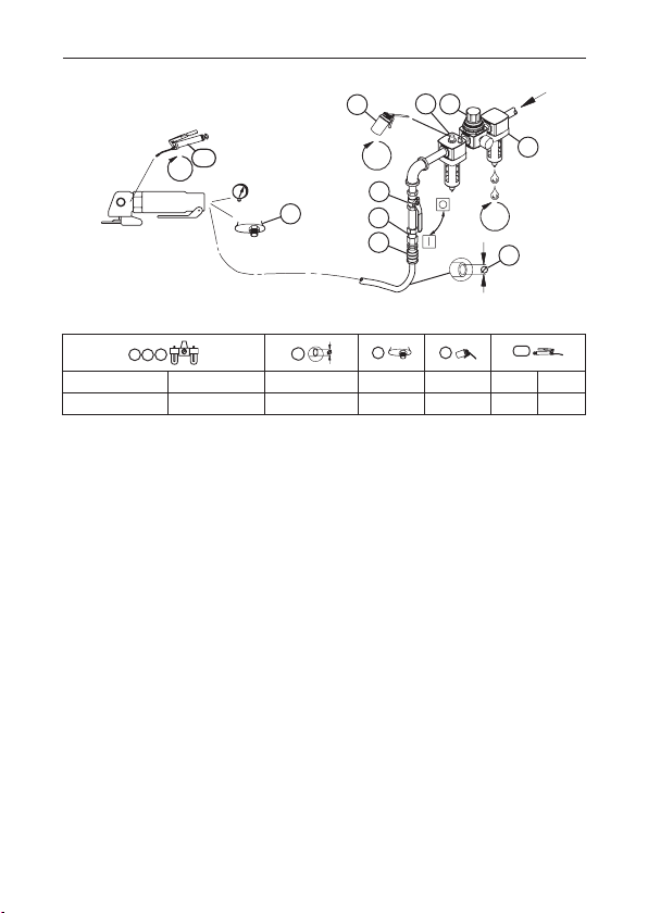
(Dwg. 16616807)
IR # - NPT IR # - BS inch (mm) NPT IR # IR # cm
C38121-600 C381B1-600 3/8 (10) 1/4 50 67 2
2 45661337_ed1
3
EN
Product Safety Information
Intended Use:
These Air Grinders are designed for material removal or cutting o using a rotated abrasive wheel,
in accordance with the product specication table.
For additional information refer to Product Safety Information Manual Form 04584959.
Manuals can be downloaded from www.ingersollrandproducts.com.
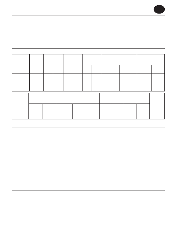
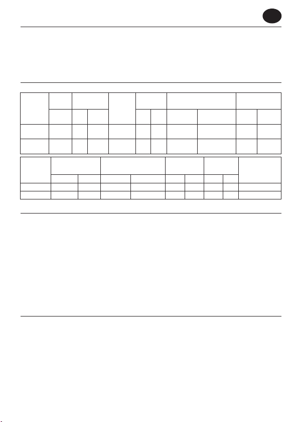
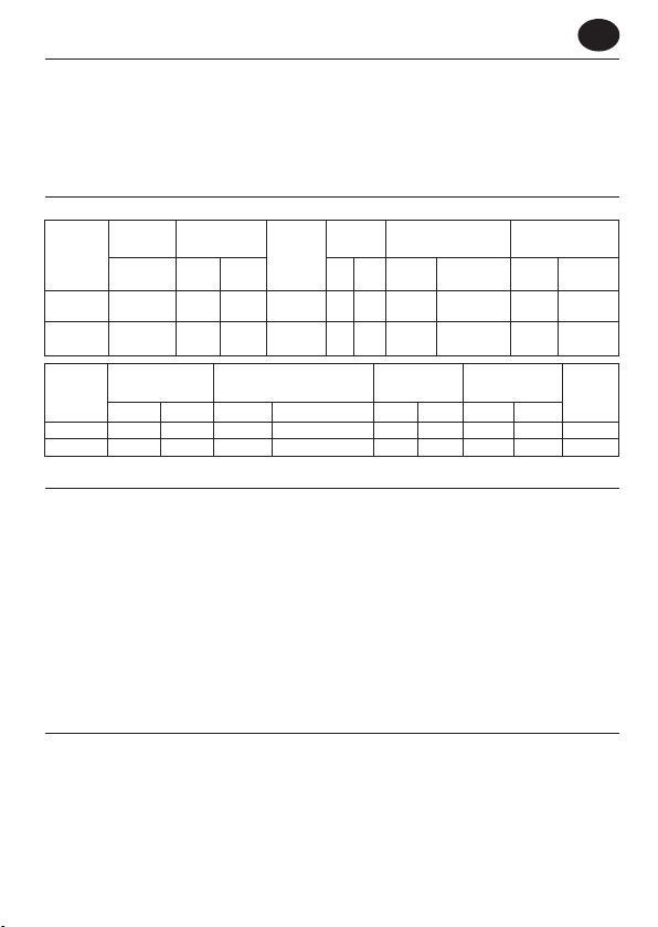
Product Specications
Free
Wheel
Speed
Models
LA421-EU 12000 4 102
LA422-EU 12000 5 127
Models
LA421-EU 6 170 25 708 3.8 1.72 8.9 226 Front
LA422-EU 6 170 25 708 3.8 1.72 8.9 226 Front
* K = Vibration measurement uncertainty
Capacity
rpm inch mm hp kW Pressure
Average Air
Consumption
cfm l/min cfm l/min lbs Kg inch mm
Arbor
3/8” - 24
Thread
3/8” - 24
Thread
Air Consumption @ Load Tool Weight Overall Length
Installation and Lubrication
Size air supply line to ensure tool’s maximum operating pressure (PMAX) at tool inlet. Drain condensate
from valve(s) at low point(s) of piping, air lter and compressor tank daily. Install a properly sized Safety
Air Fuse upstream of hose and use an anti-whip device across any hose coupling without internal shuto, to prevent hose whipping if a hose fails or coupling disconnects. See drawing 16616807 and table
on page 2. Maintenance frequency is shown in a circular arrow and dened as h=hours, d=days, and
m=months of actual use. Items identied as:
1. Air lter 7. Coupling
2. Regulator 8. Safety Air Fuse
3. Lubricator 9. Oil
4. Emergency shut-o valve 10. Grease
5. Hose diameter
6. Thread size
Parts and Maintenance
When the life of the tool has expired, it is recommended that the tool be disassembled,
degreased and parts be separated by material so that they can be recycled.
The original language of this manual is English.
Tool repair and maintenance should only be carried out by an authorized Service Center.
Refer all communications to the nearest Ingersoll Rand Oce or Distributor.
Rated
Power
1.0 0.75 85.6 98.6 4.8 1.4
1.0 0.75 85.6 98.6 6.0 2.1
Sound Level dB (A)
(ANSI S5.1-1971)
(ISO3744)
Power
Vibration (m/s2)
(ISO28927)
Level *K
Exhaust
45661337_ed1 EN-1
ES
Información de Seguridad sobre el Producto
Uso Indicado:
Estas amoladoras neumáticas están diseñadas para eliminar material mediante un accesorio
rotatorio, de acuerdo con la tabla de especicaciones del producto.
Para obtener más información, consulte el formulario 04584959 del manual de información de
seguridad del producto.
Los manuales pueden descargarse en www.ingersollrandproducts.com.
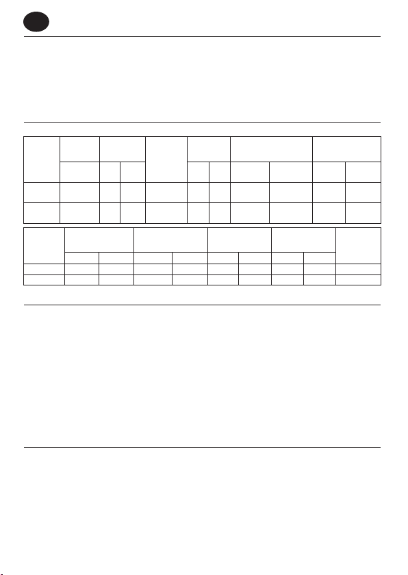
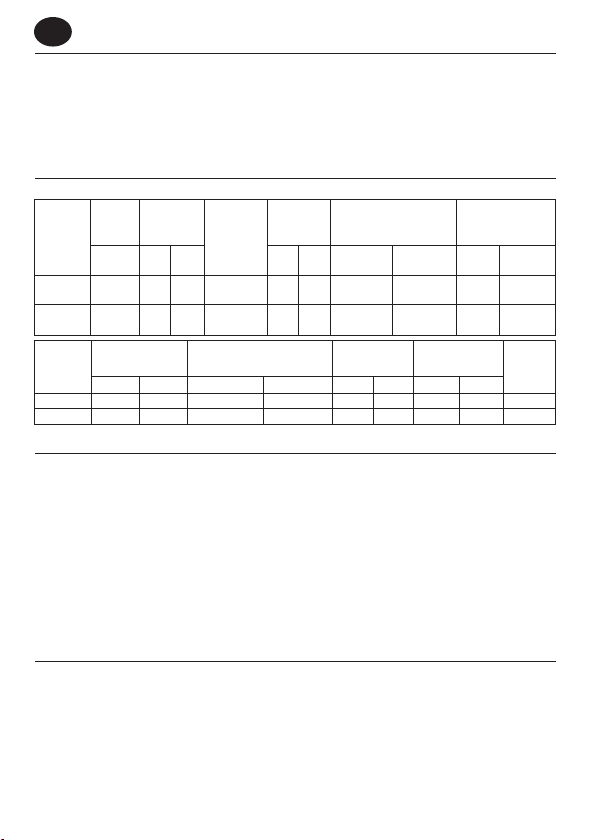
Especicaciones del Producto
Velocidad
Modelos
LA421-EU 12000 4 102
LA422-EU 12000 5 127
Modelos
LA421-EU 6 170 25 708 3.8 1.72 8.9 226 Frente
LA422-EU 6 170 25 708 3.8 1.72 8.9 226 Frente
* K = de error (Vibración)
Instalación y Lubricación
Diseñe la línea de suministro de aire para asegurar la máxima presión de funcionamiento (PMAX) en la
entrada de la herramienta. Vacíe el condensado de las válvulas en los puntos inferiores de la tubería,
ltro de aire y depósito del compresor de forma diaria. Instale una contracorriente de manguera de fusil
de aire de seguridad de tamaño adecuado y utilice un dispositivo antilatigazos en cualquier acoplamiento de manguera sin apagador interno para evitar que las mangueras den latigazos en caso de que una
manguera falle o de que el acoplamiento se desconecte. Consulte la dibujo 16616807 y la tabla en la
página 2. La frecuencia de mantenimiento se muestra dentro de una echa circular y se dene como h =
horas, d = días y m = meses de uso real. Los elementos se identican como:
1. Filtro de aire 5. Diámetro de la manguera 9. Aceite
2. Regulador 6. Tamaño de la rosca 10. Grasa
3. Lubricador 7. Acoplamiento
4. Válvula de corte de emergencia 8. Fusil de aire de seguridad
Piezas y Mantenimiento
Una vez vencida la vida útil de herramienta, se recomienda desarmar la herramienta, desengrasarla y
separar las piezas de acuerdo con el material del que están fabricadas para reciclarlas.
El idioma original de este manual es el inglés.
Las labores de reparación y mantenimiento de las herramientas sólo puede ser realizadas por un Centro
de Servicio Autorizado.
Toda comunicación se deberá dirigir a la ocina o al distribuidor Ingersoll Rand más próximo.
Capacidad
Libre
de la Muela
rpm inch mm hp kW Presión
Consumo Medio
de Aire
cfm l/min cfm l/min lbs Kg inch mm
Consumo Medio
Según Carga
Potencia
Nominal
Pérgola
3/8” - 24
1.0 0.75 85.6 98.6 4.8 1.4
Rosca
3/8” - 24
1.0 0.75 85.6 98.6 6.0 2.1
Rosca
Nivel Sonoro dB(A)
(ANSI S5.1-1971)
Peso de la
Herramienta
Potencia
(ISO3744)
Longitud General
Vibración (m/s²)
(ISO28927)
Nivel *K
Emisiones
de Escape
ES-1 45661337_ed1
FR
Informations de Sécurité du Produit
Utilisation Prévue:
Ces meuleuses pneumatiques sont conçues pour enlever de la matière ou eectuer des découpes
à l’aide d’un disque abrasif rotatif, conformément au tableau des spécications de produit.
Pour en savoir plus, consultez le manuel 04584959 relatif aux informations de sécurité du produit.
Les manuels peuvent être téléchargés à l’adresse www.ingersollrandproducts.com.
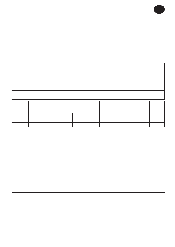
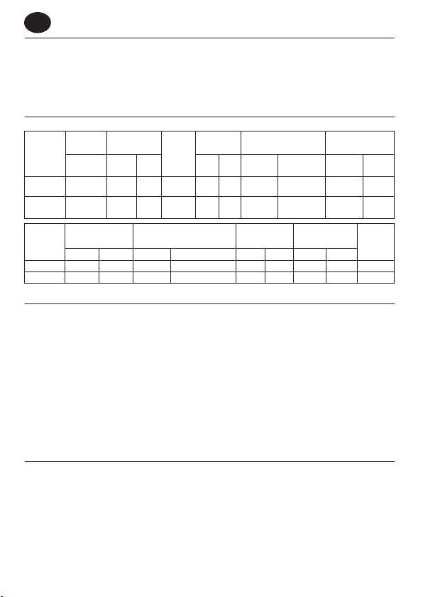
Spécications du Produit
* K = incertitude de mesure (Vibration)
Installation et Lubrication
Dimensionnez l’alimentation en air de façon à obtenir une pression maximale (PMAX) au niveau de
l’entrée d’air de l’outil. Drainez quotidiennement le condensat des vannes situées aux points bas de la
tuyauterie, du ltre à air et du réservoir du compresseur. Installez un raccordement à air de sûreté dont la
taille est adaptée au tuyau et placez-le en amont de celui-ci, puis utilisez un dispositif anti-débattement
sur tous les raccords pour tuyaux sans fermeture interne, an d’empêcher les tuyaux de fouetter si l’un
d’entre eux se décroche ou si le raccord se détache. Reportez-vous à l’illustration 16616807 et au tableau
de la page 2. La fréquence des opérations d’entretien est indiquée dans la èche circulaire et est dénie
en h=heures, d=jours, et m=mois de fonctionnement. Eléments identiés en tant que:
1. Filtre à air 5. Diamètre du tuyau 9. Huile
2. Régulateur 6. Taille du letage 10. Graisse
3. Lubricateur 7. Raccord
4. Vanne d’arrêt d’urgence 8. Raccordement à air de sûreté
Pièces Détachées et Maintenance
A la n de sa durée de vie, il est recommandé de démonter l’outil, de dégraisser les pièces et de les
séparer en fonction des matériaux de manière à ce que ces derniers puissent être recyclés.
Ce manuel a été initialement rédigé en anglais.
La réparation et la maintenance des outils ne devraient être réalisées que par un centre de services autorisé.
Adressez toutes vos communications au Bureau Ingersoll Rand ou distributeur le plus proche.
Vitesse
Capacité du
Libre
Modèles
LA421-EU 12000 4 102
LA422-EU 12000 5 127
Modèles
LA421-EU 6 170 25 708 3.8 1.72 8.9 226 Avant
LA422-EU 6 170 25 708 3.8 1.72 8.9 226 Avant
Disque
rpm inch mm hp kW Pression
Consommation
Moyenne en Air
cfm l/min cfm l/min lbs Kg inch mm
Consommation D’air
Puissance
Nominale
Arbre
3/8” - 24
Filetage
3/8” - 24
Filetage
Avec une Charge
Niveau Acoustique dB(A)
(ANSI S5.1-1971)
Puissance
(ISO3744)
1.0 0.75 85.6 98.6 4.8 1.4
1.0 0.75 85.6 98.6 6.0 2.1
Poids de
L’outil
Longueur
Totale
Vibration (m/s²)
(ISO28927)
Niveau *K
Échappement
45661337_ed1 FR-1
IT
Informazioni sulla Sicurezza del Prodotto
Destinazione D’uso:
Queste smerigliatrici pneumatiche sono progettate per rimuovere e ritagliare il materiale tramite un
accessorio abrasivo rotante, secondo la tabella contenente le speciche del prodotto.
Per ulteriori informazioni, consultare il modulo 04584959 nel Manuale di informazioni sulla
sicurezza del prodotto.
I manuali possono essere scaricati da internet al sito www.ingersollrandproducts.com.
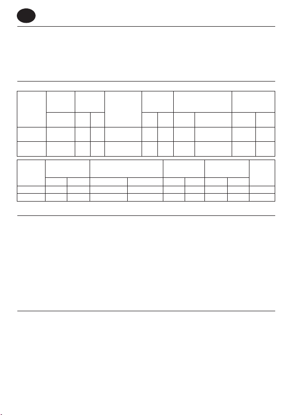
Speciche Prodotto
Velocità
Capacità
a Vuoto
Modelli
LA421-EU 12000 4 102
LA422-EU 12000 5 127
Consumo Medio
Modelli
LA421-EU 6 170 25 708 3.8 1.72 8.9 226 Anteriore
LA422-EU 6 170 25 708 3.8 1.72 8.9 226 Anteriore
* K = incertezza misurazione (Vibrazioni)
Mola
Mandrino
rpm inch mm hp kW Pressione
3/8” - 24
Filettatura
3/8” - 24
Filettatura
di Aria
cfm l/min cfm l/min lbs Kg inch mm
Consumo Medio di Aria
Installazione e Lubricazione
La linea di alimentazione dell’aria deve essere dimensionata in maniera tale da assicurare all’utensile la
massima pressione di esercizio (PMAX) in ingresso. Scaricare quotidianamente la condensa dalla valvola
o dalle valvole sulla parte bassa della tubatura, dal ltro dell’aria e dal serbatoio del compressore. Installare un fusibile di sicurezza di dimensioni adatte a monte del tubo essibile e utilizzare un dispositivo
antivibrazioni su tutti i manicotti senza arresto interno per evitare i colpi di frusta dei essibili, se questi
si guastano o se si staccano gli accoppiamenti. Vedere il disegno 16616807 e la tabella a pagina 2. La
frequenza di manutenzione viene illustrata da una freccia circolare e denita con h=ore, d=giorni (days)
e m=mesi di uso eettivo. Componenti:
1. Filtro aria 5. Diametro tubo essibile 9. Olio
2. Regolatore 6.
3. Lubricatore 7. Accoppiamento
4.
Valvola di arresto di emergenza
8. Fusibile di sicurezza
Ricambi e Manutenzione
Quando l’attrezzo diventato inutilizzabile, si raccomanda di smontarlo, sgrassarlo e separare i
componenti secondo i materiali in modo da poterli riciclare.
La lingua originale di questo manuale è l’inglese.
Riparazioni e manutenzione degli utensili devono essere eseguite esclusivamente da un Centro di
Assistenza Autorizzato.
Indirizzare tutte le comunicazioni al più vicino concessionario od ucio Ingersoll Rand.
IT-1 45661337_ed1
Potenza
Nominale
1.0 0.75 85.6 98.6 4.8 1.4
1.0 0.75 85.6 98.6 6.0 2.1
a Carico
Dimensione della lettatura
Livello Acustico dB(A)
(ANSI S5.1-1971)
Potenza
(ISO3744)
Peso
Dell’attrezzo
10.
Ingrassaggio
Vibrazioni (m/s²)
Livello *K
Lunghezza
Complessiva
(ISO28927)
Scarico
DE
Hinweise zur Produktsicherheit
Vorgesehene Verwendung:
Diese Druckluft-Schleifmaschinen wurden dazu entwickelt, in Übereinstimmung mit der ProduktSpezikationstabelle mit einem sich drehenden Schleifmittel Material zu entfernen oder abzuschneiden.
Für zusätzliche Informationen siehe das Formblatt 04584959. im Handbuch Produktsicherheitsinformationen.
Handbücher können von www.ingersollrandproducts.com heruntergeladen werden.
Technische Produktdaten
Nenndreh-
Modelle
LA421-EU 12000 4 102
LA422-EU 12000 5 127
Modelle
LA421-EU 6 170 25 708 3.8 1.72 8.9 226 Vordere
LA422-EU 6 170 25 708 3.8 1.72 8.9 226 Vordere
* K = Messunsicherheit (Schwingungs)
Montage und Schmierung
Druckluftzufuhrleitung an der Druckluftzufuhr des Werkzeugs gemäß des maximalen Betriebsdrucks
(PMAX) bemessen. Kondensat an den Ventilen an Tiefpunkten von Leitungen, Luftlter und Kompressortank täglich ablassen. Eine Sicherheits- Druckluftsicherung gegen die Strömungsrichtung im Schlauch
und eine Anti- Schlagvorrichtung an jeder Verbindung ohne interne Sperre installieren, um ein Peitschen
des Schlauchs zu verhindern, wenn ein Schlauch fehlerhaft ist oder sich eine Verbindung löst. Siehe
Zeichnung 16616807 und Tabelle auf Seite 2. Die Wartungshäugkeit mit einem Pfeil eingekreist und ist
deniert in h=Stunden, d=Tagen und m=Monaten der tatsächlichen Verwendung. Teile:
1. Luftlter 5. Schlauchdurchmesser 9. Ölen
2. Regler 6. Gewindegröße 10.Fetten
3. Schmierbüchse 7. Verbindung
4. Notabsperrventil 8. Sicherheits-Druckluftsicherung
Teile und Wartung
Zur Entsorgung ist das Werkzeug vollständig zu demontieren, zu entfetten und nach Materialarten
getrennt der Wiederverwertung zuzuführen.
Die Originalsprache dieses Handbuchs ist Englisch.
Die Werkzeug-Reparatur und -Wartung darf nur von einem autorisierten Wartungszentrum durchgeführt
werden.
Wenden Sie sich bei Rückfragen an Ihre nächste Ingersoll Rand Niederlassung oder den autorisierten
Fachhandel.
45661337_ed1 DE-1
Scheiben-
zahl
größe
rpm inch mm hp kW Druck
Durchschnittli-
cher Luftver-
brauch
cfm l/min cfm l/min lbs Kg inch mm
Luftverbrauch zu Last
Nennleis-
Dorn
3/8” - 24
1.0 0.75 85.6 98.6 4.8 1.4
Gewinde
3/8” - 24
1.0 0.75 85.6 98.6 6.0 2.1
Gewinde
tung
Schallpegel dB(A)
(ANSI S5.1-1971)
Stromzufuhr
(ISO3744)
Werkzeugge-
wicht
Schwingungs (m/s²)
Level *K
Gesamtlänge
(ISO28927)
Abluft
NL
Productveiligheidsinformatie
Bedoeld Gebruik:
Deze pneumatische slijpmachines zijn bedoeld om materiaal te verwijderen of weg te snijden met
behulp van een roterende slijpschijf, overeenkomstig de productspecicatietabel.
Zie formulier 04584959 van de productveiligheidshandleiding voor aanvullende informatie.
Handleidingen kunnen worden gedownload vanaf www.ingersollrandproducts.com.
Produktspesikasjoner
Onbelast
Toerental
Modellen
LA421-EU 12000 4 102
LA422-EU 12000 5 127
Modellen
LA421-EU 6 170 25 708 3.8 1.72 8.9 226 Voorste
LA422-EU 6 170 25 708 3.8 1.72 8.9 226 Voorste
* Meetonnauwkeurigheid bij K (Trillings)
Schijfca-
paciteit
rpm inch mm hp kW Druk
Gemiddeld
Luchtverbruik
cfm l/min cfm l/min lbs Kg inch mm
Cilinder
3/8” - 24
Schroefdraad
3/8” - 24
Schroefdraad
Luchtverbruik en Belasting
Installatie en Smering
Om de maximale bedrijfsdruk ( Pmax) bij de luchtinlaat van het toestel te garanderen, moet de luchttoevoerleiding hierop geselecteerd zijn. Tap dagelijks condensaat af van kleppen bij lage punten van
het leidingwerk, de luchtlter en de compressortank. Monteer een beveiliging met de juiste afmeting
bovenstrooms van de slang en gebruik een antislingerinrichting op elke slangkoppeling zonder interne
afsluiter om te voorkomen dat de slang gaat slingeren als een slang valt of een koppeling losraakt. Zie
tekening 16616807 en tabel op pagina 2. De onderhoudsfrequentie wordt weergegeven in een cirkelvormige pijl met h=uren, d=dagen en m=maanden reëel gebruik. Aangegeven onderdelen:
1. Luchtlter 5. Slangdiameter 9. Olie
2. Regelaar 6. Soort van schroefdraad 10. Smeervet
3. Smeerinrichting 7. Koppeling
4. Noodafsluitklep 8. Beveiliging
Onderdelen en Onderhoud
Wanneer de levensduur van het gereedschap verstreken is, wordt u aangeraden het gereedschap te
demonteren en ontvetten, en de delen gescheiden naar materialen op te bergen zodat zij gerecycled
kunnen worden.
De oorspronkelijke taal van deze handleiding is Engels.
Reparatie en onderhoud van dit gereedschap mogen uitsluitend door een erkend servicecentrum
worden uitgevoerd.
Richt al uw communicatie tot het dichtsbijzijnde Ingersoll Rand Kantoor ofWederkoper.
Standaard
Vermogen
1.0 0.75 85.6 98.6 4.8 1.4
1.0 0.75 85.6 98.6 6.0 2.1
Geluidsniveau dB(A)
(ANSI S5.1-1971)
Gereedschaps-
gewicht
Vermogen
(ISO3744)
Totale Lengte
Trillings (m/s²)
(ISO28927)
Niveau *K
Uitlaat
NL-1 45661337_ed1
DA
Produktsikkerhedsinformation
Anvendelsesområder:
Disse trykluftslibemaskiner er beregnet til ernelse af materiale eller afskæring med en roterende
slibende skive, i overensstemmelse med produktets specikationstabel.
For yderligere oplysninger henvises der til formular 04584959 i vejledningen med produktsikkerhedsinformation.
Vejledningerne kan hentes ned fra www.ingersollrandproducts.com.
Produktspecikationer
Fri
Hastighed
Modeller
LA421-EU 12000 4 102
LA422-EU 12000 5 127
Gennemsnitligt
Modeller
LA421-EU 6 170 25 708 3.8 1.72 8.9 226 Forside
LA422-EU 6 170 25 708 3.8 1.72 8.9 226 Forside
* K = måleusikkerhed (Vibrations)
Hjulkapacitet
rpm inch mm hp kW Tryk
Luftforbrug
cfm l/min cfm l/min lbs Kg inch mm
Luftforbrug ved Ladning Værktøjsvægt
Installation og Smøring
Sørg for at lufttilførselsledningen har den korrekte størrelse for at sikre maksimalt driftstryk (PMAX) ved
værktøjsindgangen. Tøm dagligt ventilen(-erne) for kondensat ved rørenes, luftlterets og kompressortankens lavpunkt(er). Montér en sikkerhedstryksikring i korrekt størrelse i opadgående slange og
brug en anti-piskeanordning tværs over enhver slangekobling uden intern aukning for at forhindre
at slangen pisker, hvis en slange svigter eller kobling adskilles. Se tegning 16616807 og tabel på side 2.
Vedligeholdelseshyppigheden vises med en rund pil og deneres som t=timer, d=dage og m=måneder
for reel brug. Elementerne er identiceret som:
1. Luftlter 7. Kobling
2. Regulator 8. Sikkerhedstryksikring
3. Smøreapparat 9. Olie
4. Nødafspærringsventil 10. Fedt
5. Slangediameter
6. Gevindstørrelse
Reservedele og Vedligeholdelse
Efter værktøjets levetid anbefales det at demontere og aedte værktøjet, og opdele de adskilte komponenter ud fra materialetypen, så de kan genbruges.
Denne vejlednings originalsprog er engelsk.
Reparationsarbejde og vedligeholdelse må kun udføres af et autoriseret servicecenter.
Al korrespondance bedes stilet til Ingersoll Rands nærmeste kontor eller distributør.
Angivet
Dorn
3/8” - 24
1.0 0.75 85.6 98.6 4.8 1.4
Gevind
3/8” - 24
1.0 0.75 85.6 98.6 6.0 2.1
Gevind
Eekt
Lydniveau dB(A)
(ANSI S5.1-1971)
Eekt
(ISO3744)
Vibrations (m/s²)
(ISO28927)
Niveau *K
Samlede
Længde
Ud-
blæsn-
ing
45661337_ed1 DA-1
SV
Produktsäkerhetsinformation
Avsedd Användning:
Dessa luftdrivna slipmaskiner är utformade för borttagning av material med ett roterande avverkande
tillbehör i enlighet med tabellen för produktspecikationer.
För mer information, se produktsäkerhetsinformation Form 04584959.
Handböcker kan laddas ner från www.ingersollrandproducts.com.
Produktspecikationer
Fri
Modeller
LA421-EU 12000 4 102
LA422-EU 12000 5 127
Modeller
LA421-EU 6 170 25 708 3.8 1.72 8.9 226 Främre
LA422-EU 6 170 25 708 3.8 1.72 8.9 226 Främre
* K = mätosäkerhet (Vibrations)
rpm inch mm hp kW Tryck
Genomsnitt Luft-
förbrukning
cfm l/min cfm l/min lbs Kg inch mm
Luftförbrukning vid
Hjulkapacitet
Hastighet
Dorn
3/8” - 24
Gängor
3/8” - 24
Gängor
Belastning
Märkström
Installation och Smörjning
Dimensionera luftledningen för att säkerställa maximalt driftstryck (PMAX) vid verktygets ingångsanslutning. Dränera dagligen kondens från ventiler placerade vid ledningens lägsta punkter, luftlter och
kompressortank. Installera en säkerhetsventil av lämplig storlek uppström från slangen och använd en
anti-ryckenhet över alla slangkopplingar som saknar intern avstängning, för att motverka att slangen
rycker till och en slang går sönder eller koppling lossar. Se illustrationen 16616807 och tabellen på sidan
2. Underhållsintervallen visas i runda pilar och denieras som h=timmar, d=dagar och m=månader av
faktisk brukstid. Posterna denieras som:
1. Luftlter 7. Koppling
2. Regulator 8. Säkerhetsventil
3. Smörjare 9. Olja
4. Nödstoppsventil 10. Fett
5. Slangdiameter
6. Gängdimension
Delar och Underhåll
Då verktyget är utslitet, rekommenderar vi att det tas isär och avfettas, samt att de olika delarna sorteras
för återvinning.
Det ursprungliga språket för den här handboken är engelska.
Reparation och underhåll av verktygen får endast utföras av ett auktoriserat servicecenter.
Alla förfrågningar bör ske till närmaste Ingersoll Rand kontor eller distributör.
Ljudstyrkenivå dB(A)
(ANSI S5.1-1971)
(ISO3744)
1.0 0.75 85.6 98.6 4.8 1.4
1.0 0.75 85.6 98.6 6.0 2.1
Verktygsvikt Allmän Vikt
Eekt
Vibrations (m/s²)
(ISO28927)
Niva *K
Utblåsn-
ing
SV-1 45661337_ed1
 Loading...