

Ingersoll-Rand SM132, SH90, SH132, SL110, SM150 Installation, Operation And Maintenance Manual
...Page 1
80448574
Revision A
May 2015
Save These Instructions
Oil-Free Rotary Screw Air Compressor
Installation, Operation and Maintenance
SL90, SM90, SH90, SL110, SM110, SH110
SL132, SM132, SH132, SL150, SM150, SH150
SL200, SM200, SH200, SL250, SM250, SH250, SH300
L125, H125, HH125, L150, H150, HH150
L200, H200, HH200, L250, H250, HH250
L300, H300, HH300, L350, H350, HH350, HH400
61115.10.33
Page 2

2 80448574 Rev A
FOREWORD . . . . . . . . . . . . . . . . . . . . . . . . . . . . . . . . . . . . . 4
SAFETY . . . . . . . . . . . . . . . . . . . . . . . . . . . . . . . . . . . . . . . . . 5
GENERAL INFORMATION . . . . . . . . . . . . . . . . . . . . . . . . . 6
GENERAL OPERATION . . . . . . . . . . . . . . . . . . . . . . . . . . . . . . . . . . . . . 6
DESIGN PRESSURES . . . . . . . . . . . . . . . . . . . . . . . . . . . . . . . . . . . . . . .6
DESIGN TEMPERATURES . . . . . . . . . . . . . . . . . . . . . . . . . . . . . . . . . . . 6
COMPRESSED AIR SYSTEM . . . . . . . . . . . . . . . . . . . . . . . . . . . . . . . . .6
CONDENSATE REMOVAL SYSTEM . . . . . . . . . . . . . . . . . . . . . . . . . .6
LUBRICATION SYSTEM . . . . . . . . . . . . . . . . . . . . . . . . . . . . . . . . . . . . .6
COOLING SYSTEM (AIRCOOLED) . . . . . . . . . . . . . . . . . . . . . . . . . . . 7
COOLING SYSTEM (WATERCOOLED) . . . . . . . . . . . . . . . . . . . . . . . .7
ELECTRICAL SYSTEM . . . . . . . . . . . . . . . . . . . . . . . . . . . . . . . . . . . . . .7
CAPACITY CONTROL . . . . . . . . . . . . . . . . . . . . . . . . . . . . . . . . . . . . . . .7
AUTOMATIC START/STOP CONTROL OPTION . . . . . . . . . . . . . . .7
REMOTE LOAD/UNLOAD OPTION . . . . . . . . . . . . . . . . . . . . . . . . . .8
REMOTE START/STOP OPTION . . . . . . . . . . . . . . . . . . . . . . . . . . . . .8
POWER OUTAGE RESTART OPTION . . . . . . . . . . . . . . . . . . . . . . . . .8
SEQUENCER CONTROL . . . . . . . . . . . . . . . . . . . . . . . . . . . . . . . . . . . .8
TIMED LEAD/LAG OPTION . . . . . . . . . . . . . . . . . . . . . . . . . . . . . . . . . 8
SCHEDULED START/STOP OPTION . . . . . . . . . . . . . . . . . . . . . . . . .8
HIGH CONDENSATE LEVEL SWITCH . . . . . . . . . . . . . . . . . . . . . . . . .8
RECEIPT / HANDLING . . . . . . . . . . . . . . . . . . . . . . . . . . . . 9
RECEIPT . . . . . . . . . . . . . . . . . . . . . . . . . . . . . . . . . . . . . . . . . . . . . . . . . . .9
UNPACKING AND HANDLING . . . . . . . . . . . . . . . . . . . . . . . . . . . . . .9
LONG TERM STORAGE . . . . . . . . . . . . . . . . . . . . . . . . . . . . . . . . . . . . .9
INSTALLATION . . . . . . . . . . . . . . . . . . . . . . . . . . . . . . . . . 10
LOCATION IN THE PLANT . . . . . . . . . . . . . . . . . . . . . . . . . . . . . . . . 10
DISCHARGE AND CONDENSATE PIPING . . . . . . . . . . . . . . . . . . 10
PRIOR TO STARTING . . . . . . . . . . . . . . . . . . . . . . . . . . . . . . . . . . . . . 11
ELECTRICAL CONNECTION . . . . . . . . . . . . . . . . . . . . . . . . . . . . . . . 11
COOLING WATER PIPING . . . . . . . . . . . . . . . . . . . . . . . . . . . . . . . . . 11
VENTING THE WATER SYSTEM . . . . . . . . . . . . . . . . . . . . . . . . . . . . 11
DRAINING THE WATER SYSTEM . . . . . . . . . . . . . . . . . . . . . . . . . . . 12
WATER QUALITY RECOMMENDATIONS . . . . . . . . . . . . . . . . . . . 12
ROTATION CHECK . . . . . . . . . . . . . . . . . . . . . . . . . . . . . . . . . . . . . . . 12
DRIVE MOTOR . . . . . . . . . . . . . . . . . . . . . . . . . . . . . . . . . . . . . . . . . . . 12
FAN MOTOR . . . . . . . . . . . . . . . . . . . . . . . . . . . . . . . . . . . . . . . . . . . . . 13
ELECTRICAL DATA . . . . . . . . . . . . . . . . . . . . . . . . . . . . . . . . . . . . . . . 13
OPERATING INSTRUCTIONS . . . . . . . . . . . . . . . . . . . . . 14
BASIC OPERATION . . . . . . . . . . . . . . . . . . . . . . . . . . . . . . . . . . . . .14
PRIOR TO STARTING . . . . . . . . . . . . . . . . . . . . . . . . . . . . . . . . . . . . . 14
INITIAL CHECK SEQUENCE . . . . . . . . . . . . . . . . . . . . . . . . . . . . . . . 14
START SEQUENCE . . . . . . . . . . . . . . . . . . . . . . . . . . . . . . . . . . . . . . . 14
STOP SEQUENCE . . . . . . . . . . . . . . . . . . . . . . . . . . . . . . . . . . . . . . . . 14
EMERGENCY STOPPING . . . . . . . . . . . . . . . . . . . . . . . . . . . . . . . . . . 14
RESTARTING AFTER EMERGENCY STOPPING . . . . . . . . . . . . . . 14
INTERFACE DATA AND KEYS . . . . . . . . . . . . . . . . . . . . . . . 15
Xe–90M/145M . . . . . . . . . . . . . . . . . . . . . . . . . . . . . . . . . . . . . . . . . . 15
LED STATUS ICONS . . . . . . . . . . . . . . . . . . . . . . . . . . . . . . . . . . . . . . 15
COMMAND KEYS . . . . . . . . . . . . . . . . . . . . . . . . . . . . . . . . . . . . . . . . 15
NAVIGATION KEYS . . . . . . . . . . . . . . . . . . . . . . . . . . . . . . . . . . . . . . . 15
DISPLAY LAYOUT . . . . . . . . . . . . . . . . . . . . . . . . . . . . . . . . . . . . . . . . 16
SIERRA COMPRESSOR . . . . . . . . . . . . . . . . . . . . . . . . . . . . . 18
HOME FOLDER . . . . . . . . . . . . . . . . . . . . . . . . . . . . . . . . . . . . . . . . . . 18
OPERATOR SETTINGS FOLDER . . . . . . . . . . . . . . . . . . . . . . . . . . . 19
EVENTS FOLDER . . . . . . . . . . . . . . . . . . . . . . . . . . . . . . . . . . . . . . . . . 20
WARNING EVENTS LIST . . . . . . . . . . . . . . . . . . . . . . . . . . . . . . . . . . 21
SERVICE . . . . . . . . . . . . . . . . . . . . . . . . . . . . . . . . . . . . . . . . . . . . . . . . . 21
TRIP EVENTS LIST . . . . . . . . . . . . . . . . . . . . . . . . . . . . . . . . . . . . . . . . 22
TRIP HISTORY . . . . . . . . . . . . . . . . . . . . . . . . . . . . . . . . . . . . . . . . . . . 23
GRAPHING FOLDER . . . . . . . . . . . . . . . . . . . . . . . . . . . . . . . . . . . . . . 23
MAINTENANCE FOLDER . . . . . . . . . . . . . . . . . . . . . . . . . . . . . . . . . 24
GENERAL SETTINGS FOLDER . . . . . . . . . . . . . . . . . . . . . . . . . . . . . 24
INTEGRAL SEQUENCING FOLDER . . . . . . . . . . . . . . . . . . . . . . . . . 26
STATUS FOLDER . . . . . . . . . . . . . . . . . . . . . . . . . . . . . . . . . . . . . . . . . 27
FACTORY SETTINGS FOLDER . . . . . . . . . . . . . . . . . . . . . . . . . . . . . 28
WEB ACCESS . . . . . . . . . . . . . . . . . . . . . . . . . . . . . . . . . . . . . 30
COMMISSIONING PROCEDURES . . . . . . . . . . . . . . . . . . . . . . . . . . 30
CONNECTING TO A PC . . . . . . . . . . . . . . . . . . . . . . . . . . . . . . . . . . . 31
ETHERNET CONFIGURATION . . . . . . . . . . . . . . . . . . . . . . . . . . . . . 35
LOGIN PROCESS . . . . . . . . . . . . . . . . . . . . . . . . . . . . . . . . . . . . . . . . . 36
DEFAULT ACCOUNTS . . . . . . . . . . . . . . . . . . . . . . . . . . . . . . . . . . . . 38
NAVIGATION . . . . . . . . . . . . . . . . . . . . . . . . . . . . . . . . . . . . . . . . . . . . 38
TAB NAVIGATION . . . . . . . . . . . . . . . . . . . . . . . . . . . . . . . . . . . . . . . . 38
COMMAND BUTTONS . . . . . . . . . . . . . . . . . . . . . . . . . . . . . . . . . . . 39
DASHBOARD ICONS . . . . . . . . . . . . . . . . . . . . . . . . . . . . . . . . . . . . . 39
HOME PAGE . . . . . . . . . . . . . . . . . . . . . . . . . . . . . . . . . . . . . . . . . . . . . 40
EVENT LOG UTILITY . . . . . . . . . . . . . . . . . . . . . . . . . . . . . . . . . . . . . . 42
PERFORMANCE LOG UTILITY . . . . . . . . . . . . . . . . . . . . . . . . . . . . . 44
GRAPHING UTILITY . . . . . . . . . . . . . . . . . . . . . . . . . . . . . . . . . . . . . . 46
MAINTENANCE UTILITY . . . . . . . . . . . . . . . . . . . . . . . . . . . . . . . . . . 48
INSPECTION LOG UTILITY . . . . . . . . . . . . . . . . . . . . . . . . . . . . . . . . 49
COMPRESSOR INFORMATION . . . . . . . . . . . . . . . . . . . . . . . . . . . . 51
COMPRESSOR IDENTIFICATION . . . . . . . . . . . . . . . . . . . . . . . . . . 51
EMAIL (SMTP) SETTINGS . . . . . . . . . . . . . . . . . . . . . . . . . . . . . . . . . 52
CONTENTS
61115.10.33
Page 3

80448574 Rev A 3
COMPRESSOR DETAILS . . . . . . . . . . . . . . . . . . . . . . . . . . . . . . . . . . 52
UNIT TYPE . . . . . . . . . . . . . . . . . . . . . . . . . . . . . . . . . . . . . . . . . . . . . . . 53
ACCOUNT MANAGEMENT . . . . . . . . . . . . . . . . . . . . . . . . . . . . . . . 53
ADD ACCOUNT . . . . . . . . . . . . . . . . . . . . . . . . . . . . . . . . . . . . . . . . . . 53
MODIFY THE ACCESS LEVEL . . . . . . . . . . . . . . . . . . . . . . . . . . . . . . 55
MAINTENANCE . . . . . . . . . . . . . . . . . . . . . . . . . . . . . . . . . 57
ROUTINE MAINTENANCE . . . . . . . . . . . . . . . . . . . . . . . . . . . . . . . . 57
AIR FILTER CHANGE PROCEDURE . . . . . . . . . . . . . . . . . . . . . . . . . 58
OIL CHANGE . . . . . . . . . . . . . . . . . . . . . . . . . . . . . . . . . . . . . . . . . . . . 58
OIL FILTER . . . . . . . . . . . . . . . . . . . . . . . . . . . . . . . . . . . . . . . . . . . . . . . 58
GEARCASE BREATHER . . . . . . . . . . . . . . . . . . . . . . . . . . . . . . . . . . . 58
CONDENSATE DRAIN FUNCTIONALITY . . . . . . . . . . . . . . . . . . . 58
CONDENSATE STRAINERS . . . . . . . . . . . . . . . . . . . . . . . . . . . . . . . . 58
AIREND BEARINGS . . . . . . . . . . . . . . . . . . . . . . . . . . . . . . . . . . . . . . . 58
COMPRESSOR MODULE INPUT SHAFT SEAL REPLACEMENT 58
MOTOR BEARINGS . . . . . . . . . . . . . . . . . . . . . . . . . . . . . . . . . . . . . . . 59
MOTOR BEARING LUBRICANT SPECIFICATION . . . . . . . . . . . . . 59
CLEANING/INSTALLING PACKAGE PRE-FILTER [90-160Kw(125-
200Hp)NEW ENCLOSURE ONLY] . . . . . . . . . . . . . . . . . . . . . . . . . . 59
TROUBLESHOOTING . . . . . . . . . . . . . . . . . . . . . . . . . . . . 60
CONTENTS
61115.10.33
Page 4

4 80448574 Rev.A
FOREWORD
The contents of this manual are considered to be
proprietary and condential to Ingersoll Rand and
should not be reproduced without the prior written
permission of Ingersoll Rand.
Nothing contained in this document is intended to
extend any promise, warranty or representation,
expressed or implied, regarding the Ingersoll Rand
products described herein. Any such warranties or other
terms and conditions of sale of products shall be in
accordance with the standard terms and conditions of
sale for such products, which are available upon request.
This manual contains instructions to cover all routine
operation and scheduled maintenance tasks by operation
and maintenance sta. Major overhauls are outside
the scope of this manual and should be referred to an
authorised Ingersoll Rand service department.
Any modication to any part is absolutely prohibited and
would result in the CE Certication and marking being
rendered invalid.
All components, accessories, pipes and connectors added
to the compressed air system should be:
of good quality, procured from a reputable manufacturer and, wherever possible, be of a type approved
by Ingersoll Rand.
clearly rated for a pressure at least equal to the machine maximum allowable working pressure.
compatible with the compressor lubricant/coolant.
accompanied with instructions for safe installation,
operation and maintenance.
Details of approved equipment are available from
Ingersoll Rand Service departments.
The use of non-genuine spare repair parts other than
those included within the Ingersoll Rand approved parts
list may create hazardous conditions over which
Ingersoll Rand has no control. Therefore
Ingersoll Rand does not accept any liability for losses
caused by equipment in which non-approved repair
parts are installed. Standard warranty conditions may be
aected.
Ingersoll Rand reserves the right to make changes and
improvements to products without notice and without
incurring any obligation to make such changes or add
such improvements to products sold previously.
The intended uses of this machine are outlined below and
examples of unapproved usage are also given, however
Ingersoll Rand cannot anticipate every application or
work situation that may arise.
•
•
•
•
IF IN DOUBT CONSULT SUPERVISION.
This machine has been designed and supplied for
use only in the following specied conditions and
applications:
Compression of normal ambient air containing no
known or detectable additional gases, vapours. or
particles.
Operation within the ambient temperature range
specied in the PRODUCT SPECIFICATION SHEET.
The use of the machine in any of the situation types
listed in table 1:−
a) Is not approved by Ingersoll Rand,
b) May impair the safety of users and other persons,
and
c) May prejudice any claims made against
Ingersoll Rand.
TABLE 1
Use of the machine to produce compressed air for:
a) direct human consumption.
b) indirect human consumption, without suitable
ltration and purity checks.
Use of the machine outside the ambient temperature
range specied in the PRODUCT SPECIFICATION SHEET.
Use of the machine where there is any actual or
foreseeable risk of hazardous levels of ammable gases
or vapours.
THIS MACHINE IS NOT INTENDED AND MUST NOT BE
USED IN POTENTIALLY EXPLOSIVE ATMOSPHERES,
INCLUDING SITUATIONS WHERE FLAMMABLE GASES OR
VAPOURS MAY BE PRESENT.
Use of the machine tted with non Ingersoll Rand
approved components.
Use of the machine with safety or control components
missing or disabled.
The company accepts no responsibility for errors in
translation of this manual from the original English
version.
•
•
61115.10.33
Page 5

80448574 Rev.A 5
SAFETY
Locate, read, understand and follow all Danger, Warning,
Caution, and Operating Instructions on the product and
in all Manuals. Failure to comply with safety precautions
described in the manuals supplied with the product,
this manual or any of the labels and tags attached to the
product may result in death, serious injury or property
damage.
Check that all labels, tags and data (name) plates are in
place and legible.
It is your responsibility to make this information available
to others.
If you have any questions about safety or procedures not
included in this manual, ask your supervisor or contact
any Ingersoll Rand oce or qualied
Ingersoll Rand distributor.
61115.10.33
Page 6

6 80448574 Rev A
GENERAL INFORMATION
GENERAL OPERATION
The Sierra compressor is an electric motor driven, two stage,
dry screw compressor complete with accessories piped, wired
and baseplate mounted. It is a totally self–contained oil free
air compressor package. A standard compressor is composed
of the following:
Inlet air ltration
Compressor and motor assembly
Pressurised oil system with cooler
ON/OFF line capacity control system
Motor starting control system
Instrumentation
Safety provisions
Intercooler
Aftercooler
Moisture separation rst and second stage
Automatic condensate removal rst and second stage.
The motor and airend are integrally mounted. This assembly
is isolated from the base by rubber isolation mounts. Flexible
pipe connections are utilised where necessary to isolate the
main base and customer connections.
DESIGN PRESSURES
The normal operating pressures for Ingersoll Rand Sierra
compressors are 7.0 bar, 8.5 bar and 10.0 bar (100 psi, 125 psi
and 150 psi). The maximum allowable pressure is 0.2 bar (3
psi) above the normal operating pressure and is shown on the
compressor name plate.
The inter–stage safety valve is set at 3.1 barg (45 psi)
90–150 kW, 125–200 hp or 3.8 barg (55 psi) 200–300 kW,
250–400 hp. The second stage safety valve is set at
11.4 barg (165 psi) max. The design of the pressurised system
is well above the safety valve settings.
DESIGN TEMPERATURES
The standard compressor is designed for operation in
an ambient range of 2 °C to 46 °C (35 °F to 115 °F). When
conditions other than the design levels described are
encountered, we recommend you contact your nearest
Ingersoll Rand Distributor or Air Centre for additional
information.
COMPRESSED AIR SYSTEM
The compressor air enters the compressor through an
opening at the right end of the enclosure. It travels through
a passageway lined with sound–absorbing material to the
air lter. Via a round exible hose, the air passes through the
inlet/unloading valve into the rst stage of the compressor.
The helical rotors compress the air to a pressure of between
1.7 to 2.6 barg (25 to 38 psig). It is discharged into a venturi,
which dampens any pressure pulsations that may be present.
The intercooler then reduces the air temperature before it
enters the second stage. A safety relief valve is also positioned
in this system to guard against an abnormally high interstage pressure. A moisture separator is supplied immediately
•
•
•
•
•
•
•
•
•
•
•
•
•
•
•
following the intercooler to remove any condensation that
may occur under certain conditions of ambient humidity and
temperature.
An expansion joint is utilised between the moisture separator
and the second stage.
The second stage further compresses the air to the desired
pressure. The pressure pulsations being dampened in a
venturi. An expansion joint prevents transmitted vibrations. A
poppet type check valve is provided to prevent any backow
of air into the compressor. The aftercooler cools the air to a
suitable temperature, while the discharge moisture separator
removes signicant amounts of condensation.
During unloaded operation, the inlet/unloading valve closes,
via mechanical linkage, the blowdown valve opens, expelling
any compressed air from the package.
CONDENSATE REMOVAL SYSTEM
A moisture separator is located immediately after the
intercooler and aftercooler to collect and eject any
condensation formed from the compressed air.
The condensate is drained through electrically operated
solenoid valves. The opening duration is preset at three (3)
adjustable between 2 and 20 seconds, the interval between
openings may be altered between 60 and 360 seconds,
depending on ambient conditions. If the environment
consists of high temperature and/or high humidity, then the
interval may have to be reduced. The factory set interval is
180 seconds.
The bosses for the manual valves are located on the outside
and rear of the sub–base. These valves are supplied loose
inside the compressor enclosure and need to be connected to
the ports as indicated in the general arrangement drawing. To
check operation of solenoid valves, open the manual bypass
valves momentarily once per day. For extended shutdown
periods, the manual valves should be opened and left open.
Strainers are provided upstream of the condensate valves
to prevent any particles from plugging the solenoid valves.
Before any maintenance is performed on the strainers or
solenoid valves, the strainer service valves should be closed,
in order to isolate from possible high pressure.
LUBRICATION SYSTEM
The oil sump is integral within the gearcase. The oil pump is
a positive displacement gear–type pump, and is driven by
the compressor driven shaft. Therefore, it rotates at the main
motor speed.
See MAINTENANCE section for lubricant specication.
From the pump, the oil travels past a pressure relief valve to
the oil cooler. The pressure relief valve’s function is to prevent
over–pressure of the system. It also regulates oil pressure and
may divert some oil ow back to sump.
At the discharge side of the oil cooler is a thermostatic valve.
This valve mixes the cold oil with hot oil that bypasses the
cooler to provide oil at the optimum temperature to the
bearings and gears.
•
•
61115.10.33
Page 7

80448574 Rev A 7
The oil then passes through a lter to a distribution manifold.
An orice from the manifold determines the oil pressure (2.8
to 3.5 barg) (40 to 50 psig), at normal operating temperature
(54 °C to 68 °C) (129 °F to 154 °F).
The gearcase is vented to a mounted breather. The breather
prevents oil vapour from escaping the sump area. The
breather exhaust is piped to the plenum area of the package.
COOLING SYSTEM (AIRCOOLED)
The intercooler, aftercooler, oil-cooler, fan and motor are
an integral assembly. The heat exchanger and fan are
mounted directly above the compressor assembly. Cooling
air ows through the end of the enclosure, through the heat
exchangers and discharges through the top of the package.
COOLING SYSTEM (WATERCOOLED)
The intercooler, aftercooler and oil-cooler are shell and tube
type heat exchangers. The intercooler and aftercooler are
”water in the shell” design. The oil-cooler employs ”water in
the tube”.
Cooling water ows through each of the three components
in parallel. A water solenoid shut o valve is provided in the
water discharge line from the package.
The tube bundles are removable for ease of cleaning.
ELECTRICAL SYSTEM
The electrical system of the compressor utilises the
microprocessor–based Xe controller. The standard electrical/
electronic components, contained within a readily accessible
enclosure include:
Xe controller
Star–Delta compressor motor starter, with auxiliary
contacts and overload relays
Cooling fan manual motor starter and circuit breaker or
fuses
Power supply board
Main motor overload relay
Control relay control transformer, and fuses.
Star–Delta type starter
By use of the Star–Delta type starter, the compressor motor
can be started and accelerated using a greatly reduced
”inrush” electric current. The starter is completely automatic
and controlled by the Xe controller. Refer to the electrical
schematic.
CAPACITY CONTROL
Automatic unloaded start
The compressor will always start in the unload mode. When
unloaded, the inlet valve is nearly closed, the blowdown valve
is open and the compressor is operating at minimum power.
•
•
•
1.
2.
3.
4.
5.
6.
•
•
•
On–O line control
On–O line control will deliver air at full capacity (compressor
maximum eciency condition) or will operate at zero
capacity (compressor minimum power condition). The
compressor is controlled by the Xe controller responding to
changes in plant air pressure. The Xe controller energises the
load solenoid valve (1SV) to actuate the hydraulic cylinder
and load the compressor whenever plant air pressure drops
below the online pressure set point. The compressor will then
operate to deliver full capacity air to the plant system. If the
plant air system pressure rises to the o line set point of the
Xe, the load solenoid valve is de–energised, the hydraulic
cylinder is de–actuated allowing the machine to unload. The
compressor will continue to run with minimum power draw.
AUTOMATIC START/STOP CONTROL OPTION
Many plant air systems have widely varying air demands or
large air storage capacity which allows for automatic standby
air capacity control.
The Xe system has been designed to carry out this function
utilising a software module. Automatic Start–Stop is standard
on all Sierra compressors.
During periods of low air demand, if the line pressure rises
to the oine set point, the Xe controller begins to time out.
If the line pressure remains above the online set point for as
long as the set time, the compressor will stop. At the same
time, the Automatic Restart warning message will appear
in the display to indicate the comdpressor has shut down
automatically and will restart automatically. An automatic
restart will occur when the line pressure drops to the online
set point.
The oine and online set points and shutdown delay time
are set on the control panel. There is a 10 second delay after
shutdown during which the compressor will not restart even
if line air pressure drops below the online set point. This
is to allow the motor to come to a complete stop and the
controller to collect current data of operating condition. If line
air pressure is below the online set point at the end of
10 seconds, the unit will start unless the load delay timer is set
greater than 10 seconds.
Delay load time
This is the amount of time the line pressure must remain
below the online set point before the compressor will load
or start (if the unit was stopped due to an auto start/stop
situation). This timer will not delay loading after a start or
if the time is set to 0. When the delay load timer becomes
active, the display will switch to line pressure (if not displaying
line pressure at that time) and then display the delay load
countdown. Once the countdown reaches 0, the unit will load
or start and the display will return to line pressure. The display
select arrows are inactive during the delay load countdown.
•
•
•
GENERAL INFORMATION
61115.10.33
Page 8
8 80448574 Rev A
Automatic start/stop operation
When in operation, the compressor must meet two specic
timing intervals before the Xe controller will stop the unit in
an Automatic Start/Stop situation.
A timer prevents the compressor from automatically starting
more than 6 times an hour by requiring the unit to run at least
10 minutes after each automatic start.
This 10 minute run period can be loaded, unloaded or a
combination of the two and allows dissipation of heat
generated within the motor windings at start.
When the compressor has completed the settings of the
timer, the controller stops the compressor, turns on the
automatic restart light and displays AUTO-RESTART in the
message display.
Pressure sensor 4APT continues to monitor the package
discharge pressure and sends information to the controller
which automatically restarts the compressor when the
pressure falls to the online setting.
REMOTE LOAD/UNLOAD OPTION
This option allows the operator to remotely load and unload
the machine.
With the option enabled, two dierent switches can be wired
(refer to the electrical schematic for wiring locations). The
switches are customer supplied.
REMOTE START/STOP OPTION
The remote start/stop option allows the operator to control
the compressor from a remote mounted start/stop station.
This option may be selected from the customer set–up
routine.
With the option enabled, two dierent switches can be
wired to the Xe for remote start/stop. (Refer to the electrical
schematic for wiring locations.) The switches are customer
supplied and must be of momentary type. The stop switch
contacts are normally closed / the start switch contacts are
normally open.
The following notice must be permanently xed to the unit in
a prominent position.
(Factory tted on 60Hz machines).
WARNING
This machine is remote start and stop equipped.
Disconnect power before servicing.
May start or stop at any time.
Lock and tag out.
Can cause severe injury or death.
See Operators / Instruction Manual.
•
•
•
POWER OUTAGE RESTART OPTION
The Power Outage Restart option is for installations that
have interruptions in their incoming power supply to the
compressor and must maintain an uninterrupted supply
of compressed air. When turned on, the option allows the
compressor to automatically restart and load
10 seconds after incoming power is restored after a power
interruption. Suitable visible and audible warnings are given
before restart.
SEQUENCER CONTROL
Sequencer control capability can be added to the electronic
control system by utilising a sequencer interface. This option
is available as a eld installation kit.
TIMED LEAD/LAG OPTION
When two or more machines are set up in a Lead/Lag
situation. This option allows the machines to be switched
from Lead to Lag at certain time of day.
SCHEDULED START/STOP OPTION
Allows the machine to be started or stopped at certain times
of the day.
HIGH CONDENSATE LEVEL SWITCH
This option prevents high condensate levels in the interstage moisture separator, providing added protection against
condensate carryover into the second stage compression
module. If the condensate drain system becomes clogged
or inoperative, this switch would signal the controller to
shut the unit down and display a HIGH I/C CONDENSATE
trip. The option may be factory installed or ordered as a eld
installation kit.
•
•
•
•
•
GENERAL INFORMATION
61115.10.33
Page 9

80448574 Rev A 9
RECEIPT / HANDLING
RECEIPT
Before signing the delivery receipt, inspect for damage and
missing parts. If damage or missing parts are apparent, make
the appropriate notation on the delivery receipt, then sign
the receipt. Immediately contact the carrier for an inspection.
All material shall be held in the receiving location for the
carrier’s inspection.
Delivery receipts that have been signed without a notation
of damage or missing parts are considered to be delivered
“clear.” Subsequent claims are then considered to be
concealed damage claims. Settle damage claims directly with
the transportation company.
If you discover damage after receiving the compressor
(concealed damage), the carrier shall be notied within
15 days of receipt and an inspection shall be requested
by telephone with conrmation in writing. On concealed
damage claims, the burden of establishing that the
compressor was damaged in transit reverts back to the
claimant.
Read the compressor nameplate to verify it is the model
ordered, and read the motor nameplate to verify it is
compatible with your electrical conditions.
Make sure electrical enclosures and components are
appropriate for the installation environment.
• UNPACKING AND HANDLING
The compressor will normally be delivered with a
polyethylene or other cover. If a knife has to be used to
remove this cover, ensure that the exterior paintwork of the
compressor is not damaged.
Incorporated within the base of the compressor are slots to
enable a fork lift truck to move the compressor. Ensure truck
forks are fully engaged on both sides. Alternatively a special
lifting frame can be used to enable a crane or hoist to move
the compressor. Use only marked lifting points.
Once the packaging and pallet are discarded and the
compressor is in its nal position, remove the yellow painted
transit brackets from the resilient mounts and store for future
use or discard.
IMPORTANT
Remove any shipping brackets particularly the soft
mount transit braces painted in yellow.
LONG TERM STORAGE
If the product will not be commissioned within six months of
receipt, it should be prepared for long term storage. Please
contact Ingersoll Rand for details.
•
•
61115.10.33
Page 10
10 80448574 Rev A
INSTALLATION
LOCATION IN THE PLANT•
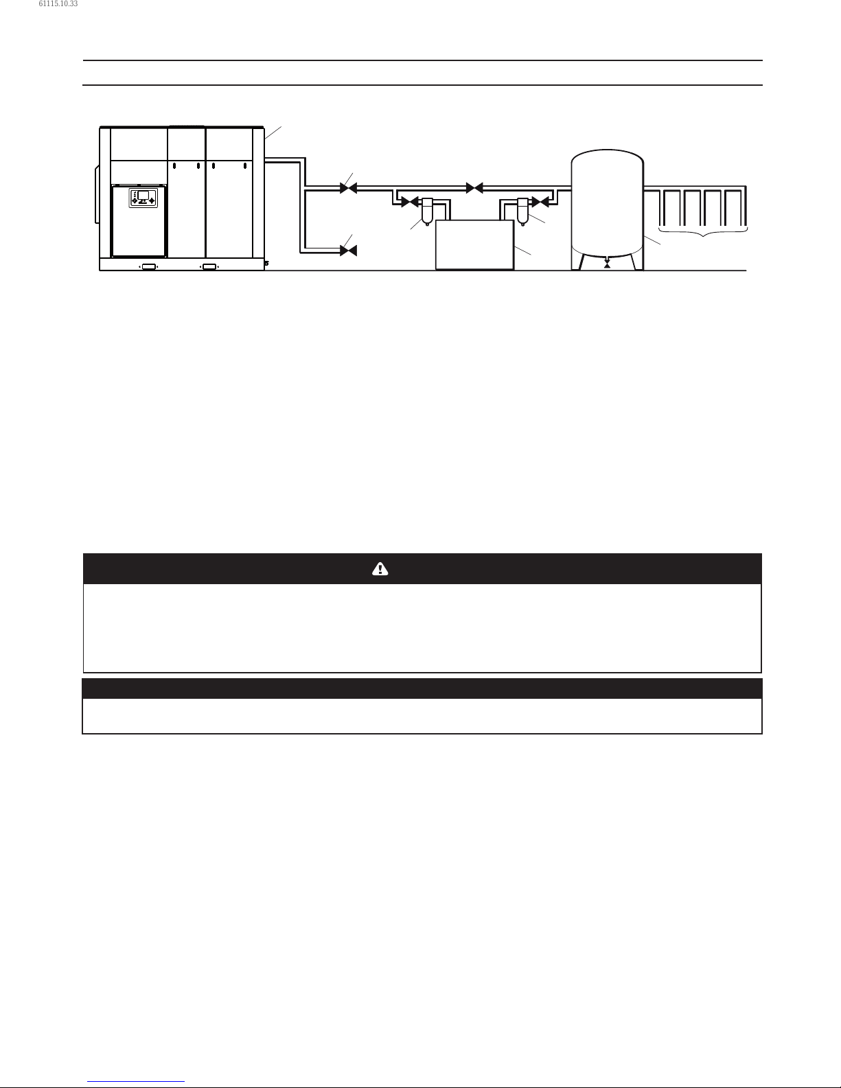
Key
1. Compressor
2. Air Receiver Dry Tank
3. Air Dryer
4. Compressed Air Filters
5. System Demand Points
6. Vent/Drain Trap
7. Isolation Valve
8. Air Receiver (“Wet Tank”)
The compressor can be installed on any level oor
capable of supporting it. A dry, well ventilated area
where the atmosphere is as clean as possible is
recommended.
•
The area selected for the location of the compressor
should be free of dust, chemicals, metal lings, paint
fumes and overspray.
Hard surfaces may reect noise with an apparent
increase in the decibel level. When sound transmission
is important, a sheet of rubber or cork can be installed
beneath the compressor to reduce noise. Flexible piping
may be required.
See the general arrangement drawing for minimum
space requirements for normal operation and
maintenance.
Minimum space in front of the control panel door as
required by national or local codes shall be maintained.
Ambient temperatures higher than 46 °C (115 °F) shall be
avoided, as well as areas of high humidity.
•
•
•
•
•
CAUTION
A minimum of 1 m (3.3ft) all round the compressor is recommended. If headroom is restricted, then the exhaust
should be ducted or deected away from the machine.
Screw type compressors [1] should not be installed in air systems with reciprocating compressors without means of
isolation such as a common receiver tank. It is recommended that both types of compressor be piped to a common
receiver using individual air lines.
NOTICE
If ducting is tted, the sump breather needs to be piped outside the enclosure to avoid back pressure into the
compression module.
1
5
4
2
3
4
6
7
DISCHARGE AND CONDENSATE PIPING
It is essential when installing a new compressor [1], to review
the total air system. This is to ensure a safe and eective
total system. One item which should be considered is liquid
carryover. Installation of air dryers [3] is always good practice
since properly selected and installed they can reduce any
liquid carryover to zero.
To assure long trouble free operation of a compressor
operating with ON-LINE OFF-LINE control, the system volume
must be large enough to keep the load/unload cycles to a
minimum (greater than 2 minutes).
A receiver [2], installed before the feeder lines [5], may be
necessary to ensure that the total system volume is not less
than 2.0 U.S.Gallons per rated delivery C.F.M.
Discharge piping should be at least as large as the discharge
connection of the compressor. All piping and ttings should
•
be suitably rated for the discharge pressure.
It is important to install an isolation valve [7] within 3 feet (1
meter) of the compressor.
It is good practice to install line lters [4].
Include a means [6] to vent the discharge pipework
downstream from the machine’s check valve and upstream of
the rst system isolation valve [7].
When two rotary units are operated in parallel, provide an
isolation vaIve and drain trap for each compressor before the
common receiver.
The built−in intercooler and aftercooler reduce the discharge
air temperature below the dew point (for most ambient
conditions), therefore, considerable water vapor is condensed.
To remove this condensation, each compressor with built−in
aftercooler is furnished with two moisture separator/solenoid
valve combinations. Since these solenoid valves discharge
61115.10.33
Page 11
80448574 Rev A 11
at dierent pressures, it is extremely important that they
are piped separately into an open drain.
A dripleg assembly and isolation valve should be mounted
near the compressor discharge. A drain line should be
connected to the condensate drain in the base.
IMPORTANT: The drain line must slope downward from the
base to work properly. For ease of inspection of the automatic
drain trap operation, the drain piping should include an open
funnel.
CAUTION
The use of plastic bowls on line lters and other plastic air line components without metal guards can be hazardous.
Their safety can be aected by either synthetic oils or the additives used in mineral oils. From a safety standpoint,
metal bowls should be used on any pressurized system.
NOTICE
Do not use the compressor to support the discharge pipe.
PRIOR TO STARTING
If the electric motor/control wiring should become exposed
or saturated with moisture/water deposits, it must be safely
dried o before attempting to make any part or conductor
electrically live.
Ensure all persons concerned are suitably competent with
electrical installations.
Ensure that there is a safe working procedure which has been
issued by supervisory personnel, and that it is understood by
all persons concerned with the operation of the compressor.
Ensure that the safety procedure to be applied is based on the
appropriate national regulations.
Ensure that the safety procedure is followed at all times.
ELECTRICAL CONNECTION
Feeder cables should be sized by a competent electrical
engineer to meet all power requirements.
IMPORTANT
Ensure that the control circuit is connected to the
transformer tapping that matches the supply voltage.
COOLING WATER PIPING
NOTICE
Water piping to and from the compressor package shall
be atleast as large as the package connection size. Do
not undersize the water piping.
Isolation valves with side drains should be installed on both
the inlet and outlet lines. To maintain cooler cleanliness and
reliability, it is important to install a strainer of 2 mm mesh
size on the inlet line. Strainers are available from
Ingersoll Rand.
•
•
•
The air compressor has a normally closed solenoid valve that
is tted to the water outlet side within the package. The valve
is wired into the air compressor control circuit and closes
when the compressor stops.
Carefully inspect the water system before installing the
air compressor package. Ensure that the piping is free of
scale and deposits that may restrict water ow to the air
compressor package. If water cleanliness is poor, ltration
installed on the water inlet pipe line is recommended.
Proper operation of the compressor requires that the cooling
water ow be provided at a maximum supply temperature of
46 °C (115 °F). See the compressor engineering data sheets for
cooling water ow rates.
Water temperature and pressure gauges should be installed
in the water piping for use in any fault nding of the water
system. Water pressure should ideally be between 3 and 5 bar
(43.5 and 72.5 psi) but shall not be above 10 bar (145 psi).
Water cleanliness is also extremely important. Cleaning of
coolers as a result of fouling is a customer responsibility.
Therefore, it is highly recommended that proper water
quality shall meet the requirements listed in WATER QUALITY
RECOMMENDATIONS later in this section.
VENTING THE WATER SYSTEM
At the initial installation, or for startup after draining the
water system, proceed to vent the system as follows:
Locate the water system vent cock on top of the
intercooler.
Open the water valve(s) allowing water to ow to the
package.
Open the vent cock and allow all air to escape from the
system. When water is observed at the vent cock, close it.
The system is now properly vented.
•
1.
2.
3.
INSTALLATION
61115.10.33
Page 12
12 80448574 Rev A
DRAINING THE WATER SYSTEM
Should it become necessary to completely drain the water
system, proceed as follows:
Disconnect the inlet and discharge water lines from the
connections located at the rear of the unit.
Locate the oil cooler by removing the left and centre rear
panels. Remove the two drain plugs located at the end of
the cooler.
Allow the system to completely drain.
WATER QUALITY RECOMMENDATIONS
Water quality is often overlooked when the cooling system
of a water-cooled air compressor is examined. Water quality
determines how eective the heat transfer rate, as well as the
ow rate will remain during the operation life of the unit. It
should be noted that the quality of water used in any cooling
system does not remain constant during the operation of
the system. The water make–up is eected by evaporation,
corrosion, chemical and temperature changes, aeration, scale
and biological formations. Most problems in a cooling system
show up rst in a reduction in the heat transfer rate, then in a
reduced ow rate and nally with damage to the system.
There are many constituents in the water system that must be
balanced to have a good, stable system. The following major
components should be monitored:
SCALE: Scale formation inhibits eective heat transfer, yet it
does help prevent corrosion. Therefore, a thin uniform coating
of calcium carbonate is desired in the inner surfaces. Perhaps
the largest contributor to scale formation is the precipitation
of calcium carbonate out of the water. This is dependent on
temperature and pH. The higher the pH value, the greater the
chance of scale formation. Scale can be controlled with water
treatment.
CORROSION: In contrast to scale formation is the problem of
corrosion. Chlorides cause problems because of their size and
conductivity. Low pH levels promote corrosion, as well as high
levels of dissolved oxygen.
FOULING: Biological and organic substances (slime) can also
cause problems, but in elevated temperature environments
such as cooling processes they are not a major concern.
If they create problems with clogging, commercial shock
treatments are available.
To ensure good operation life and performance of the
compressor cooling system, the recommended acceptable
ranges for dierent water constituents are included below:
Corrosivity (Hardness, pH, Total dissolved solids, Temperature
at inlet and Alkalinity should be analysed monthly, or if stable
for 3 to 4 months, analysed quarterly.
Acceptable concentration:
Langelier Index 0 to 1
•
1.
2.
•
Iron content should be analysed monthly.
Acceptable concentration:
2 mg/l (2 ppm)
Sulphate content should be analysed monthly.
Acceptable concentration:
50 mg/l (50 ppm)
Chloride content should be analysed monthly.
Acceptable concentration:
50 mg/l (50 ppm)
Nitrate content should be analysed monthly.
Acceptable concentration:
2 mg/l (2 ppm)
Silica content should be analysed monthly.
Acceptable concentration:
100 mg/l (100 ppm)
Dissolved Oxygen content should be analysed daily, or if
stable, analysed weekly.
Acceptable concentration:
0 mg/l (0 ppm) (as low as possible)
Oil and Grease content should be analysed monthly.
Acceptable concentration:
5 mg/l (5 ppm)
Ammonia content should be analysed monthly. Acceptable
concentration:
1 mg/l (1 ppm).
ROTATION CHECK
CAUTION
If the compressor is operated in the opposite direction
of rotation, airend damage may result and is not
warrantable.
Locate the rotation decal on each motor.
DRIVE MOTOR
The correct motor rotation is clockwise when viewed from the
rear or non–drive end of the motor.
For the compressor motor rotation check, the running of the
motor must be as short a time as possible.
After depressing the start button, IMMEDIATELY depress
the ”EMERGENCY STOP” BUTTON. Should the motor
rotation be incorrect, put the main isolator in the OFF
position.
Open the starter box door.
Interchange any two line connections (L1, L2 or L3) at the
starter. Close and fasten the starter box door. Recheck for
correct rotation.
•
•
INSTALLATION
61115.10.33
Page 13
80448574 Rev A 13
FAN MOTOR
Observe the compressor cooling fan. The rotation should
be in accordance with the fan rotation decal axed to the
fan motor. Cooling air should exhaust from the top of the
compressor enclosure.
Should the motor rotation not be correct, put the main
isolator in the OFF position.
Interchange any two fan motor leads at the fan manual motor
starter (MMS). Close and fasten the starter box door. Recheck
for correct rotation.
CAUTION
Do not operate the machine with the panels removed
as this may cause overheating and operators to be
exposed to high noise levels.
Do not start or operate the machine in temperatures below
or approaching 0 °C (32 °F), because the operation of the
regulation system, the unloader valve, the safety valve, will be
compromised. Your Ingersoll Rand distributor will advise on
low ambient modications.
• ELECTRICAL DATA
An independent electrical isolator should be installed
adjacent to the compressor.
Feeder cables should be sized by the customer/electrical
contractor to ensure that the circuit is balanced and not
overloaded by other electrical equipment. The length of
wiring from a suitable electrical feed point is critical as voltage
drops may impair the performance of the compressor.
Feeder cable connections to studs L1–L2–L3 on isolator
should be tight and clean.
The applied voltage must be compatible with the motor and
compressor data plate ratings.
The control circuit transformer has dierent voltage tappings.
Ensure that these are set for the specic applied voltage prior
to starting.
CAUTION
Never test the insulation resistance of any part of
the machines electrical circuits, including the motor
without completely disconnecting the Xe controller.
•
INSTALLATION
61115.10.33
Page 14

14 80448574 Rev A
OPERATING INSTRUCTIONS
BASIC OPERATION
NOTICE
The language and compressors of measure displayed on
the controller will be preset before leaving the factory.
If these are required to be changed, contact your local
Ingersoll Rand service provider.
PRIOR TO STARTING
Check that the lubricant level is at least visible in the center
of the sight glass and add lubricant if necessary. Refer to the
maintenance procedures for setting the correct level.
Ensure that the discharge air isolation valve is open. Switch
on the main electrical isolation switch. The control panel will
illuminate, indicating that the line and control voltages are
available.
INITIAL CHECK SEQUENCE
The controller will perform an initial check sequence if the
compressor receives initial power to the controller or has
experienced an trip reset. While the initial check sequence
occurs, the controller will display a “Checking Machine”
message.
During the initial check sequence, the controller will check
the control system for proper operation. During this time,
if any items are found inoperative, a trip will occur and the
compressor will not start.
After completion of the initial check sequence, the controller
will then display “READY TO START’. This process should be
completed within 10 seconds.
START SEQUENCE
The compressor will initially start by the operator pressing the
local start button or receiving a remote start command. The
compressor will start loaded at the end of star delta transition
period for a star delta starter or wait for a period of time equal
to the starter time set point for a remote starter.
STOP SEQUENCE
The compressor can be stopped by a local or remote
stop, a shutdown due to a trip, or an emergency stop.
All of the above conditions will cause the compressor to
stop immediately, except the local or remote stop. A local
or remote stop will open the blowdown valve and the
compressor will run for up to 10 seconds. The compressor
will stop if the system pressure reaches the oine pressure
setpoint. However, if the compressor stops for this reason,
it will automatically restart when the system pressure falls
below the online pressure set point.
NOTICE
If the compressor has to be stopped in an emergency
depress the emergency stop button located underneath
the instrument panel.
•
•
•
•
EMERGENCY STOPPING
If the compressor has to be stopped in an emergency
press the emergency stop button located underneath the
instrument panel.
This will over-ride the normal unload/stop button and will
immediately stop the compressor.
RESTARTING AFTER EMERGENCY STOPPING
If the compressor has been switched o because of a
compressor malfunction, identify and correct the fault before
attempting to restart.
If the compressor has been switched o for reasons of safety,
ensure that the compressor can be operated safely before
restarting.
Refer to the PRIOR TO STARTING and START SEQUENCE
instructions earlier in this section before restarting the
compressor.
•
•
61115.10.33
Page 15
80448574 Rev A 15
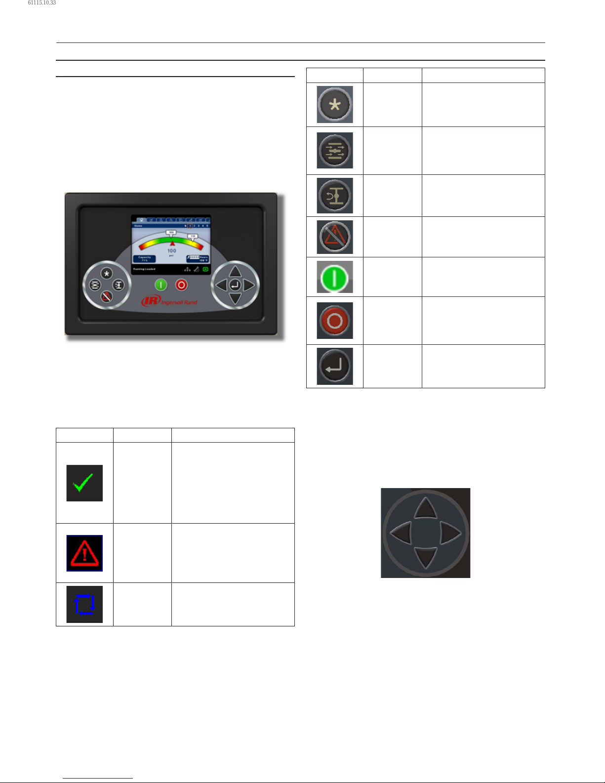
INTERFACE DATA AND KEYS
Xe–90M/145M
The standard user interface conguration of the controller
consists of the membrane and the LCD display. The
membrane consists of ve command keys (Start, Stop, Load,
Unload, and Reset), four navigation keys (Up, Right, Left and
Down), and an Edit mode selection key (Enter). These keys,
in conjunction with the color graphics display and the LED
icons, make up the user interface to the compressor.
Xe–90M/145M
LED STATUS ICONS
Three LED icons are used to indicate the current status of the
control system from a distance and are located on the upper
left side of the user interface.
Icon Name Function
OK
Illuminates when no
Warnings or Trips are sensed.
Can be in a Ready or Not
Ready state.
This icon will ash when
the machine is Running
Unloaded.
Alert
Illuminates when a Warning
(ashes) or Trip (constant on)
is sensed.
Can be in a Ready (Warning)
or Tripped state.
Auto
Illuminates when the
compressor stops in auto
restart.
COMMAND KEYS
These keys command the controller to perform actions as
specied in the following table. When any of these keys are
pressed the action below will be initiated and logged in the
event log.
•
•
•
Key Name Function
--- None
Load
Puts the compressor into the
selected mode of operation.
Unit will load if the pressure
conditions are right.
Unload
Puts the compressor into an
unloaded state. Unit will run
unloaded indenitely.
Reset
Clears Warnings and Trips
once the condition is
corrected.
Start Starts the compressor.
Stop
Stops the compressor. This
button should be pressed
instead of the E-Stop for
normal stopping operation.
Enter
Toggles the display between
the Navigation mode and the
Edit mode.
Xe–90M/145M Command Keys
NAVIGATION KEYS
There are four navigation keys (UP, RIGHT, DOWN and LEFT).
While the ENTER key is not considered a navigation key, it
is used in conjunction with the navigation keys to make or
conrm a selection.
Xe–90M/145M’s Navigation Keys
•
OPERATING INSTRUCTIONS
61115.10.33
Page 16
16 80448574 Rev A
The navigation keys roll over. Pressing one of the navigation
keys will lead the user down a navigation path. Each time
the key is pressed, another step in the path is taken. Once
the end of a navigation path is reached, pressing the key one
more time will bring the user back to the beginning of the
path. Pressing the opposite key will move the user through
the navigation path in the opposite direction. Once the
beginning is reached, pressing the opposite key will take the
user to the end of the path.
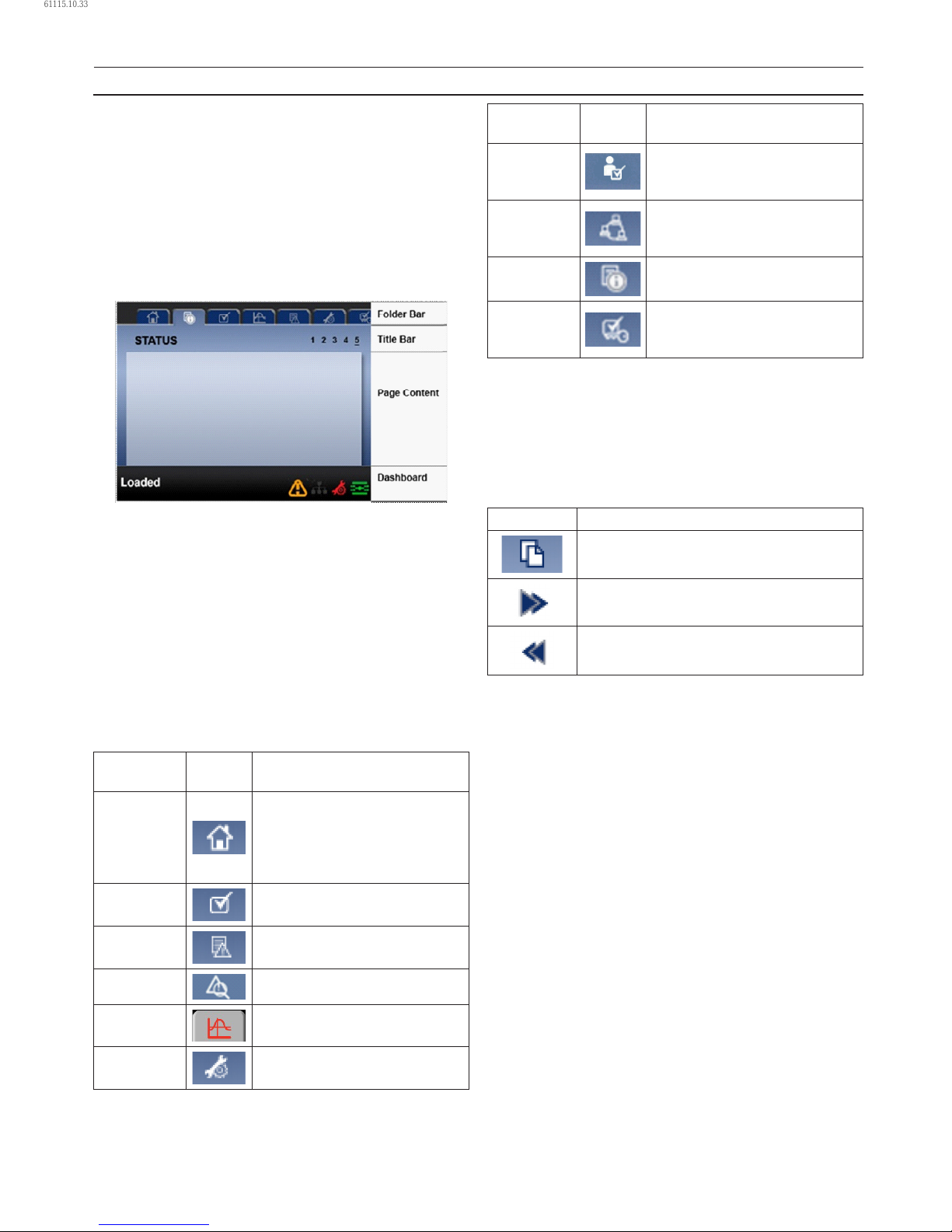
DISPLAY LAYOUT
Xe–90M/145M’s Display Layout
Folder Bar: Uses tabs to graphically identify each
folder.
Title Bar: Identies current folder and page
(underlined).
Page Content: Content of the current page.
Dashboard: Displays system status.
FOLDER NAVIGATION AND ICONS
To move among the tabbed folders shown on the LCD display,
press the RIGHT and LEFT keys. The navigation rolls over from
the last to the rst folder and vice-versa.
Folder
Name
Icon Description
Home
System performance and status
main information. The rst page
of this folder is the default page
when the controller rst powers
up.
Operator
Settings
System options and conguration
settings.
Events System events log.
Trip History Details on the most recent trips.
Graphing
On-board graphing of system
data (Xe–145M Only).
Maintenance
Status and notication setup for
compressor maintenance items.
•
•
Folder
Name
Icon Description
General
Settings
General settings such as
Language, Time, and Units of
Measure.
Integral
Sequencing
Intergral Sequencing
communication status and
conguration.
Status
Measurements or status from/of
all analog and digital I/O.
Factory
Settings
Compressor tuning parameters.
Also displays hardware and
software versions.
Folder Bar Icons
PAGE NAVIGATION
Once the desired folder is selected, press the DOWN key to
move to the page selection area and then use the RIGHT and
LEFT keys to select the desired page. Use the UP key to get
back to the folder tabs.
Icon Description
Start of the page selection area.
Indicates that there are more pages available
by navigating right.
Indicates that there are more pages available
by navigating left.
Title Bar Page Icons
ACCESSING PARAMETERS
After the desired page is selected, the page’s parameters can
be selected by using the DOWN key. The cursor will move to
the next parameter each time the DOWN key is pressed. Use
the UP key to go back to the previous one.
The cursor rolls over, so once the last parameter is selected,
pressing the DOWN key will navigate the cursor to the Folder
Bar. If the rst parameter is selected, pressing the UP key will
move the cursor to the page selection area.
Once selected, access parameters by pressing the ENTER key.
Make changes using the NAVIGATION keys and then enter the
setting by pressing the ENTER key again. After a parameter
is accessed, pressing the ENTER key will enter the current
setting into the control program and navigate the cursor back
to the selected parameter on the page.
When the cursor is on a parameter that has an enabled/
disabled box, pressing the ENTER key will cause the setting to
toggle.
•
•
OPERATING INSTRUCTIONS
61115.10.33
Page 17
80448574 Rev A 17
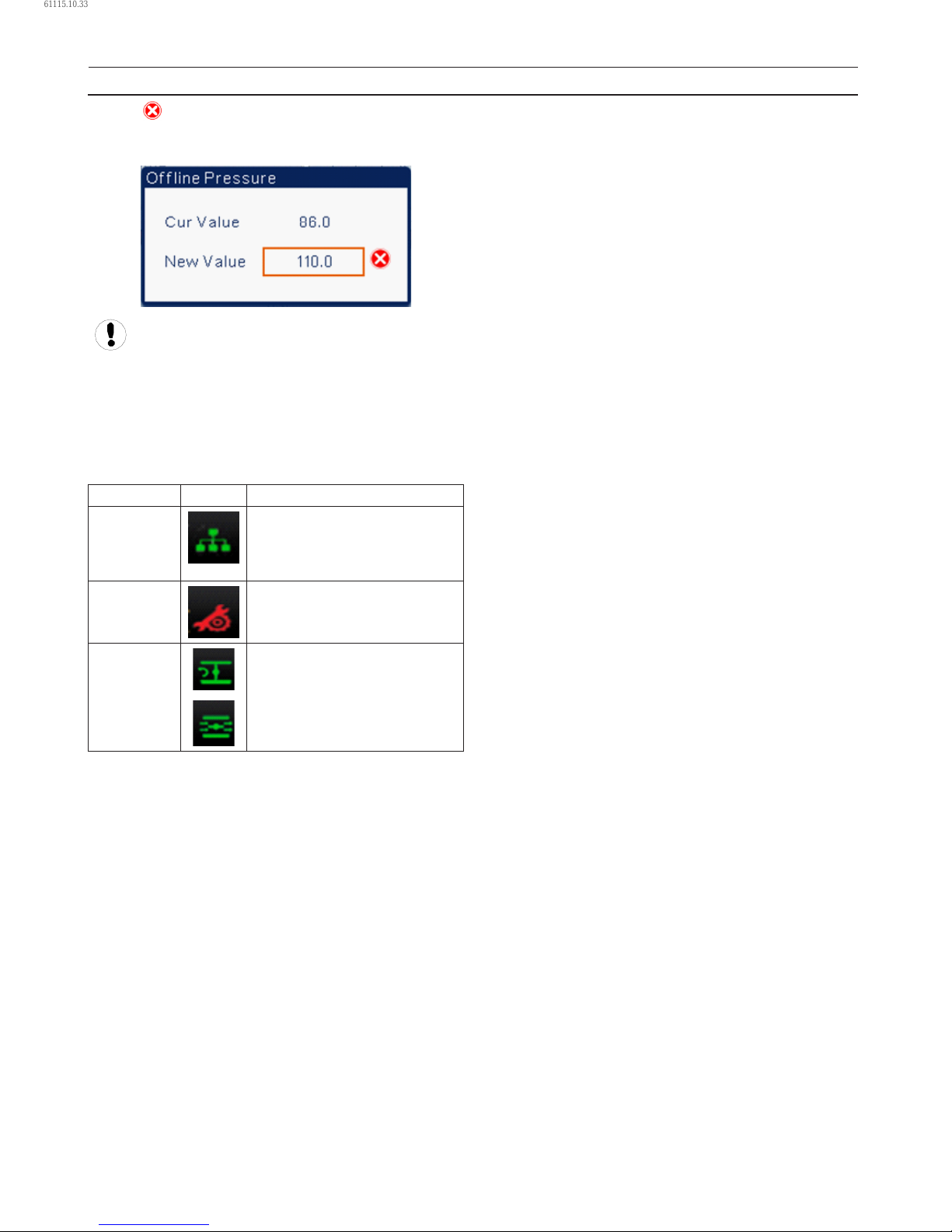
The icon appears on numeric entry windows (see gure
below). Placing the cursor on it and then pressing the ENTER
key will cancel the entry and any changes that were made.
Not all pages have adjustable parameters. Some just
have read-only information.
DASHBOARD ICONS
The dashboard is intended to be a quick at-a-glance view of
system status. The following table lists standard dashboard
icons and their denition. Note that the color of these icons
changes based on the state set by the application while
running.
Name Icon Description
Remote
Control
Remote control is enabled. This
can be Remote Start/Stop, COM
Control, Integral Sequencing or
Web Control.
Service
Required
A service reminder is nearing or
has expired (i.e.: an air or oil lter
needs to be changed).
Unloaded
or
Loaded
Compressor is in the unloaded
state.
Compressor is in the loaded state.
Xe–90M/145M’s Dashboard Icons
DASHBOARD STATUS MESSAGES
The dashboard also displays the current operating state of the
compressor. The following states can be encountered during
machine operation:
Ready to Start – The compressor currently has no trip
or start inhibit conditions present. The machine can be
started by pressing the start button at any time.
•
•
•
Starting – A start command has been given to the
compressor and the start sequence is being performed.
The time period for this state can vary depending on the
starter type of the machine.
Load Delay – The compressor is waiting for a small
period of time after starting before allowing the machine
to load. This ensures the machine is at operating
conditions before loading
Running Loaded – The compressor is operating and
producing air. The inlet valve is open and the blowo
valve is closed.
Running Unloaded – The compressor is operating,
but not producing air. The inlet valve is closed and the
blowo valve is open.
Auto-Restart – The compressor has stopped due to
pressure rising above the oine or auto-stop setpoints
and auto-restart being enabled. The compressor will
automatically restart when pressure falls to the online or
target pressure setpoint.
Stopping – The compressor has received a stop
command and the stop sequence is being performed.
Blowdown – The compressor must wait for a brief period
of time after stopping its motor before it is allowed to
start again.
Not Ready – The compressor has detected a condition
that will not allow the compressor to start. The condition
must be cleared before a start is allowed, but does not
need to be acknowledged.
Tripped – The compressor has detected an abnormal
operational condition that has stopped the machine. A
trip must be acknowledged by hitting the reset button
before the compressor can start.
Processor Init – The controller is being initialized.
•
•
•
•
•
•
•
•
•
•
OPERATING INSTRUCTIONS
61115.10.33
Page 18
18 80448574 Rev A
SIERRA COMPRESSOR
HOME FOLDER
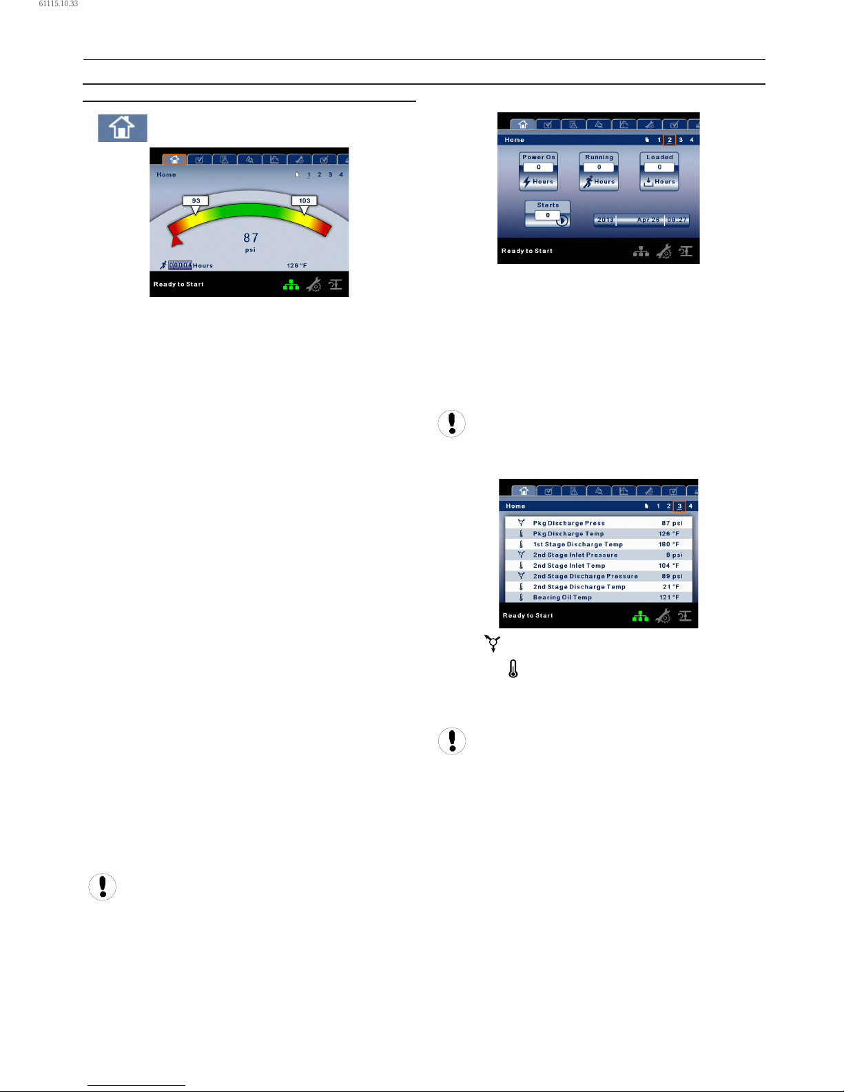
PAGE 1 – SYSTEM OVERVIEW
This is the factory default display after powering up the
system.
Load Pressure – indicated in the white box and by the
white arrow, which is always left of center on the gauge. The
compressor will load when package discharge pressure falls
below this value.
Unload Pressure – indicated in the white box and by the
white arrow, which is always right of center on the gauge. The
compressor will unload when package discharge pressure
rises above this value.
Package Discharge Pressure – indicated by the large
numbers centred below the gauge and by the red arrow. This
is the air pressure that the compressor is supplying to the
plant.
Pressure Unit of Measure – indicated below the Package
Discharge Pressure. This is selectable from the GENERAL
SETTINGS folder.
Package Discharge Temperature – indicated by the
numbers in the lower right of the display. This is the
temperature of the compressed air/at the discharge of the
compression module. The Package Discharge Temperature is
only displayed if the Hot Discharge option is disabled.
Second Stage Discharge Temperature – indicated by
the numbers in the lower right of the display. This is the
temperature of the compressed air at the discharge of the
2nd stage compression module.
Temperature Unit of Measure – indicated to the right of the
Airend Discharge Temperature. This is selectable from the
GENERAL SETTINGS folder.
Run Hours – indicate the number of hours the compressor
has been running.
All information on this page is read only.
•
•
PAGE 2 – COUNTERS
Hour Meters – Indicates the hours that: the controller has
been powered up, the compressor has been running, and the
compressor has running loaded.
Starts – Indicates the number of times a start is attempted on
the compressor.
Date and Time – Indicates the current date and time. This is
adjustable and congurable in the GENERAL SETTINGS folder.
All information on this page is read only.
PAGES 3 THRU 4 – ANALOG INPUTS
Pressure is indicated by this icon.
Temperature is indicated by this icon.
Any sensor that is not installed or is reporting a failure will
show an X symbol.
All information on these pages is read only.
The following analog inputs are displayed in this section:
Package Discharge Pressure – The pressure the compressor
is delivering to the plant.
Package Discharge Temperature – The temperature of the
air after passing through the After-cooler.
1st Stage Discharge Temperature – The temperature of
the air at the discharge of the 1st stage of the compression
module.
•
•
OPERATING INSTRUCTIONS
61115.10.33
Page 19
80448574 Rev A 19
2nd Stage Inlet Pressure – The pressure of the air at the
intake of the 2nd stage of the compression module.
2nd Stage Inlet Temperature – The temperature of the air at
the intake of the 2nd stage of the compression module.
2nd Stage Discharge Pressure – The pressure of the air at
the discharge of the 2nd stage of the compression module.
2nd Stage Discharge Temperature – The temperature of
the air at the discharge of the 2nd stage of the compression
module.
Bearing Oil Temperature – The temperature of the coolant
oil at the bearings of the compression module shaft.
Bearing Oil Pressure – The pressure of the coolant oil at the
bearings of the compression module shaft.
Inlet Vacuum – Vacuum reading at the inlet valve.
Remote Pressure (optional) – An optional pressure sensor
that reads pressure at a point outside of the compressor
package. Usually this would be on a common tank.
Oil Filter Pressure Drop – Dierential pressure across the
lter. Higher values indicate an older or clogged lter.
OPERATOR SETTINGS FOLDER
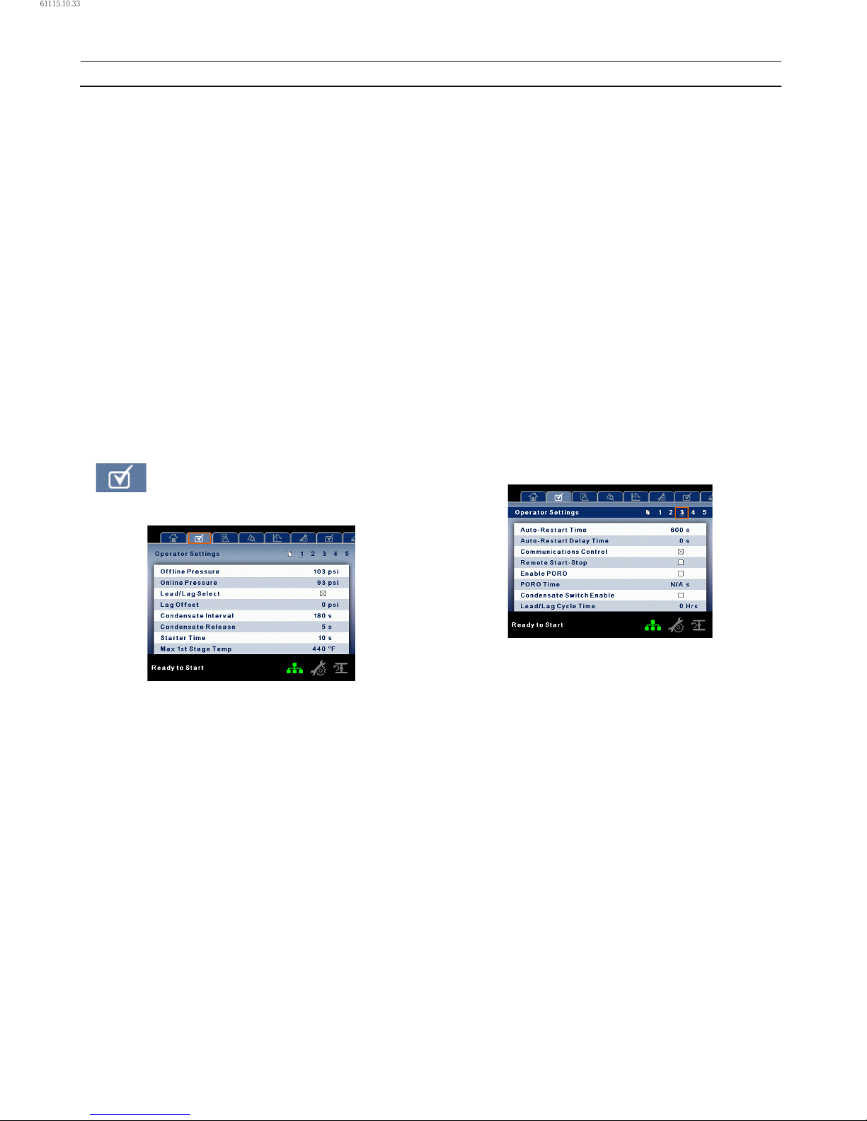
PAGE 1–2 OPERATOR SETTINGS
The below values are all setpoints:
Oine Pressure – The compressor will unload when package
discharge pressure rises above this value.
Range (in PSI): 75 to Rated Pressure +3.
Online Pressure – The compressor will load when the
package discharge pressure falls below this value.
Range (in PSI): 65 to Oine Pressure -10.
Lead/Lag – When this box is checked the compressor is
operating as a lead machine. Unchecking the box causes the
machine to run as a lag machine.
Lag Oset – If the machine is running as a lag compressor,
the lag oset will be subtracted from the online and oine
setpoints.
Range (in PSI): 0–45, depending on the online and oine
setpoints. The Lag Oset will never allow you to exceed
the minimum or maximum values of the online and oine
setpoints.
•
•
Condensate Release Time – Time period that determines
how long the condensate drain valve will remain open every
cycle.
Range: 2–20 seconds.
Condensate Interval Time – Time period that determines
how long the condensate drain will remain closed every cycle.
Range: 90–270 seconds.
Starter Time – Time period that the compressor needs in
order to come up to operating speed after a start command
before being able to produce air.
Range (in seconds): 5–30.
Max 1st Stage Temperature – Setting that determines at
what temperature the compressor will trip if the 1st Stage
Discharge Temperature exceeds it.
Range (in °F): 300–440.
Max 2nd Stage Temperature – Setting that determines at
what temperature the compressor will trip if the 2nd Stage
Discharge Temperature exceeds it.
Range (in °F): 328–428.
The parameters on these pages are adjustable any time.
PAGES 3–5 OPERATOR OPTIONS
The below values are all setpoints:
Auto-Restart Time – The time period the compressor must
run unloaded before stopping in auto-restart. This time
period begins the moment that package discharge pressure
rises above the oine setpoint. Both this time period and
the minimum motor run timer (10 minutes) must be satised
before the compressor will stop in auto restart.
Range (in seconds): 120–900.
Auto-Restart Delay – The time period after the package
discharge pressure has fallen below the online setpoint
before the compressor can automatically restart.
Range (in seconds): 0–60.
COM Control – Enabling this setpoint allows the compressor
to be controlled by a serial or Ethernet device, such as an X8I.
This is equivalent to the “Sequencer” option on older Intellisys
controllers.
Remote Start/Stop – Enabling this setpoint allows the
compressor to be started and stopped using the digital inputs
on the controller.
Enable PORO – Enabling this setpoint will allow the
•
OPERATING INSTRUCTIONS
61115.10.33
Page 20
20 80448574 Rev A
compressor to automatically restart after a power outage has
been restored if the compressor was running loaded at the
time of the outage. PORO is an option and the option module
must be purchased and installed before this feature can be
turned on.
PORO Time – Time after the controller power has been
restored and controller has nished booting before the
compressor will perform a PORO start. During this time the
PORO Horn will sound.
Range (in seconds): 10–600.
Condensate Level Installed – Setpoint to enable the level
switch used to detect a blocked condensate drain.
Lead/Lag Cycle Length – The time period that controls how
long the compressor will remain in the lead position before
switching to lag. Setting this to 0 will disable this function.
Range: 0–750 hours.
Scheduled Start Day – Day (or days) of the week for which a
scheduled start will be performed. The compressor will start
when its onboard clock matches the day, hour, and minute
of the scheduled start setpoints. Scheduled Start/Stop is
an option and the option module must be purchased and
installed before this feature can be turned on.
Scheduled Start Hour – Hour of the day for which a
scheduled start will be performed. Scheduled Start/Stop is
an option and the option module must be purchased and
installed before this feature can be turned on.
Scheduled Start Minute – Minute of the hour for which a
scheduled start will be performed. Scheduled Start/Stop is
an option and the option module must be purchased and
installed before this feature can be turned on.
Scheduled Stop Day – Day (or days) of the week for which a
scheduled stop will be performed. The compressor will stop
when its onboard clock matches the day, hour, and minute
of the scheduled stop setpoints. Scheduled Start/Stop is
an option and the option module must be purchased and
installed before this feature can be turned on.
Scheduled Stop Hour – Hour of the day for which a
scheduled stop will be performed. Scheduled Start/Stop is
an option and the option module must be purchased and
installed before this feature can be turned on.
Scheduled Stop Minute – Minute of the hour for which a
scheduled stop will be performed. Scheduled Start/Stop is
an option and the option module must be purchased and
installed before this feature can be turned on.
Enable High Dust Filter – Enabling this when a high dust
lter is installed will adjust the change inlet lter warning and
high inlet vacuum trip thresholds to a higher value.
Enable Remote Pressure Sensor – Enabling this allows the
compressor to load and unload based o a sensor reading
installed in a remote location.
Please note that in order to disable Scheduled Start/Stop,
the Scheduled Start and Stop days, hours, and minutes must
match exactly.
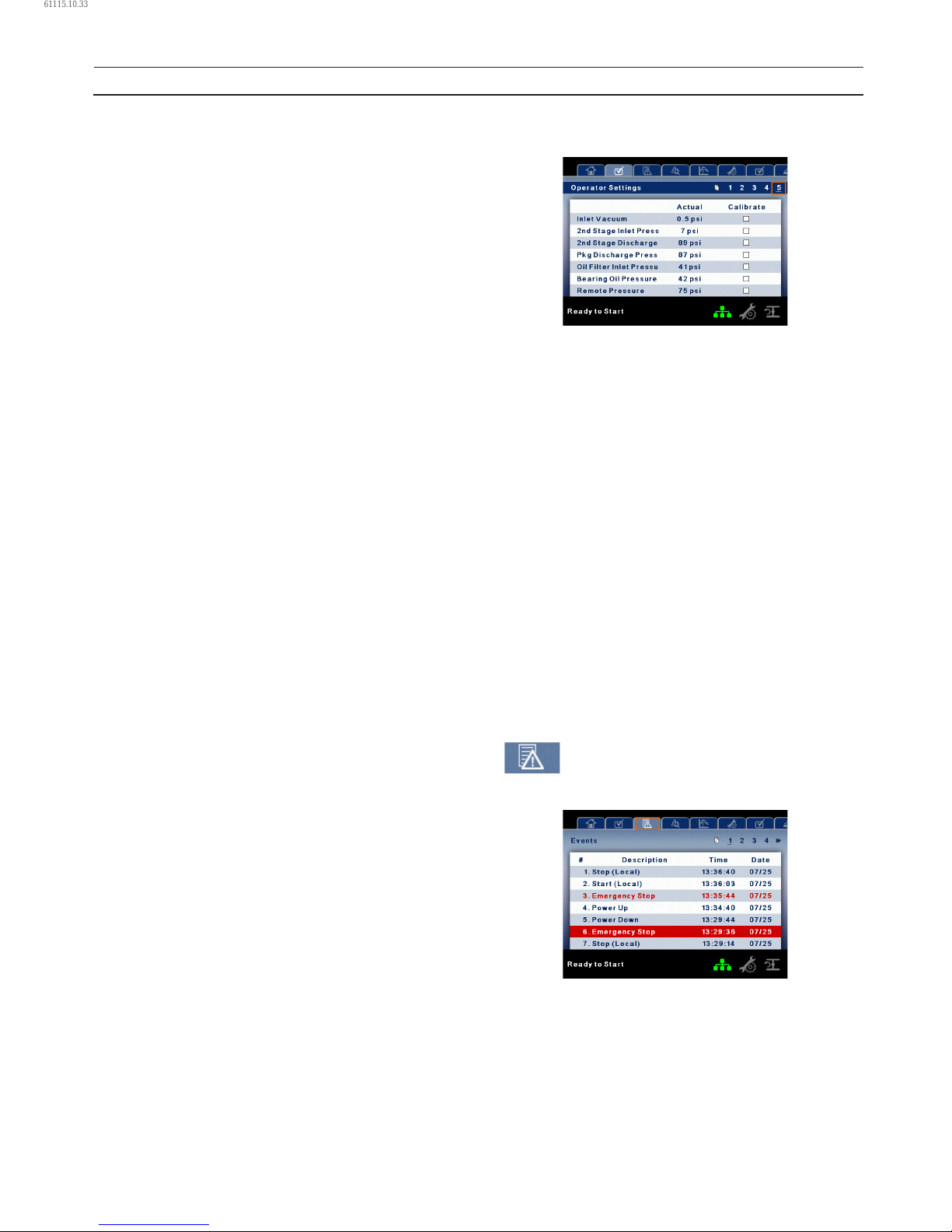
PAGES 6 CALIBRATE SENSORS
Sensor calibration can only take place when the machine is
stopped and there is no pressure on the sensor. Calibration
only needs to take place after a sensor is replaced, the
controller is replaced, the controller software is upgraded, or
the operator suspects the sensor reading is in error. Calibrate
a sensor by selecting the checkbox beside the sensor name.
Each of the sensors listed below can be calibrated:
Inlet Vacuum (1AVPT)
2nd Stage Inlet Pressure (2APT)
2nd Stage Discharge Pressure (3APT)
Package Discharge Pressure (4APT)
Oil Filter Inlet Pressure (5OPT)
Bearing Oil Pressure (6OPT)
Remote Pressure (10APT) – Only on units with the
remote sensor option.
Please note that if a sensor is currently reading a value that is
+/-10% of its range from zero, the sensor will not be able to
be calibrated and an warning will be logged in the event log.
Please make sure the sensor is being exposed to atmosphere
before attempting calibration.
EVENTS FOLDER
PAGES 1 TO A MAX OF 50
The pages in the Events folder document up to the last 250
events that the controller has experienced, with the time and
date of the occurrence. The events are recorded in sequence,
with number one being the newest and 250 being the oldest.
When a new event occurs, it becomes number one and all
others are shifted up in number.
The page numbers in the Title Bar are used to scroll through
•
•
•
•
•
•
•
•
•
•
OPERATING INSTRUCTIONS
61115.10.33
Page 21

80448574 Rev A 21
the events, with each page displaying up to seven. Page
one displays events one through ve, page two displays six
through ten, and so on.
The following items will generate an event:
Power On
Power O
Press the Start Key
Press the Stop Key
Press the Load Key
Press the Unload Key
Starting the compressor remotely
Stopping the compressor remotely
Warning
Trip
Start Inhibit.
Active Warnings will be highlighted in amber while
acknowledged Warnings will have amber text.
Active Trips will be highlighted in red while acknowledged
Trips will have red text.
Active Start Inhibits will be listed in the Event log, but not
highlighted. The display will indicate the compressor is not
ready to start if a start inhibit is active.
WARNING EVENTS LIST
Change Inlet Filter
On-Screen Text: Change Inlet Filter
Will occur if 1AVPT is greater than 0.7 psi vacuum for units
rated in horsepower, or 1 psi for units rated in kilowatts
(1.3 psi vacuum for all units if the high dust lter option is
enabled) the unit has been loaded for at least 8 seconds and
the inlet valve is on the open limit switch. This condition must
exist for 3 seconds before the warning is issued.
Change Oil Filter
On-Screen Text: Change Oil Filter
This warning will occur if the compressor is running and the
Bearing Oil Temperature sensor reads a value greater than
120 °F, and the Oil Filter Pressure Drop is greater than 13 psi
for 3 seconds or longer.
Sensor Failure
On-Screen Text: 5OPT Failure, 7ATT Failure
This will occur whenever sensors 5OPT, 7ATT, or 10APT
are recognized as missing or broken. The sensor failure
message shall follow the following format: 5OPT FAILURE.
This condition must exist for 3 seconds before the warning is
issued.
Auxiliary 1
On-Screen Text: Auxiliary 1
This will occur if auxiliary input 1 closes. The contact must be
closed for at least 3 seconds before the warning will occur.
•
•
•
•
•
•
•
•
•
•
•
•
•
•
•
•
Auxiliary 2
On-Screen Text: Auxiliary 2
This will occur if auxiliary input 2 closes. The contact must be
closed for at least 3 seconds before the warning will occur.
SERVICE
Service warnings occur when the unit has operated a certain
number of hours, based on the total hours. Service warnings
can have multiple levels, depending on the service level
selection. A service level selection of 0 disables service
warnings.
Service Level 1
On-Screen Text: SVC Required
If service level 1 has been selected for the unit, a “SERVICE
REQUIRED” warning will be issued on hour intervals equal to
the service time period set point. This warning can be reset
the same as any other warning.
Service Level 2
On-Screen Text: 100 hours to Svc, SVC Required, Service Alarm
If service level 2 has been selected for the unit, the service
complete factory set point will be used to clear a level 2
service warning and reset the service time or date. The service
complete can be reset before a service warning occurs.
The initial “SERVICE REQUIRED” warning will occur at total
hour intervals equal to the service time period set point.
However, 100 hours before this a “100 HOURS TO SERVICE”
warning will occur. This warning can be reset the same as
any other warning. One hundred hours later the “SERVICE
REQUIRED” warning will occur. This warning can be reset
the same as any other warning, however this warning will
return in 24 hours if the service complete factory set point
has not be set. If the service complete has not been set, 100
hours later, the “ALARM – SERVICE REQUIRED” warning will
be issued. This warning can only be cleared by the service
complete factory set point. Once the service complete factory
set point is set, indicating the service is completed, the time
for the next “SERVICE REQUIRED” warning will be calculated
by adding the service time period to the total hours value,
with the “100 HOURS TO SERVICE” warning occurring 100
hours before and the “ALARM – SERVICE REQUIRED” warning
occurring 100 hours after that time.
High Discharge Pressure
On-Screen Text: High Disch Pres
Will occur if the unit is using a remote sensor or is under the
control of an external device, such as an X8I, is loaded, and
the discharge pressure (4APT) is greater than the maximum
oine pressure. This condition must exist for 3 seconds before
the warning is issued. If this condition occurs, the compressor
will automatically unload. The unit will be available to reload
once the discharge pressure falls to the rated pressure value.
Load or Stop Unit – Will occur if the controller remains in a
force unloaded state (by pressing the unload key) for a period
of 10 minutes.
•
•
•
•
•
OPERATING INSTRUCTIONS
61115.10.33
Page 22

22 80448574 Rev A
Invalid Calibration
On-Screen Text: Invalid Cal
Will occur if the sensor zero value is +/-10% of its scale. See
Sensor Calibration.
Check SD Card
On-Screen Text: Check SD Card
The controller has detected a problem with the SD card
during the last boot cycle and is using les from internal
memory. The controller will function normally, but web page
access may not work properly.
TRIP EVENTS LIST
High Intercooler Condensate
On Screen Text: High I/C Condensate
Will occur if the Condensate Level Switch option is installed
and enabled, and the condensate level switch is closed
for a time period of 60 seconds or greater. A closed switch
indicates that the drains are not working properly.
High Intercooler Pressure
On Screen Text: High I/C Pressure
Will occur if the compressor is running loaded, the 2nd Stage
Inlet Pressure sensor reads a value greater than 43 psi, and the
1st Stage Discharge Temperature sensor reads a value greater
than 410 °F (430 °F for rated pressures above 125 psi). This will
also occur if the compressor is running, started less than
7 seconds ago, and the 2nd Stage Inlet Pressure sensor reads
a value greater than 10 psi.
High 2nd Stage Pressure
On Screen Text: High 2nd Stg Press
Will occur if the compressor is running and the 2nd stage
discharge pressure sensor reads a value greater than 15 psi
above the rated pressure setpoint.
High Line Air Pressure
On Screen Text: High Line Air Press
Will occur if the compressor is running and the package
discharge pressure sensor reads a value that is greater than
15 psi above the rated pressure setpoint.
Low Bearing Oil Pressure
On Screen Text: Low Bearing Oil Press
Will occur if the compressor leaves the starting state and the
Bearing Oil Pressure sensor reads a value that is less than 15
psi. This will also occur if after leaving the starting state, the
Bearing Oil Pressure does not rise above 34 psi within
8 seconds. Lastly, this will occur if the compressor is running
unloaded, has been running for at least 7 seconds, and the
Bearing Oil Pressure sensor reads a value of less than 34 psi
for 3 seconds or longer.
•
•
•
•
•
•
•
•
2nd Stage Over Ratio
On Screen Text: 2nd Stage Over Ratio
Will occur if the compressor is running and the equation (2nd
Stage Discharge Pressure +14.5 psi) / (2nd Stage Inlet Pressure
+14.5 psi) is a value greater than 5 for 2 seconds or longer.
High 1st Stage Temperature
On Screen Text: High 1st Stage Temp
Will occur if the compressor is running and the 1st stage
discharge temperature sensor reads a value greater than the
High 1st Stage Temperature setpoint.
High 2nd Stage Temperature
On Screen Text: High 2nd Stage Temp
Will occur if the compressor is running and the 2nd stage
discharge temperature sensor reads a value greater than the
High 2nd Stage Temperature setpoint.
High Intercooler Air Temperature
On Screen Text: High I/C Temp
Will occur if the compressor has been started for at least
15 seconds, is running, and the 2nd stage inlet temperature
sensor reads a value greater than 140 °F.
High Bearing Oil Temperature
On Screen Text: High Bearing Oil T
Will occur if the compressor has been started for at least
15 seconds, is running, and the bearing oil temperature
sensor reads a value greater than 170 °F.
Starter Fault 1SL (2SL)
On-Screen Text: Starter Fault 1SL, Starter Fault 2SL
Will occur if the unit tries to start and either of the starter
auxiliary contacts are already closed.
Main Motor Overload
On-Screen Text: Main Motor OL
This will occur if the motor overload relay opens. The contact
must be open for at least 3 seconds before the trip will occur.
Fan Motor Overload
On-Screen Text: Fan Motor OL
Will occur if a fan motor overload relay contact opens. The
contact must be open for at least 3 seconds before the trip
will occur.
Remote Stop Failure
On-Screen Text: Rem Stop Fail
Will occur if the remote start/stop option is enabled, the
remote stop button remains open and either start button is
pressed.
•
•
•
•
•
•
•
•
•
OPERATING INSTRUCTIONS
61115.10.33
Page 23
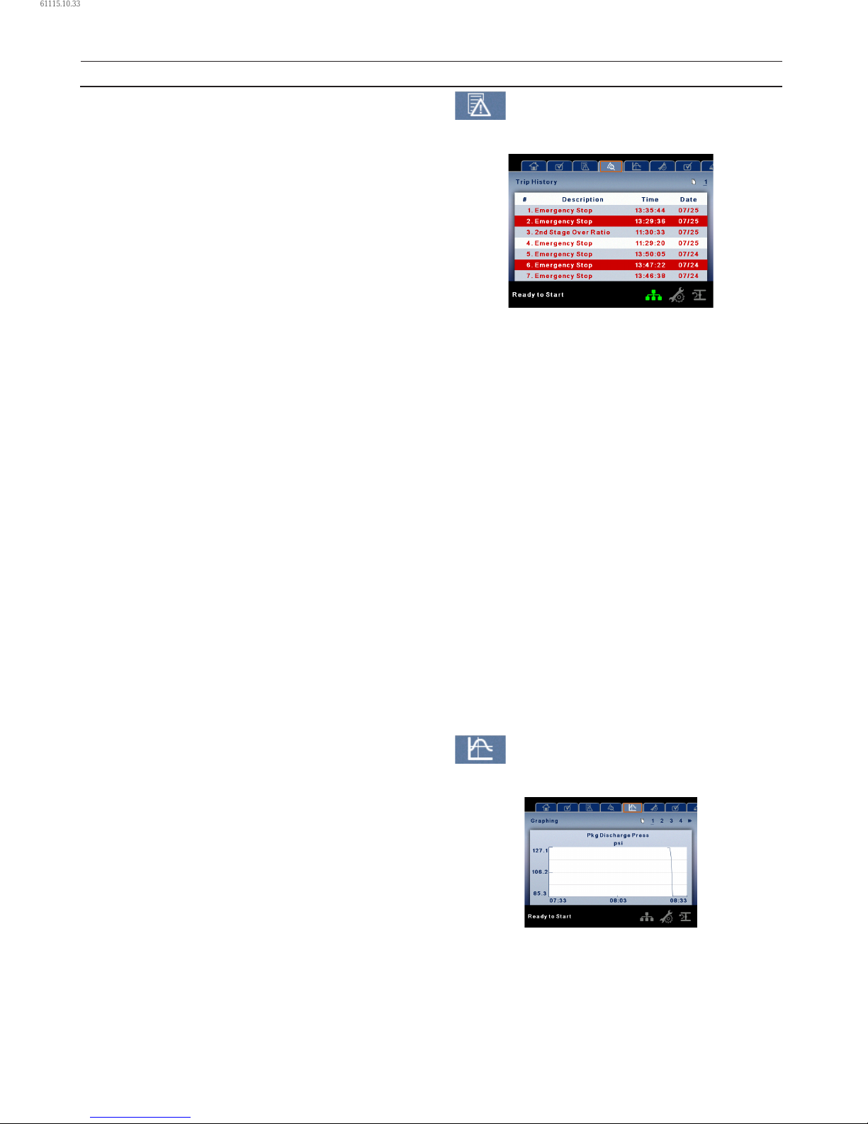
80448574 Rev A 23
Remote Start Failure
On-Screen Text: Rem Start Fail
Will occur if the remote start/stop option is enabled, the unit
is started by the remote start button, and the button stays
closed for 7 seconds after the unit starts.
Sensor Failure
On-Screen Text: 1AVPT Failure, 2APT Failure, 3APT Failure,
4APT Failure, 60PT Failure, 2ATT Failure, 3ATT Failure 4ATT
Failure, 5OTT Failure.
This will occur when a sensor is recognized as missing or
broken. The sensors aected by this trip are 1AVPT, 2APT,
3APT, 4APT, 2ATT, 3ATT, and 5OTT. The sensor should be
displayed along with the sensor failure message. The sensor
failure message shall follow the following format: 1AVPT
Failure.
Emergency Stop
On-Screen Text: Emergency Stop
This will occur when the EMERGENCY STOP button is
engaged.
Inlet Restriction
On-Screen Text: Inlet Restriction
This will occur if the unit has running loaded for at least
8 seconds and the inlet vacuum is greater than 3 psi. This
warning will also occur if the unit is running unloaded and the
inlet vacuum is greater than 13.3 psi.
Excessive Unloaded Run
On Screen Text: Excessive Unload
Will occur if the compressor remains in the forced unload
condition (by pressing the unload key) for a time period of
20 minutes.
Start Inhibit List
High 1st Stage Temperature
On Screen Text: High 1st Stage Temp
Will occur if the 1st stage discharge temperature sensor reads
a value greater than 95% of the high 1st stage discharge
temperature setpoint.
High 2nd Stage Temperature
On Screen Text: High 2nd Stage Temp
Will occur if the 2nd stage discharge temperature sensor
reads a value greater than 95% of the high 2nd stage
discharge temperature setpoint.
High Bearing Oil Temperature
On Screen Text: High Bearing Oil T
Will occur if the bearing oil temperature sensor reads a value
greater than 161 °F.
•
•
•
•
•
•
TRIP HISTORY
PAGES 1 TO A MAX OF 3
The pages in the Trips History folder document up to the last
15 trips that the controller has experienced, and time stamps
each. The trips are recorded in sequence, with number one
being the newest and 15 being the oldest. When a new trip
occurs, it becomes number one and all others are shifted up
in number.
The page numbers in the Title Bar are used to scroll through
the events, with each page displaying up to seven. Page
one displays events one through ve, page two displays six
through ten, and so on.
The following items will generate an entry in the trip history.
Trips.
Active Trips will be highlighted in red while cleared Trips will
have red text.
The trip history also records compressor data at the time
of the trip to assist in diagnostics and troubleshooting.
Navigating to the trip entry and hitting the enter button will
bring up the trip history dialog box.
While the dialog box is active, press the left and right keys in
order to scroll through the displayed data. The name of the
trip will always be shown in the title bar of the dialog box.
Press enter when nished viewing the data to return to the
trip history screen.
GRAPHING FOLDER
PAGES 1 THRU 5 – INDIVIDUAL GRAPHS
Variable (Read Only) Each page graphs one variable,
displaying the variable name and unit of measure in the top
center of the page. The variables that will be graphed on each
of the ve pages are selectable from page six. The units of
measure are selectable from the GENERAL SETTINGS folder.
Y–Axis (Read Only) – is auto-scaling.
•
•
•
•
•
OPERATING INSTRUCTIONS
61115.10.33
Page 24
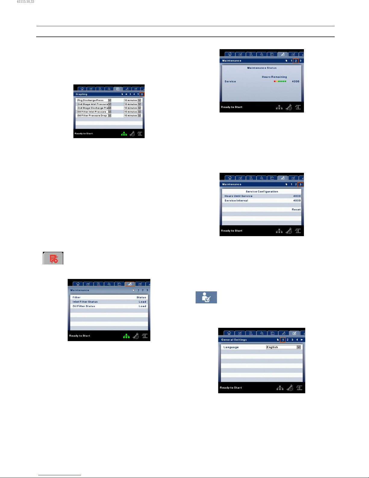
24 80448574 Rev A
X–Axis (Read Only) – The time duration is selectable from
page six. The sample rate varies, based on the selected
duration.
The graph plots a minimum of 255 readings.
PAGE 6 – GRAPHING SELECTIONS
The selections for page one through ve are organized
sequentially in rows. The top row has page one selections and
the bottom row has page ve selections.
Variables – include all analog inputs as well as some
calculated variables. The amount of variables will vary
depending on the compressor type and the options it has.
Duration – selectable from the following ve times:
10 minutes
30 minutes
60 minutes
12 hours
24 hours
These times are xed and cannot be changed.
MAINTENANCE FOLDER
PAGE 1 – FILTER STATUS
This page displays the status of the lters. The lter status will
either be “OK” or “Change” depending on the compressor’s
diagnostic readings. If a lter reaches the “change’ status, a
warning will be issued and the service indicator will light up
yellow to notify the user. Please note that the compressor
must be in a “Running Loaded” state to check these
maintenance items. If the compressor is not in a running state
– the status will display “Load,” unless a maintenance indicator
has been issued when the machine was running and has not
yet been reset.
The following lters are displayed:
Oil Filter
Inlet Filter.
•
•
•
•
•
•
•
•
•
•
PAGE 2 – MAINTENANCE STATUS
This page displays the time until the unit should be serviced.
The service meter will deplete as the hours count down closer
to a service appointment. Once the counter reaches the
yellow zone, the service indicator will light up yellow. Once
the counter reaches the red zone the service indicator will
light up red and maintenance must be performed.
PAGE 3 – MAINTENANCE CONFIGURATION
This page allows the user to set the service interval and to
reset the counter after the service has been performed.
The service interval may be set to any value between 1000
and 8000 hours, but must be set in accordance with the
factory maintenance schedule. After maintenance has been
performed, the user can reset the counter by navigating to
the Reset button and pressing the enter key.
GENERAL SETTINGS FOLDER
All parameters in the general settings folder are adjustable.
PAGE 1 – LANGUAGE SELECTION
Language (< >) is selectable from the following 30 selections:
English (default) Finish Latvian Slovak
Bulgarian French Lithuanian Slovenian
Chinese, simplied German Maltese Spanish
Croatian Greek Norwegian Swedish
•
•
•
•
OPERATING INSTRUCTIONS
61115.10.33
Page 25
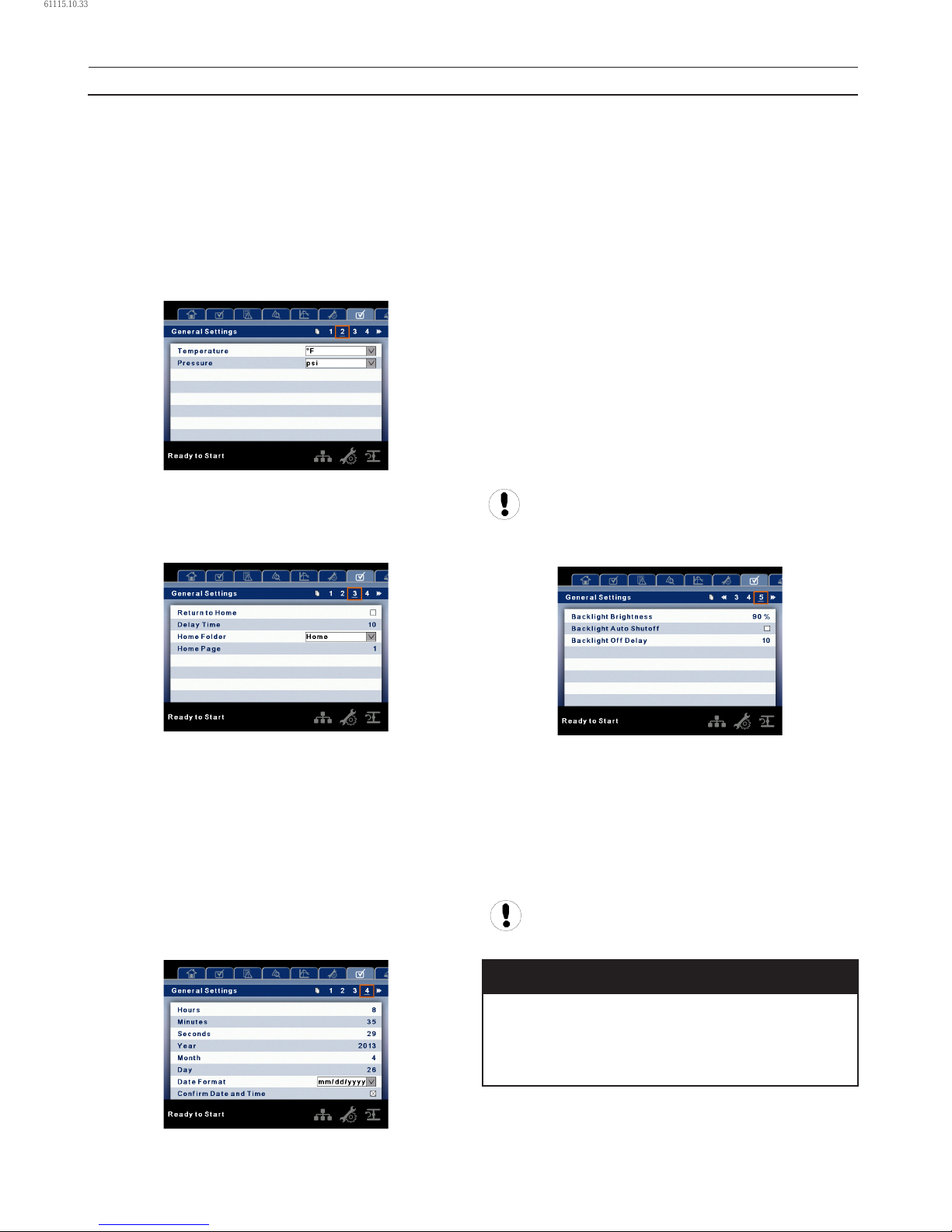
80448574 Rev A 25
Czech Hungarian Polish Thai
Danish Italian Portuguese Turkish
Dutch Indonesian Romanian
Estonian Korean Russian
The controller will display all screens in the selected language
and only one language can be selected at a time.
Each language appears in its native translation.
PAGE 2 – UNITS OF MEASURE SETTINGS
Temperature is selectable between °F and °C.
Pressure is selectable between psi, kpa, bar, kg/cm2.
PAGE 3 – HOME PAGE SELECTION
Auto Return to Home enables the controller to return the
display back to the selected Home Page if there is no user
activity for the Delay Time shown. This is only enabled when
an “x” appears in the checkbox.
Delay Time determines how many seconds of inactivity it will
take before the controller will return to the Home Page.
Select Home Folder is used to select the Home Folder.
Select Home Page is used to select the Home Page within
the selected Home Folder.
PAGE 4 – TIME AND DATE SETTINGS
•
•
•
All items are adjustable.
Hours allows the current hour to be set. The hours format is
xed on 24 hour.
Minutes allows current minutes to be set.
Seconds allows current seconds to be set.
Year allows current year to be set.
Month allows current month to be set.
Day allows current day to be set.
Date Format is selectable between dd/mm/yyyy (default)
and mm/dd/yyyy.
Conrm New Time and Date is used to verify that changes
to selections are desired. An “x” must appear in the checkbox
before any changes will take aect.
The controller will continue to display any changes, even
when the selections have not been conrmed and the user
exits the page, then returns. Cycling of the power returns all
selections to their current settings.
The controller does not support Daylight Savings
Time.
PAGE 5 – BACKLIGHT SETTINGS
Backlight Brightness – adjusts the brightness of the display.
Enable Backlight Auto-O – enables the controller to shut-
o the backlight if there is no user activity for the delay time
shown.
Backlight Auto-O Delay Time – determines how many
seconds of inactivity it will take before the controller will shuto the backlight.
.
The backlight will be switched on whenever any of
the controller’s keys are pressed.
NOTICE
The start, stop, load, unload, reset, and acknowledge
keys on the xe–90m/145m remain functional while the
backlight is switched o. It is recommended to press
the enter key or one of the navigation keys in order to
switch the backlight on.
•
OPERATING INSTRUCTIONS
61115.10.33
Page 26
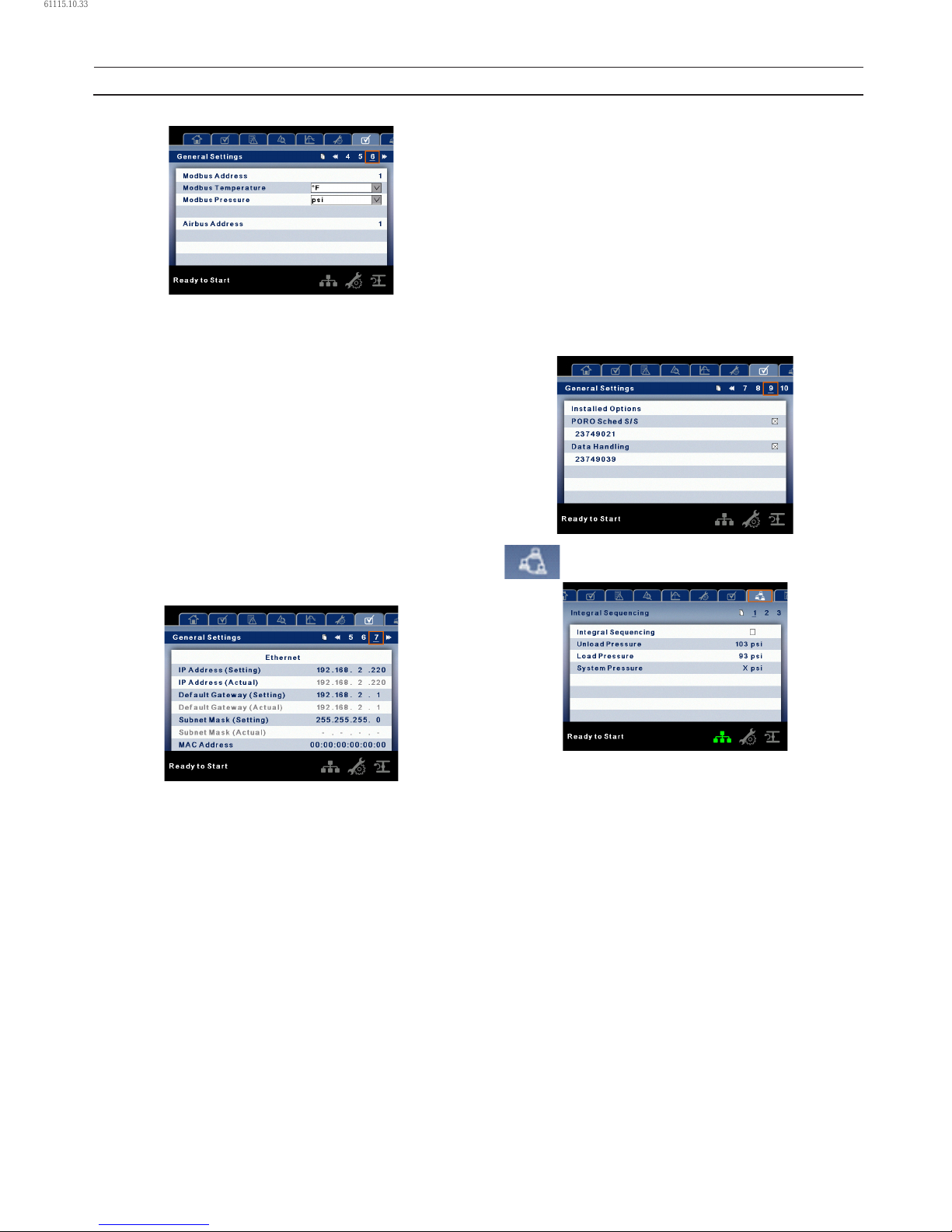
26 80448574 Rev A
PAGE 6 – SERIAL PORT ADDRESS SETTINGS
This page allows the user to set up the network addresses
for the RS–485 networks the controller is capable of
communicating with.
MODBUS Address – Sets the modbus node ID for the
controller to communicate with a Modbus capable device,
this can be any value between 1 and 247.
MODBUS Pressure – Sets the unit type for pressure data read
out via the Modbus connection.
MODBUS Temperature – Sets the unit type for temperature
read out via the Modbus connection.
Airbus Address – Sets the airbus address that allows the
controller to communicate over Integral Sequencing or an
X–Series system controller network.
PAGES 7 AND 8 – ETHERNET SETTINGS
IP Address Setting – When DHCP is not enabled, this
setpoint sets the IP address of the controller.
IP Address Actual – This will match the IP address setting
when DHCP is not enabled. If DHCP is enabled this will display
the address assigned to the controller by the DHCP server.
Default Gateway Setting – Setpoint for the default gateway.
Default Gateway Actual – Current reading/setting for the
default gateway.
Subnet Mask Setting – Setpoint for the subnet mask.
Subnet Mask Actual – Current reading/setting for the subnet
mask.
MAC Address – This is the unique hardware MAC address for
the controller. This can not be changed.
Enable DHCP – Allow the controller to automatically receive
an IP address from the Local Area Network (LAN).
•
•
Apply – After editing the desired setpoint navigate to the
accept setting and press enter in order for the values in the
setting variables to be conrmed by the controller.
Cancel – Discard any changes made to the Ethernet settings.
PAGES 9 AND 10 OPTION MODULE INFORMATION
The option module information screen allows the user to see
which software options have been installed in the controller.
An option module that is installed will show up with an “X”
in the appropriate box. The option part number is displayed
with the option name.
If no options are installed, this screen will not appear on the
controller.
INTEGRAL SEQUENCING FOLDER
Integral Sequencing allows the compressor to be networked
with up to three other compressors (xed or variable
speed) to maintain a stable system pressure by loading and
unloading compressors as needed. Integral sequencing
requires no additional hardware other than a serial two wire
connection daisy chained between all compressors in the
system.
Please note that the compressor’s address in the integral
sequencing system is dened by the airbus address that is
set on the general settings folder. Also note that the pressure
signal used to determine when to load or unload another
compressor is based on the pressure reading from the
compressor at address 1 in the system.
Integral Sequencing – Enabling Integral Sequencing selects
this compressor to be the leader of the integral sequencing
system. It is important that only one compressor in the
sequence be selected as the lead compressor.
Unload Pressure – Determines the pressure at which a
compressor will be unloaded by the system.
•
•
OPERATING INSTRUCTIONS
61115.10.33
Page 27
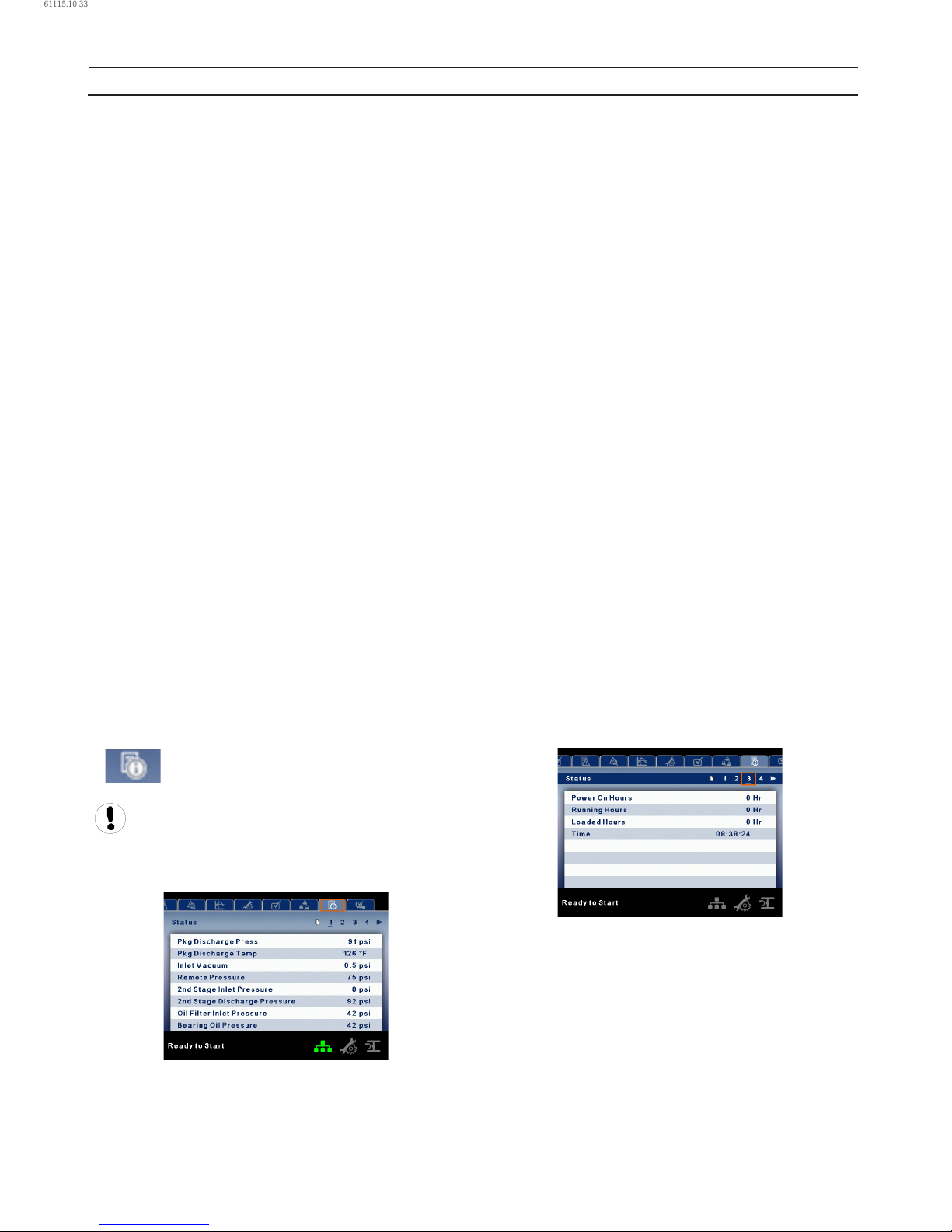
80448574 Rev A 27
Load Pressure – Determines the pressure at which a
compressor will be loaded by the system.
System Pressure – Shows the current pressure reading that
the system is using for control. This is typically compressor 1’s
package discharge pressure reading.
Start Delay Interval – Determines the amount of time
between loading compressors. This prevents all compressors
from loading at once.
Damping – The pressure control “Damping” setting which is
used to tune how quickly the system responds to pressure
deviations. The default is 10 and should not normally be
changed.
Tolerance – The pressure control “Tolerance” setting, which is
used to tell the system how to respond to changes in pressure
above and below the load/unload pressures. The default is 3.0
psi and should not normally be changed.
Number of Compressors – Denes how many compressors
are in the system. There is a maximum of 4.
Sequence – Displays the current load/unload order of the
system. Each compressor in the system is assigned a letter,
with “A” being the compressor to load rst and unload last,
and “D” being the compressor to load last and unload rst.
Priority – Each compressor can be assigned a priority
level. Compressors will only rotate positions with other
compressors of the same priority level.
Rotate Now – Selecting this setpoint will cause the sequence
to shift according to the priorities, regardless of the rotation
interval setpoint.
Rotation Interval – Determines the time period between
sequence rotations.
Time Left – Counts down the time until the sequence
rotation will occur.
STATUS FOLDER
All information on these pages is read only.
Some values may only be visible when the factory
settings password is entered.
PAGES 1 AND 2 – ANALOG INPUTS
Analog Inputs:
The following analog inputs are displayed in this section:
•
•
Package Discharge Pressure – The pressure the
compressor is delivering to the plant.
Package Discharge Temperature – The temperature of
the air after passing through the compressor discharge.
1st Stage Discharge Temperature – The temperature
of the air at the discharge of the 1st stage of the
compression module.
2nd Stage Inlet Pressure – The pressure of the air at the
intake of the 2nd stage of the compression module.
2nd Stage Inlet Temperature – The temperature of the
air at the intake of the 2nd stage of the compression
module.
2nd Stage Discharge Pressure – The pressure of the air
at the discharge of the 2nd stage of the compression
module.
2nd Stage Discharge Temperature – The temperature
of the air at the discharge of the 2nd stage of the
compression module.
Oil Filter Inlet Pressure – The pressure of the coolant oil at
the inlet of the oil lter.
Bearing Oil Pressure – The pressure of the coolant oil at
the bearings of the compression module shaft.
Bearing Oil Temperature – The temperature of the
coolant oil at the bearings of the compression module
shaft.
Inlet Vacuum – Vacuum reading at the inlet valve.
Remote Pressure (optional) – An optional pressure sensor
that reads pressure at a point outside of the compressor
package. Usually this would be on a common tank.
Condensate Level Switch – Shows the status of the
condensate level switch in analog to digital converter
counts.
PAGE 3 – COMPRESSOR DATA
Compressor Data:
Power On Hours – The number of hours the controller
has been powered up.
Running Hours – The number of hours the compressor’s
motor has been running.
Loaded Hours – The number of hours the compressor has
been producing air.
Real Time Clock – Current time of day.
•
•
•
•
•
•
•
•
•
•
•
•
•
•
•
•
•
•
OPERATING INSTRUCTIONS
61115.10.33
Page 28
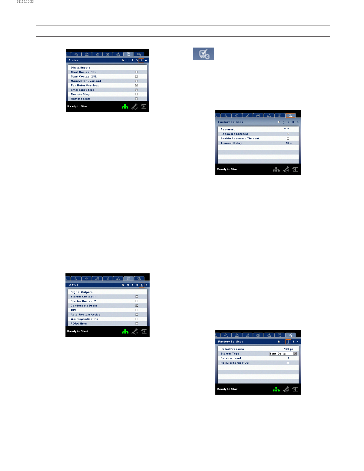
28 80448574 Rev A
PAGES 4 THRU 5 – DIGITAL INPUTS
Digital Inputs:
An “x” in the checkbox beside a digital input indicates that
the input is in its TRUE state. For example, Starter Feedback is
TRUE when its input is in the high state, where as, Emergency
Stop is TRUE when its input is at 0 Vdc.
A password is required to view these pages.
Starter Contact 1SL
Starter Contact 2SL
Main Motor Overload
Fan Motor Overload
Emergency Stop
Remote Stop
Remote Start
Remote Lead/Lag
Remote Load Enable
Remote Load/Unload
Auxiliary Input 1
Auxiliary Input 2.
PAGES 6 AND 7 – DIGITAL OUTPUTS
Digital Outputs:
An “x” in the checkbox beside a digital output indicates that it
is energized. A password is required to view these pages.
Starter Contact 1M
Starter Contact 1S
Condensate Solenoid
Load Solenoids
Stopped in Auto-Restart
Warning Output
PORO Horn
Trip Indication
•
•
•
•
•
•
•
•
•
•
•
•
•
•
•
•
•
•
•
•
•
•
Warning Indication.
FACTORY SETTINGS FOLDER
This folder is for Ingersoll Rand factory and service
personnel. A password must be entered on page one in
order to adjust values in this folder. This folder is used for
setting parameters that are specic to that compressor and
displaying software information for the controller.
PAGE 1 – PASSWORD
Password:
Provides access to enter a valid password to gain access to
password protected parameters. The password is entered by
scrolling down to the password value and pressing the return
key.
Password entered:
This checkbox will indicate a valid password has been
entered. If this checkbox is blank, a valid password has not
been entered or it has timed out. This is read only.
Password timeout enable:
Checking this box will enable the password time feature.
Password timeout:
This timeout along with the password timeout enable allows
the user to set an adjustable amount of time to require a valid
password to be re-entered. Once this timeout is reached reentry of a valid password is required. The timeout counter is
reset after any button press.
PAGES 2 THRU 3 – FACTORY SETTINGS
These pages are used for setting parameters that are
specic to the compressor. All of the factory settings that are
adjustable are listed below. All settings on these pages are
password protected.
Rated Pressure – This is the nominal pressure that the
•
•
•
•
OPERATING INSTRUCTIONS
61115.10.33
Page 29
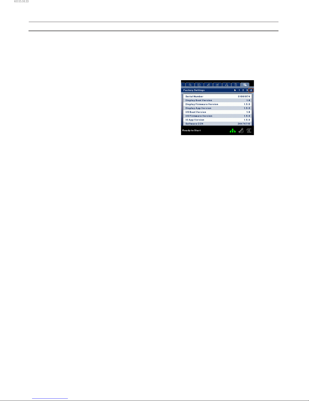
80448574 Rev A 29
compressor can provide. This setpoint is adjustable from
100–150 psi (6.9–10.3 bar) and defaults to 100 psi.
Starter Type (Star-delta, Remote Starter, Soft Starter)
– Choose the starter type installed in the compressor. If this is
not set correctly, the compressor may not start.
Service Level (0, 1, or 2) – Set the service level reminders for
the compressor.
Service Level 0 – Disables all service reminders.
Service Level 1 – A service warning will be issued when
the service time period has been expired. This warning
can be reset by any user.
Service Level 2 – A service warning will be issued
100 hours prior to the service time period expiring.
This 100 hour warning can be reset by any user. At
the expiration of the service time interval the service
warning will again occur. This warning can be reset by
any user but will recur every 24 hours until the service
complete factory setpoint has been set (Password
Required).
Hot Discharge – Enable this setpoint to activate the Hot
Discharge option, which disables the package discharge
temperature sensor.
•
•
•
Power On Hours (Read Only).
Running Hours (adjustable) – Used to adjust the running
hours counter on the compressor.
Loaded Hours (adjustable) – Used to adjust the loaded
hours on the compressor.
PAGES 4 – FACTORY SETTINGS
These pages are used for displaying software information for
the controller. All items are read only.
•
OPERATING INSTRUCTIONS
61115.10.33
Page 30
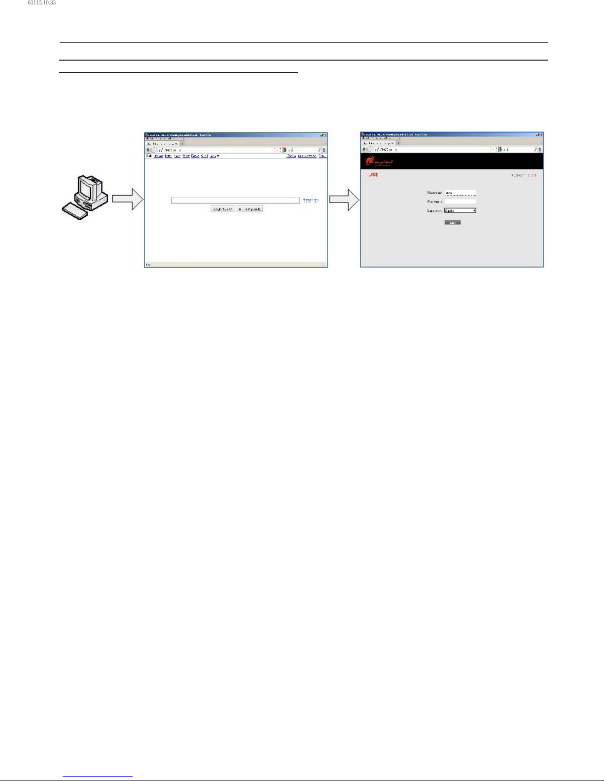
30 80448574 Rev A
WEB ACCESS
Ingersoll Rand Xe–90M/145M web pages are a visualization
application which oers a window using a web browser
on your PC. The web pages allows the user to monitor air
system at a glance or take a more detailed look into system
operation, equipment status and setup through an intuitive
web-page based user interface. To access this application
running on the controller, simply connect via a Web Browser
from any PC using an Ethernet connection. The PC can be
local stand alone or part of a LAN.
The system administrator can assign a user one of three levels of access (view only, user, and administrator) which will
determine which functions will be available to that user. For example, only users with administrator access will be able to make
new accounts and to view or modify the conguration overview parameters. See section Account Management.
The Xe–90M/145M functions as a web server for the compressor. The web server oers the following through the interface:
Display of current operating state of the compressor
Compressor Information – model number, serial number, rated capacity and other details
Start, Stop, Reset Alarm, Load and Unload buttons
Adjust operating parameters
Display of analog signals
Display of hour meters
Display of Event log
Graphing (Xe–145M Only)
Display of maintenance timers
Edit and display of maintenance log
Notication of alarm/trip events via email.
COMMISSIONING PROCEDURES
There are certain parameters that must be congured in order for the controller to properly communicate to the LAN and to
the network. Outlined below is a list of steps that must be completed before the visualization software can be fully utilized.
Please be sure that you have ADMIN rights before attempting to congure the controller.
If you will only be connecting to the controller to a single PC, go to step 1. If you will be using a static IP or DHCP assigned IP
address on your company’s LAN please go to step 2.
Connect the controller to a PC – Follow the procedure outlined in section “CONNECTING TO A PC”. Please go to step 3.
Congure the controller Ethernet settings – Obtain a static IP address from your IT department or have an assigned
domain name for DHCP access. Follow the procedures in “ETHERNET CONFIGURATION”.
Login to the web pages – Follow the procedure in section “LOGIN PROCESS”.
Congure compressor information – Follow the procedures in section “COMPRESSOR INFORMATION”. Make sure you have
the compressor nameplate data available.
Set up user accounts – Follow the procedures in section “ACCOUNT MANAGEMENT”.
•
•
•
•
•
•
•
•
•
•
•
•
1.
2.
3.
4.
5.
OPERATING INSTRUCTIONS
61115.10.33
Page 31
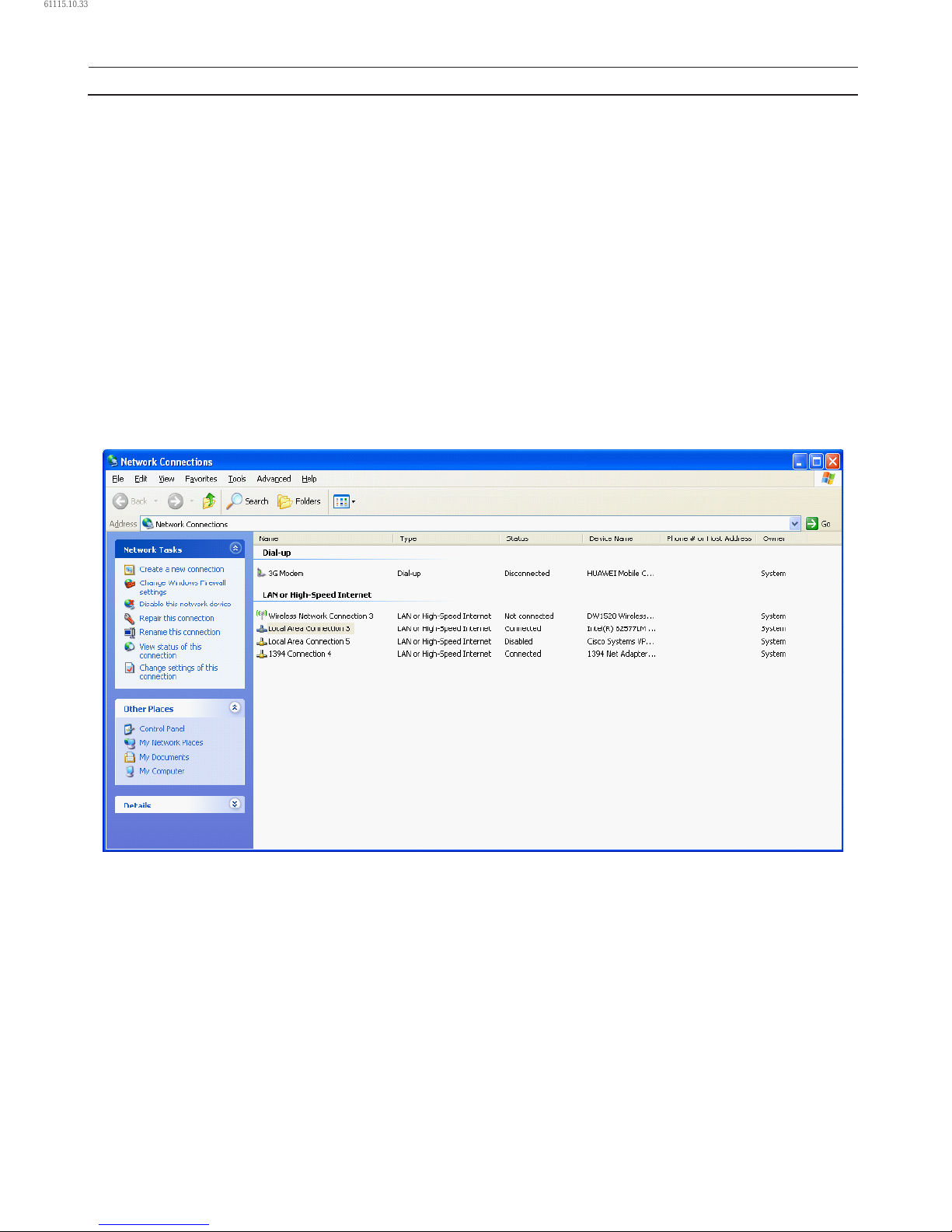
80448574 Rev A 31
CONNECTING TO A PC
In order to congure your computer to communicate point-to-point with the Xe–90M/145M controller, you must rst set the IP
address range of your computer to the default IP address range of the controller. To do this, please follow the instructions listed
below to congure the computer IP address. These settings are accessible using Windows XP by selecting:
Using Classic View:
Select Start
Select Settings
Select Network Connections.
Using XP Start View:
Select Start
Select Control Panel
Select Network Connections.
Please note that the controller ships with a default IP address of 192.168.2.220.
Select “Local Area Connection” from the list.
•
1.
OPERATING INSTRUCTIONS
61115.10.33
Page 32
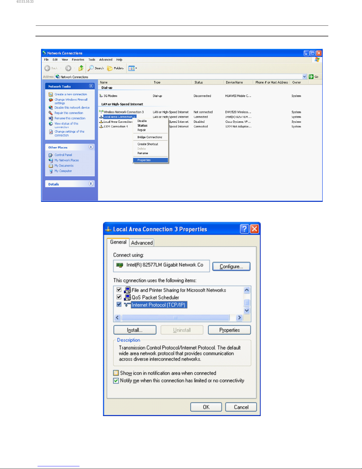
32 80448574 Rev A
2. Right click on the “Local Area Connection” and select “Properties”.
3. Scroll down the connection list to nd the “Internet Protocol (TCP/IP)”. Select the “Internet Protocol (TCP/IP)” and click on
“Properties”.
OPERATING INSTRUCTIONS
61115.10.33
Page 33
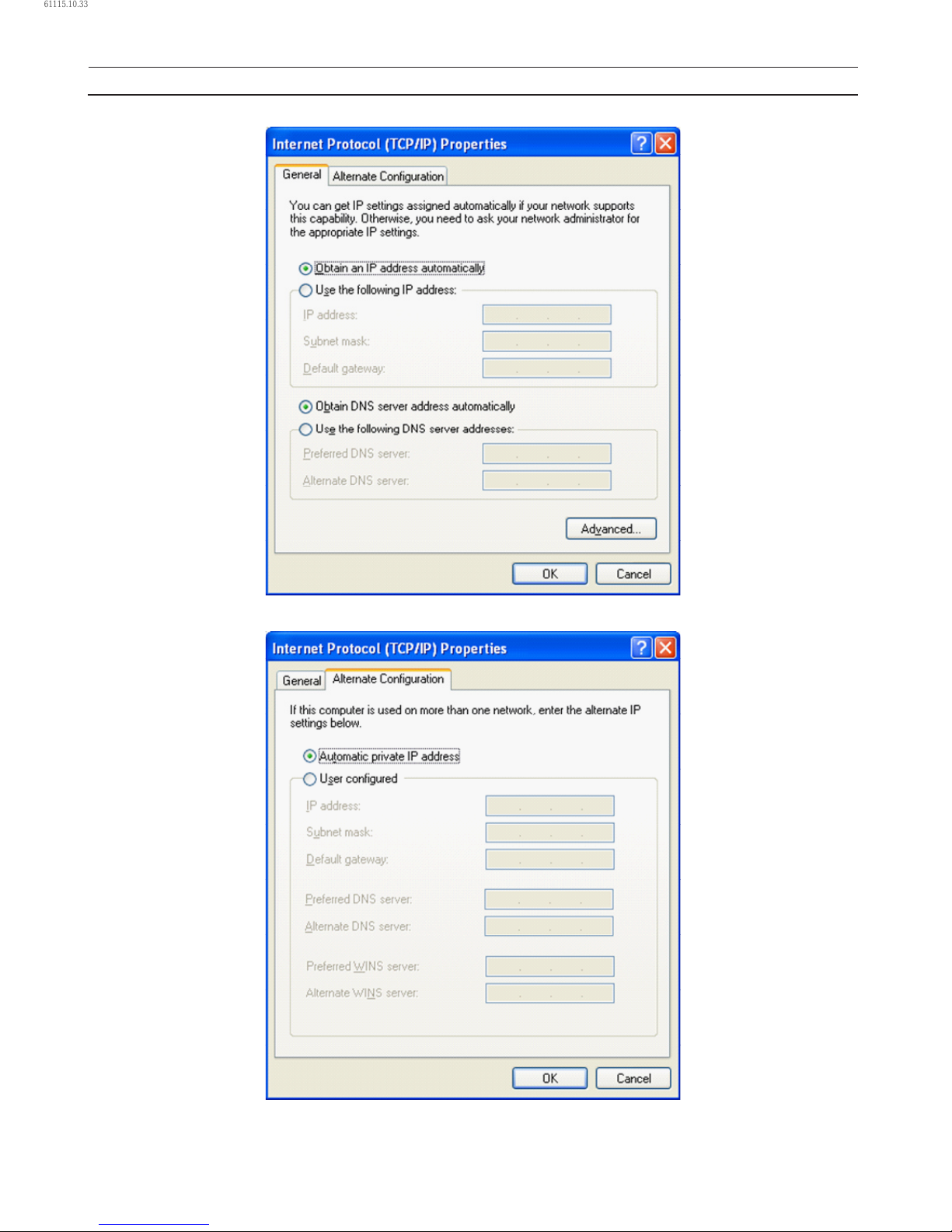
80448574 Rev A 33
4. Click on the “Alternative Conguration” tab.
5. Click on “User Congured” Button.
OPERATING INSTRUCTIONS
61115.10.33
Page 34
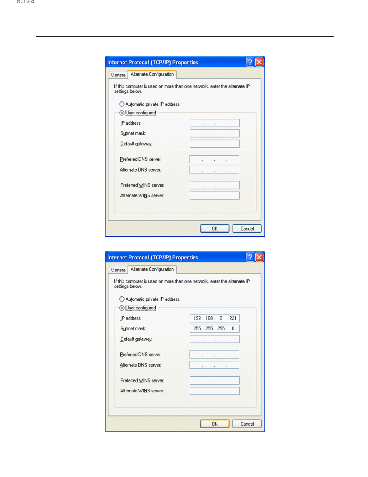
34 80448574 Rev A
6. Enter IP address for the computer (192.168.2.221), Enter the Subnet mask for the computer (255.255.255.0) and leave all
other eld boxes blank.
7. Click on “OK” button when it is complete.
OPERATING INSTRUCTIONS
61115.10.33
Page 35
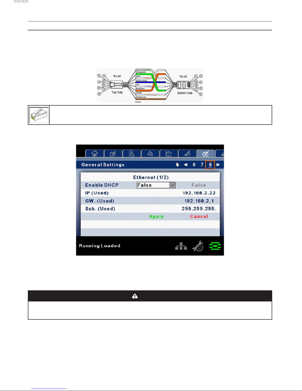
80448574 Rev A 35
8. Connect an Ethernet cable to your computer and to the controller. Within a minute, the computer will make a connection
to the controller. Once connected, you will be able to log into and congure the controller.
ETHERNET WIRES
Wiring the network is accomplished by connecting the user computer to the controller using Category 5 (or better) cables. The
connection point on the user computer is a RJ–45 port located on the Network Interface card.
The Ethernet cables are terminated with CAT 5 RJ–45 (RJ means “Registered Jack”) modular plugs. RJ–45 plugs are
similar to those seen on the end of a telephone cable except they have eight versus four or six contacts on the
end of the plug and they are about twice as big.
ETHERNET CONFIGURATION
The Ethernet conguration allows the user to select how the controller will be connected to the LAN.
The controller ships with a default IP address of 192.168.2.220. If “Enable DHCP” option is true in the “General Settings” [screen#
8] of the controller, then it will obtain an IP address via DHCP. Refer R55–160 kW Instruction manual for more information.
Once the user changes the “DHCP Enable” option to true, the “Assigned IP” address (e.g. 10.40.193.73) will appear below this
selection in few seconds. The users connected with the local area network can use this new assigned IP to login to the web
pages. Please note that depending on the LAN architecture, not all users will be able to view the web pages from their PC.
CAUTION
Changing the Ethernet conguration of the controller may cause the web pages to become unresponsive and require
IT or other support to return the web pages to an operational condition. Be certain all Ethernet settings are correct
before saving changes.
•
OPERATING INSTRUCTIONS
61115.10.33
Page 36
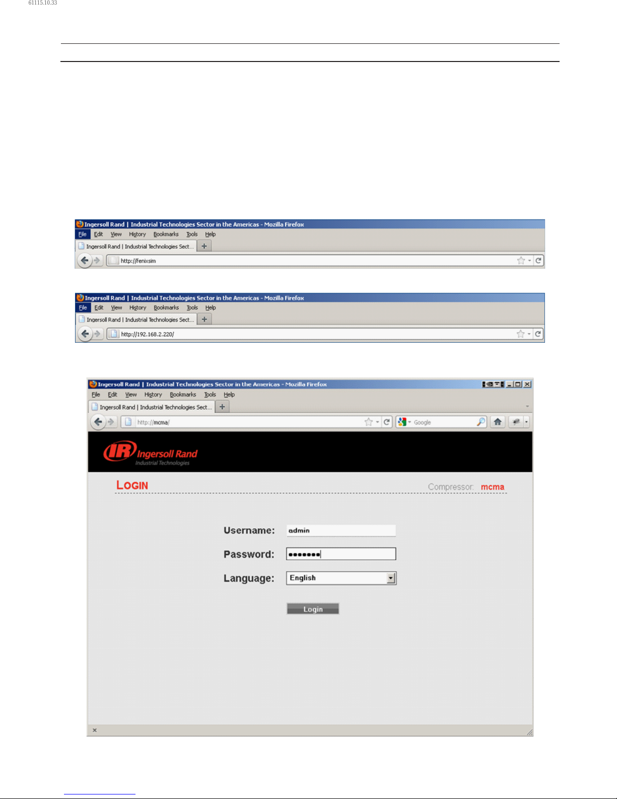
36 80448574 Rev A
LOGIN PROCESS
The server is accessed either by host name or by IP. Accessing by name requires that a router be in the network. During the
installation and commissioning process a network address was assigned to the CONTROLLER by your IT department.
This address may be a static IP (e.g. http://192.168.2.220, recommended) or a DHCP assigned domain name address (e.g. http://
fenixsim.com). A domain name address is a web page address chosen by the user to represent the controller. The domain name
must be approved by your IT department but can generally be any text label you wish. You must have this address before you
can log in to the web pages. See section – Ethernet Conguration.
Please note that Web Pages requires Internet Explorer 8 (or newer) or Mozilla Firefox 5 (or newer). Certain functions may not
behave correctly when using older browser software.
To log in to the web pages you must rst type the address into your browser and then press the enter button. For example,
with a DHCP enabled controller you might type this:
While with a static IP address you might type this:
If the controller is congured correctly you will then see the web pages in your browser. This may take a few seconds
depending on your network connection speed.
•
OPERATING INSTRUCTIONS
61115.10.33
Page 37
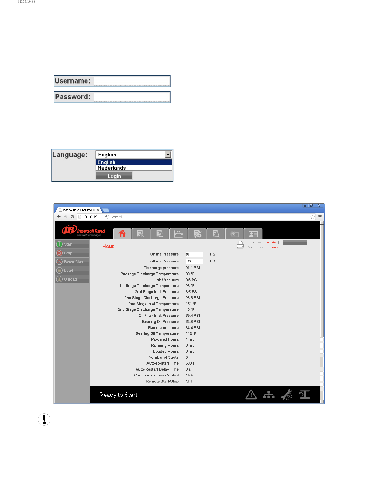
80448574 Rev A 37
The login screen requires the user to enter their username, password and select the language for the web pages. This login
screen will authenticate the user against the type of account. After log in the user can view/modify the data as per the available
access to the user account.
Enter the username and password for log into system and access the web pages.
Type in your user name (case sensitive).
Type in your password (case sensitive).
If the user name or password are incorrect the login page will show a message “Unknown combination of username and
password”.
Click on the dropdown control and select the “Language” from language dropdown control. The full list of languages for the
Xe–145M controller is supported by the web interface. The user may select one language from this list. This selection will be
the language for the web interface after the login is successful.
Select your language from the dropdown list.
Click on “Login” button to continue. Upon successfully logging in you will see the system HOME screen.
Only 5 users can concurrently login to the controller at a time. If another user attempts to login, an error message will
be displayed. “The limit on the number of concurrent users has been reached. Please wait for a user to logo before
trying again.”
Please see below section for default account information, and section “ACCOUNT MANAGEMENT” for more detailed information
about the account management process.
OPERATING INSTRUCTIONS
61115.10.33
Page 38
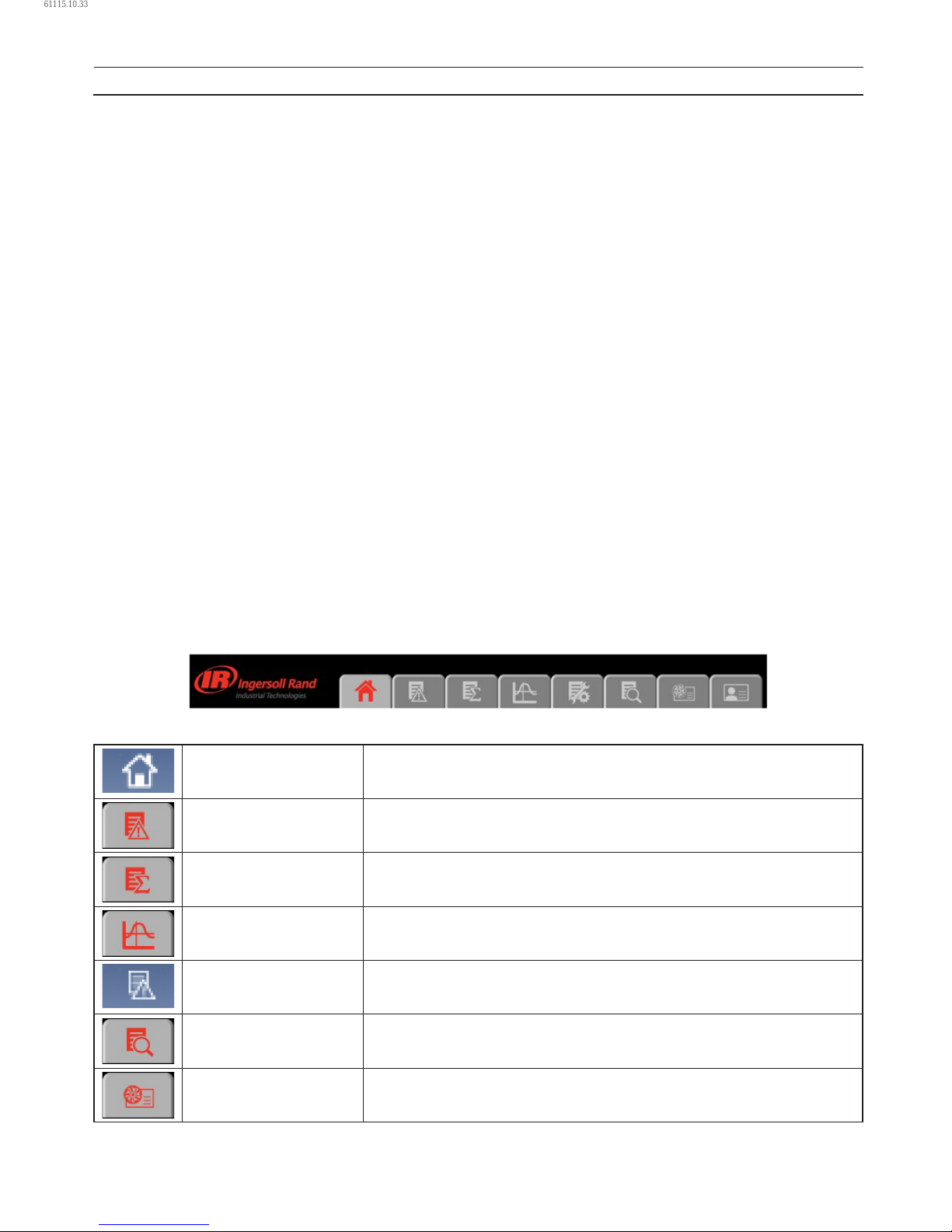
38 80448574 Rev A
DEFAULT ACCOUNTS
The web page software comes with default administrator account. The system administrator can assign users one of three
levels of access (view only, user and administrator) which will determine which functions will be available. For example, only
users with administrator access will be able to create a new user account and view or modify the conguration overview
parameters.
It is highly advised that the administrator change these accounts as soon as feasible to prevent unauthorized access to the
Visualization software. The three level of access rights are as follows:
VIEW : The user is able to view information on all the screens. The user is unable to change any set points or access
to the conguration overview screens.
USER : The user has all rights available to the VIEW access level as well as being able to change setpoints on the
HOME screen and working duration of the maintenance counter. The user is able to manually start, stop, load
and unload the compressors, as well as reset the alarm.
ADMIN : The user has all rights of the VIEW and USER access levels as well as full access to the conguration overview
screens and the account management utility.
Please note that there can be as many as ve (5) maximum users logged into the system at one time, and only one
administrator logged in at one time. Only a user with ADMIN rights will be able to modify these default accounts.
The default account is:
Login : admin
Password: password
Rights : ADMIN
NAVIGATION
Each of the main segments is represented by a tab on the top of web pages. Clicking on the tab will bring you to the screen for
that particular segment.
TAB NAVIGATION
The components of the tab navigation are as follows:
Home Clicking this tab will bring the user to the HOME page. See section HOME PAGE.
Event Log
Clicking this tab will bring the user to the EVENT LOG.
See section EVENT LOG UTILITY.
Performance Log
(Xe–145M Only)
Clicking this tab will bring the user to the PERFORMANCE LOG.
See section PERFORMANCE LOG UTILITY.
Graphing (Xe–145M Only)
Clicking this tab will bring the user to the GRAPHING page.
See section GRAPHING UTILITY.
Maintenance
Clicking this tab will bring the user to the MAINTENANCE page.
See section MAINTENANCE UTILITY.
Inspection Log
(Xe–145M Only)
Clicking this tab will bring the user to the INSPECTION LOG.
See section INSPECTION LOG UTILITY.
Compressor Information
Clicking this tab will bring the user to the COMPRESSOR INFORMATION page.
See section COMPRESSOR INFORMATION.
•
1.
2.
3.
•
•
OPERATING INSTRUCTIONS
61115.10.33
Page 39
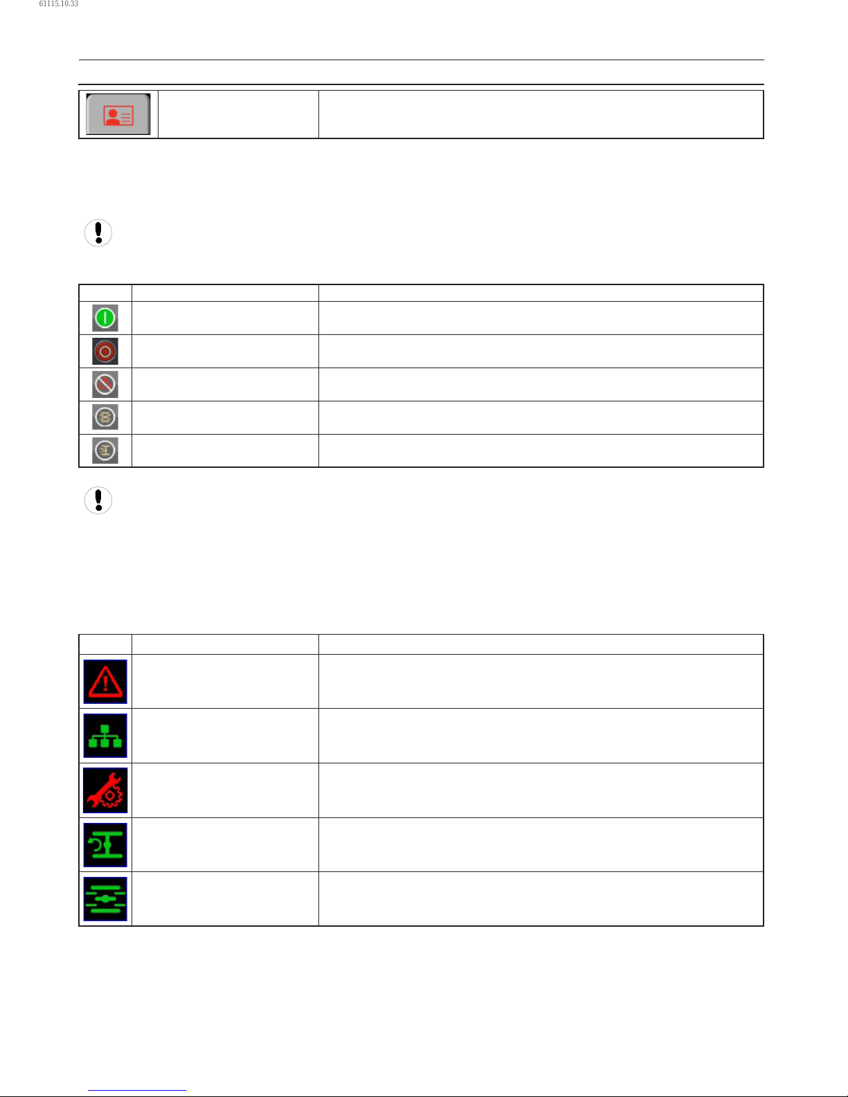
80448574 Rev A 39
Account
Clicking this tab will bring the user to the ACCOUNT page.
See section ACCOUNT MANAGEMENT.
COMMAND BUTTONS
All pages show ve command buttons (Start, Stop, Reset Alarm, Load and Unload), ve dash board icons and current status of
the compressor.
If the current user’s account type does not have the necessary access rights to control the compressor via the web
interface, remote control from the web interface will be disabled at the controller.
“Command Keys” on the web pages command the compressor to perform actions as specied in the following table:
Key Name Function
Start Start the Compressor.
Stop
Stops the compressor. This button should be pressed instead of the E-Stop for
normal stopping operation.
Reset Alarm Clears Warnings and Trips once the condition is corrected.
Load Loads the compressor.
Unload Unloads the compressor.
Remote starting and stopping can be accomplished through the Ethernet Port. Panel power must be on, all utilities
must be running and permissive functions satised in order for the start-up from the web page.
DASHBOARD ICONS
“Dashboard Icons” are intended to be a quick at-a-glance view of system status. These icons are always visible regardless of the
folder/page selected.
The following table lists standard dashboard icons and their denition. Note that the color of these icons changes based on the
state set by the application while running.
Icons Name Description
Alert Illuminates when a Warning (ashes) or Trip (constant on) is sensed.
Remote Control Remote control is enabled.
Service Required
A Service reminder is nearing or has expired (i.e. an air or oil lter needs to be
changed).
Unloaded Compressor is in the unloaded state.
Loaded Compressor is in the loaded state.
•
•
OPERATING INSTRUCTIONS
61115.10.33
Page 40
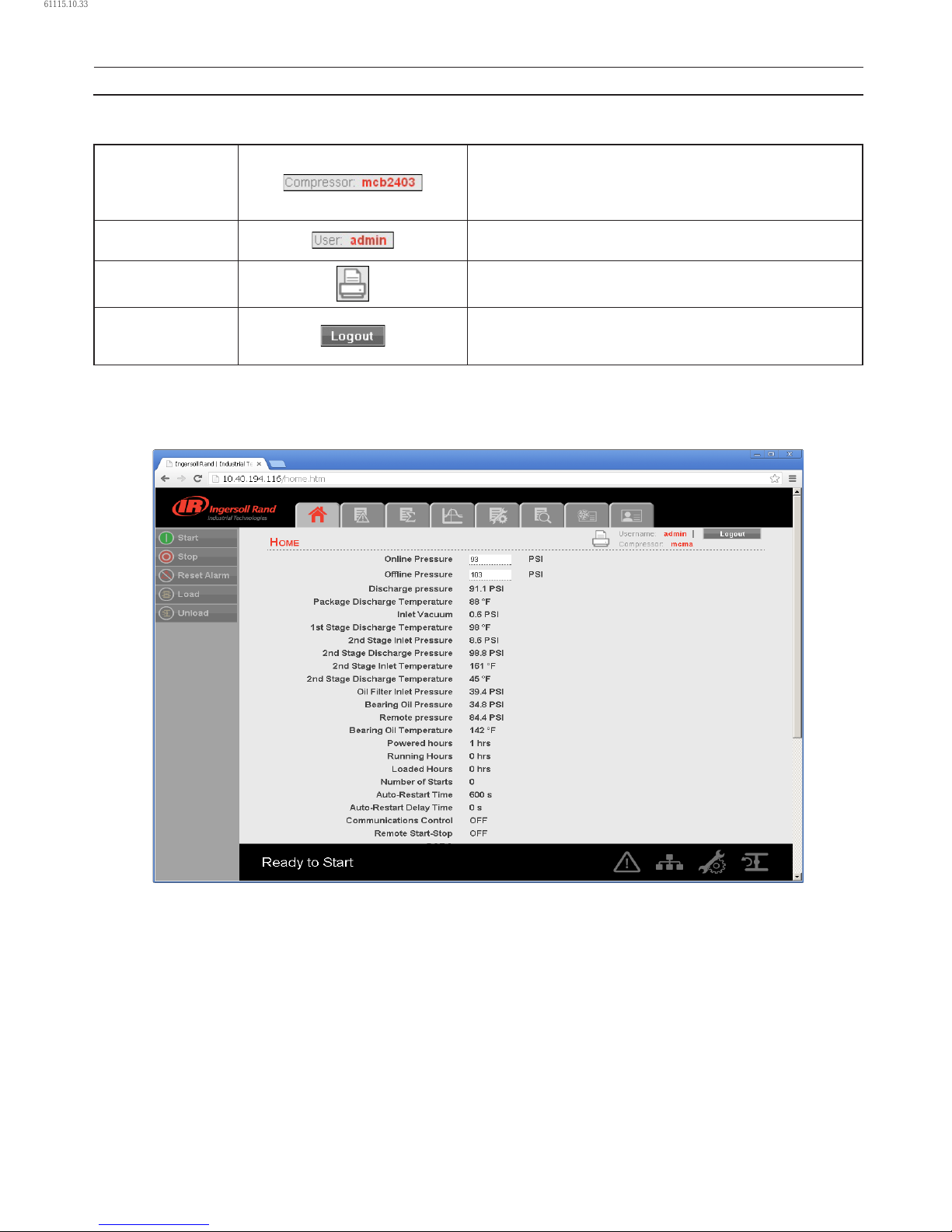
40 80448574 Rev A
Compressor Name, User Name, Print Button and Log Out button are always visible on the right side top of the page, regardless
of the tab selected.
Compressor Name
The user can set the “Compressor Name” from the “Compressor
Information” tab. The user can use this host name as a browser
address for the web pages. A “Compressor Name” is a domain
address to log in the CONTROLLER web pages.
Logged in User
Currently logged in user is shown on the right side top in each
web page.
Print Button
Click on “Print” button, to print the content on existing web
page.
Log Out Button
Click on “Logout” button to terminate the current session.
Clicking this button will log out the current user and return to
the web page login screen.
HOME PAGE
The “HOME” tab shows information about the compressor operating parameters, total power consumption, running hours,
loaded hours, number of starts, etc.
•
OPERATING INSTRUCTIONS
61115.10.33
Page 41
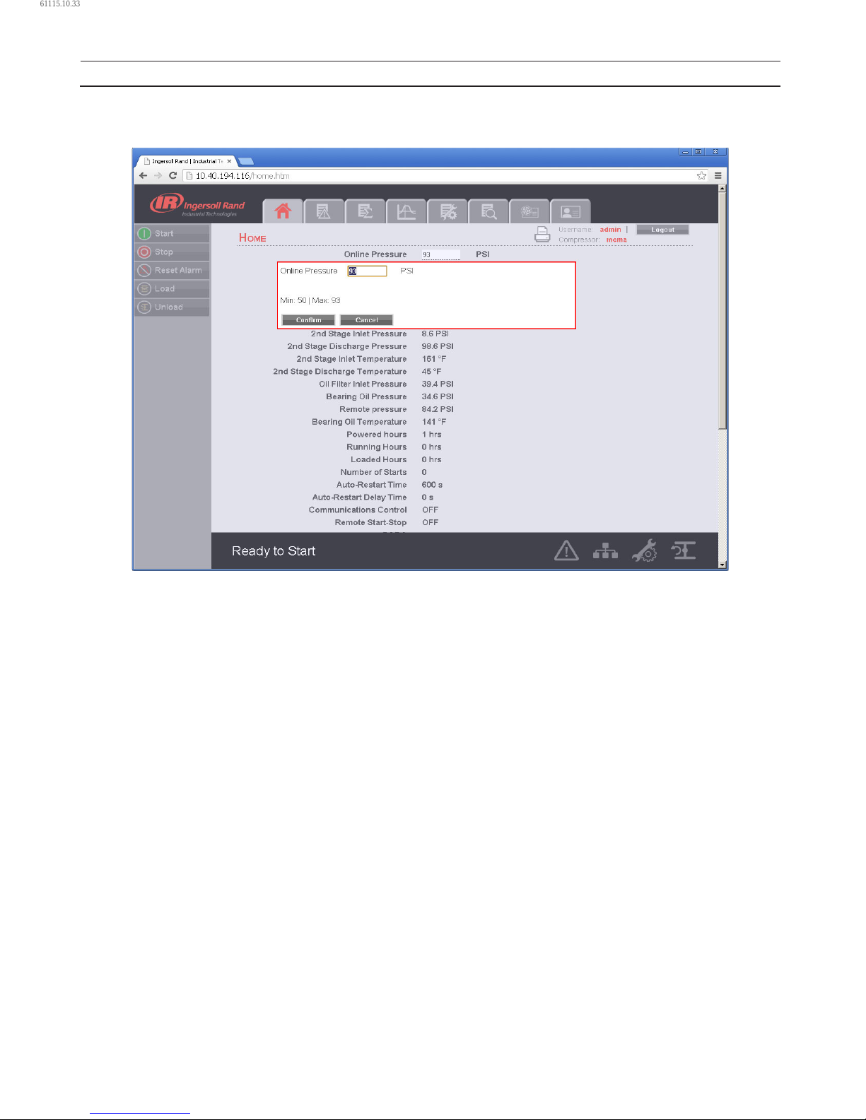
80448574 Rev A 41
Click on the pressure set point value in the white box, to change the “Pressure Set Point” value. Enter the new pressure set point
value and click on “Conrm” button. “Pressure Set Point” is only editable parameter for the “Admin” and “User” type accounts.
The user with “View” type account can’t change these system parameters.
OPERATING INSTRUCTIONS
61115.10.33
Page 42
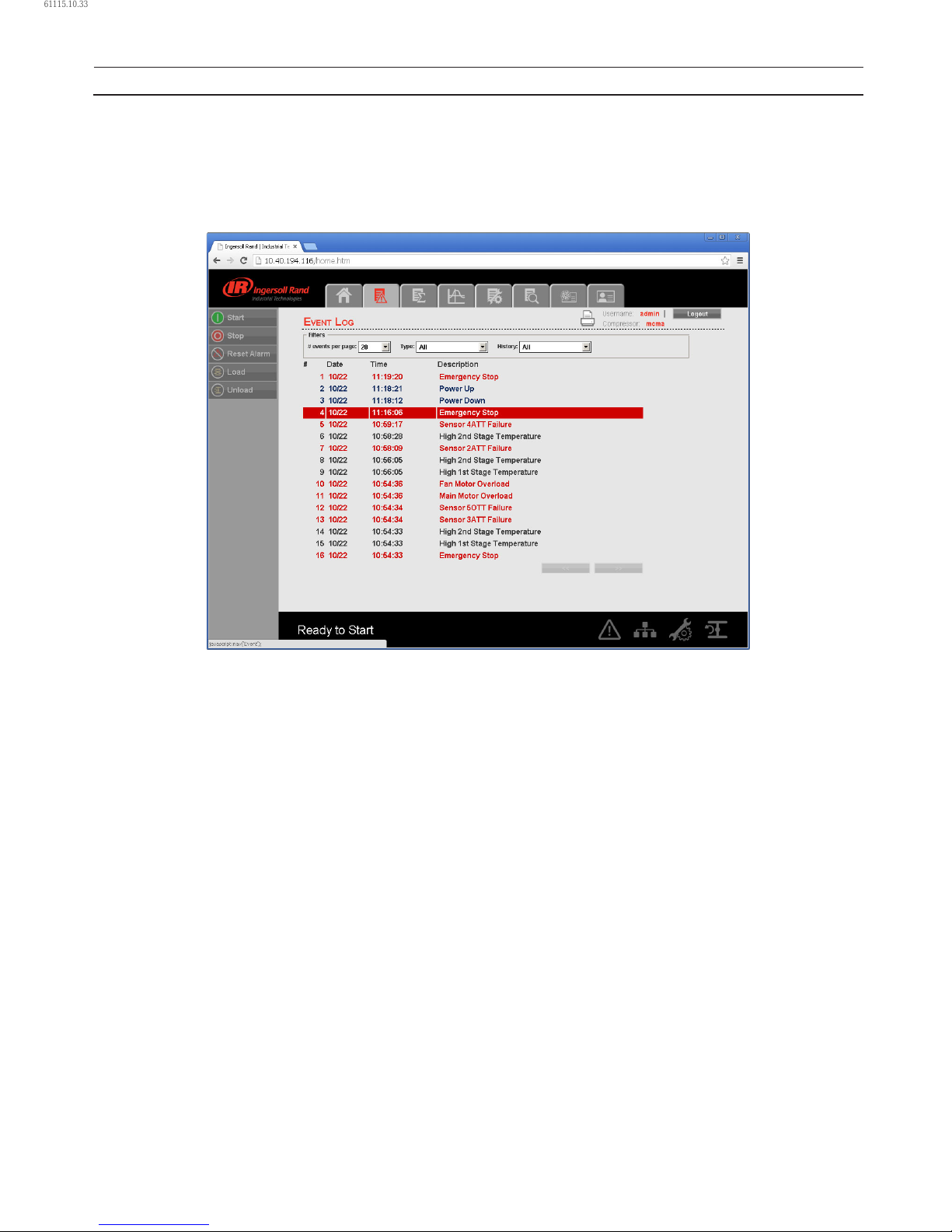
42 80448574 Rev A
EVENT LOG UTILITY
The “EVENT LOG” tab shows the event log from the controller. This tab contains the event log details for the system events,
warnings and trips that have occurred and provides rst-out indication. It also provides controls for ltering the list of events as
shown. Any time an event occurs, the system will send the display to the rst event log page
Each event is added into “EVENT LOG” with a date (mm/dd), time (hh:mm:ss) and the event value. This is the value that
triggered the event. The event labeled as “1” is the newest event.
Click on the dropdown control and select the number of events per page. If the events per page are 20, then previous events
will be available in the next page. Click on the “Next” button will display the previous twenty events.
•
OPERATING INSTRUCTIONS
61115.10.33
Page 43
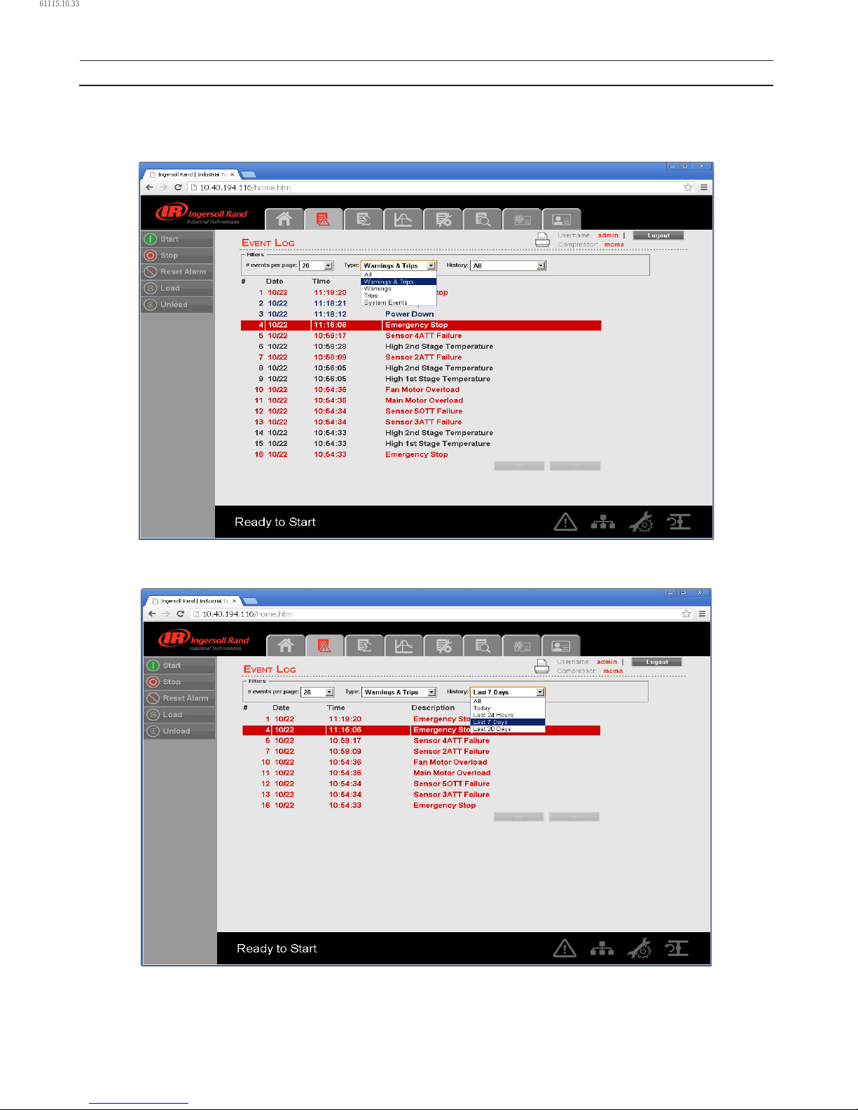
80448574 Rev A 43
The “Event Type” dropdown allows the user to lter the list of events by event type. The user can select the type of event
from the list by clicking the dropdown control. The events recorded and placed into one of three categories: Warnings, Trips/
Shutdowns, and System Events. “EVENT LOG” page highlights all the trips in red text, warnings in yellow text and system events
in the blue text.
The “History” dropdown allows the user to select the option to see the event log history for a selected time period. Click on the
dropdown command and select option “Last 7 Days” to see the event log of last 7 days.
The EVENT LOG will record the last 500 events. Once this 500 event limit has been reached the oldest events will be cleared and
the newest events will appear at the top of the event log.
OPERATING INSTRUCTIONS
61115.10.33
Page 44
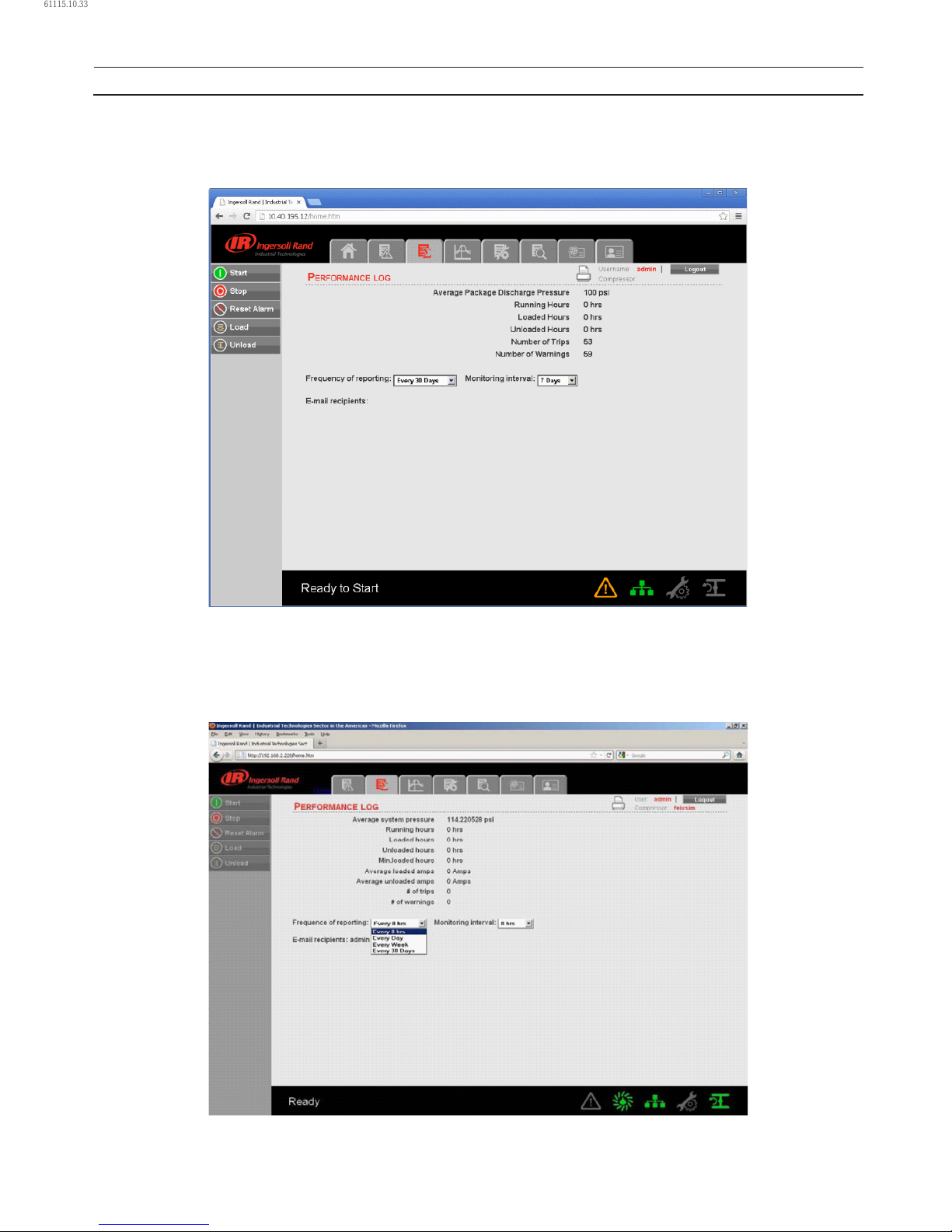
44 80448574 Rev A
PERFORMANCE LOG UTILITY
The “PERFORMANCE LOG” tab shows the performance details and system data for the compressor including Average system
pressure, hour meters, number of trips and warnings. The Performance log report provides a summary of the compressed air
system’s performance for the selected time period.
The “PERFORMANCE LOG” page is divided into two major sections. The top section displays the parameter values. The bottom
section contains the controls for the Performance log.
The “Running Hours” are the amount of time that the compressor has been operating between all start and stop sequence. The
“Loaded Hours” is the amount of time that the compressor has been running and not running unloaded. The “Unloaded Hours”
is the amount of time that the compressor has been running unloaded.
•
OPERATING INSTRUCTIONS
61115.10.33
Page 45
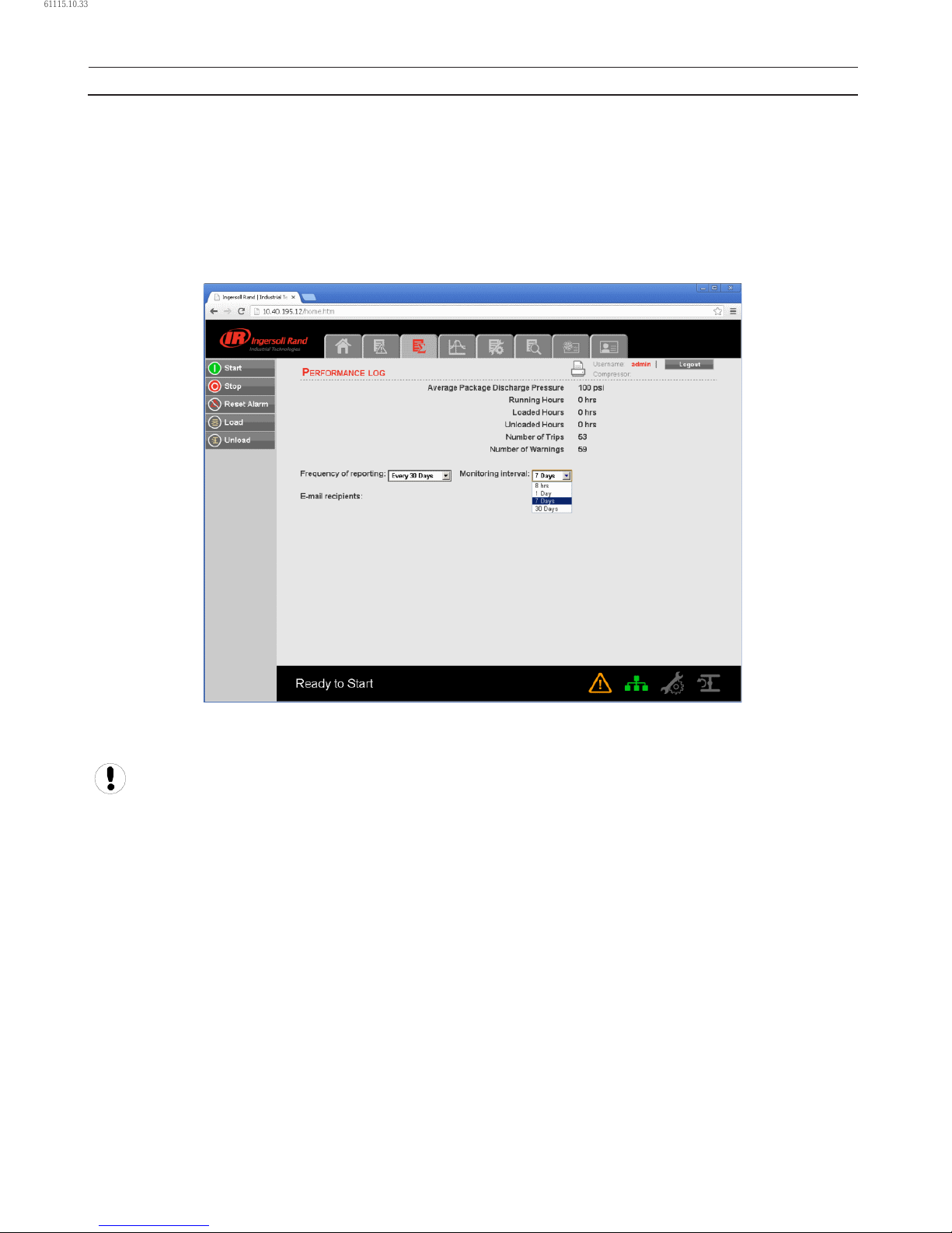
80448574 Rev A 45
The “PERFORMANCE LOG” provides two dropdown controls that allow the user to select sampling of reporting and reporting
settings. The user can change the frequency of reporting and monitoring interval by clicking on the dropdown controls.
The time period of the performance report is selected based on the “Frequency of Reporting”. Click on the dropdown control
and select the “Frequency of Reporting” at which performance log will be emailed to the users that request it via the email
notication section of the “ACCOUNT” page. The default frequency of reporting is “Every 8 hours”. In this case after every 8
hours, the web page application will send the performance log to the user at a specied email account.
The sampling rate of the data capture can be set by the user selection of the “Monitoring Interval”. The “Monitoring Interval”
dropdown control determines the time interval after which parameters will be updated in to the “PERFORMANCE LOG”. All
parameters are stored in a rolling FIFO manner.
User names will be displayed as “E-mail recipients” in the “PERFORMANCE LOG”, if the check box for the same is checked in the
Email notication section of the “ACCOUNT” page.
Refer E-mail notication section of the “ACCOUNT MANAGEMENT” page to change the E-mail address.
OPERATING INSTRUCTIONS
61115.10.33
Page 46
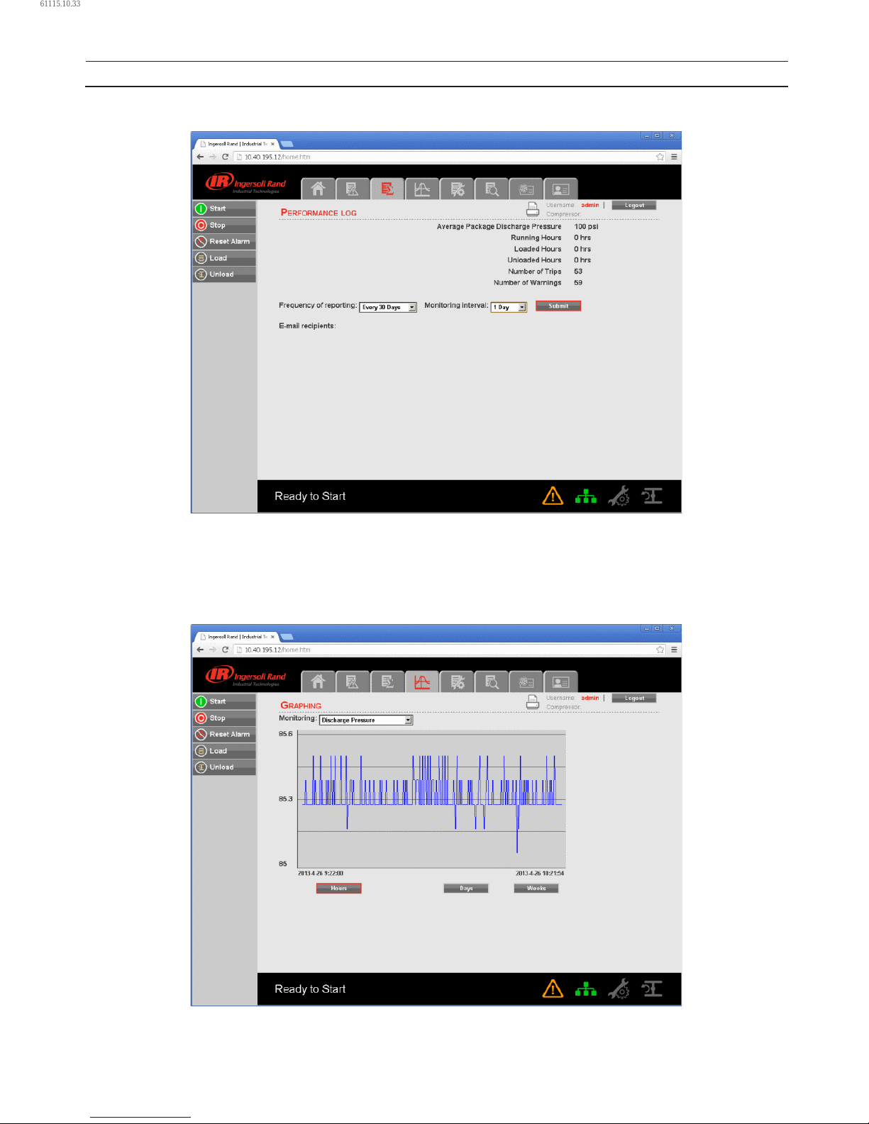
46 80448574 Rev A
Whenever the user changes the “Frequency of reporting” and/or “Monitoring Interval”, a “Submit” button will appear on the
screen. Click on “Submit” button to save the changes.
GRAPHING UTILITY
Click on “GRAPHING” tab to view the data in a graphical format for the selected analog input variable and time duration. The
GRAPHING UTILITY allows the user to plot a graph on hour, day or week basis. The default option is Hours. Activation of a
button will deselect any other button previously selected. When “Hours” has been selected, the X axis will be scaled such that
the span on graph represents duration of 1 hour.
•
OPERATING INSTRUCTIONS
61115.10.33
Page 47
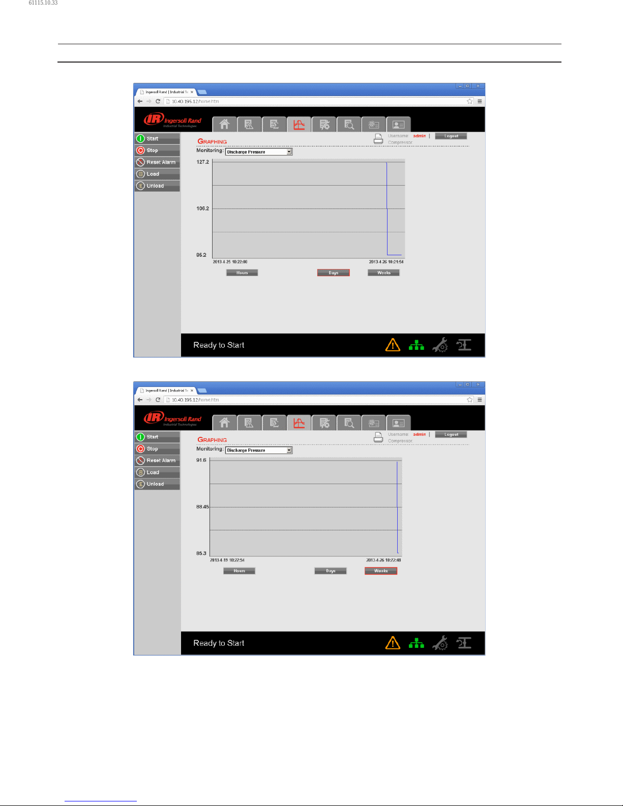
80448574 Rev A 47
When “Days” has been selected, the X axis will be scaled such that the span on graph represents duration of 1 day.
When “Weeks” has been selected, the X axis will be scaled such that the span on graph represents duration of 1 week.
OPERATING INSTRUCTIONS
61115.10.33
Page 48
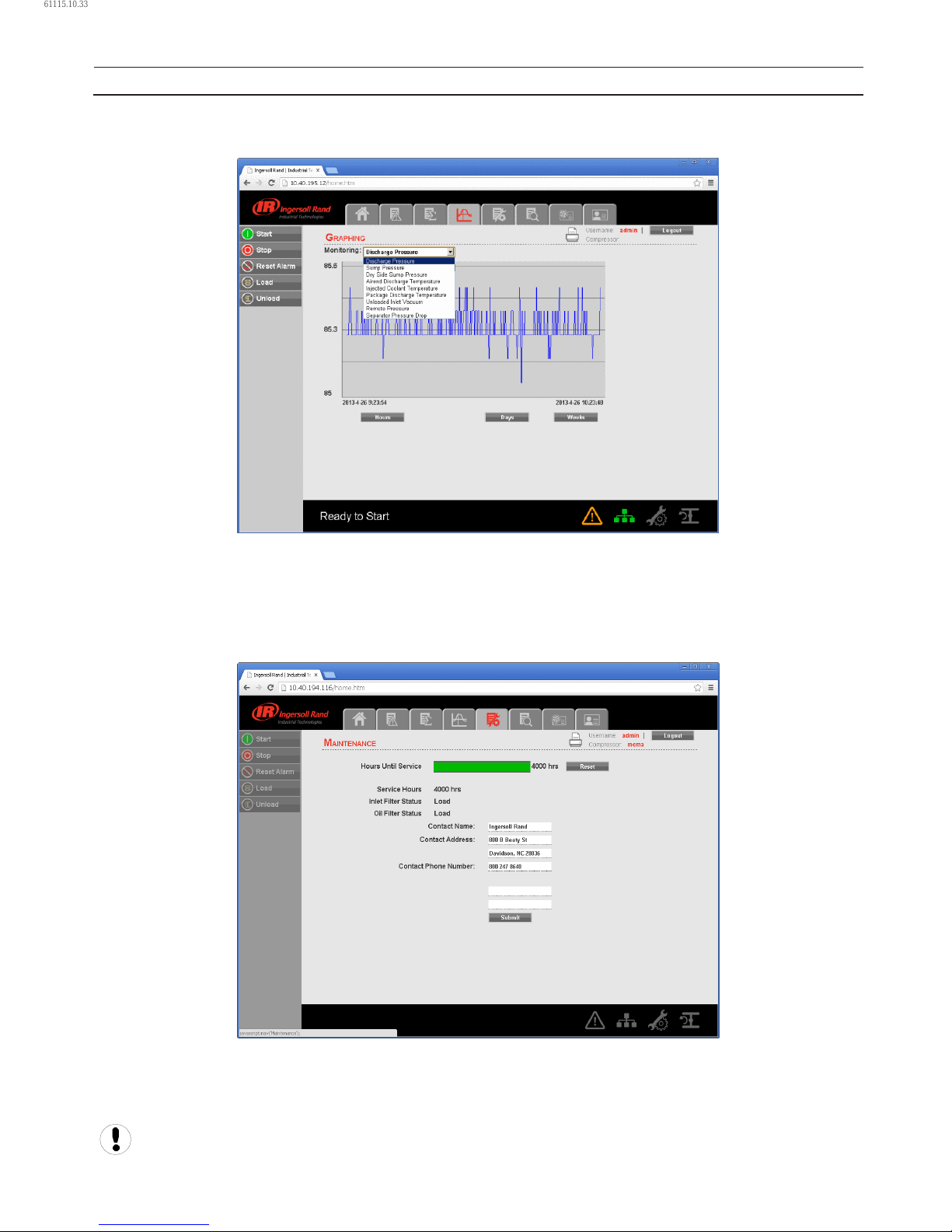
48 80448574 Rev A
The drop down menu allows the user to choose a variable to view data on the graph. Click on the dropdown menu and select
the variable to monitor on the graph. Variables include all analog inputs as well as some calculated variables. The amount of
variables will vary depending on the compressor type and the available options.
By moving the mouse over graph will display the determined value at the position of cursor with the date and time. Due
to performance requirements the data on the real time chart cannot be interacted with directly so this allows the user to
determine the approximate value of any data point.
MAINTENANCE UTILITY
“MAINTENANCE” tab contains the service schedule hours same as shown on the “MAINTENANCE” folder of controller.
This tab provides a service scheduler so that periodic maintenance reminders may be scheduled for consumable parts.
The user can also change the contact address and contact number to call for parts or service. This is the number of the local
Ingersoll Rand representative. Click on “Conrm” button to save the changes.
“Admin” and “User” type accounts can only have an access to change the working duration of the maintenance
counter and Contact details. The “View” type account can’t have an access to change these parameters.
•
OPERATING INSTRUCTIONS
61115.10.33
Page 49
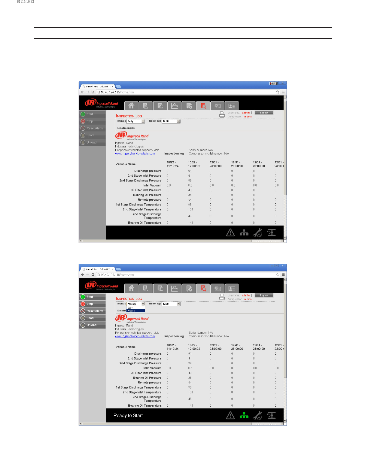
80448574 Rev A 49
INSPECTION LOG UTILITY
The “INSPECTION LOG” tab is intended to record machine data over a xed period of time and a xed rate. Inspection log
contains the controller logged data for the variables at the time of download. The controls section of the “INSPECTION LOG”
shows the user name currently set to receive inspection logs via email, as per the specied time interval and time of the day for
instantaneous data.
Click on the dropdown control and select the “Interval”. The default time interval is “Daily”. If the time interval is “Weekly”, then
the web page application will send the inspection log to the user at a specied email address on weekly basis.
•
OPERATING INSTRUCTIONS
61115.10.33
Page 50
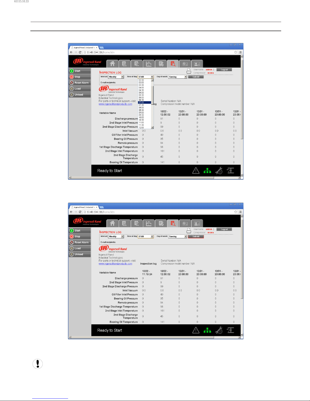
50 80448574 Rev A
Click on the dropdown control and select the “Time of day”. It is shown in a 24 hours clock format.
Click on the “Submit” button to save the changes into the report settings. The user will receive the INSPECTION LOG as per the
selected time interval and time of the day. If the interval is “Daily” and time of day is “09:00” then the web page application will
send inspection logs via email, everyday at 9:00 AM.
The user name will be displayed as “E-mail recipients” in the “INSPECTION LOG”, if the check box for the same is checked in the
Email notication section of the “ACCOUNT” page.
Refer E-mail notication section of the “ACCOUNT” page to change the E-mail address.
OPERATING INSTRUCTIONS
61115.10.33
Page 51
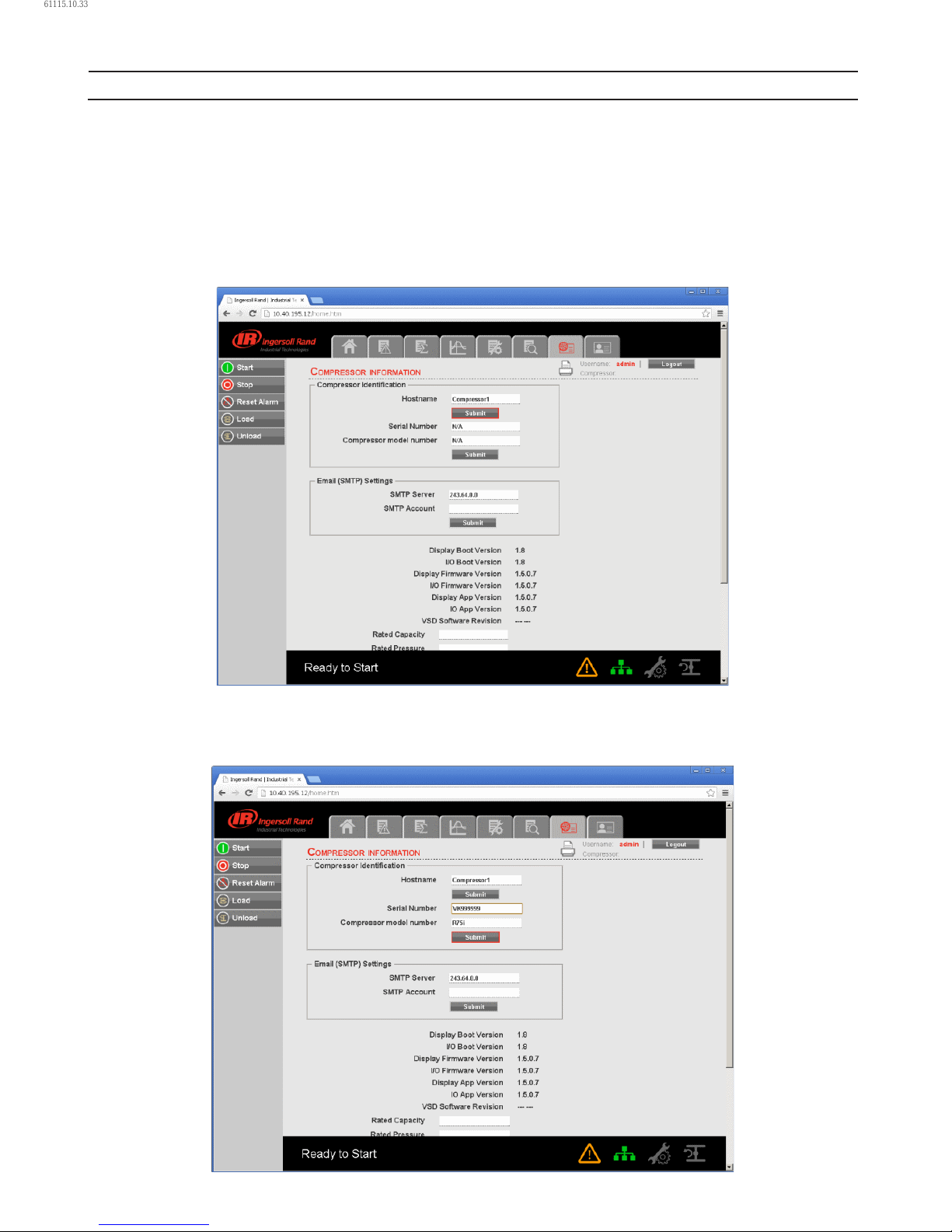
80448574 Rev A 51
COMPRESSOR INFORMATION
The “COMPRESSOR INFORMATION” tab contains the compressor name, compressor model number, compressor serial number,
rated capacity, rated pressure, rated voltage, running current, starting current, power requirement, motor service factor,
measuring units and Email (SMTP) settings.
COMPRESSOR IDENTIFICATION
The “Host Name” is shown as a “Compressor Name” on the right side top of each web page. The user can use this domain name
as a web page browser address to access the web pages. To change the existing host name, enter the new hostname in the
white box and click on “Submit” button.
Once the user will submit the new host name, the compressor name will be changed automatically on the next login.
Enter the “Serial Number” and “Model Number” as per the compressor nameplate, and click on “Submit” button to save these
compressor details.
•
•
OPERATING INSTRUCTIONS
61115.10.33
Page 52
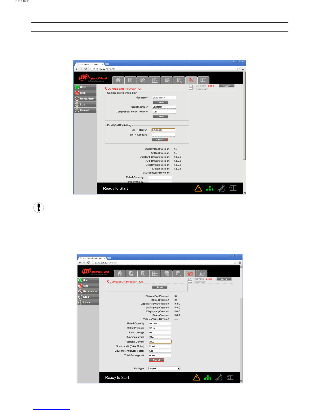
52 80448574 Rev A
EMAIL (SMTP) SETTINGS
If email notications are to be used, the SMTP server settings must be obtained from IT and entered in this location. Enter the
“SMTP Server” and “SMTP Account” and then click on “Submit” button to save the SMTP settings.
User account with access level “Admin” can only have an access to change the parameters in “Compressor
Identication” and “Email (SMTP) Settings” blocks. User account with access level “User” and “VIEW” cannot have an
access to change these parameters.
COMPRESSOR DETAILS
Enter the rated capacity, rated pressure, rated voltage, running current, starting current, nominal power in kW and main motor
service factor as per the data available in the compressor datasheet.
Click on the “Submit” button to save the compressor details.
•
•
OPERATING INSTRUCTIONS
61115.10.33
Page 53
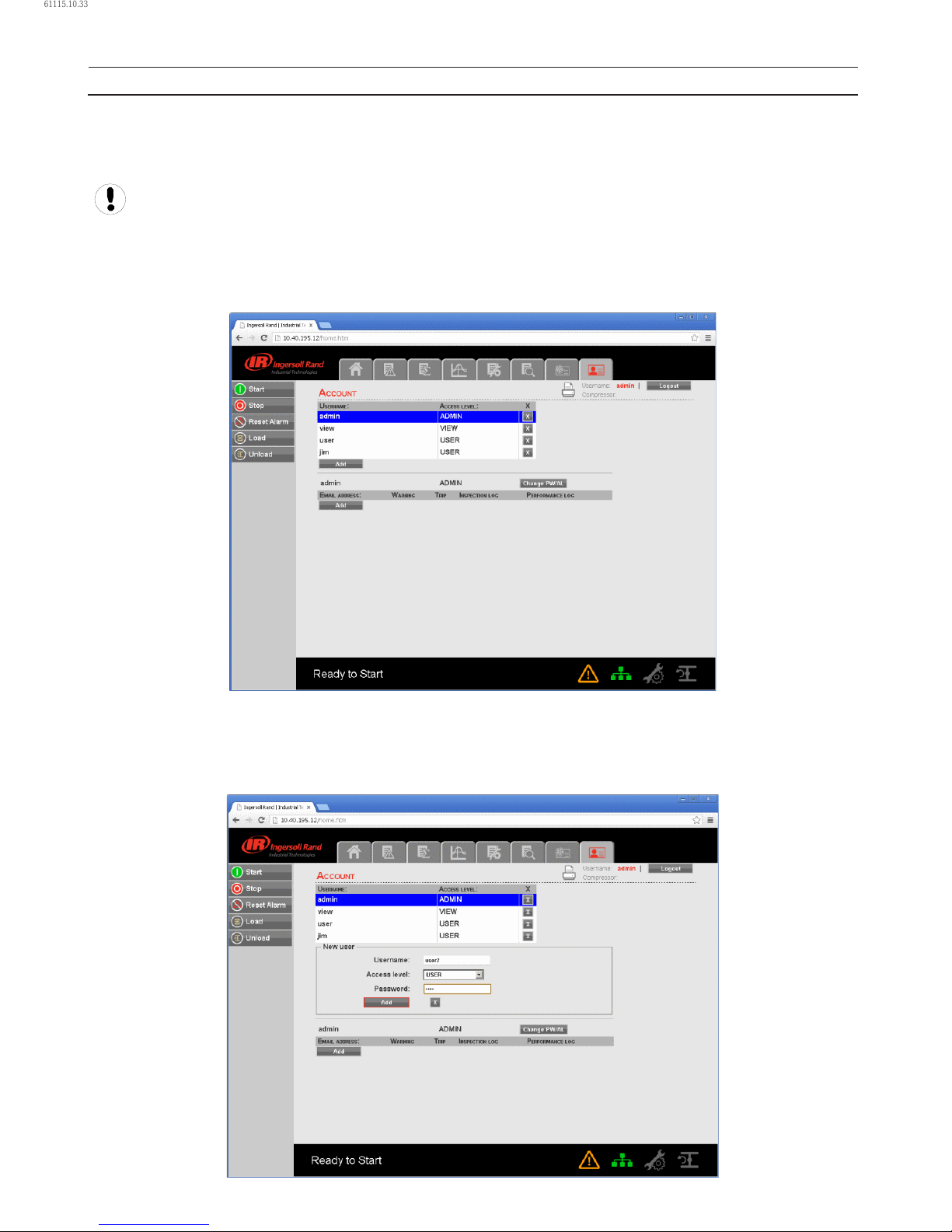
80448574 Rev A 53
UNIT TYPE
Click on the dropdown control and select the measurement unit type for the compressor parameters. Default unit type is
“English”.
User account with access level “Admin” and “User” can only have an access to change these compressor parameters.
User account with access level “VIEW” can only monitor the data and the user can not have an access to change these
parameters.
ACCOUNT MANAGEMENT
The administrator can create any number of users desired and assign each user one of three levels of access, as well as
assigning email notications to various events that may occur.
ADD ACCOUNT
The “ACCOUNT” tab shows the list of accounts that currently exist which are listed by user name and access rights. Clicking on
an account will highlight that account in blue color. Click on “ADD” button to add an account with a specied access level for
the web page application. Enter the ADMIN password to proceed.
•
•
•
OPERATING INSTRUCTIONS
61115.10.33
Page 54
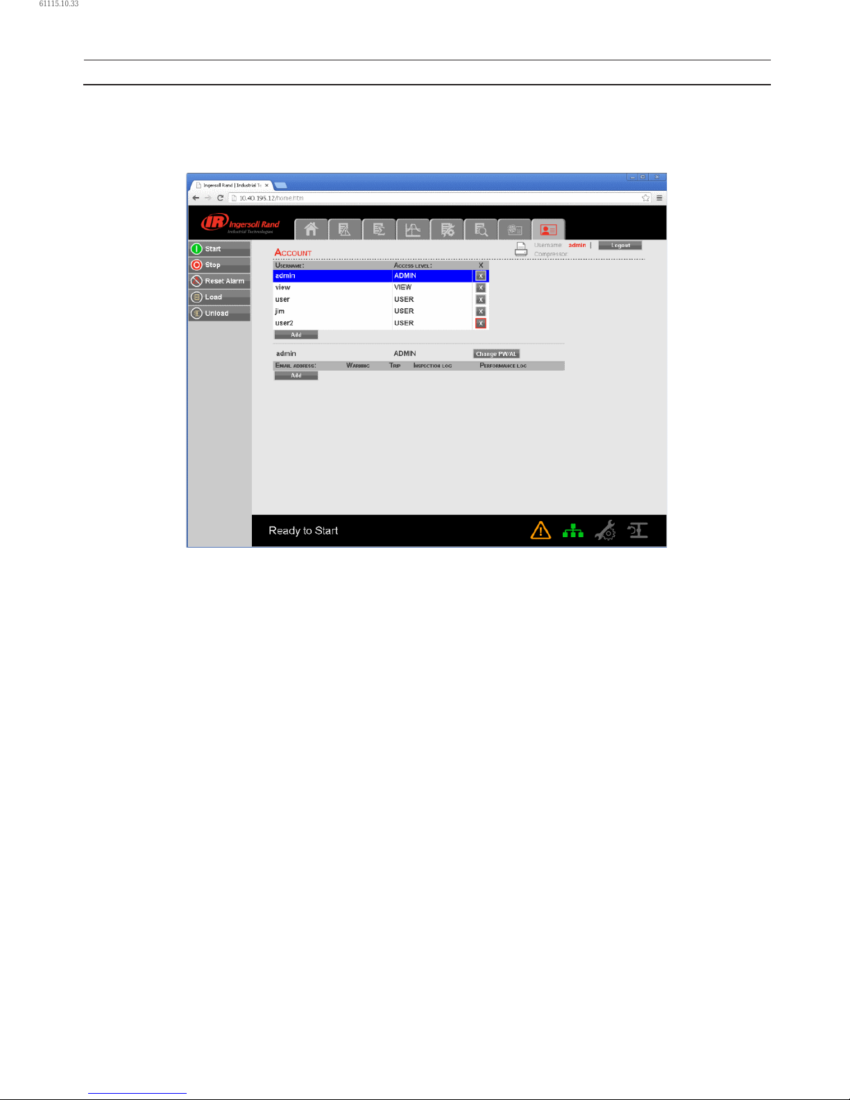
54 80448574 Rev A
OPERATING INSTRUCTIONS
To generate a new user account; enter the unique username, password and select the user access rights. Click on “Add Account”
button will add the new user account into the list of user accounts. Only a user with “ADMIN” rights will be able to make a new
account or remove the existing accounts.
Select the user account from the list and click on “X” button to delete the selected user account.
61115.10.33
Page 55
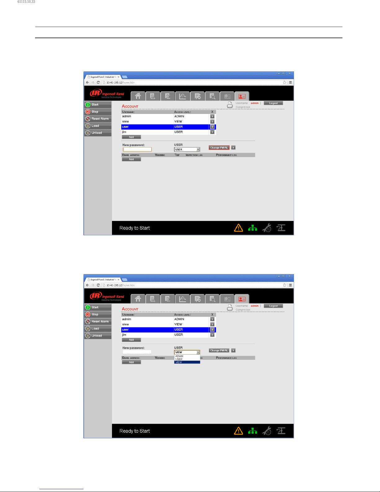
80448574 Rev A 55
OPERATING INSTRUCTIONS
MODIFY THE ACCESS LEVEL
User account with access level “ADMIN” can also change the access level of existing user accounts. To change the access level or
password of an existing user account, select the user account from the list and click the Change PW/AL button.
Click on the dropdown control and choose the new access level for selected user account. Again, click on “Change PW/AL”
button to save the changes in access level or password for selected user account.
Set the email address settings for the user by clicking on the “Add” button in the email list. Then type in the email address and
check the boxes for the type of alerts the user should receive. When nished, press the “Submit” button.
•
61115.10.33
Page 56
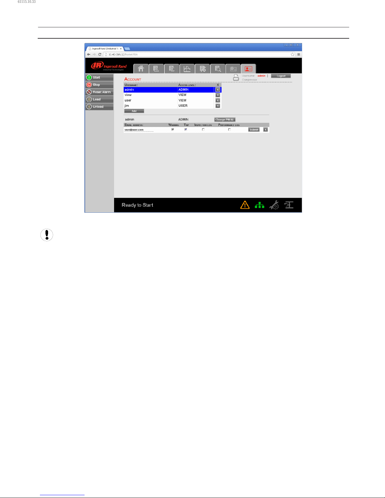
56 80448574 Rev A
OPERATING INSTRUCTIONS
User account with access level “Admin” can only have an access to make a new account or modify the access level
of these accounts. User account with access level “User” and “VIEW” can’t have an access to make a new account or
modify the user accounts.
61115.10.33
Page 57
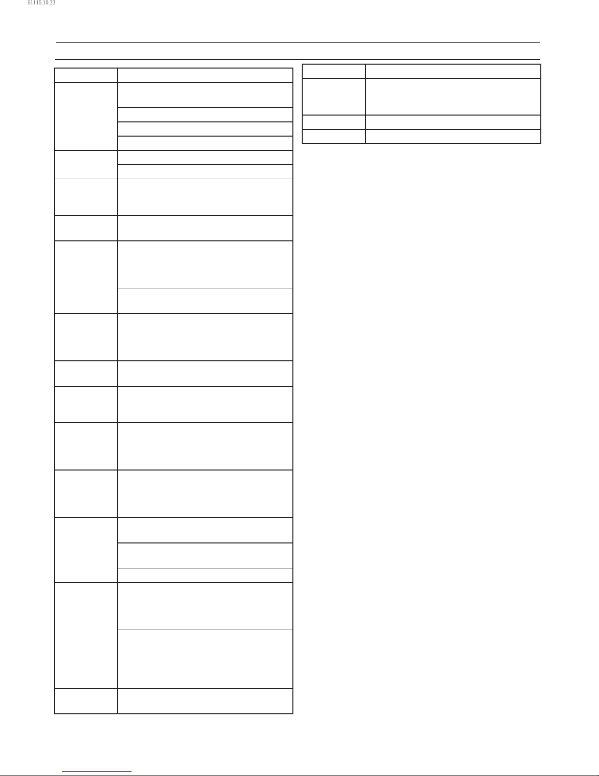
80448574 Rev A 57
MAINTENANCE
PERIOD MAINTENANCE
Daily Check the lubricating oil level and replenish
as necessary.
Check the oil lter pressure dierential.
Check the air lter pressure dierential.
Check the condensate drain functionality.
First
150 hours
Change the oil lter element.
Clean the condensate strainers.
1 month AC Check the cooler(s) for build-up of
foreign matter.
Clean if necessary by blowing out with air.
Every
1000 hours
Analyse Food-grade Lubricant (Ultra FG).
Each
3 months
Operate the safety valves manually to verify
that the valve mechanism is functioning
correctly and that a small amount of air is
released.
Check all hoses for signs of deterioration,
cracks, hardening etc.
2000 hours Lubricate the main motor drive end bearing.
Lubricate the main motor non-drive end
bearing.
Analyse Premium Coolant (Ultra/Ultra EL).
4000 hours Rebuild condensate solenoid valves using
eld kits.
4000 hours /
6 months
Inspect the blowdown silencers and replace
if necessary.
Clean the gearcase breather.
6 months Check the calibration of the pressure
transducers.
Change the air lter element (replace more
frequently if local conditions require).
Every
6000 hours
Replace Food-grade Lubricant
(Ultra FG).
NOTE: Change the oil lter element if
replacing Food-grade Lubricant.
8000 hours Inspect the starter contactors, replace if
required.
Replace check valve seat and spring using
eld kit.
Rebuild blowdown valve using eld kit.
8000 hours /
1 year
Clean the condensate strainers. Change the
oil lter element.
Replace Premium Coolant (Ultra)
[8000 hours or every 2 years].
Fully inspect condensate separators, all
external surfaces, and ttings.
Report any excessive corrosion, mechanical
or impact damage, leakage or other
deterioration.
1 year Remove the safety valves from compressor,
inspect and re-calibrate.
PERIOD MAINTENANCE
16000 hours Rebuild hydraulic cylinder using eld kit.
Replace Extended-life Premium Coolant
(Ultra EL) [16000 hours or every 3 years].
4 years Replace all hoses.
40000 hours Replace discharge check valve.
ROUTINE MAINTENANCE
This section refers to the various components which require
periodic maintenance and replacement.
The SERVICE/MAINTENANCE CHART indicates the various
components’ descriptions and the intervals when
maintenance has to take place. Oil capacities, etc., can be
found in the PRODUCT SPECIFICATION SHEET.
Compressed air can be dangerous if incorrectly handled.
Before doing any work on the unit, ensure that all pressure
is vented from the system and that the machine cannot be
started accidentally.
Ensure that maintenance personnel are adequately trained,
competent and have read the Maintenance Manuals.
Prior to attempting any maintenance work, ensure that:–
all air pressure is fully discharged and isolated from the
system. If the automatic blowdown valve is used for this
purpose, then allow enough time for it to complete the
operation.
the machine cannot be started accidently or otherwise,
by posting warning signs and/or tting appropriate
anti–start devices.
all residual electrical power sources (mains and battery)
are isolated.
Prior to opening or removing panels or covers to work
inside a machine, ensure that:–
anyone entering the machine is aware of the reduced
level of protection and the additional hazards, including
hot surfaces and intermittently moving parts.
the machine cannot be started accidentally or otherwise,
by posting warning signs and/or tting appropriate
anti–start devices.
Prior to attempting any maintenance work on a running
machine, ensure that:–
the work carried out is limited to only those tasks which
require the machine to run.
the work carried out with safety protection devices
disabled or removed is limited to only those tasks which
require the machine to be running with safety protection
devices disabled or removed.
all hazards present are known (e.g. pressurised
components, electrically live components, removed
panels, covers and guards, extreme temperatures, inow
and outow of air, intermittently moving parts, safety
valve discharge etc.).
appropriate personal protective equipment is worn.
loose clothing, jewellery, long hair etc. is made safe.
•
•
•
•
•
•
•
•
•
•
•
61115.10.33
Page 58
58 80448574 Rev A
warning signs indicating that Maintenance Work is in
Progress are posted in a position that can be clearly seen.
Upon completion of maintenance tasks and prior to
returning the machine into service, ensure that:–
the machine is suitably tested.
all guards and safety protection devices are retted.
all panels are replaced, canopy and doors closed.
hazardous materials are eectively contained and
disposed of.
WARNING
Do not under any circumstances open any drain valve or
remove components from the compressor without rst
ensuring that the compressor is FULLY SHUT–DOWN,
power isolated and all air pressure relieved from the
system.
AIR FILTER CHANGE PROCEDURE
A warning message will appear if the air lter pressure drop
exceeds 0,048 bar (0,7 psi). To check the condition of the inlet
lter, run the compressor in load mode and select “INLET
VACUUM” from the current status screen using the up and
down arrows. Change if equal to or above 0,048 bar (0,7 psi).
To change the inlet lter, remove the appropriate enclosure
panel on the front of the machine.
Check the retaining cap for dirt and debris and wipe
clean.
Unclip the retaining cap and withdraw the old element.
Fit the new element and ret the retaining cap.
OIL CHANGE
To change the oil, the oil should be warm for more eective
drainage. Remove the right end enclosure panel. Remove
the pipe plug from the oil drain connection in the rear of
the baseplate. Place a suitable drain pan under the drain
connection and open the valve.
Dispose of waste lubricant according to local regulations.
When the gearcase is empty, close the valve and replace the
pipe plug. Change the oil lter and allow the oil to drain from
the oil cooler as well.
Unscrew the oil ller cap and add oil until the level reaches
the top of the gearcase sight glass.
Start the compressor and run in unload mode. Check the oil
lter and oil drain valve for leaks. Select ”BEARING OIL PRESS”
from the current status screen to insure that adequate oil
pressure has been attained. Inspect the gearcase sight glass,
the correct oil level for the sump during operation is 3/4 to
4/4 full. Some amount of foaming in the sight glass is normal.
The oil level is interpreted as the level in the sight glass
below the top foam, where a line of separation can be seen. If
additional oil is required, stop the compressor and add oil as
needed.
•
•
•
•
•
•
1.
2.
3.
•
OIL FILTER
Change oil lter after every 8,000 hours or less as required
(see checking procedure below).To check the condition of
the oil lter, the compressor must be running and the oil
temperature must be greater than 49 °C (120 °F). With these
conditions met select ”OIL FILTER PRESS DROP” from current
status screen. If ”OIL FILTER PRESS DROP is less than 0,9 bar
(13 psi) then the oil lter does not need service. If the warning
light is on and ”CHANGE OIL FILTER” warning is displayed,
then the oil lter should be replaced.
Position the empty drain pan under the oil lter, loosen the
lter housing. Remove the element from the housing. Wipe
the sealing surface of the lter adaptor with a clean, lint–free
cloth. Remove the replacement lter from its protective
package. Apply a small amount of clean oil on the rubber seal
and install the element. Screw the element on until the seal
makes contact with the seat on the adaptor head. Tighten the
lter a further 1/2 to 3/4 of a turn.
Start the compressor, check for leaks and check the oil level.
GEARCASE BREATHER
To service the gearcase breather, remove the right end panel.
Remove the breather cover by unscrewing the four retaining
screws. Remove all of the breather media and clean with a
suitable solvent. Allow the media to dry. Re–install the media,
the cover, and the enclosure panel.
CONDENSATE DRAIN FUNCTIONALITY
To verify the functionality of the condensate drains, simply
observe the timed operation of each. Each drain should open
at least every 2 minutes while the compressor is loaded. (The
intercooler drain exhausts at a much lower pressure than the
aftercooler).
Oil free condensate can be disposed of via a sewer drain.
CONDENSATE STRAINERS
In order to service the condensate strainers (both inter-stage
and discharge), the strainer service valves preceding the
strainers should be closed. Remove the screens from the
strainers, while noting the direction. Clean any debris from
the screens and reinstall. Open the strainer service valves.
AIREND BEARINGS
Airend bearings are lubricated by the compressor lubricating
oil and require no maintenance.
COMPRESSOR MODULE INPUT SHAFT SEAL
REPLACEMENT
Remove the main motor, observing all safety precautions
in Section A of this manual, utilising appropriate lifting
gear as recommended and following established safe
working practices.
Pull the compressor coupling half o the shaft.
•
•
•
•
•
•
1.
2.
MAINTENANCE
61115.10.33
Page 59
80448574 Rev A 59
Remove the 4 bolts retaining the seal housing and screw
2 of them to remove the housing complete with seal.
Remove the old seal from the housing.
Remove the old wear sleeve from the input shaft.
Clean the seal housing, input shaft, wear sleeve inside
diameter and seal outside diameter (Absolutely grease
free).
Apply Loctite 620 to the sleeve and shaft journal. Install
the sleeve ensuring that the face of the sleeve is 4 mm
from the shoulder on the shaft. Wipe excess Loctite.
Apply Loctite 524 to the seal outer diameter and
install into the seal housing with lip facing towards the
compressor.
Allow to cure for 2 hours.
Clean the gasket face of the seal housing and gearcase
housing (absolutely grease free).
Apply Loctite 510 to the gasket face on the seal and
gearcase housings.
Lubricate the outside diameter of the installation tool
with clean oil. Tool CPN 39307848.
Using the seal installation tool, slide the seal housing
into place on the bearing housing, being careful not to
tilt the housing and seal. Apply axial pressure to the end
of the installation tool while the seal leaves the tool and
enters the wear sleeve. The seal will slip between the tool
and the sleeve if pressure is not applied.
Apply Loctite 242 to the 4 seal housing bolt threads and
tighten.
Heat the coupling half to 177 °C (350 °F) for 1,5 hours
and re–t the coupling and spacer to the shaft.
Allow 24 hours for all Loctite applications to cure before
restarting the machine.
MOTOR BEARINGS
Clean the area around the inlet and outlet plugs before
3.
4.
5.
6.
7.
8.
9.
10.
11.
12.
13.
14.
15.
16.
•
removing the plugs. Add the specied quantity of
recommended grease using a hand lever gun. Replace the
inlet plug, run the machine for 10 minutes and then replace
the outlet plug.
MOTOR BEARING LUBRICANT SPECIFICATION
50Hz Use High Temperature Grease Esso Unirex N3
(CPN:92844729).
60Hz As per nameplate. Chevron Black Pearl#2. Chevron SRI2.
CAUTION
Do not over pack the motor bearings with grease as this
may lead to motor failure.
CAUTION
Ensure dirt and/or other contaminants are not
introduced into the bearing during the greasing process.
CLEANING/INSTALLING PACKAGE PRE-FILTER [90-
160Kw(125-200Hp)NEW ENCLOSURE ONLY]
Unlatch the two 1/4 turn latches and open the intake
panle (panel is hinged).
Remove the six wing nuts and at washers.
Remove the lter grill.
Pull out the lter element.
Center the new element over the package intake
opening. Also note that the lter is washable with mild
detergent.
Push the lter over the grill studs so that the studs poke
through the lter media.
Install the lter grill.
Install the six wing nuts and at washers.
Close the intake panel and latch.
•
•
1.
2.
3.
4.
5.
6.
7.
8.
9.
MAINTENANCE
61115.10.33
Page 60
60 80448574 Rev A
TROUBLESHOOTING
PROBLEM REMEDY
Compressor fails to
start.
110/120V CONTROL VOLTAGE NOT AVAILABLE.
Check the fuse. Check the transformers and wiring connections.
EMERGENCY STOP.
Rotate emergency stop button to disengage, and press reset button twice.
STARTER FAULT (1SL OR 2SL).
Inspect starter auxiliary contacts, connections and wiring.
Inspect contactors. Replace if defective.
MAIN (OR FAN) MOTOR OVERLOAD.
Manually reset main (or fan) motor overload relay, and press reset button twice.
Run unit and compare actual amps with name plate for possible action.
SENSOR FAILURE.
Check for defective sensor, bad sensor connection or broken sensor wires.
Xe CONTROLLER 24VAC CONTROL VOLTAGE NOT AVAILABLE.
Check fuses.
DISPLAY PANEL AND POWER ON LIGHT DOES NOT ILLUMINATE.
Check wiring. Verify 24VAC is within voltage tolerance (±15%).
Compressor shuts
down.
HIGH 2ND STAGE TEMPERATURE
Ensure that installation area has adequate ventilation. Fan side of intercooler may be dirty or plugged,
clean as required.
INLET RESTRICTION.
Check for obstructions in air intake system. Verify that 2nd stage discharge temperature in the unload
reduces slowly from the temperature in the load mode. If the unload temperature is greater, adjust
the inlet/unloading valve.
(Note: The inlet vacuum under the inlet/unloading valve should be approximately 0.87 bar (13 psi) in
the unload mode).
LOW BEARING OIL PRESSURE.
Check oil level in gearcase sight glass. The level should be between ¾ to ⁄ full.
Check complete machine for oil leaks.
Oil lter may be dirty or plugged. Replace lter.
Remove tube on discharge side of oil relief valve to determine if valve is leaking. Replace valve if
leaking.
Remove ex line from vent side of hydraulic cylinder. If a large amount of oil exits the cylinder,
overhaul hydraulic cylinder valve assembly.
Remove oil pump to inspect tang drive. Replace pump and/or drive assembly if found defective.
HIGH l/C PRESSURE.
Check for air leaks between 2nd stage discharge ange and discharge check valve.
Check discharge safety relief valve for leakage. Replace valve if leaking.
Check discharge manual condensate valve to ensure that it is closed.
HIGH 1ST STAGE TEMPERATURE.
Ensure that installation area has adequate ventilation.
Ensure that cooling fan is operating.
Ensure that inlet control hydraulic cylinders is fully stroking when compressor is loaded. Replace inlet/
unloading assembly if it is found defective.
HIGH BEARING OIL TEMPERATURE.
Ensure that installation area has adequate ventilation.
Fan side of oil cooler may be dirty. Clean as required.
Thermostat element in oil temp control valve may be defective.
61115.10.33
Page 61
80448574 Rev A 61
PROBLEM REMEDY
Compressor shuts
down.
HIGH I/C AIR TEMPERATURE.
Ensure that installation area has adequate ventilation.
Fan side of intercooler may be dirty or plugged. Clean as required.
HIGH 2ND STAGE PRESSURE HIGH LINE AIR PRESSURE.
Check for blockage or obstruction in air side of aftercooler, discharge moisture separator or discharge
check valve.
Ensure that air network has adequate receiver volume.
Ensure that isolation valve is fully open.
Ensure that discharge pipe is adequately sized.
STARTER FAULT (1SL OR 2SL).
Check for loose wires or faults on the control circuit. Inspect starter connectors.
MAIN MOTOR OVERLOAD.
Check for loose wires. Check supply voltage. Check heater size.
FAN MOTOR OVERLOAD.
Check for loose wires. Check supply voltage. Check heater size.
Check for obstructions at machine inlet and outlet openings.
HIGH 1/C CONDENSATE.
Check intercooler condensate drain system including strainer.
Check valve and 6SV. Repair as required.
REMOTE STOP FAILURE.
Check remote stop switch and wiring.
REMOTE START FAILURE.
Check remote start switch and wiring.
EMERGENCY STOP
Disengage emergency stop button. Press reset button twice.
SENSOR FAILURE.
Check for defective sensor, bad sensor connection or broken sensor wires.
Low system air
pressure.
COMPRESSOR RUNNING IN ”UNLOAD” MODE.
CONTROLLER OFFLINE SETPOINT TOO LOW.
Press ”LOAD” button. Press ”UNLOADED STOP” button.
From options screen set oine pressure at a higher value.
AIR LEAK.
Check air piping system. Ensure that manual condensate valves are closed.
Also make sure solenoid–operated condensate valves are not stuck open.
UNLOADING VALVE NOT FULLY OPEN.
If inlet control hydraulic cylinder is not fully extended, replace inlet/unloading valve assembly.
SYSTEM DEMAND EXCEEDS COMPRESSOR DELIVERY.
Install larger or an additional compressor.
DIRTY AIR FILTER ELEMENT.
Check lter condition. Replace as required.
Compressor fails to
load.
LEAKING SEALS IN HYDRAULIC CYLINDER.
If cylinder does not fully stroke when ”LOAD” button is pressed, overhaul hydraulic cylinder.
DEFECTIVE LOAD SOLENOID VALVE.
Remove tube that runs from load solenoid valve to the hydraulic cylinder. Start compressor and press
”LOAD” button. If oil does not come out of solenoid valve. replace valve.
TROUBLESHOOTING
61115.10.33
Page 62
62 80448574 Rev A
PROBLEM REMEDY
Water in system. DEFECTIVE MOISTURE SEPARATOR/DRAIN TRAP.
Inspect and clean if required. Replace separator/trap if defective.
TRAP DRAIN OR DRAIN PIPING PLUGGED.
Inspect and clean.
AFTERCOOLER CORE DIRTY.
Inspect and clean.
ENCLOSURE PANELS NOT IN PLACE.
Install enclosure panels.
NO AFTERCOOLER ON UNIT.
Install aftercooler.
DRAIN LINE/DRIP LEG INCORRECTLY INSTALLED.
Slope drain line away from trap. Install drip leg.
Excessive noise
level.
COMPRESSOR DEFECTIVE. (BEARING OR GEAR FAILURE OR ROTOR CONTACT.)
Contact authorized distributor immediately. Do not operate unit.
ENCLOSURE PANELS NOT IN PLACE.
Install enclosure panels.
LOOSE COMPONENT MOUNTING.
Inspect and tighten.
Excessive vibration. LOOSE COMPONENTS.
Inspect and tighten.
MOTOR OR COMPRESSOR BEARING FAILURE.
Contact authorized distributor immediately. Do not operate unit.
EXTERNAL SOURCES.
Inspect area for other equipment.
Pressure relief
valve opens.
COMPRESSOR OPERATING OVER PRESSURE.
Adjust controller set points.
DEFECTIVE VALVE.
Replace valve.
TROUBLESHOOTING
61115.10.33
Page 63

61115.10.33
Page 64

ingersollrandproducts.com
© 2015 Ingersoll-Rand
61115.10.33
 Loading...