

Page 1

INTELLISYS SYSTEM
CONTROLLER
OPERATORS/
INSTRUCTION MANUAL
PARTS LIST
Before installation or starting the Intellisys System Controller
for the first time, this manual should be studied carefully to
obtain a clear knowledge of the unit and or the duties to be
performed while operating and maintaining the unit.
RETAIN THIS MANUAL WITH UNIT. This Technical manual contains IMPORTANT SAFETY DATA and should be kept with the
Intellisys System Controller at all times.
FORM: APDD 565B
April 2002
More Than Air . Answers.
Online answers: http://www.air.irco.com
PHONE: 1-800-526-3615
CCN#: 80440290
Page 2

AIR COMPRESSOR GROUP
BONDED WARRANTY & REGISTERED START UP
Warranty
The Company warrants that the equipment manufactured by it and delivered hereunder will be free of defects in
material and workmanship for a period of twelve months (see extended airend warranty) from the date of placing
the Equipment in operation or eighteen months (see extended airend warranty) from the date of shipment from
Davidson, NC, whichev er shall first occur. The Purchaser shall be obligated to promptly report any failure to conf orm
to this warranty, in wr iting to the Company in said period, whereupon the Company shall, at its option, correct such
nonconformity, by suitable repair to such equipment or, furnish a replacement part F.O.B.point of shipment, provided the Purchaser has stored, installed, maintained, and operated such Equipment in accordance with good industry practices and has complied with specific recommendations of the Company.Accessories or equipment furnished
by the Company, but manufactured by others, shall carry whatever warranty the manufacturers have conveyed to
the Company and which can be passed on to the Purchaser. The Company shall not be liable for any repairs,
replacements, or adjustments to the Equipment or any costs of labor performed by the Purchaser or others without
Company’s prior written approval.
The effects of corrosion, erosion, and normal wear and tear are specifically excluded.Performance warranties are
limited to those specifically stated within the Company’s proposal. Unless responsibility for meeting such performance warranties are limited to specified tests, the Company’s obligation shall be to correct in the manner and for
the period of time provided above.
THE COMPANY MAKES NO OTHER WARRANTY OR REPRESENTATION OF ANY KIND WHATSOEVER,
EXPRESSED OR IMPLIED, EXCEPT THAT OF TITLE, AND ALL IMPLIED WARRANTIES OF MERCHANTABILITY AND FITNESS FOR A PARTICULAR PURPOSE, ARE HEREBY DISCLAIMED.
Correction by the Company of nonconformities whether patent or latent, in the manner and for the period of time
provided above, shall constitute fulfillment of all liabilities of the Company for such nonconformities whether based
on contract, warranty negligence, indemnity, strict liability or otherwise with respect to or arising out of such
Equipment.
The purchaser shall not operate Equipment which is considered to be defective, without first notifying the Company
in writing of its intention to do so. Any such use of Equipment will be at Purchaser’s sole r isk and liability.
Limitation of Liability
The remedies of the Purchaser set forth herein are exclusive, and the total liability of the Company with respect to
this contract or the Equipment and services furnished hereunder, in connection with the performance or breach
thereof, or from the manufacture, sale, delivery, installation, repair or technical direction covered by or furnished
under this contract, whether passed on contract, warranty negligence, indemnity, strict liability or otherwise, shall not
exceed the purchase price of the unit of Equipment upon which such liability is based.
The Company and its suppliers shall in no event be liable to the Purchaser, any successors in interest or any beneficiary or assignee of this contract for any consequential, incidental, indirect, special or punitive damages arising
out of this contract or any breach thereof, or any defect in, or failure of, or malfunction of the Equipment hereunder,
whether based upon loss of use, lost profits or revenue, interest, lost goodwill, work stoppage, impairment of other
goods, loss by reason of shutdown or non-operation, increased expenses of operation, cost of purchase of replacement power or claims of Purchaser or customers of Purchaser for service interruption whether or not such loss or
damage is based on contract, warranty, negligence, indemnity, strict liability or otherwise.
©INGERSOLL-RAND COMPANY
Page 3
This unit was purchased from
______________________________________________________
______________________________________________________
______________________________________________________
Ingersoll-Rand Company reserves the right to make changes or add
improvements without notice and without incurring any obligation to
make such changes or add such improvements to products sold
previously.
Customer Order No:______________________________________
Ingersoll-Rand Co.Order No:_______________________________
For ready reference:
Record the serial number and model number of your unit here.
Serial Number:__________________________________________
Model Number:__________________________________________
NGERSOLrAND
INTELLISYS
ALARM
SEQUENCE
LOADED
SEQUENCE
LOADED
SEQUENCE
LOADED
SEQUENCE
LOADED
POWER
SEQUENCING
START
SET
SEQUENCER
STATUS
COMPRESSOR
STATUS
SEQUENCING
SEQUENCING
STOP
SEQUENCE
LOADED
SEQUENCE
LOADED
SEQUENCE
LOADED
SEQUENCE
LOADED
1
INGERSOLrAND
INTELLISYS
•
SEQUENCE
UNIT 1
LOADED
•
SEQUENCE
•
UNIT 2
UNIT 3
UNIT 4
POWER
LOADED
•
SEQUENCE
•
LOADED
SEQUENCE
LOADED
SEQUENCER
•
STATUS
•
•
SEQUENCING
START
COMPRESSOR
STATUS
SET
NOTICE
SEQUENCING
STOP
SEQUENCING
•
ALARM
•
SEQUENCE
UNIT 5
•
LOADED
•
SEQUENCE
UNIT 6
•
LOADED
•
SEQUENCE
UNIT 7
•
LOADED
•
SEQUENCE
UNIT 8
•
LOADED
INGERSOLL-RAND®
Page 4

0.0 SAFETY AND WARNINGS
1.0 INTRODUCTION
1.1 application
1.2 features
2.0 RECEIPT OF EQUIPMENT
3.0 INSTALLATION
3.1 ISC mounting
3.2 pressure transducer mounting/piping
3.3 pressure transducer wiring
3.4 ISC power wiring
3.5 ISC communication wiring
3.6 power on confirmation
3.7 pressure transducer calibration
4.0 OPERATION
4.1 operator panel layout
4.1.1 sequencer start button
4.1.2 sequencer stop button
4.1.3 sequencer status button
4.1.4 compressor status/right
arrow button
4.1.5 set button
4.1.6 up and down arrow buttons
4.1.7 “power”led
4.1.8 “sequencer”led
4.1.9 compressor unit status led’s
4.1.10 “alarm”led
4.2 setting up the ISC
4.2.1 initialization
4.2.2 pressure set up and control
4.2.3 sequence set up
4.2.4 compressor control
4.2.5 sequence rotation modes
4.3 starting and stopping
4.4 ISC status
4.5 compressor status
4.6 alarms
5.0 TROUBLE SHOOTING CHART
6.0 REFERENCE DRAWINGS
6.1 ISC set point map
6.2 “compressor control” set points
6.3 “initial set up”set points
6.4 “pressure settings”set points
6.5 “pressure control” set points
6.6 “sequence set up”set points
6.7 “sequence rotation mode” set points
6.8 installing modular plug connector
6.9 modular plug connections
6.10 electrical schematic
6.11 general arrangement
6.12 typical ISC installation
6.13 typical air system
7.0 PARTS LIST
8.0 MAINTENANCE RECORDS
TABLE OF CONTENTS
2
Page 5
0.0 SAFETY AND WARNINGS
Before you install this Intellisys System Controller (ISC)
you should take the time to carefully read all the instructions contained in this manual, and the compressor manual.
Electricity and compressed air have the potential to
cause severe personal injury or property damage.
The operator should use common sense and good working practices while operating and maintaining this unit.
All applicable codes should be strictly adhered to.
Maintenance should be done by qualified personnel,
adequately equipped with proper tools.
3
NGERSOLrAND
INTELLISYS
ALARM
SEQUENCE
LOADED
SEQUENCE
LOADED
SEQUENCE
LOADED
SEQUENCE
LOADED
POWER
SEQUENCING
START
SET
SEQUENCER
STATUS
COMPRESSOR
STATUS
SEQUENCING
SEQUENCING
STOP
SEQUENCE
LOADED
SEQUENCE
LOADED
SEQUENCE
LOADED
SEQUENCE
LOADED
NGERSOLrAND
INTELLISYS
ALARM
SEQUENCE
LOADED
SEQUENCE
LOADED
SEQUENCE
LOADED
SEQUENCE
LOADED
POWER
SEQUENCING
START
SET
SEQUENCER
STATUS
COMPRESSOR
STATUS
SEQUENCING
SEQUENCING
STOP
SEQUENCE
LOADED
SEQUENCE
LOADED
SEQUENCE
LOADED
SEQUENCE
LOADED
INGERSOLrAND
INTELLISYS
•
SEQUENCE
UNIT 1
LOADED
•
SEQUENCE
•
UNIT 2
POWER
LOADED
•
SEQUENCE
•
UNIT 3
UNIT 4
INGERSOLrAND
INTELLISYS
•
SEQUENCE
UNIT 1
LOADED
•
SEQUENCE
•
UNIT 2
POWER
LOADED
•
SEQUENCE
•
UNIT 3
UNIT 4
SEQUENCER
LOADED
•
STATUS
SEQUENCE
•
LOADED
•
SEQUENCING
SET
START
COMPRESSOR
•
ALARM
•
SEQUENCE
UNIT 5
•
LOADED
•
SEQUENCE
UNIT 6
•
LOADED
SEQUENCING
•
SEQUENCE
UNIT 7
•
LOADED
STATUS
•
SEQUENCE
UNIT 8
•
LOADED
SEQUENCING
STOP
SEQUENCER
LOADED
•
STATUS
SEQUENCE
•
LOADED
•
SEQUENCING
START
NOTICE
•
ALARM
•
SEQUENCE
UNIT 5
•
LOADED
•
SEQUENCE
UNIT 6
•
LOADED
SEQUENCING
•
SEQUENCE
COMPRESSOR
STATUS
SET
UNIT 7
•
LOADED
•
SEQUENCE
UNIT 8
•
LOADED
SEQUENCING
STOP
Page 6

1.0 INTRODUCTION
One Intellisys System Controller (ISC) can sequence
both rotary and reciprocating compressors.To do this, it
must have software EPROM version 1.1 or higher.
1.1 APPLICATION The ISC will operate any size SSR rotary, Sierra oilfree rotary or Intellisys equipped reciprocating compressor.Recip units can be two, three or five step loading, whether inlet valve or clearance pocket controlled.
Intellisys controlled compressors connect directly to the
ISC and communicate through twisted pair cable.Rotary
non-Intellisys controlled compressors require an
Ingersoll-Rand supplied interface device to be installed
between the compressor and the ISC.An Intellisys
Retrofit Kit is available to upgrade Ingersoll-Rand recip
PHE, LLE or XLE compressors which are not presently
equipped with Intellisys.
1.2 FEATURES The ISC is capable of controlling the loading and unloading of multiple air compressors for the purpose of keeping a compressed air system’s pressure at or near a user set value.It is a microprocessor based, self-contained unit that is mounted and powered independently from any compressor.
The ISC has a variety of simple, user adjustable modes
of operation that enable it to be customized for specific
compressed air system conditions. In response to system air pressure variations, as measured by the ISC’s
own sensor, it adds or subtracts air compressors in an
order selected by the user.
There are many conveniences provided by the ISC that
simplify both its set up and use.The following list outlines
its many installation and operational features.
1.The ISC can manage from 2 to 8 air compressors.
2. Compressors can be either Intellisys or preIntellisys
(rotary) models.
3. System air pressure control is based on a single pressure point, not multiple pressure bands.
4. System air pressure settings can be user programmed
to change, based on preset time of day and day of week.
5. Load and unload delay times can be independently set
to account for air system characteristics.
6.The ISC can be located remotely from the air compressors.
7. Connection to compressors is by telephone-type wire
and connectors.
8.There can be up to 8 user programmable compressor
sequences.
9. Rotation from one sequence to another can be user
programmed based on running time, time of day and day
of week, or manually.
10.The ISC will not start more than one compressor at a
time.
11. Smooth rotation of sequences will avoid disruptions
to system air pressure.
12. ISC operating parameters can be changed without
stopping the system.
13.The ISC will automatically resume operation following
a power outage.
4
Page 7

2.0 RECEIPT OF EQUIPMENT
When you receive the Intellisys System Controller (ISC)
please inspect it closely. Any indication of careless handling by the carrier should be noted on the delivery receipt
especially if the ISC will not be immediately unboxed.
Obtaining the delivery man’s signed agreement to any
noted damages will facilitate any future insurance claims.
IMPORTANT
READ THIS
LOST OR DAMAGED GOODS
THOROUGHLY INSPECT THIS SHIPMENT
IMMEDIATELY UPON ARRIVAL
OUR RESPONSIBILITY FOR THIS SHIPMENT CEASED WHEN THE CARRIER SIGNED BILL OF LADING
If goods are received short or in damaged condition, it is important that you
notify the carrier and I nsist 0 n a notation of the loss or damage across the
face of the freight bill. Otherwise no claim can be enforced against the transportation company.
If concealed loss or damage is discovered, notify your carrier at once and
request an inspection This is absolutely necessary. Unless you do this the
carrier will not entertain any claim for loss or damage.The agent will make
an inspection and grant a concealed damage notation. If you give the transportation company a clearreceipt for goods that have been damaged or lost
in transit, you do so at your own risk and expense.
WE, AT I-R, ARE WILLING TO ASSIST YOU IN EVERY POSSIBLE MANNER TO COLLECT CLAIMS FOR LOSS OR DAMAGE. BUT THE WILLINGNESS ON OUR PART DOES NOT MAKE US RESPONSIBLE FOR
COLLECTION OF CLAIMS OR REPLACEMENT OF MATERIAL. THE
ACTUAL FILING AND PROCESSING OF THE CLAIM IS YOUR RESPONSIBILITY.
Ingersoll-Rand Company
Davidson, North Carolina
APODGFO-99-79
5
Page 8

3.0 INSTALLATION
Before beginning Intellisys System Controller (ISC)
installation and system operation, the following requirements and recommendations must be satisfied.
1. Each Intellisys compressor must have its controller
software revision at or above a certain minimum level to
work with the ISC.The machine types and the required
software EPROM minimum version levels are listed
below. Check each machine to be controlled by the ISC
for appropriate EPROM’s. If the EPROM is not of the
correct minimum version level, an appropr iate EPROM
may be ordered from your local Ingersoll-Rand
Distributor or Air Center.
Machine EPROM Min.
Type Version Level
U-Series (10-40 Horsepower) 9.3
15-50 Horsepower SE 1.1
SSR 50-450 Horsepower 1.9
SSR 50-450 Horsepower 2.0
Extended Memory
Sierra 100-200 Horsepower 2.0
Recip 1.5
2.The Automatic Start/Stop feature is required to be
installed on each compressor to receive the full energy
saving benefits of the ISC.Compressors without the
Auto Start/Stop function will continue to run after the ISC
tells them to unload. Compressors with Auto Start/Stop
could stop themselves after their stop-time criteria are
met.
3.The mounting location of the ISC’s pressure transducer is very important. The ISC will load and unload compressors based on the air pressure it measures at the
transducer’s location.Because the transducer will typically be mounted in a receiver tank or large common air
header, it will likely be reading pressures lower than the
compressor discharge pressures.The transducer location and the user-set TARGET PRESSURE must allow
for these pressure differences. Be sure to follow the
instructions for setting the TARGET PRESSURE as
detailed in Section 4.2.2 PRESSURE SET UP AND
CONTROL.
Perfor m the following tasks to install the ISC system.
Each is described in numbered steps that can be
checked off to help ensure a trouble-free installation.
ISC Mounting
Pressure Transducer Mounting/Piping
Pressure Transducer Wiring
ISC Power Wiring
ISC Communication Wiring
Power On Confirmation
Pressure Transducer Calibration
3.1 ISC MOUNTING
1.The ISC can be easily installed on any suitable surface in the general vicinity of the air compressors.Refer
to the typical air system drawing (Figure 6.12) for
requirements.
2. Mount the ISC and associated wir ing conduits using
general arrangement drawing (Figure 6.10) for mounting
dimensions.
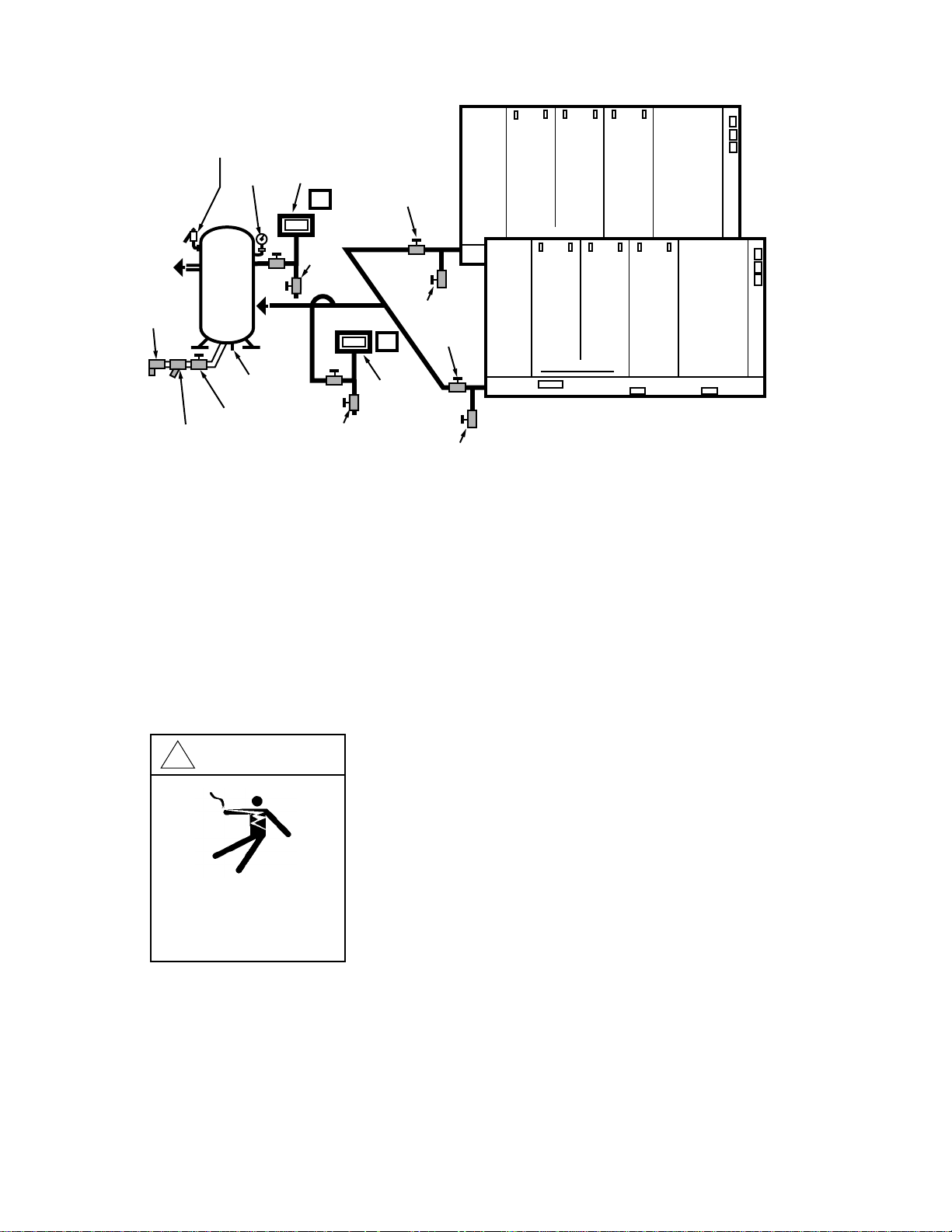
3.2 PRESSURE TRANSDUCER MOUNTING/PIPING
1. Choose one of two typical locations for the transducer.
It can be installed in a receiver tank or in a common discharge air header, as long as either one serves all the
sequenced compressors. See Figure 3.2-2 for Choice A,
the tank; and Choice B, the header.The tank is the recommended location as long as it is close to the compressors.
2. In either location, mount the transducer with a dripleg
and isolation valve to allow for calibration and repairs.
Mount as shown in Figure 3.2-1, and refer to the general
arrangement drawing (Figure 6.10) for mounting dimensions.
3. If the transducer is to be mounted in the air header,
Choice B, connect it to the TOP of the header to prevent
moisture accumulation in the transducer. If the header
runs at floor level, mount the transducer to the wall
above the header and connect it to the top of the header
using pipe or tubing.This will prevent moisture accumulation and damage to the transducer.
NOTE: If there are dryers or filters installed in the system between the compressors and the ISC pressure
transducer, the ISC’s user-set TARGET PRESSURE
must be adjusted to compensate for the pressure drop
caused by these devices.Proper adjustment must be
done to prevent overloading the compressor main drive
motors.This procedure is described in Section 4.2.2
PRESSURE SET UP and CONTROL.
FIGURE 3.2-1 PRESSURE TRANSDUCER
INSTALLATION
6
TO RECEIVER TANK
OR AIR HEADER
DRIP LEG
Page 9
3.3 PRESSURE TRANSDUCER WIRING
Before beginning any work on the ISC, open, lock
and tag the electrical disconnect for the ISC.
1.The transducer cable assembly included in the ISC kit
comes with a preattached transducer connector.Route
the free end of the cable from the transducer to the ISC,
preferably in its own grounded conduit.
2. Connect the cable to the terminal str ip inside the ISC
using the electrical schematic in Figure 6.9 as a reference. Be careful to match color codes and terminal
numbers.
3.4 ISC POWER WIRING
Before beginning any work on the ISC, open, lock
and tag the electrical disconnect for the ISC.
1.The ISC will operate on either a 115 or 230 volts AC,
single phase, 50 or 60 Hz power source.Position the
voltage selection slide on switch SW1, located inside the
ISC at the top left surface of the controller when viewed
from the back, so the number showing on the switch
matches the chosen power source voltage level.
2. Attach the ISC to the power source through an isolation circuit breaker, and protect all wires in conduit.The
ISC draws less than 2 amps.Refer to the electrical
schematic in Figure 6.9.
3. Confir m that all electrical connections are made properly and tightened.
TRAP
FIGURE 3.2-2 ROTARY TWO COMPRESSOR SYSTEM
WITH PRESSURE TRANSDUCERS IN RECEIVER OR HEADER
7
STRAINER
SAFETY
VALVE
PRESSURE
GAUGE
RECEIVER
ISOLATION
VALVE
PRESSURE
DRAIN
TRANSDUCER
A
DRIP
LEG
DRIP
LEG
ISOLATION
VALVE
DRIP
B
PRESSURE
TRANSDUCER
LEG
ISOLATION
VALVE
DRIP
LEG
INGERSOLL-RAND
INGERSOLL-RAND
!
WARNING
Hazardous voltage. Can cause
severe injury or death.
Disconnect power before servicing.
Lockout/Tagout machine.
INGERSOLLrAND ®
Page 10

3.5 ISC COMMUNICATION WIRING
1.The ISC is connected to each compressor using the
telephone type wire supplied in the ISC kit. Cut appropr iate lengths for each compressor and route the wires in
grounded electrical conduit.These wires should be the
only wires in the conduit(s).
2. Install one modular plug (supplied in the kit, along with
a special tool) on each end of each wire, one end in the
compressor and one in the ISC enclosure. Refer to
Figure 6.7 and 6.8 for instructions on the tool, and for
proper wire color codes and pin numbers. Be careful to
match color codes and pin numbers.
3. Plug the compressor end of each wire into the communication port on the compressor’s Intellisys panel or
Intellisys circuit board, whichever is appropriate.
4. Plug the ISC end of each wire into the communication
port on top of the ISC controller that corresponds to the
channel number you choose for each compressor.
Compressors must be connected to ports in consecutive
order, starting with port number 1. For example, if there
are five compressors, they must be plugged into ports 1
through 5, with no unused ports between the first and
the last.
5.Write the compressor model number and capacity,
corresponding to each chosen channel/compressor number, into Figure 6.2 at the back of this manual.
3.6 POWER ON CONFIRMATION
1. After all physical installation and wiring is complete,
apply power to the ISC and confirm the “Power” LED is
on.
If problems are encountered with any part of the ISC
operation, refer to the Trouble Shooting Chart,
Section 5.0.
2.The display will read “INITIALIZING”while the ISC
automatically goes through its internal initialization logic
which checks the pressure transducer and retrieves
compressor status information.
3. Confir m the display reads “READY TO START” following the initializing operation.
4. If necessar y, adjust the display contrast using the
adjustment screw located at the top left surface of the
controller when viewed from the back.
3.7 PRESSURE TRANSDUCER CALIBRATION
This should always be done after first installing the ISC,
or after servicing the ISC or pressure transducer.
1.Vent the transducer to atmospheric pressure by closing the isolation valve and opening the dripleg valve.
2.With the ISC stopped and the display showing
“READY TO STAR T”, press the Up and Down Arrow
keys simultaneously to start the ISC’s autocalibrate routine.The display will show the message “CALIBRATING”
while calibration is taking place.When calibration is successful, the display will return to “READY TO START”.If
calibration is unsuccessful, the display will show “CALI-
BRATION FAIL”. If this occurs, refer to Trouble Shooting
Chart, Section 5.0.
3. Retur n the transducer to system air pressure .
The ISC is now ready for entering the Set Points that
configure it for specific air system requirements.Proceed
to Section 4.2 “Setting Up The ISC”, and follow the
instructions there.
8
Page 11
SEQUENCING
SEQUENCING
UNIT 1
4.0 OPERATION
9
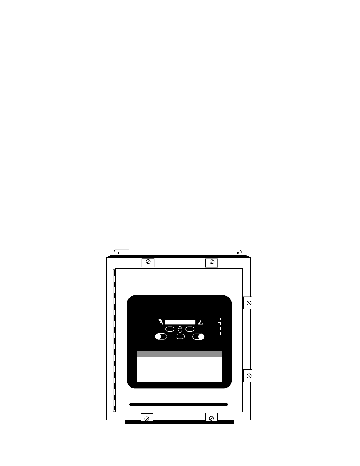
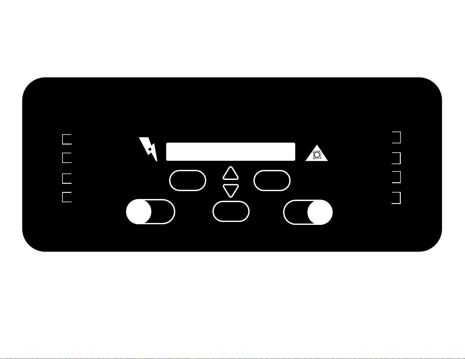
FIGURE 4.0-1 INTELLISYS SYSTEM CONTROLLER PANEL
UNIT 2
UNIT 3
UNIT 4
SEQUENCE •
LOADED •
SEQUENCE •
LOADED •
SEQUENCE •
LOADED •
SEQUENCE •
LOADED •
INGERSOLrAND
INTELLISYS
POWER
SEQUENCER
STATUS
SEQUENCING
START
SET
COMPRESSOR
STATUS
SEQUENCING
SEQUENCING
STOP
• ALARM
• SEQUENCE
• LOADED
• SEQUENCE
• LOADED
• SEQUENCE
• LOADED
• SEQUENCE
• LOADED
UNIT 5
UNIT 6
UNIT 7
UNIT 8
Page 12

4.0 OPERATION
Air system performance can be enhanced by carefully
setting up the Intellisys System Controller (ISC).This
includes selecting operating parameters that customize
the ISC for the specific air system to which it is attached.
This section of the manual first describes the front panel
controls of the ISC, then gives detailed instructions of
how to use these controls to set up and/or adjust the
operating parameters.This is followed with instructions
for Starting and Stopping the ISC, plus how to view ISC
or compressor status information, and finally a description of Alarm conditions.
4.1 OPERATOR PANEL LAYOUT
The ISC panel contains seven buttons, twenty LED (light
emitting diode) lamps and a sixteen character alphanumeric display. The buttons are used for operator input,
the LED’s indicate continuous status infor mation, and the
display provides additional status information during the
setting of Set Points (See Figure 4.0-1).
The following sections outline the functions of each button and the meaning of each LED.The display messages and their use are described in Section 4.2,
“Setting Up The ISC,” where detailed instructions are
provided for each ISC function.
The phrase “Set Point Routine”, used throughout this
manual, refers to the procedures used for observing or
changing the user-selectable variables in the ISC logic.
Figure 6.1 provides a graphical “map”of the Set Points
and how to get to each one.
4.1.1 SEQUENCER START BUTTON
Pressing this button will start the sequencing operation if
pressed while the display shows “READY TO STAR T ”.
The ISC will resume operation in the rotation mode
(Timed, Event or Manual) that was active when the
SEQUENCER STOP button was pressed. However, if
the Set Point routine was used to change to a different
rotation mode while the ISC was stopped, then operation
in that new rotation mode will be started when the button
is pressed.
Pressing this button while in the Sequencer Status or
Compressor Status display modes will return the display
to “READY TO STAR T”if the ISC is not sequencing, but
will display the System Pressure if it is sequencing.
4.1.2 SEQUENCER STOP BUTTON
Pressing this button will stop the sequencing operation if
it is running, as indicated by the “Sequencing” LED being
on. It also retur ns all compressors to their local control.
NOTE: At this time, each compressor might start, stop,
load, or unload itself depending on its own local conditions and set points.
Pressing this button while the ISC is stopped will do a
display test by lighting all the LED’s. This will also cause
the version number of the ISC’s software to be dis-
played.
4.1.3 SEQUENCER STATUS BUTTON
Repeatedly pressing this button will step the display
through the ISC status messages. See Section 4.4 for
details of the messages.
Pressing this button when in the Set Point routine will
exit the routine.
4.1.4 COMPRESSOR STATUS/RIGHT ARROW BUTTON
Repeatedly pressing this button when not in the Set
Point routine will step the display through the individual
compressor status messages. See Section 4.5 for details
of the messages.
When in the Set Point routine, this button is used as a
Right Arrow to step through the five groups of Set Points,
and to move the display cursor to the right. See Section
4.2 for details of these functions.
SEQUENCER
START
SEQUENCER
STOP
SEQUENCER
STATUS
COMPRESSOR
STATUS
10
UNLOADED
STOP
START
SET
SET
Page 13
4.1.5 SET BUTTON
This button has numerous functions in the Set Point routine. It is used to enter the routine, to step through portions of the routine and to “lock in” new set point values.
See appropriate portions of Section 4.2 for details of its
use.
A failure of the ISC’s pressure sensor is one reason for
the “Alarm” LED to light up. Pressing the SET button
when the sensor failure has been corrected will clear the
alarm and turn off the LED. See Section 4.6 for details
concerning all the alarm conditions that could cause the
“Alarm” LED to be on, and when it will go off.
4.1.6 UP AND DOWN ARROW BUTTONS
These are used when in the Set Point routine for changing Set Point values.They are also used in the Rotation
Set Up portion to select among modes.
Pressing both buttons simultaneously will calibrate the
pressure transducer when the display shows “READY T O
START”. See Section 3.7 for details on when and how to
calibrate.
4.1.7 “POWER” LED
This LED lights to indicate there is power applied to the
ISC and that its power supply is working.
4.1.8 “SEQUENCING”LED
This LED lights to indicate the ISC SEQUENCER START
button has been pressed and the ISC is sequencing
compressors.
4.1.9 COMPRESSOR UNIT STATUS LED’s
There is a pair of status LED’s, “ Sequence” and
“Loaded”, for each compressor under the control of the
ISC. Each “Sequence” LED lights to indicate that compressor is in Sequence mode through the communication channel to the ISC. Each “Loaded” LED lights to
indicate that compressor is running loaded.
4.1.10 “ALARM”LED
An alarm status from any of the compressors, a communication failure detected by the ISC or a system pressure
transducer failure detected by the ISC will turn on this
LED. See Section 4.6 for details of each alarm condition
and how each is cleared.
4.2 SETTING UP THE ISC
Setting up, or programming, the ISC is done by entering
chosen values for the ISC operating parameters, which
are called set points. Figure 6.1 is a map of all the ISC
set points and provides a quick reference of how to step
the display to each one.Figures 6.2 through 6.7 list the
set points, show the value limits for each one, and provide space for recording the values chosen for specific
air system requirements.
Before entering any set points, the following set up
instruction sections should be read and used for deciding the exact set point values needed.While reading
these sections and deciding on values, record them in
the ISC Set Up Log, Figures 6.2 through 6.7 (or a copy
of it).Then, using the entries in the log as a guide, execute the steps listed below to enter each set point.
The following guidelines apply when viewing or changing
set point values.
1. Press the SET button to enter the set point routine
while the ISC is operating normally.
2. Press the Right Arrow (COMPRESSOR STATUS) button to step between set point groups, and press the SET
button to step between set points within each group.This
is described in detail in the following sections and is outlined by Figure 6.1.
3. Press Up or Down Arrow buttons to change set point
values.
4. Press the Right Arrow button to select characters within set points, where appropriate.The selected character
will be indicated by an underline cursor in the display.
SET
11
SET
POWER
Page 14

4.2 SETTING UP THE ISC (Continued)
5. Press the SET button to lock in any changed value
and to move to the next set point within a set point
group.If a value has been changed, the display will flash
to acknowledge the change before going to the next set
point.
6. Press the SEQUENCER STATUS button to exit the set
point routine.
7. If no button is pressed within 30 seconds while in the
set point routine, the ISC will automatically exit the routine and return the display to normal operation.
4.2.1 INITIALIZATION
After physical installation is complete, and the “Power On
Confirmation” and “Pressure Transducer Calibration”
steps of Section 3.6 and 3.7 are complete, the ISC is
ready to be configured for specific air system requirements.The following initialization steps must be performed before putting the ISC into operation.There are
default values built in, but each set point must be confirmed or adjusted before starting the ISC. These
should always be checked after first installing the
ISC, or if its controller is ever serviced.
Language
Units of Measure
Number of Compressors
Day and Time Clock
Once the ISC is started by pressing the START button,
the Language, Units of Measure and Number of
Compressors set points can not be accessed until the
ISC is stopped by pressing the STOP button.
All of these items are accessed by entering the Set Point
routine from the “READY TO ST ART” display message.
Perfor m the following steps to access each item, or use
the Set Point Map of Figure 6.1 as a quick reference of
how to get to the INITIAL SET UP Set Points.
Step Action
1 Press the SET button once and observe
“PRESSURE SET UP” in the display.
(Note: If you press SET more than once,
the display will cycle through the Pressure
SET UP Set Points.Setting these will be
described later, in Section 4.2.2.Continue
pressing SET and stop with the display
showing “PRESSURE SET UP”).
2 Press the Right Arrow Button five times,
observe “INITIAL SET UP” in the display,
or continue to press the Right Arrow until
“INITIAL SET UP” appears.
Step Action
3 Press the SET button once, observe the
currently selected language. (This Set Point
will not be accessible while the ISC is run
ning, which is indicated by the “Sequenc
ing” LED being on).
4 Press the Up or Down Arrow button to
cycle the display through the language
choices, stopping on the one you want.
5 Press SET once, observe the currently
selected units of measure.
6 Press the Up or Down Arrow to cycle
through the choices of units of measure,
stopping on the one you want.(This Set
Point will not be accessible while the ISC
is running, which is indicated by the
“Sequencing” LED being on).
7 Press Set once,
observe”________COMPRESSORS”.
8 Press the Up or Down Arrow to enter the
number of compressors that are physically
wired to the ISC and expected to be sequenced.This can be any number from 2
to 8. (This Set Point will not be accessible
while the ISC is running, which is indicated
by the “Sequencing” LED being on).
9 Press SET once, the day and time the ISC
considers to be current will appear,
(Example: “TUE 14:10”). The time is always
shown as a 24 hour clock.For example,
“14:10” is 10 minutes past 2 o’clock
in the afternoon. Press the Right Arrow button (COMPRESSOR STATUS) to position
the display cursor under each of the day or
hours or minutes to set any of them. Once
the cursor is positioned, press the Up or
Down Arrow to set the value you want.
Continue to use the Right Arrow to step
through the items in the display to be
changed, and the Up or Down Arrows to
change them. Set the correct day and time
for your location.
10 Press SET once to lock in the chosen day
and time.
11 Press the SEQUENCER STATUS button to
leave the Set Points and retur n the display
to normal operation.
12
Page 15

4.2.2 PRESSURE SET UP AND CONTROL
The ISC controls the loading and unloading of air compressors for the purpose of maintaining a steady system
air pressure at the point where the pressure transducer
is installed.The Pressure Set Up and Control Set Points
enable the user to choose the desired air pressure and
to adjust three operating parameters that “tune” the ISC
to best maintain that pressure.The Set Points for controlling pressure are:
Pressure Settings (including Target Pressure)
Control Band
Load Delay Time
Unload Delay Time
The Target Pressure in the first Pressure Setting set
point should initially be set to match the pressure present at the transducer location prior to starting the ISC. It
can be adjusted later, after confirming proper air system
operation.With the air system operating in typical fashion, press the SEQUENCER STATUS button to read the
pressure currently at the transducer.Watch the pressure
go up and down, noting the maximum and minimum
readings. Use the pressure value midway between these
readings for the Target Pressure in the first Pressure
Setting.
PRESSURE SET UP
The ISC can store up to nine user selected Pressure
Settings. Each Pressure Setting can be given a Target
Pressure, a day of the week and a time of day.At the
instant a Pressure Setting matches the present day and
time, the ISC will begin loading and unloading compressors based on that Pressure Setting’s Target Pressure.
That Target Pressure will remain active until another
Pressure Setting matches another day and time.
This feature enables the system air pressure to be automatically reduced during non-operating hours to save
energy and automatically returned to the operating level
when needed.
An example of a Pressure Setting Set Point is shown in
Figure 6.4. Using the following rules as guidelines,
decide what Pressure Settings are needed and write
them in Figure 6.4.Then perform the steps that follow
these rules to access the Set Points and to enter the
Pressure Settings.
PRESSURE SETTINGS SET UP RULES:
1. Settings are numbered 1 through 9, and any number
of them can be used.
2. Each Setting is enabled by specifying its Target
Pressure, Day of the Week and Time of Day, or it is disabled by specifying it as “UNUSED” in place of selecting
a Target Pressure.
3.Target Pressure can be set to 0 (zero), any value from
30 to 225 PSI (in 1 PSI increments) or UNUSED. A zero
setting will cause the ISC to unload all machines regardless of the system pressure.
4. Any Day of the Week designator can be assigned to
any number of Settings.Day of the Week can be any
one of the following choices:
MON Monday
TUE Tuesday
WED Wednesday
THU Thursday
FRI Friday
SAT Saturday
SUN Sunday
DLY Daily - every day of the week
WD Week Day - every day Monday thru
Friday
WE Week End - both Saturday and Sunday
(blank) Fixed Target Pressure - This is available
only in Setting Number 1.When “blank”
is used, the Target Pressure of Setting
Number 1 will be used all the time, and
Setting Numbers 2 thru 9 will not be
available.
5. Any Time of Day can be assigned to any number of
Settings. Each Time of Day can be on any hour or quarter of an hour.Time is entered using the 24-hour clock
method. For example, four-thirty in the afternoon would
be entered as 16:30.
6. In case two or more Pressure Settings have the same
Day of the Week and Time of Day entries, the lower
numbered Setting will have priority.
7.When the ISC leaves the Set Point routine, the
Pressure Setting assigned to the current day and time
“period” will be initiated.This is done by the ISC searching through all the Settings to determine which Setting
(i.e.Target Pressure) is supposed to be currently active.
8.This Pressure Settings feature is independent of the
three modes of sequence rotation. It is active regardless
of whether rotation is under Timed, Event or Manual control.
Perfor m the following steps to enter or change Pressure
Settings, or use the Set Point Map (Figure 6.1) as a
quick reference of how to get to the PRESSURE SET
UP Set Points.
13
Page 16

Step Action
1 While not in any Set Point routine, press the
SET button once and observe
“PRESSURE SET UP” in the display.
2 Press SET once, observe something like
“1 100 DLY 6:45”.
(This is the place to enter the first Pressure
Setting.This example says the first Setting
(1) will operate the ISC at a Target Pressure
of 100 PSI (100) beginning every day of the
week (DLY) at forty-five minutes past six
o’clock in the morning (6:45). If this is the
only Setting being used, the display will not
show any day nor time designators.)
3 Press the Up or Down Arrow buttons to set
the system air pressure that the ISC is to
maintain. If a Setting is to be unused, press
the Arrow buttons until “PRESS#________
UNUSED” appears in the display.
(The display shows a cursor under the
charactor position that the arrow buttons will
affect).
4 Press the Right Arrow button to position the
cursor under the Day or Time to be entered.
5 Press the Up or Down Arrow button to cycle
the item to the desired value.
6 If there are more items to be entered in this
particular Setting, repeat steps 4 and 5
above.When there are no more items to be
entered, press the SET button to lock in the
Setting values and to step to the next
Setting.
7 Repeat steps 3 through 6 to program all
desired Settings.
8 When all Settings are entered and confirmed
correct, press the SET button to step
through any remaining settings until the
display returns to “PRESSURE SET UP”.
9 Press the SEQUENCER STATUS button to
leave the Set Points and retur n the display
to normal operation.This will cause the ISC
to immediately search through all Pressure
Settings to determine which one (i.e.Target
Pressure) is to be currently active.
PRESSURE CONTROL
The ISC will maintain the Target Pressure by loading
compressors when the pressure is below the “lower
pressure limit”, which is defined as the Target Pressure
minus one-half of the Control Band. Likewise, the ISC
will unload compressors when the pressure is above the
“upper pressure limit”, which is the Target Pressure plus
one-half of the Control Band. For example, if the Target
Pressure is set at 100 PSI and the Control Band is set at
8 PSI, the ISC will make decisions concerning loading
compressors when the system pressure drops to 96 PSI.
In the same manner, it will make decisions concerning
unloading compressors when the system pressure rises
to 104 PSI.
When the system pressure falls below the “lower pres-
sure limit”, the last compressor to have been unloaded is
immediately told to load.The Load Delay Time is the
length of time the ISC then waits before telling the next
compressor to load.
Explanation: Once a compressor is signaled to load,
the Load Delay Timer is reset and restarted. This
process will continue until the pressure begins to rise. As
long as the pressure is rising, no more compressors will
be told to load. If the pressure stops r ising but is still
below the “lower pressure limit”, the Load Delay Timer
will be reset and restarted in anticipation of telling another compressor to load.The Load Delay Timer has no
effect when the system pressure is above the “lower
pressure limit”.
When the system pressure rises above the “upper pressure limit”, the last compressor to have been loaded is
immediately told to unload.The Unload Delay Time is the
length of time the ISC then waits before telling the next
compressor to unload, if the pressure is still above the
“upper pressure limit”.
Explanation: After a compressor is signaled to unload,
the Unload Delay Timer is reset and restarted, and the
process continues until the pressure begins to drop.If
the pressure stops going down but remains above the
“upper pressure limit”, the timer and unloading process
will resume.The Unload Delay Timer has no effect when
the system pressure is below the “upper pressure limit”.
14
Page 17

If the system pressure should ever rise above the “maxi-
mum pressure limit”, which is defined as 5 PSI above the
“upper pressure limit”, the ISC will tell all compressors to
unload at once. If the pressure then drops to the “upper
pressure limit” within one minute, the ISC will tell all previously loaded compressors, except the last one, to load
again. If however, it takes the pressure more than one
minute to drop to the “upper pressure limit”, the ISC will
tell only the first compressor in the sequence to load. In
either case, since the pressure will be within the Control
Band, the normal sequence logic will apply.
The Pressure Control Set Points can be accessed by
entering the Set Point routine while ISC is either stopped
or running. Perfor m the following steps to access each
item, or use the Set Point Map of Figure 6.1 as a quick
reference of how to get to the PRESSURE CONTROL
Set Points.
Step Action
1 While not in any Set Point routine, press the
SET button once and observe “PRESSURE
SET UP” in the display.
(NOTE: If you press SET more than once, the
display will cycle through the Pressure Set Up
Set Points.Continue Pressing SET
and stop with the display showing
“PRESSURE SET UP”).
2 Press the Right Arrow button once, observe
“PRESSURE CONTROL” in the display, or
continue to press the Right Arrow button until
you do see it.
3 Press SET once, observe “CONTROL
BAND___________.”
4 Press the Up or Down Arrows to set the width
of the pressure band the ISC is to use for
loading and unloading compressors.The
width is always even, with half of it above the
Target Pressure and half below the Target
Pressure.
(Note: See the beginning of this section for an explanation of the Control Band, the Load Delay Time, and the
Unload Delay Time.)
5 Press SET once, observe “WAIT LOAD______
SEC”.
6 With the display showing “WAIT
LOAD _____SEC”, press the UP or Down
Arrow buttons to set the Load Delay Time in
seconds.
Step Action
7 Press SET once, observe
“UNLOAD _______SEC”.
8 With the display showing
“UNLOAD_______SEC”, press the Up or Down
Arrow buttons to set the Unload Delay Time
in seconds.
9 Press SET to step through each of the
PRESSURE CONTROL Set Points and
confirm that each is correct, or change any
as necessary.
10 Press the SEQUENCER STATUS button to
leave the Set Points and retur n the display
to normal operation.
4.2.3 SEQUENCE SET UP
The ISC can store up to eight user selected sequences,
called sequence “A” through sequence “H”, plus a ninth
called sequence “M”, which is used only when in Manual
mode. A sequence is a specified numerical order of
compressors which the ISC will follow when loading and
unloading compressors to maintain the system air pressure at the preset Target Pressure. Each compressor’s
number corresponds to the communication channel
number it is plugged into inside the ISC enclosure. See
INSTALLATION Section 3.0 for details, and refer to the
“Compressor Control” setpoints (Figure 6.2) that was
completed as part of the installation procedure.
The same eight sequences, “A” through “H” are used by
both the Timed and the Event modes of rotating from
one sequence to the next. See Section 4.2.5, Sequence
Rotation Mode, for setting up the modes.It is important
to know that the Timed mode always rotates from one
sequence to the next in “alphabetical order”.This means
that when Timed mode is started, sequence “A” will
always run first, followed by “B”after the Elapsed Run
Time expires, followed by “C”, etc.
Timed mode rotation will loop from the last sequence
entered back to “A” and continue indefinitely.
Using the following rules, decide what sequences the
ISC is to use and write them in the appropriate section
of Figure 6.6.Then perform the steps that follow these
rules to enter the chosen sequences into the ISC.
15
Page 18

SEQUENCE SET UP RULES:
1. Compressors are numbered 1 through 8 with no gaps in
the numbering. For example, if there are five compressors,
they must be connected to communication channels 1
through 5.
2. Sequences lettered A through H are used for both
Timed and Event modes.Sequence M is used only by the
Manual mode, and its set up is described in the Manual
mode portion of Section 4.2.5.
3. Any number of the eight sequences can be used. All of
them do not need to be entered.
4. Compressors can be entered in any sequence, in any
order.
5.The first compressor (number) entered in any sequence
will be the first one to load when air is needed. It is commonly refered to as the “lead”compressor.Loading of the
other compressors will follow in the order in which they are
entered in the sequence, from left to right.
6.The same compressor number can not be entered into a
given sequence more than once.
7. No compressor number larger than the quantity of compressors entered in the Initial Set Up can be entered in
any sequence.
8. Leaving the first character position in any sequence
“blank” will indicate that sequence is not used.
Perfor m the following steps to enter or change sequences,
or use the Set Point Map (Figure 6.1) as a quick reference
of how to get to the SEQUENCE SET UP Set Points.
Step Action
1 While not in any Set Point routine, press
the SET button once and observe
“PRESSURE SET UP” in the display.
(NOTE: If you press SET more than once,
the display will cycle through the Pressure
Set Up Set Points.Continue pressing SET
and stop with the display showing
“PRESSURE SET UP”).
2 Press the Right Arrow button twice, observe
“SEQUENCE SET UP” in the display, or
continue to press the Right Arrow button
until you do see it.
3 Press SET once, observe something like
“SEQ A 213”.
(This is the place to enter the first se-
quence, “A”.This example shows sequence “A” with compressor number 2 as
the “lead” compressor (first to load) followed by compressor 1 followed by compressor 3.The display shows a cursor
under the compressor position that the ar
row buttons will affect.In the example, the
cursor position would be under 2).
4 Press the Up or Down Arrow button to cy-
cle the number to the compressor to be put
in the first position in the sequence.
(NOTE:When a position’s compressor
number is changed, all compressor
numbers to the right will go blank).
5 Press the Right Arrow button once to step
the display cursor to the next compressor
number position to be entered.
6 Press the Up or Down Arrow button to cy-
cle the number to the compressor to be put
in this position in the sequence.
7 If there are more compressor numbers to
be entered in this sequence, repeat steps 5
and 6 above.
When there are no more compressor
positions to be entered in this sequence,
press the SET button to lock in the sequence,
and to step to the next sequence.
8 Repeat steps 4 through 7 to program all
desired sequences.
9 When all sequences are entered and con-
firmed correct, press the SEQUENCER
STATUS button to leave the Set Points and
return the display to normal operation.
16
Page 19

4.2.4 COMPRESSOR CONTROL
Each compressor can be set to Local or Sequence control through the ISC. Local control means the ISC will
bypass that particular compressor in all sequences, and
will not tell it to load or unload. Sequence control means
the ISC will include the compressor in any sequence that
calls for it.
The Compressor Control Set Points can be accessed by
entering the Set Point routine while the ISC is either
stopped or running. Perfor m the following steps to
access each compressor, or use the Set Point Map of
Figure 6.1 as a quick reference of how to get to the
COMPRESSOR CONTROL Set Points.
Step Action
1 While not in any Set Point routine, press
the SET button once and observe
“PRESSURE SET UP” in the display.
(NOTE: If you press SET more than once,
the display will cycle through the Pressure
Set Up Set Points.Continue pressing SET
and stop with the display showing
“PRESSURE SET UP”).
2 Press the Right Arrow button three times,
observe “COMP CONTROL” in the display,
or continue to press the Right Arrow button
until you do see it.
3 Press SET once, observe something like
“#1 LOCAL”, This would indicate that
compressor 1 is under its own (local)
control.
4 Press the Up or Down Arrow button to
toggle the compressor between LOCAL or SEQUENCE CONTROL, leaving the display at
the selected mode.
5 Press SET once to lock in the selected
mode for that compressor and to step to
the next compressor.
6 If there are more compressors to have their
control mode set, repeat steps 4 and 5
above.When the control of all compressors
has been set and confirmed correct, press
the SEQUENCER STATUS button to leave
the Set Points and return the display to
normal operation.
4.2.5 SEQUENCE ROTATION MODES
One sequence of compressors can be replaced by
another sequence through a process called “rotation”.
Rotating from one sequence to another can be initiated
automatically by the ISC or manually by the operator.
Automatic rotation occurs when the ISC is put in either
TIMED Mode or EVENT Mode. Manual rotation occurs
when the operator puts the ISC in MANUAL Mode.
The ROTATION SET UP Set Points can be accessed by
entering the Set Point routine while the ISC is either
stopped or running. All the Set Points for all three modes
can be entered, but the last mode selected is the one
that will begin to operate immediately upon exiting the
Set Point routine.While TIMED and EVENT modes are
two different ways to automatically rotate sequences,
they both use the same eight sequences, A through H.
(See Section 4.2.3 for set up of the sequences).The following sections detail how to select and enter the Set
Points for each mode, but only the Set Points for the
mode intended to be used need to be entered.
The Set Point Map (Figure 6.1) can be used as a quick
reference of how to get to the ROTATION SET UP Set
Points.Also, it is recommended that the ISC Set Up Log,
“Sequence Rotation Mode” Set Points, (Figure 6.7) be
used for writing down the desired Set Points before
entering them into the ISC.The Log is then available to
serve as a reference for checking what Set Points have
been entered.
TIMED ROTATION MODE
In TIMED rotation mode, the ISC rotates from the currently running sequence to the next one every time the
accumulated compressor running hours during the current sequence equals the “Elapsed Run Time” hours set
point. “Compressor running hours” is defined as the time
accumulated when at least one compressor on the ISC
is running and when the ISC is in TIMED mode.
The order of rotation is always sequence A followed by
B, then C, etc.to the last sequence entered, then back
to A.This means that when the TIMED mode is selected
after making any change to any sequence, the ISC will
restart sequencing with sequence A and will reset the
accumulated compressor running hours to zero.On the
other hand, if TIMED mode was active, then replaced by
another mode, then reactivated with no changes having
been made to any sequences, ISC operation will resume
in the same sequence (rotating to it if necessary) and
with the same accumulated compressor running hours
that were present when TIMED mode was exited.
The only set up required that is unique to the TIMED
rotation mode is the entering of the Elapsed Run Time
Set Point.Perform the following steps to enter or change
the Elapsed Run Time, or use the Set Point Map (Figure
6-1) as a quick reference of how to get to the TIMED
rotation mode and the Set Points.
17
Page 20

Step Action
1 While not in any Set Point routine, press
the SET button once and observe
“PRESSURE SET UP” in the display.
(NOTE: If you press SET more than once,
the display will cycle through the Pressure
Set Up Set Points.Continue pressing SET
and stop with the display showing
“PRESSURE SET UP”).
2 Press the Right Arrow button four times,
observe “ROTATION SET UP” in the
display or continue to press the Right Arrow
button until you do see it.
3 Press SET once and observe the presently
active Rotation Mode showing in the
display.
4 If necessary, press the Up or Down Arrow
button one or two times until
“MODE:TIMED” is displayed.
(NOTE:The mode that was active when the
set point routine was entered will remain
active even when accessing other modes
and their set points.The mode that the ISC
is running will change only upon exiting the
set point routine).
5 Press SET once, observe “SEQ CHG______
HRS”.
(NOTE:The display will flash twice in-
dicating the TIMED Mode has been
selected if some other mode had previously
been active).
6 Press the Up or Down Arrow buttons to set
the compressor running hours the ISC is to
accumulate before rotating to the next
sequence.
7 Press SET once to lock in the selected
hours and to return to “ROTATION SET
UP”.
8 Press the SEQUENCER STATUS button to
leave the Set Points and retur n the display
to normal operation.This will cause the
TIMED mode to immediately become active.
EVENT ROTATION MODE
In the EVENT rotation mode, the ISC rotates from the
currently running sequence to the sequence specified to
be active at the moment an Event matches the present
day and time.An Event is defined as a user set day of
the week and a user set time of that day.There can be
as many as nine Events entered through the Set Point
routine. Each Event can be preset to start a selected
sequence on a selected day of the week at a selected
time of day. That sequence will remain active until
another Event occurs.
An example of an Event Set Point is shown in the ISC
Set Up Log (Figure 6.7). Using the following rules as
guidelines, decide what Events are needed and write
them in the ISC Set Up Log (Figure 6.7) Then perfor m
the steps that follow these rules to access the Set Points
and to enter the Events.
EVENT SET UP RULES:
1. Events are numbered 1 through 9, and any number of
them can be used.
2. Each event is enabled by specifying its Sequence,
Day of the Week and Time of Day, or it is disabled by
specifying it as “UNUSED” in place of selecting a
Sequence.
3. Any of the sequences, A through H, can be assigned
to any number of Events.However, a sequence must first
be programmed through the SEQUENCE SET UP Set
Points before it can be assigned to an Event (See
Section 4.2.3 for Sequence Set Up).
4. Any Day of the Week designator can be assigned to
any number of Events.Day of the Week can be any one
of the following choices:
MON Monday
TUE Tuesday
WED Wednesday
THU Thursday
FRI Friday
SAT Saturday
SUN Sunday
DLY Daily - every day of the week
WD Week Day - every day Monday thru Fr iday
WE Week End - both Saturday and Sunday
5. Any Time of Day can be assigned to any number of
Events.Each Time of Day can be on any hour or quarter
of an hour.Time is entered using the 24-hour clock
method. For example, four-thirty in the afternoon would
be entered as 16:30.
18
Page 21

6. In case two or more Events have the same Day of the
Week and Time of Day entries, the lower numbered Event
will have priority.
7.When Event Mode is selected to be active, the
sequence assigned to the current day and time “period”
will be initiated.This is done by the ISC searching through
all the Events to determine which Event (and sequence) is
supposed to be currently active and rotating to it.
8. Remember to adjust the Day and Time Clock when
appropriate for Daylight Savings Time.
Perfor m the following steps to enter or change Events, or
use the Set Point Map (Figure 6.1) as a quick reference of
how to get to the EVENT rotation mode Set Points.
Step Action
1 While not in any Set Point routine, press
the SET button once and observe
“PRESSURE SET UP” in the display.
(NOTE: If you press SET more than once,
the display will cycle through the Pressure
Set Up Set Points.Continue pressing SET
and stop with the display showing
“PRESSURE SET UP”).
2 Press the Right Arrow button four times,
observe “ROTATION SET UP” in the
display, or continue to press the Right
Arrow button until you do see it.
3 Press SET once and observe the presently
active Rotation Mode showing in the
display.
4 If necessary, press the Up or Down Arrow
button one or two times until “MODE:
EVENT” is displayed.
(Note that the mode that was active when
the set point routine was entered will remain active even when accessing other
modes and their set points.The mode that
the ISC is running will change only upon
exiting the set point routine).
Step Action
5 Press SET once, observe something like
“1 A MON 6:45”.
(NOTE:The display will flash twice in-
dicating the EVENT Mode has been
selected if some other mode has previously
been active.)
(This is the place to enter the first Event.
This example says the first Event (1) will
start sequence A (A) every Monday (MON)
morning at forty-five minutes past six
o’clock (6:45). If this Event has previously
been unused, the display will say “EVENT
#1 UNUSED”).
6 Press the Up Arrow button to cycle the se-
quence letter to the one intended for this
Event or to “UNUSED”.
(The display shows a cursor under the
character position that the arrow buttons
will affect).
7 Press the Right Arrow button to position the
cursor under the Day or Time item to be
entered.
8 Press the Up or Down Arrow button to cy-
cle the item to the desired value.
9 If there are more items to be entered in this
particular Event, repeat steps 7 and 8
above.When there are no more items to be
entered for this Event, press the SET button to lock in the Event values and to step
to the next Event.
10 Repeat steps 6 through 9 to program all
desired Events.
11 When all Events are entered and confirmed
correct, press the SET button to step
through any remaining Events until the
display returns to “ROTATION SET UP”.
12 Press the SEQUENCER STATUS button to
leave the Set Points and retur n the display
to normal operation.This will cause the
EVENT mode to immediately become
active.
19
Page 22

MANUAL ROTATION MODE
In the MANUAL Rotation Mode, the ISC rotates from whatever sequence is currently running, regardless of the current rotation mode, directly to the sequence designated M
that is set up in the Manual mode Set Point.This occurs
immediately upon exiting the Set Point routine after selecting MANUAL Mode.
The only set up required for the MANUAL Mode is the
entering of Sequence M itself. Perform the following steps
to enter or change Sequence M, or use the Set Point Map
of Figure 6.1 as a quick reference of how to get to the
MANUAL rotation mode Set Point.
Step Action
1 While not in any Set Point routine, press
the SET button once and observe
“PRESSURE SET UP” in the display.
(NOTE: If you press SET more than once,
the display will cycle through the Pressure
Set Up Set Points.Continue pressing SET
and stop with the display showing
“PRESSURE SET UP”).
2 Press the Right Arrow button four times,
observe “ROTATION SET UP” in the
display or continue to press the Right Arrow
button until you see it.
3 Press SET once and observe the presently
active Rotation Mode showing in the
display.
4 If necessary, press the Up or Down Arrow
button one or two times until “MODE:
MANUAL” is displayed.
(Note that the mode that was active when
the set point routine was entered will remain active even when accessing other
modes and their set points.The mode that
the ISC is running will change only upon
exiting the set point routine).
5 Press SET once, observe something like
“SEQ M 4123”.
(NOTE:The display will flash twice in-
dicating the MANUAL Mode has been
selected if some other mode had previously
been active).
(This display shows whatever was last
entered as Sequence M).
Step Action
6 Press the Right Arrow button to step the
display cursor to the compressor number
position to be entered.
(In the example, the first position would be
under the 4).
7 Press the Up or Down Arrow button to cy-
cle the number to the compressor to be put
in this position in the sequence.
8 If there are more compressor numbers to
be entered, repeat steps 6 and 7 above.
If there are no more compressor positions
to be entered in the Manual sequence,
press the SET button to lock in this sequence and to return to “ROTATION SET
UP”.
9 Press the SEQUENCER STATUS button to
leave the Set Points and retur n the display
to normal operation.This will cause the
MANUAL mode to immediately become active, and the ISC will rotate directly to
Manual sequence M.
20
Page 23

4.3 STARTING AND STOPPING
There are general rules to keep in mind when starting an
air system controlled by an ISC.However, there is not
one, strict way that it has to be done.Observe the following rules to ensure a smooth start up.
1. Compressors can be either star ted or stopped when
the ISC is started.
2. Each compressor must be star ted at its own control
panel and placed in a mode able to load before the ISC
can take control, If a compressor is stopped locally, it
must be started locally again. The following list outlines
what to do for each of five types of Ingersoll-Rand
Intellisys compressors to enable them to give control to
the ISC. It is recommended that all compressors have
the auto start/stop feature installed for maximum energy
savings.
5-10 Install an ISC Interface II Kit.
Start the compressor (it auto loads).
SE Models Turn the sequence option set point
“ON”.
Start the compressor (it auto loads).
U-Series Start the compressor.
Press the LOAD button.
SSR/Sierra Turn the sequence option set point
“ON”.
Start the compressor.
Press the ON-LINE/OFF-LINE button.
Recip Turn the sequence option set point
“ON”.
Start the compressor.
Press the CONSTANT SPEED
CONTROL or AUTO/DUAL button.
3. After all installation and set up instr uctions have been
completed as described earlier in this manual and the
display shows “READY TO STAR T”, the ISC is started by
pressing the SEQUENCER START button.
4. Based on the current pressure reading and the Target
Pressure set point, the ISC will load compressors in the
order specified by the current sequence.Any compressor not properly started and enabled for sequencing will
be skipped in the sequence. Each compressor’s status
can be observed on the ISC, refer to Section 4.5.If a
compressor is enabled after the ISC is started, it will be
included in the sequence in its appropriate position when
demand for air warrants it.
5.The ISC leaves the auto start/stop function to the individual compressors.The ISC will not stop machines. A
compressor will stop itself if it meets its own set point criteria for doing an auto stop.It will then restart when it
receives a load command from the ISC.
The ISC is stopped by pressing the SEQUENCER STOP
button.This stops all sequencing of compressors, but
compressor status is still available. Load and unload
control of the compressors is returned to their respective
local controllers. As long as the Rotation Mode set points
are not changed, pressing the SEQUENCER START
button will restart the ISC operation in the same mode it
was in when stopped.
NOTE: When the ISC is stopped, each compressor
might start, stop, load or unload itself depending on its
own local conditions and set points. For example, if the
ISC is stopped while it is operating the system at a pressure lower than a compressor’s on-line setting, and the
compressor is stopped by its Auto Restart, the compressor might immediately start.
4.4 ISC STATUS
Repeatedly pressing the SEQUENCER STATUS button
will step the display through the following ISC status
messages.
System Pressure
Current Sequence
Mode of Operation or Time to Next Rotation
Target Pressure
Clock
System Pressure is the air pressure currently being
measured by the ISC pressure transducer. This is the
normal, or default, display message after the ISC is
started. The display will automatically return to this message if no button is pressed in 30 seconds.
Current Sequence is the sequence of compressors currently being followed by the ISC, showing the compressor numbers in order from left to right.
Mode of operation is “EVENT MODE” if the ISC is currently operating in Event Rotation Mode or “MANUAL
MODE” if currently in Manual Rotation Mode. If the ISC
is currently in Timed Rotation Mode, the display will be
“SEQ CHG 125 HRS” showing how many hours (example is 125) until the ISC rotates to the next sequence.If
the remaining time is less than two hours, it will show the
time in minutes.
Target Pressure is the air pressure in the Pressure
Setting that the ISC is currently using for managing the
air system.
Clock is the current day of the week and the current time
expressed in 24-hour format.
21
Page 24

4.5 COMPRESSOR STATUS
As described in Section 4.1.9 there is a pair of front
panel status LED’s “Sequence” and “Loaded”, for each
compressor under the control of the ISC. Each
“Sequence” LED lights to indicate that compressor is in
Sequence mode through the communication channel to
the ISC. Each “Loaded” Led lights to indicate that compressor is running loaded.
In addition, there are more detailed status messages
available through the display.Repeatedly pressing the
COMPRESSOR STATUS button will step the display
through each compressor number (#1 through the number of compressors entered during initial set up), accompanied by a message indicating that compressor’s sta-
tus.There are seven different status messages that can
be displayed for each compressor.The messages and
their meanings are as follows:
“#1 LOCAL” Compressor number 1 is not under
sequence control.
“#1 RUNNING Compressor number 1 is not under
LOCAL” sequence control and is running.
“#1 STOPPED” Compressor number 1 is under
sequence control and is stopped in its
auto restart mode.
“#1 RUNNING” Compressor number 1 is under
sequence control and is running.
“#1 WARNING” Compressor number 1 is in a “WARN-
ING” state defined by its own controller.
“#1 ALARM” Compressor number 1 has stopped
itself in an “Alarm” state defined by
its own controller.
“#1 COMM Compressor number 1 com-
FAILURE” munication channel has persistent
serial communication problems from
which the ISC is unable to
automatically recover.
4.6 ALARMS
The “Alarm” LED on the ISC’s front panel will light for
any one of the following three reasons.
1. Any time the ISC receives an Alarm status message
from any compressor, it turns on the “Alarm” LED and
provides the Alarm message for that particular compressor as described in Section 4.5 . When the compressor’s
Alarm condition is cleared at the machine, the ISC automatically turns off the “Alarm” LED and changes that
compressor’s status message accordingly.
2. Any time the ISC detects a failure to communicate
with a compressor, it turns on the “Alarm” LED and provides the Communication Failure message for that particular compressor as described in Section 4.5. When
communication is reestablished with the compressor, the
ISC automatically turns off the “Alarm” LED and changes
that compressor’s status message accordingly.
3. If the ISC deter mines it is no longer receiving valid
readings from its pressure transducer, it turns on the
“Alarm” LED, displays “SENSOR FAILURE” and stops all
sequencing, allowing the compressors to return to their
local controls.The ISC will stay in this state until the sensor problem is corrected and the alarm is manually
cleared through the front panel.The alarm state is
cleared by pressing the SET button.To resume sequencing, the ISC must be started by pressing the
SEQUENCER START button.This is the only alarm that
will not automatically clear when the problem is corrected.
The “Volt-free Alar m Contacts” on connector J1 ter minals
4, 5 and 6 will activate for any compressor Alarm or for
an ISC sensor failure.The contacts reset to normal condition when the Alarm is cleared per the above Alarm
LED descriptions.
The ISC software versions for which the Alarm LED and
the Alarm Contacts are active are summarized in the following table:
ISC Software Alarm LED Alarm Contacts
v1.0/v1.1/v1.2 Activated Activated
Any Compressor Alarm v1.0, v1.1, v1.2 v1.2
Communication Failure v1.0, v1.1, v1.2 None
ISC Sensor Failure v1.0, v1.1, v1.2 v1.0, v1.1, v1.2
22
Page 25

5.0 ISC TROUBLE SHOOTING CHART
TROUBLE CAUSE AND/OR DISPLAY WHAT TO DO
ISC POWER light is off. No message in display, no lights on. 1. Check fuse and wiring connections.
2. Check power source disconnect box.
Bad system air pressure readings. “SENSOR FAILURE” 1. Check for defective ISC air system
pressure transducer, bad connections
or broken wires.
Zero pressure reading when pressure 1. Check air system pressure transducer
is present. isolation valves to ensure system air
is getting to the transducer.
Can’t calibrate air system “CALIBRATION FAIL” 1. Check transducer isolation
pressure transducer. valves to ensure the transducer is vented
to atmosphere.
2. Check for defective ISC air system pressure transducer, bad connections or
broken wires.
Any compressor’s (#n) “#n COMM FAILURE” 1.Check compressor to ensure power
communication problem. is on and compressor controller is
operating.
2. Check all communication channel wiring
between the ISC and the compressor.
ISC ALARM light is on Nor mal display 1. Check status of each compressor
using the COMPRESSOR STATUS button.
Find which compressor is showing “#n
COMM FAILURE” or “#n ALARM”. If
showing “#n COMM FAILURE”, see above.
If showing “#n ALARM”, go to that compressor and resolve its Alarm.
“SENSOR FAILURE” 1. See “SENSOR FAILURE” above.
23
Page 26

6.0 REFERENCE DRAWINGS
24
6.1 ISC SET POINT MAP
Page 27
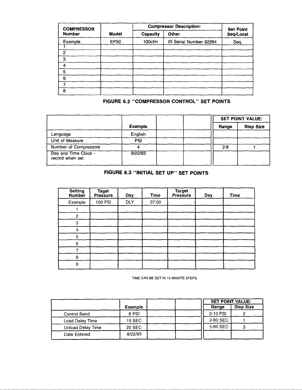
6.5 “PRESSURE CONTROL” SET POINTS
6.4 “PRESSURE SETTINGS”SET POINTS
25
Page 28

FIGURE 6.7 “SEQUENCE ROTATION MODE”SET POINTS
FIGURE 6.6 “SEQUENCE SET UP ” SET POINTS
26
Page 29

The following are instructions to attach 6 position modular plugs to communication cable.
1.Trim cable end flush.
2. Str ip off 1/4” of cable jacket from wires.
3. Cut off the blue with white stripe and the white with
blue stripe wires.
4. Inser t wires as shown below and in Figure 6.9 in connector until wires fully bottom. Be sure to maintain proper conductor polarity by following the color codes and pin
numbers.
5. Inser t modular plug connector - TAB UP - into die set.
LOCKING TAB MUST SNAP INTO CAVITY.
6. Squeeze tool handles together until movable anvil is
completely bottomed.Two “clicks” or 11 snaps” should be
heard or felt.
7. Allow tool handles to open fully, depress locking tab
on connector and remove terminated connector.
FIGURE 6.9 MODULAR PLUG CONNECTIONS
FIGURE 6.8 INSTALLING MODULAR PLUG CONNECTOR
27
Page 30

39844345
REV 04
FIGURE 6.10 ELECTRICAL SCHEMATIC
28
Page 31
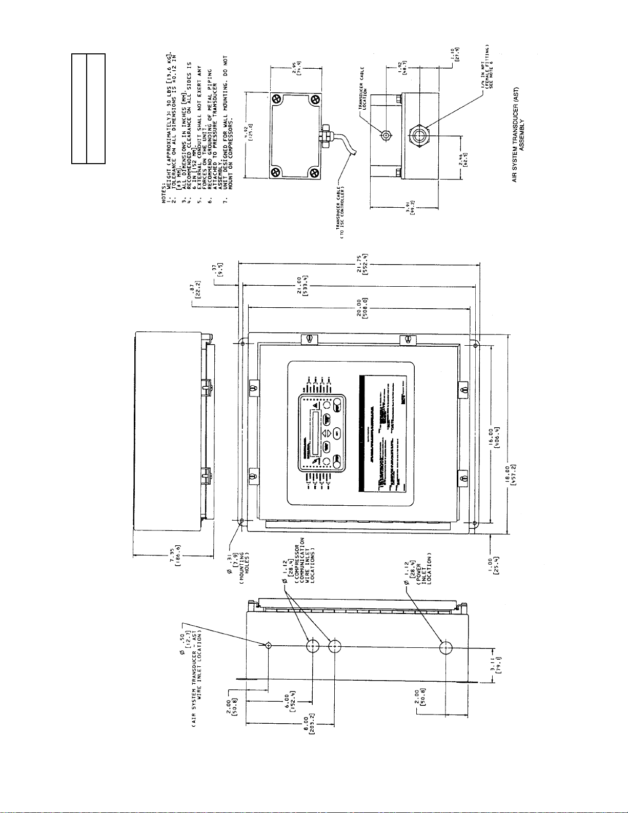
39842224
REV 01
FIGURE 6.11 GENERAL ARRANGEMENT
29
Page 32

NGERSOLrAND
INTELLISYS
ALARM
SEQUENCE
LOADED
SEQUENCE
LOADED
SEQUENCE
LOADED
SEQUENCE
LOADED
POWER
SEQUENCING
START
SET
SEQUENCER
STATUS
COMPRESSOR
STATUS
SEQUENCING
SEQUENCING
STOP
SEQUENCE
LOADED
SEQUENCE
LOADED
SEQUENCE
LOADED
SEQUENCE
LOADED
FIGURE 6.12 TYPICAL ISC INSTALLATION
GROUND CONDUIT
WITH COMMUNICATION
WIRES GOING TO
COMPRESSOR BEING
SEQUENCED
AIR SYSTEM
TRANSDUCER CABLE
LOCKABLE
ELECTRICAL
DISCONNECT
INCOMING
POWER
INTELLISYS SYSTEM CONTROLLER
30
INGERSOLrAND
INTELLISYS
•
SEQUENCE
UNIT 1
LOADED
•
SEQUENCE
•
UNIT 2
UNIT 3
UNIT 4
POWER
LOADED
•
SEQUENCE
•
LOADED
•
SEQUENCE
•
LOADED
•
SEQUENCING
START
SEQUENCER
STATUS
•
ALARM
•
SEQUENCE
UNIT 5
•
LOADED
•
SEQUENCE
UNIT 6
•
LOADED
SEQUENCING
•
SEQUENCE
COMPRESSOR
STATUS
SEQUENCING
SET
STOP
UNIT 7
•
LOADED
•
SEQUENCE
UNIT 8
•
LOADED
D
NOTICE
INGERSOLL-RAND®
Page 33

FIGURE 6.13 TYPICAL AIR SYSTEM
39844105
REV 01
31
Page 34

7.0 PARTS LIST
39839253
REV 03
32
Page 35
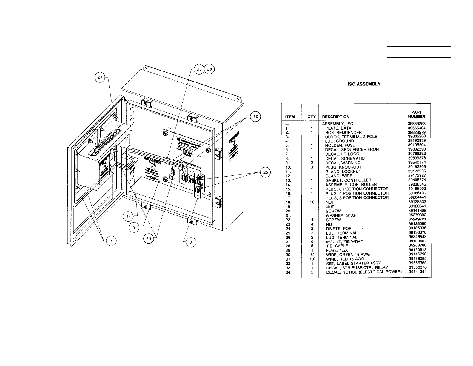
39839253
REV 03
33
Page 36

39841838
REV 02
34
Page 37

PRESSURE TRANSDUCER ASSEMBL Y
ITEM PART
NO. NUMBER QTY. DESCRIPTION
1. 39841630 1 ENCLOSURE
2. 39566500 1 TRANSDUCER,PRESSURE
3. 39153861 1 BUSHING
4. 50677459 1 BULKHEAD ASSY. (3 PARTS)
5. 39131859 1 O-RING
6. 42368530 1 CABLE ASSEMBLY
7. 39173935 1 LOCKNUT
8. 39173927 1 GLAND
35
Page 38

ISC KIT (PART NO. 42367813)
PART
NUMBER OTY. DESCRIPTION
39839253 1 ISC ASSEMBLY
39841838 1 ISC PRESSURE TRANSDUCER ASSEMBLY (225 PSI)
39204508 1 CABLE, COMMUNICATION (1000 FEET)
39204466 18 PLUG, MODULAR
39204458 1 TOOL, HAND CRIMPING
APDD 565B 1 ISC OPERATORS MANUAL
36
Page 39

DATE RUN TIME WORK DONE QTY. UNIT WORK
(HOURS) MEASURE BY
8.0 MAINTENANCE RECORD
37
Page 40

DATE RUN TIME WORK DONE QTY. UNIT WORK
(HOURS) MEASURE BY
MAINTENANCE RECORD
38
Page 41

Page 42

 Loading...