

Ingersoll-Rand Intellisys SSR 10-40, Intellisys SSR 50-450 Serviceman's Manual
IntellisysTM Serviceman's Guide
SSR® 10 - 40 Horsepower Models
SSR 50 - 450 Horsepower Models

INDEX
PAGE
INTRODUCTION ..........................................................................................1
COMPONENTS............................................................................................1
SENSORS ....................................................................................................4
OPERATION.................................................................................................4
INDICATOR LIGHTS ....................................................................................6
MESSAGES..................................................................................................6
MESSAGE -01- STARTER FAILURE ...........................................................6
MESSAGE -02- MOTOR OVERLOAD .........................................................7
MESSAGE -03- HIGH DISCHARGE AIR TEMPERATURE .........................7
MESSAGE -04- HIGH DISCHARGE AIR PRESSURE ................................8
MESSAGE -05- TEMPERATURE SENSOR FAILURE ................................9
MESSAGE -06- PRESSURE SENSOR FAILURE .....................................10
MESSAGE -07- EMERGENCY STOP........................................................11
MESSAGE -08- EMERGENCY STOP BUTTON ENGAGE .......................11
MESSAGE -09- MICROPROCESSOR FAILURE ......................................12
MESSAGE -10- REMOTE STOP ENGAGE ............................................... 12
MESSAGE -11- LOW VOLTAGE ...............................................................12
MESSAGE -12- INCORRECT COMPRESSOR ROTATION......................13
LOSS OF ELECTRICAL POWER 8888'S ..................................................13
INTELLISYS HOUR TIMER ....................................................................... 16
OPTION INSTALLATION AUTO STOP/START .........................................16
OPTION INSTALLATION REMOTE STOP/START ...................................17
INTELLISYS CONTROLLER INACTIVATED ............................................. 20
AUTO CONTROL SELECTOR ...................................................................21
SSR 10-40 HORSEPOWER INTELLISYS CODE 12 SHUTDOWNS ........22
SSR 10-40 HORSEPOWER TRANSDUCER CALIBRATION ....................23
SSR 10-40 HORSEPOWER INTELLISYS INTERFACE BOARD ..............23
INTERFACE BOARD TEST PROCEDURE ...............................................23
INTERFACE BOARD TEST FOR PRESSURE SENSOR FAILURE..........25
NUISANCE SHUTDOWNS ON 12 .............................................................25
SSR 10-40 LOW VOLTAGE CONDITIONS ...............................................25
SSR 10-40 HORSEPOWER NUISANCE -01- SHUTDOWN PROBLEM...26
LOOSE CABLE IN TEMPERATURE SENSOR ......................................... 27
BEFORE STARTING PROCEDURE CHANGE .........................................27
EMERGENCY STOP BUTTON..................................................................28
FIELD INSTALLATION OF SEQUENCER INTERFACE I SSR
10-40 HORSEPOWER UNITS WITH INTELLISYS ...............................31
SEQUENCE CONTROLLER INSTRUCTIONS .......................................... 34
TESTING SOFTWARE WITH A SEQUENCER .........................................37
TEMPERATURE/RESISTANCE CHART ...................................................38
E-PROMS AND KIT NUMBERS .................................................................39
REMOTE ALARM CONTACTS ..................................................................40
SSR 10-40 HP INTERFACE BOARD TROUBLESHOOTING CHART ......40
50-450 HORSEPOWER INTELLISYS INDEX ............................................41
COMPRESSOR ALARMS .......................................................................... 42
SSR 50 HORSEPOWER AND HIGHER INTELLISYS COMPONENTS .... 44
SHUTDOWNS ON HIGH INLET VACUUM ................................................ 45
CHECK INLET CONTROL - ALARM ..........................................................46
LOW UNLOADED SUMP PRESSURE - ALARM .......................................47

PAGE
STARTER FAULT - ALARM ....................................................................... 49
ALARM .......................................................................................................50
PROCEDURE FOR SETTING THE PROPER BLOWDOWN
SEQUENCE ............................................................................................ 53
INTELLISYS 50-200 HORSEPOWER ........................................................54
PROGRAM CONTROLLER TO READ INLET FILTER CONDITION .........55
PROCEDURE FOR CHANGING THE INTELLISYS CONTROLLER ........ 56
PROCEDURE FOR CHANGING STARTER INTERFACE BOARD ...........56
SSR 50-450 CHANGE RATED PRESSURE ..............................................57
INLET VALVE KITS 125-200 HORSEPOWER ..........................................57
INLET VALVE ISOLATION FIELD RETROFIT KIT .................................... 57
TEMPERATURE/RESISTANCE CHART ...................................................59
VACUUM CONVERSIONS.........................................................................61
INTELLISYS UNITS WITH AN E-PROM LABELED "SHOW"....................64
SSR 50-200 "SHOW PROM"......................................................................64
FIELD INSTALLATION OF SEQUENCER INTERFACE I
SSR 50-200 HORSEPOWER UNITS WITH INTELLISYS ....................66
SYSTEM FLOW DIAGRAM ..................................................................... 71
SCHEMATIC............................................................................................ 72
E-PROMS AND KIT NUMBERS .................................................................73
TEMPERATURE SENSORS AND TROUBLESHOOTING ........................73
TEMPERATURE/RESISTANCE CHART ...................................................81
INTERFACE GROUND ..............................................................................83
REMOTE ALARM CONTACTS ..................................................................84
POWER TEST INTERFACE BOARD .........................................................85
STEPPER MOTOR DRIVER CHIPS .......................................................... 85
REPLACEMENT OF STEPPER ASSEMBLY COMPONENTS..................86
CHECK MOTOR ROTATION SHUTDOWN...............................................88
VOLTAGE CHANGE FOR AMBER "POWER ON" LIGHTS ......................89
CONTROL VOLTAGE TRANSFORMER CONNECTIONS (All Units) .......90
SHUTDOWNS RELATED TO INLET VALVE FAILURE.............................91
SSR 50-450 HP STARTER INTERFACE BOARD VOLTAGE CHART......92
SSR 50-450 HP ANALOG BARRIER BOARD VOLTAGE CHART ............ 94
ELECTRO-STATIC DISCHARGE FIELD SERVICE KIT CCN 39198619 .. 95
TELEPHONE CALL SEQUENCE ...............................................................96
ORDER FORM ...........................................................................................97

INTRODUCTION
The I-R Intellisys controller is a fully integrated microprocessor based control
unit which replaces all electromechanical components previously used to
control compressor operation. The Intellisys is applied to the SSR 10-40
horsepower range and is the first in a series of new controllers. This commonality of systems will allow more flexibility in operation than has been presently
possible.
This presentation will go through the Intellisys Controller in detail. We will cover
the main components that make up the controller, the sensors used by the
system and operation of the systems default messages and troubleshooting.
COMPONENTS
The SSR 10-40 horsepower Intellisys system is made up of the following
components, the Intellisys box, temperature sensor, pressure sensor, and
starter interface board.
The Intellisys box contains the following major pieces, the membrane switch,
CPU board and plastic enclosure.
The membrane switch is layers of polycarbonate adhered together. The top
layer is the layer that is visible to the operator. Silkscreening is used on the
backside of the top layer to give the maximum durability. This top layer is
embossed by a heat process to help delineate the switch pads. The second
layer of the switch has holes which contain stainless steel domes to provide
tactile feedback to the operator. The third layer has been printed with a
conductive ink. When the metal dome contacts the ink circuit, it completes the
circuit and makes a momentary contact switch. These circuits are arranged in
a matrix grid that terminates in a plug. The fourth layer is the back of the
membrane and it is also printed to provide a static shield.
The layers of the membrane switch are adhered by a 3M adhesive that has been
tested to withstand the effects of a compressor environment including exposure
to Ultra Coolant. The reliability of a membrane is much higher than that of a
mechanical switch.
The enclosure is a injection molded component. Polyester was selected due to
its resistivity to pollutants found in normal environments and its superior
strength. Injection molding was selected as the manufacturing process due to
its high precision.
The CPU Assembly is an Ingersoll-Rand design.
This board is not intended for general service and never requires field trou-
bleshooting.
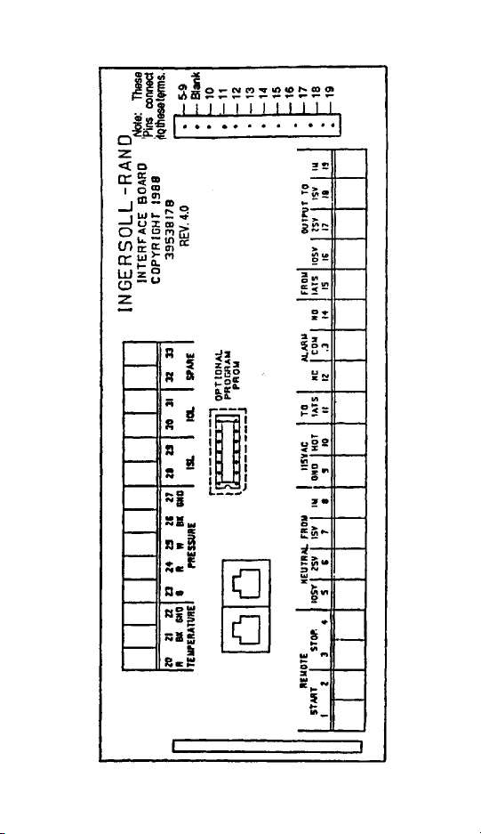
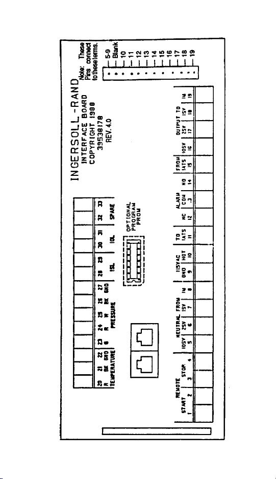
The Starter Interface Board is the transition between the electrical wiring and the
Intellisys. The large terminal strips are for field accessibility. The Starter
Interface Board is divided into a high level 115 volt AC and a 5 volt DC section.
Each terminal has been clearly identified as to its purpose.
The ribbon cables connecting the starter boards with the Intellisys controller
have been separated the same way. The larger cable is for 115 volt AC signals
-1-

and the smaller cable is for 5 volt DC signals.
This is the socket for the option prom and the communications port. Options are
activated by inserting the option prom in the socket. The prom contains
permanent memory which supplies the Intellisys controller with some additional
information required for the respective option and triggers a code in the
microprocessor.
The communications port is for communication with other Ingersoll-Rand
Products.
-2-
-3-

SENSORS
There are 2 sensors utilized on the SSR 10-40 HP range.
One is a pressure sensor.
The other is a temperature sensor.
The temperature sensor is a thermistor located in the discharge air circuit. It
comes complete with a 6 foot lead that directly connects it to the Starter Interface
Board. It connects to terminal 20 (a red wire), terminal 21 (a black wire) and
terminal 22 has an insulated ground wire.
The temperature sensor reports its values by a change in resistance. As the
resistance decreases it relates to an increase in the temperature.
The pressure sensor is a strain gauge device that terminates in a female plug.
A male plug is connected and terminates in the Starter Interface Board. The top
part of the pressure sensor is a stainless steel diaphragm that will move as
pressure increases. This movement results in a positive voltage change. The
Intellisys directly interprets this voltage to a pressure.
The cable connects to the interface board as follows:
1 green 23
2 red 24
3 white wire connects to terminal 25
4 black wire connects to terminal 26
5 ground wire 27
OPERATION
The SSR 10-40 horsepower Intellisys is delivered completely operational. All
that is required is to hook up main power to the starter and operate the
compressor. There are no adjustments required. The initial settings will vary
according to the stated operating pressure of the compressor. Please refer to
the instruction book for these values. Compressors equipped with the Intellisys
are truly plug in and run units.
Upon initial power up, all the lights on the Intellisys will light. The numeric display
will show four 8’s. This feature accomplishes 2 things. First it gives a lamp test
to insure that all the lights and all the segments in the display are functional, and
secondly, it allows the microprocessor to perform a self-check. Since the only
way all the lights can light and the display can show all 8’s is on command from
the microprocessor. If this occurs, we know that the processor is good.
When the Intellisys display shows 8888’s, pressing the SET button will clear it.
When cleared, the display will show 0 signifying that the compressor is ready to
start.
To start the compressor be sure that the display is showing 0. Pushing the start
button, the compressor will start. It will remain unloaded until the load switch has
been pressed.
Press the load switch and the compressor will load and operate in the on-line offline mode. It will continue to operate in this mode which is the most efficient
mode of operation until the load button is depressed again.
-4-

To run the compressor in modulate mode merely press the load switch again.
This will put the compressor in modulate/ACS and it will operate automatically
from this point.
Each time the load button is depressed the compressor will switch to another
mode of operation.
All Intellisys have ACS as a standard feature. On the original Intellisys however,
it was not printed on the face of the controller. The most recent controller has
Modulate/ACS printed on the face.
On the original Controller ACS operates as follows: While running in the ON/
OFF LINE MODE and the machine cycles three times in three minutes, the
controller will automatically shift to modulation. While running in the modulate
mode and the machine runs unloaded for three minutes, the controller will shift
back to ON/OFF LINE. The green LED lights will follow these shifts.
On newer Intellisys with ACS printed on the face, the controller activates the
ACS mode differently. If this controller is manually placed in the ON/OFF LINE
mode, it will stay in this mode and not shift automatically to modulate. The
controller must be placed in the Modulate/ACS Mode position in order for the unit
to modulate and shift into ON/OFF LINE if demand indicates. Unlike the original
controller, the green LED lights will not shift position.
In any mode of operation pressing the display-select button will change the value
that is being read. The legend next to the display-select is to show what is being
displayed. Each successive depression of the display-select moves the
selection down one.
After 10 minutes of no activity on the display-select, the display will automatically
revert to the default setting which is discharge air pressure.
To stop the compressor, merely press the unloaded stop button. The compressor will initially unload and operate unloaded for approximately 7 seconds at
which point it will stop. This unloaded stop has been installed to insure the most
optimal operation of the compressor.
The emergency stop button is provided for emergency operation. This device
immediately breaks the 115 volt AC supply voltage to the compressor. This
switch should be used with care since it may cause damage to the compressor.
It is truly provided for emergency purposes only.
The set button in conjunction with the up and down arrows is used to make
adjustments to the machine. In order to utilize this feature, the machine must
be stopped.
The first press of the set button will put the controller into the set mode and light
the first setable parameter, Set Off Line Air Pressure.
By pressing the up or down step arrows the value shown in the window will
change. When the desired value is selected, press the set button to fix it into
memory.
The display will shift down to the next setable parameter. The unit will loop
around when it gets to the bottom. When an option is not installed, dashes will
appear in the display.
-5- -6-

If the Intellisys is allowed to remain in the SET POINT mode with no change for
more than fifteen seconds the system will return to READY mode as announced
by the 0 in the display.
The set button also serves the functions of clearing an alarm. Pressing the set
button twice will clear the alarm.
The 2 step arrows also perform another function of calibrating the pressure
sensor. Any time the pressure sensor or controller are changed, the unit should
be re-calibrated. To re-calibrate, have the compressor off with zero pressure on
the pressure sensor and press both step arrows simultaneously once.
INDICATOR LIGHTS
The Intellisys controller features two indicator lights. One being the power-on
light and the other being the automatic re-start indicator light.
The power-on light indicates that there is 115 volt control voltage to the Intellisys.
In the event that the power light is lit and the display is blank, that indicates that
there is a fault in the Intellisys and that it has to be changed out. In the event that
the power light is not lit, but the display is lit, it means that the power-on light is
burned out. This is not a field replaceable item and the Intellisys should be
replaced.
The other indicator light is the automatic restart indicator light. This light
indicates that the compressor has shut down automatically due to the fact that
the line pressure exceeds the off-line limit that has been programmed into the
unit. With this light lit the compressor is able and probable to start at any time.
MESSAGES
The Intellisys Controller display 12 numeric fault codes in the display window,
except that some early units do not have a -12- code.
Displays 1 through 12 indicate fault annunciation with the unit. All fault
annunciation is identifiable by the preceeding and trailing dash. In other words,
the display would show a -01-.
The fault codes will only appear when an actual fault is detected. This will be
demonstrated.
MESSAGE -01- STARTER FAILURE
The way the Intellisys controller has determined whether it is a starter failure or
not is by checking the condition of the starter interlock switch. Remember to
remove all electrical power from the compressor. Lock and tag the disconnect
switch.
Upon this fault, the first thing you should do is to check the functioning of the
starter interlock switch. This can be done by removing the control wiring to the
switch and attaching a continuity checker.

If this is functioning properly, then check the functioning of the main starter coils.
This can be done by disconnecting the wires to the coil and applying 115 volts
to the coil from a near by wall outlet.
Before proceeding be sure to remove the 115 volts applied to the starter coil for
safety.
If these 2 prove to be OK, check for continuity between terminal #19 on the
starter interface board and the starter coil connection. Also check for continuity
between the opposite coil connection and terminal #8 on the starter interface
board. If these check out OK, check for continuity between #8 on the interface
board and pin 1 on the 115 volt connector. This is the white connector on the
right side of the board and pin 1 is the top most pin. Also, check for continuity
between terminal #19 on the interface board and the bottom most pin on the
white connector.
If there is no continuity between the terminals and the pins, change the starter
interface board. If there is continuity here, change the Intellisys controller.
MESSAGE -02- MOTOR OVERLOAD
If the display shows an -02- check the motor over-load for proper operation.
Remember to remove all electrical power from the compressor, lock and tag the
disconnect switch.
The overload contact circuit can be checked by removing the wiring each side
of the contact. Attach a continuity meter across the contact. Remove a heater
element and mechanically trip the internal mechanism to open the overload
contact.
If the contact is functioning properly check for continuity between terminals 30
and 31 on the starter interface board and the connections on the motor overload.
If we have continuity, proceed to the next test. Check for continuity of terminal
31 to any of the ground connections or the same terminal strip like 20 or 27. If
this proves OK, remove the 5 volt cable which is the cable on the left, the black
plug, and check for continuity between 31 and either of the bottom 2 most pins
on the connector.
Also check for continuity between terminal 30 and pin #7 on the right side of the
black connector.
If all continuity checks prove OK, and the overload checks OK, then change the
Intellisys controller.
MESSAGE -03- HIGH DISCHARGE AIR TEMPERATURE
If the display shows an-03-fault, this occurs when the temperature sensed by the
thermistor in the discharge air exceeds the value programmed into the Intellisys
controller.
First, check the value of the shutdown by pressing the display-select for
discharge air temperature. Insure this limit is in the correct range by pressing
the set button twice to clear the-03-fault, then continue pressing set until the
discharge air temperature is displayed.
-7- -8-

The range adjustment is between 200°F and 228°F. At 97% of the shutdown
value the red alarm light will start flashing.
This is a warning indication of rising temperature.
A compressor that is experiencing a higher air temperature condition may have
the following symptoms.
1. It is experiencing poor to inadequate room ventilation.
2. The compressor room ambient may exceed 100°F.
3. The coolers may be fouled with dirt.
4. Inadequate lubrication within the airend may be causing high discharge
temperature.
However, if the temperature range proves to be acceptable, check the resistance of the temperature sensor. Do this by disconnecting the cable wire from
terminals 20 and 21. Attach an OHM meter to the leads of the thermister.
Remember, the temperature must be held constant on the sensor in order to
measure a constant OHM value. The use of a thermometer may be an
advantage. Use the following table as a guide and match the OHM value to a
sensor temperature. This will verify if the temperature is good or bad.
Degree F° OHMS
50 20244
60 15475
70 11934
80 9282
90 7277
100 5748
110 4573
120 3663
130 2955
140 2400
150 1962
160 1614
170 1335
180 1110
190 928
200 780
210 658
220 558
230 476
240 407
MESSAGE -04- HIGH DISCHARGE AIR PRESSURE
When the-04-fault exists, the controller reacts to this problem by sensing the
pressure via the pressure sensor. Should this value exceed what is set into the
controller, it will shut down. Upon shutdown, the first thing to do is check the
value in the display window.

Press display select to obtain a discharge air pressure reading in the display
window. This is the shutdown pressure.
The controller can be set for 100-125-150 or 175 psig. The controller will shut
down if the discharge pressure exceeds 15 psig over any of the preset discharge
pressures programmed into the controller by the factory.
SYMPTOMS
1. The Intellisys controller does not power up, even though power is present
at the primary and secondary contacts of the transformer and interface
board or intermittent contact will give various error codes.
The cause of this is the electrical signal in the pressure transducer and can
ground itself fully or intermittently when the 4 prong adapter is installed in the
cable housing.
The spade connection at the end of the wire may contact the inner metal wire
sheath of the cable connector.
There are four wires inside the cable (red, green, black and white). Therefore,
several combinations of ground contact are possible.
TO CORRECT THE PROBLEM:
1. Loosen the nut, pull slightly on cable.
If you have a unit that is showing symptoms as described, it may be necessary
to repair or replace the existing cable.
This problem has been corrected on new units with the addition of a heat shrink
shield at the end of the transducer cable to prevent contact.
Re-assemble the connector and plug it back in.
The pressure transducer should be calibrated at start up and anytime a
component associated with the transducer or Intellisys system is replaced.
Calibration of the transducer is accomplished as follows:
1. All pressure must be removed from the pressure transducer. Be sure to
remove the tubing attached to the line sump solenoid valve.
2. The controller must be in the ready to start mode. (“O” in the display
window).
3. Press the step up/down arrows at the same time, (ONCE). When the
arrows are pressed, the green LED light on the display-select will shift to
SUMP and then return to discharge air pressure.
4. This procedure can be done anytime you suspect an error in the pressure
transducer circuit.
IT IS VERY IMPORTANT TO HAVE THE AIR PRESSURE REMOVED FROM
THE TRANSDUCER PRIOR TO CALIBRATION.
MESSAGE -05- TEMPERATURE SENSOR FAILURE
If this fault shows-05-temperature sensor failure, the Intellisys looks at the value
from the temperature sensor and checks to see if it is within a proper range. If
-9-

it is completely out of range it shuts the unit down on temperature failure. While
investigating, remember to open the electrical disconnect and lock and tag.
The next step is to press the display-select button twice and check the value of
the shutdown temperature.
If the temperature range is acceptable, check the resistance of the temperature
sensor. Do this by disconnecting the cable wires from terminals 20 and 21.
Attach an OHM meter to the leads of the thermister.
Remember the temperature must be held constant on the sensor in order to
measure a constant OHM value. The use of a therometer may be an advantage.
Use the following chart as a guide and match the OHM value to a sensor
temperature. This will verify if the temperature sensor is good or bad.
The next step is to check the continuity of the interface boards. Remember to
remove all electrical power, lock and tag. Remove the 5 volt DC ribbon cable
and check for continuity between terminal 20 and the top left most pin, and
continuity between 21 and the top right most pin. Check continuity of pin 22 to
ground, terminal 27. Also, check continuity of 22 to either of the bottom most
pins which are ground connections. If all continuity checks are good, replace
the Intellisys controller.
Remember, intermittent contact associated with the interface board may be
detected with slight flexing or elevated room ambient conditions.
Degree F° OHMS
50 20244
60 15475
70 11934
80 9282
90 7277
100 5748
110 4573
120 3663
130 2955
140 2400
150 1962
160 1614
170 1335
180 1110
190 928
200 780
210 658
220 558
230 476
240 407
MESSAGE -06- PRESSURE SENSOR FAILURE
When the-06-fault exists the Intellisys determines pressure sensor failure by
taking the reading of the sensor and checking it against some logical range. If
it is out of range, it considers the sensor to be failed.
-10-

In this case, check the male-female connection on the end of the sensor. Also
disassemble the male cable and insure that all wires are intact as was done for
fault number -04-.
Check for continuity on each wire of the cable after disconnecting it from the
interface board.
Just follow the color codes of the wires.
The most common-06-failure is a result of not having 15 pounds of sump
pressure in 10 seconds after start-up. This can be caused by a small air leak in
the tubing attached to the line sump solenoid valve or failure of the valve to
toggle. First check for leaks and check the solenoid for proper operation
including the presence of moisture or dirt in the solenoid orifice.
After checking the pressure transducer calibration and its cable for shorts, the
following procedure will tell you if the circuit through the interface board is
defective.
1. Disconnect the five leads from the pressure transducer cable at the
interface board (terminals 23 through 27).
2. Install a jumper between terminals 23 and 25.
3. With the controller in the ready to start mode (0 in the display window),
press the Step Up and Down arrows at the same time (once).
4. If an O shows in the display window the circuit through the Interface Board
is OK. If a -06-shows in the window, the board is defective and should
be replaced.
MESSAGE -07- EMERGENCY STOP
The emergency stop switch contains 2 sets of contacts. One set of contacts
completely breaks the 115 control voltage. The other set of contacts supplies
a signal to the Intellisys controller that the switch has been pressed. This display
is telling you that the switch has been pressed. To clear the emergency stop
switch, rotate the switch, clockwise, hit set twice, which resets zero in the
display. The compressor will be ready to start again.
If “set” does not clear, change the Intellisys controller.
MESSAGE -08- EMERGENCY STOP BUTTON ENGAGE
The emergency stop switch supplied with the Intellisys controller is a twist to
unlock unit. This fault appears when the-07-message appears and the operator
has pressed the set switch to clear it without disengaging the stop switch. When
still engaged, the Intellisys controller will scan the contacts and realize that it is
still depressed and will not allow starting.
To correct this, the emergency stop switch must be disengaged.
-11-

MESSAGE -09- MICROPROCESSOR FAILURE
The CPU Printed Circuit Board Assembly contains a circuit called the watchdog.
The way the watchdog functions is that on each cycle of the program, it signals
the watchdog that it is functioning OK. The watchdog starts a timer. If before
the timer times out, the program has not come back and signaled the watchdog,
the watchdog shuts the unit down as a microprocessor failure. It may or may not
be a true indication of a failure. In the event of an -09- signal, please follow the
following steps.
First disconnect power to the unit by opening the disconnect switch.
Re-energize the unit and look at the display. The display should come up all 8’s
with all the lights lit. As we stated earlier in this training, that means that the
microprocessor is OK.
Press set to clear the unit and press start to start the compressor. If on powerup, any of the lights do not come up or any of the 8’s do not come up, it indicates
that there is a potential microprocessor failure.
To confirm a -09- message disconnect the wires from terminals 9 and 10 on the
starter interface board. Connect a 115 volt extension cord and plug it into a
nearby wall outlet. Reset the Intellisys as stated earlier. If Intellisys functions
okay the problem is in the incoming power. If the Intellisys shuts down with -09, change the Intellisys.
MESSAGE -10- REMOTE STOP ENGAGE
The above feature tells the operator that the unit has a remote start and stop
feature installed. The fault occurs when the remote stop button is open or a
remote wire is loose, open or broken.
MESSAGE -11- LOW VOLTAGE
The Intellisys System provides a more accurate method of monitoring input
electrical voltage to the controller than any hand held meter. Conditions that
allow the incoming electrical power to the controller to drop to 85% of 115 volts
or less will shut the compressor down within one electrical cycle. Should this
fault occur, check the line voltage for a value.
Conditions that may contribute to low voltage would include undersize wiring,
incorrect or undersize step down transformer or undersize step up/step down
transformer.
Open the compressor disconnect switch, and lock and tag the panel prior to
changing any wiring. One test that can be performed is to remove the 115 volt
power from the transformer, at terminal 9 and 10 on the interface board. Tape
the wire for safety. Be sure to supply the positive lead to terminal 10 on the
interface board. Failure to do this will damage the board. Re-apply power, set
0 in the display and try to restart the compressor. If the Intellisys unit powers up
and the compressor can be operated in a normal manner this indicates that the
primary and secondary voltages were too low and must be corrected.
Below 80 volts the display will show blinking 8888’s and the green LED light will
also blink.
-12-

MESSAGE -12- INCORRECT COMPRESSOR ROTATION
Generally this fault will only occur during initial start up where the operator has
connected the cables wrong so that the compressor is being driven backwards.
Check the main incoming and power leads to insure that they are correct.
In earlier versions the controller will try to read a positive 10 psig sump pressure
in the first 3 seconds of operation. If it does not see this pressure it will assume
the unit is rotating backwards and can not develop pressure.
This condition can also exist when the flexible tubing attached to the line sump
solenoid is not inserted into the fittings completely and a small air leak exists.
Foreign material inside the solenoid valve orifices can also prevent a pressure
build up and the fault will occur.
Refer to the Intellisys Field Service Sheet No. 9.
Certain SSR 10-40 units may not develop adequate sump pressure of 10 psi (or
more) within 3 seconds of a manual start up. When this happens the unit shuts
down and indicates -12- (reverse rotation) on the display even though rotation
is correct.
To help alleviate this potential situation, we are revising the logic within the
Intellisys to look for a positive pressure within 3 seconds of start up. This will
eliminate the nuisance shutdown on -12- in these instances.
To secure this new revision level Intellisys Controller, order Kit No. 39679097.
This is for a factory re-manufactured controller and should be used when making
warranty repairs. We also have the capability of programming into the controller
appropriate load and unload hours to match units operating in the field. Specify
this requirement with your order if it is an important consideration.
Keep in mind that the parts manual also lists a new controller, P/N 39786470
order Kit No. 39668793. It will also have the new software feature described
above, but with zero hours running time. When making field repairs, it is
necessary to order gasket P/N 39786413. (Included in 39679097 and 39668793
Kits)
An order must be placed on Davidson for these parts, and the controller will be
shipped out of Davidson.
Units shipped after January 2, 1990 will have the reverse rotation revision
described above. Units manufactured prior to this date will not have the feature
described.
LOSS OF ELECTRICAL POWER
If this happens all 8888’s will appear in the display. This occurs when the
electrical power is interrupted for 250 milliseconds, which is equivalent to 15
cycles of electrical power. A conventional volt meter can not respond quickly
enough to detect this. However, the Intellisys can.
"Intellisys made after August 31, 1990 (Rev 9.0) go to 'ø' ready to start."
8888's
-13- -14-
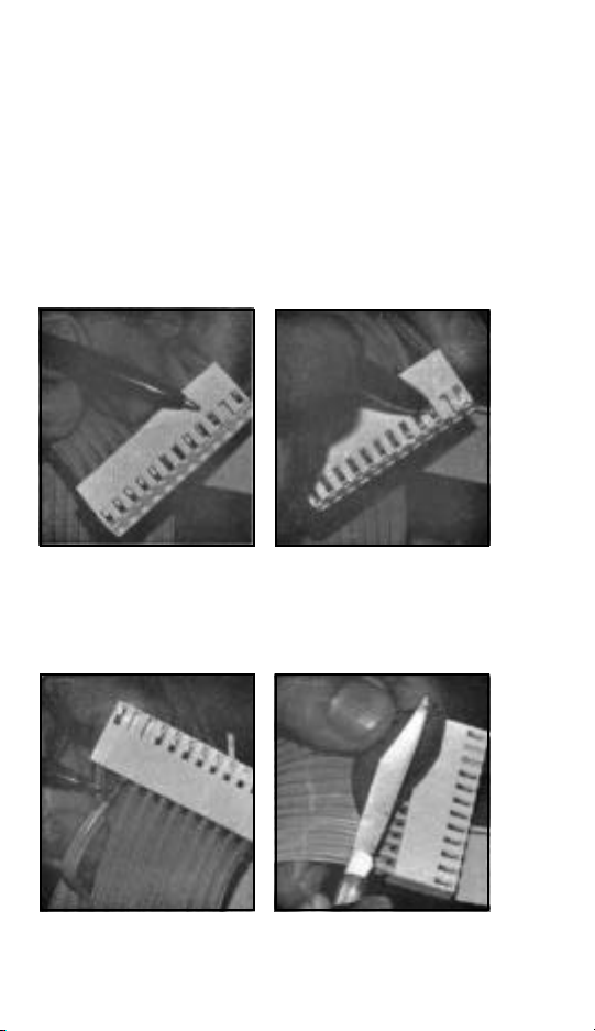
If you experience intermittent shut downs on the Intellisys equipped units,
indicated by the appearance of all 8888’s or-01-in the display window, check the
female connector on the gray ribbon.
We have learned that this connector may not be making a good contact with the
male pins on the interface boards.
To correct the problem, remove the female connector from the interface board,
look into the connector holes, if any of the contactors are depressed or appear
not to be making a good contact follow this procedure to effect the repair.
1. Remove the gray ribbon cable connector from the interface board.
2. Identify the connector that is not
making good contact with the interface connector pin.
4. The socket will slide out of the
plastic housing.
3. Remove the connector socket by
pressing on the latch while pulling
on the wire.
5. Make sure the latch is bent back
to the original position.
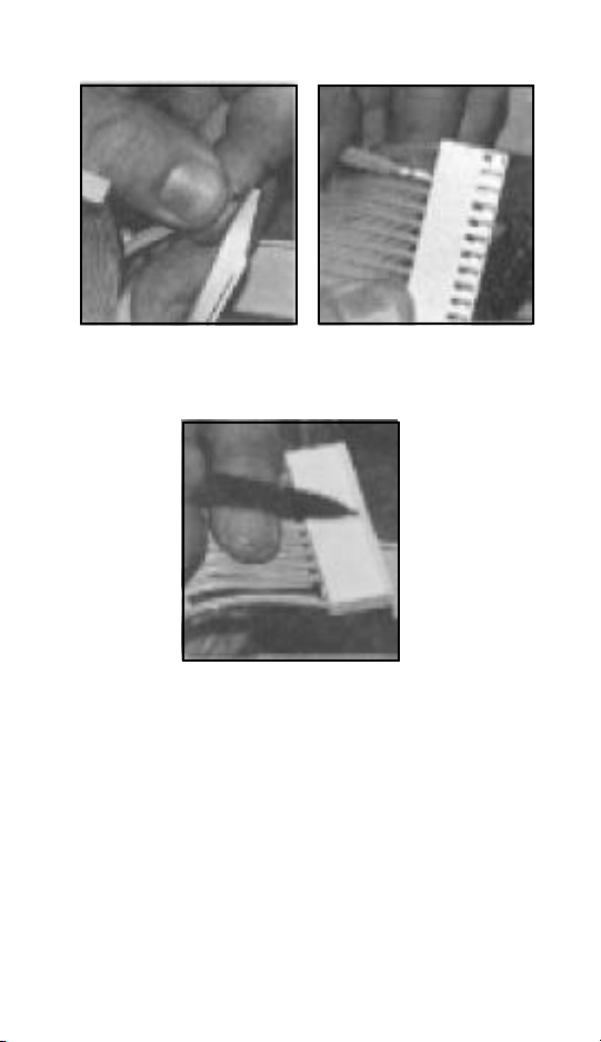
6. Bend an arc back into the socket
connector to insure good contact
with the mating pin.
8. Make sure that the beveled latch
on the connector latches with the
mating half on the interface board.
Another symptom causing all 8888's is that even though power is present at the
primary and secondary contacts of the transformer, intermittent contact can
cause shutdown within the control circuit.
The electrical signal in the pressure transducer can ground itself fully or
intermittently when the compressor is operating.
The spade connection at the end of the wire may contact the inner metal wire
sheath of the cable connector.
There are four wires inside the cable. Therefore several combinations of ground
contact is possible.
7. Slide the socket connector back
into the plastic housing. You can
hear the latch click when it is all the
way in.
-15- -16-

To check for a grounded cable condition, remove the ground wire on Terminal
27. Before performing this function, disconnect all electrical power, lock and tag.
Run the compressor and if it continues to run, then this is an indication that the
transducer cable is defective and should be repaired or replaced. Remember,
to reconnect the ground connection on Terminal 27 after the test and repair is
complete.
INTELLISYS HOUR TIMER
During the first hour of compressor operation, the Intellisys is counting in
minutes only. If a decimal is showing the unit is timing in minutes.
There are three 20 minute increments in the first hour.
20-40-60
If the power is interrupted in any of the 20 minute increments, the time goes back
to the last elapsed time 20 minute period.
Example: The unit has 21 minutes and the power is removed from the unit. The
timer will go back to the 20 minutes.
Notice the Intellisys panel showing 59 minutes of accumulated time. The display
will change over to 1 hour and continue recording in 1 hour increments.
OPTION INSTALLATION AUTO STOP/START
For those plants which have a widely varying plant air demand, larger air storage
capacity and/or want automatically available standby air capacity, Automatic
Stop/Start Control Option is available.
During periods of low demand, if the line pressure rises to the off line set point
of Intellisys controller, a timer is energized and begins to time out. The automatic
stop time is adjustable in a 10-30 minute range. The timer will continue to

operate as long as the plant line-pressure remains above the on line set point
of the Intellisys controller.
If the timer continues to operate for as long as its adjusted time setting, a relay
contact in the Intellisys opens to de-energize the compressor motor starter coil.
At the same time, an amber light on the Intellisys panel is lit to indicate the
compressor has shut down automatically and will restart automatically.
The automatic restart will take place when the line pressure drops to the on line
set point of the Intellisys controller.
INSTALLATION INSTRUCTIONS:
Remove the option prom (39666672) from its package, using care not to
damage the pins on the prom.
Insert the prom into the optional program prom socket located in the center of
the interface board as shown in Figure 1. (Pin #1 on the prom should be located
in the lower left corner for correct installation).
Set the automatic stop time on the Intellisys panel. Press the set button to
initialize the prom function.
Start the compressor and adjust the isolation valve to allow the unit to slowly
reach the off line pressure and unload. The compressor should run for the preset time and then shut down.
The compressor should restart automatically when system air pressure drops
below the on line air pressure setting.
OPTION INSTALLATION REMOTE STOP/START
The remote stop/start option allows the operator to control the compressor from
a remote mounted stop/start station. Two different terminal points are provided
on the interface board, one a connection for a normally closed stop switch
(terminals 3 and 4) and one for a normally open, momentary contact start switch
(terminals 1 and 2).
-17-

For safety, a selection is available in the Intellisys setpoints to disable the remote
stop and start switches. This allows the compressor to be fully controlled by the
Intellisys controller and not from the remote stop/start station.
If the remote start switch is momentarily closed, the Intellisys controller starts the
compressor. The remote stop switch is normally closed. If the remote stop
switch opens, the compressor will do an unloaded stop. The compressor cannot
restart until the remote stop switch has been reset to a closed position.
The compressor must be loaded initially at the Intellisys in order for it to be
loaded remotely.
Also on a power outage the compressor panel must be reset locally in order for
the remote stop/start to control the compressor.
INSTALLATION INSTRUCTIONS:
Remove the option prom* from its package, using care not to damage the pins
on the prom.
Insert the prom into the optional program prom socket located in the center of
the interface board as shown in Figure 1. (Pin #1 on the prom should be located
in the lower left corner for correct installation).
Connect the remote stop and start switch wiring to terminals 1-4 on the interface
board. Terminals 1 and 2 are labeled “start”, 3 and 4 are labeled “stop”.
Select remote stop/start function on the Intellisys controller. “0000” in the
display, indicates remote stop/start is disabled “1111” in the display indicates
remote stop/start is activated.
Remember to push the set button once to initialize the prom function.
*ITEMS NOT SOLD SEPARATELY, FOR REPLACEMENT PARTS ORDER
KIT NO. 39666680.
-18-
-19- -20-
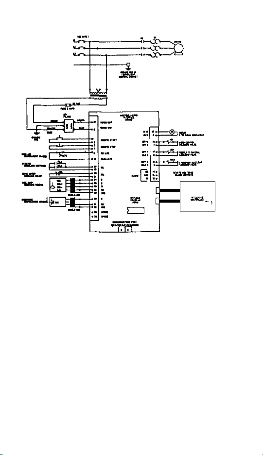
WIRING SCHEMATIC
Refer to Page 30 for Schematic
INTELLYSIS CONTROLLER INACTIVATED
The photo on page 21 illustrates a condition that can render the Intellysis
controller inoperative; display error codes 01 through 06 or 8’s appearing on the
display.
SYMPTOMS:
1. The Intellysis controller does not power up, even though power is present
at the primary and secondary contacts of the transformer and interface
board or intermittent contact will give various error codes.
CAUSE:
The electrical signal in the pressure transducer can ground itself fully or
intermittently when the 4 prong adopter is installed in the cable housing.
The spade connection at the end of the wire may contact the inner metal
wire sheath of the cable connector. Note photo A on page 21.
There are four wires inside the cable (red, green, black, white). Therefore
several combinations of ground contact is possible. Note photo B on
page 21.
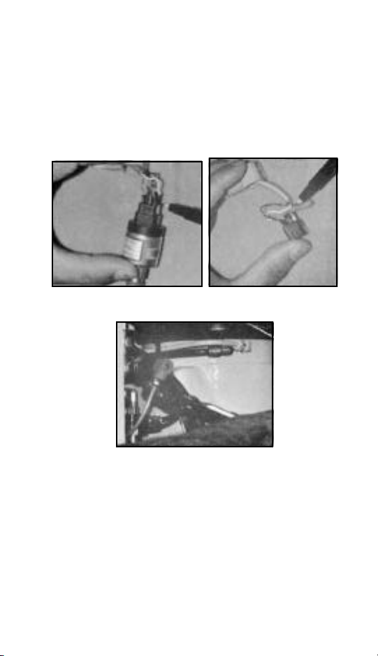
TO CORRECT THE PROBLEM:
1. Loosen nut A. Pull slightly on cable B. See photo C below.
If you have a unit that is showing symptons as described, contact the
customer service department in Davidson. It may be necessary to repair
or replace the exisiting cable.
This problem has been corrected on new units with the addition of a heat
shrink shield at the end of the transducer cable to prevent contact.
A B
C
IMPORTANT NOTICE
AUTO CONTROL SELECTOR
10 - 40 Horsepower
ACS and how it is activated on the Intellisys controller.
The original Intellisys has ACS (Automatic Control Selector), however, it was
not printed on the face/membrane of the controller. The most recent
controller has modulate/ACS printed on the face.
-21- -22-

The operation of ACS is as follows: Original Controller. While running in the ON/
OFF LINE MODE, and the machine cycles three times in three minutes, the
controller will automatically shift to modulation. While running in the modulate
mode and the machine runs unloaded for three minutes the controller will shift
back to ON/OFF LINE. The green LED lights, will follow these shifts.
The most recent controller activates the ACS mode differently. If this controller
is manually placed in the ON/OFF Line Mode, it will stay in this mode and not shift
automatically to modulate.
The controller must be placed in the modulate / ACS Mode position in order for
the unit to modulate and shift into ON/OFF line if demand dictates. Unlike the
original controller, the green LED lights will not shift position.
INTELLISYS CODE-12-SHUTDOWNS
SSR 10-40 Horsepower
Code 12 is activated by the pressure transducer which must sense 10 psig sump
pressure within three seconds after depressing the start button.
If 10 psig sump pressure is not developed within the three second interval, the
controller thinks the compressor is running in reverse rotation and will shut the
unit down and display CODE 12.
If any positive pressure is displayed on the controller, the rotation is correct.
Any leakage in the tubing, fittings or line/sump solenoid valve could prevent the
true sump pressure from reaching the transducer within the 3 second time period
and should be checked prior to changing any components.
If “0” psig sump pressure is displayed during startup, check terminals 5 and 16
on the Interface Board to confirm that 115 volts is being supplied to the (10SV)
line/sump solenoid. A defective (10SV) would not shift to sump during startup,
which would also show “0” psig pressure.
TRANSDUCER CALIBRATION
SSR (10-40 Horsepower With Intellisys Controller)
The Pressure Transducer should be calibrated at Start-Up, and anytime a
component associated with the transducer or Intellisys system is replaced.
Calibration of the transducer is accomplished as follows:
1. All pressure must be removed from the pressure transducer.
2. The Controller must be in the ready to start mode. (“0” in the Display
Window).
3. Press the Step Up and Down Arrows at the same time, (ONCE). When
the arrows are pressed, the Green LED light on the Display Select will
shift to Sump and then return to Discharge Air Pressure.
4. This procedure can be done anytime you suspect an error in the pressure
Transducer circuit.

NOTE: IT IS VERY IMPORTANT TO HAVE THE AIR PRESSURE REMOVED
FROM THE TRANSDUCER PRIOR TO CALIBRATION.
INTELLISYS INTERFACE BOARD
(SSR 10-40 Horsepower)
Some of the Rev. 3.0 Interface Boards give symptoms of intermittent contact and
open circuits. This can result in various error codes displayed on the Intellisys.
We have learned that the Rev. 3.0 Board has had broken and cold solder joints.
The new Rev. 4.0 should correct this problem.
The Rev. 3.0 and 4.0 have the same I-R part number 39538178. The Rev. 3.0
should no longer be in stock in Davidson Parts Center.
Do not replace the Rev. 3.0 Interface Board unless you have experienced
problems with it.
Contact Customer Service Department in Davidson for techniques in
troubleshooting defective Interface Boards.
INTERFACE BOARD TEST PROCEDURE
Procedure for testing the 115V circuits in the Interface Board
We have experienced problems with different components not operating
electrically. These components could be the 1M contactor, 1SV Load Solenoid,
2SV Modulate Solenoid, and 10SV Line/Sump Solenoid. The problem could be
in an open circuit, or cold solder joint in the Interface Board. The following test
should help in troubleshooting these problems:
1. Remove the power from the machine.
2. Disconnect the two ribbon cables from the Interface Board.
3. As an example, assume you are having a problem with the 1M Contactor
not pulling in. Take an extension cord and connect the two leads to
terminals 8 and 19. Plug in the cord. The contactor should pull in. If it
does, unplug your cord and reconnect the leads in the pins on the white
connector that connect to terminals 8 and 19, (see diagram 1).
4. Plug in your extension cord if the 1M contactor does not pull in. The
Interface Board is open on this particular circuit and should be replaced.
5. This test can be done on all of the 115V components that connect to the
Interface Board. Use diagram 1 to determine connection points.
-23- -24-
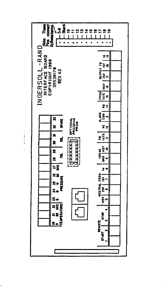
DIAGRAM 1

INTERFACE BOARD TEST FOR PRESSURE SENSOR
Shut downs may occur that display an error code of -06- and -12-. After checking
the pressure transducer calibration, and its cable for shorts, the following
procedure will tell you if the circuit through the interface board is defective.
1. Disconnect the five leads from the pressure transducer cable at the
interface board (terminals 23 through 27).
2. Install a jumper between terminals 23 and 25.
3. With the controller in the ready to start mode (0 in the display window).
Press the Step Up and Down arrows at the same time (once).
4. If an 0 shows in the display window the circuit through the Interface Board
is OK. If a -06- shows in the window, the board is defective and should
be replaced.
FAILURE
NUISANCE SHUTDOWNS ON 12
Certain SSR 10-40 units may not develop adequate sump pressure of 10 psi (or
more) within 3 seconds of a manual start up. When this happens the unit shuts
down and indicates -12- (reverse rotation) on the display even though rotation
is correct.
To help alleviate this potential situation, we are revising the logic within the
Intellisys to look for a positive pressure within 3 seconds of start up. This will
eliminate the nuisance shutdown on -12- in these instances.
To secure this new revision level Intellisys Controller, order kit 39679097. This
is for a factory re-manufactured controller and should be used when making
warranty repairs. We also have the capability of programming into the controller
appropriate load and unload hours to match units operating in the field. Specify
this requirement with your order if it is an important consideration.
Keep in mind that the parts manual also lists a new controller, order kit
39668793. It will also have the new software feature described above, but with
zero hours running time. When making field repairs, it is necessary to order
gasket P/N 39786413. (Included in kits)
An order must be placed on Davidson for these parts, and the controller will be
shipped out of Davidson.
Units shipped after January 2, 1990 will have the reverse rotation revision
described above. Units manufactured prior to this date will not have the feature
described.
SSR 10 - 40 LOW VOLTAGE CONDITIONS
The Intellisys System provides a more accurate method of monitoring input
electrical voltage to the controller than any hand held voltmeter. Conditions
that allow the incoming electrical power to the controller to drop to 97 volts or
less will shut the compressor unit down within 1 electrical cycle.
-25-
Conditions that may contribute to low voltage would be undersize wiring,
incorrect or undersize step down transformer or undersize buck boost
transformers.
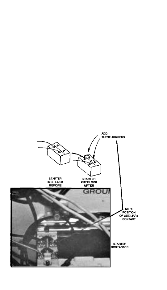
SSR 10-40 HORSEPOWER
NUISANCE -01- SHUTDOWN PROBLEM
Presently, the starter auxiliary contact is used by the controller to determine
starter operation.
It has been determined that the auxiliary contact may be one of the causes of
Nuisance -01- Shutdowns.
Due to vibration and/or corrosion, these contacts can momentarily open causing
the -01- shutdown.
The solution to this problem is to use both sets of normally open contacts. This
can be accomplished by adding two jumpers to the auxiliary contact. (See
Picture)
-26-
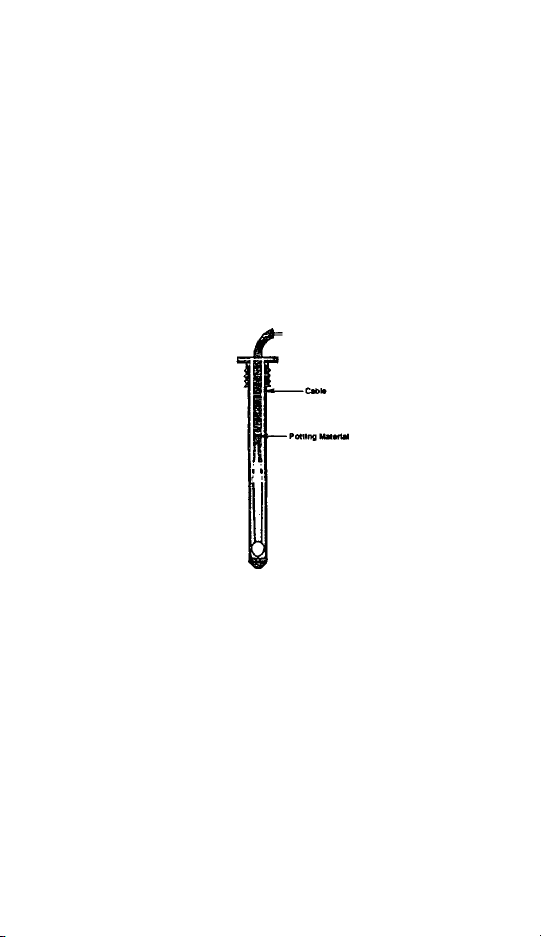
LOOSE CABLE IN TEMPERATURE SENSOR
Please be advised that we have determined a potential field failure may exist in
the temperature sensor.
Units affected are:
Visual inspection of the thermistor (sensor) cable will reveal that the shielded
cable is loose within the body of the thermistor caused by the potting material
(epoxy) that does not bond to the cable.
Moving the cable may also reveal excessive play between the cable and the
potting material at the end of the thermistor body.
This allows the wires to break or short out within the thermistor body.
On units built after July 13, 1990, the problem has been corrected. Some
temperature sensors supplied before this date may be suspect.
Replacement cables are available from Davidson.
Following normal procedures for returned materials, please return the defective
cables to Davidson Reliability Engineering, to the attention of Jeff Meadows.
Order replacement cables as required using the same part number supplied in
the manuals.
Part number 10-40U Intellisys temperature sensor 39538079.
50-200 Intellisys temperature sensor 39541677.
SSR 10 - 40 Horsepower
SSR 50 - 200 Horsepower
BEFORE STARTING PROCEDURE CHANGE
Since September 1, 1990 on all SSR 10-40 horsepower units, the BEFORE
STARTING procedure changed. These units are equipped with the latest E
Prom Revision 9.0.
-27-
 Loading...