

Ingersoll-Rand HRD20-C, HRD25-C, HRD30-C, HRD35-C, HRD40-C Operator's Instruction Manual
...
HEATLESS COMPRESSED
AIR DRYERS WITH
COMPU-PURGE CONTROL
HRD SERIES
Before installation or starting the dryer for the
first time, study this manual carefully to obtain
a clear knowledge of the unit and of the duties
to be performed while operating and
maintaining the unit.
RETAIN THIS MANUAL WITH UNIT.
HRD2-C
HRD5-C
HRD10-C
HRD15-C
HRD20-C
HRD25-C
HRD30-C
HRD35-C
HRD40-C
HRD45-C
HRD50-C
HRD55-C
HRD60-C
HRD65-C
OPERATOR’S
INSTRUCTION MANUAL
HRD70-C
HRD75-C
HRD80-C
HRD85-C
HRD90-C
HRD95-C
This technical manual contains IMPORTANT
SAFETY DATA and should be kept with the
dryer at all times.
Bulletin 342 Revision E (7/97)
Ingersoll-Rand Company 1997

Table Of Contents
INTRODUCTION . . . . . . . . . . . . . . . . . . . . . . . . . . . . . . . 1
SAFETY . . . . . . . . . . . . . . . . . . . . . . . . . . . . . . . . . . . . . 1
INSTALLATION . . . . . . . . . . . . . . . . . . . . . . . . . . . . . . . . 1
Receiving and Inspection. . . . . . . . . . . . . . . . . . . . . . . . 1
Handling . . . . . . . . . . . . . . . . . . . . . . . . . . . . . . . . 2
Ambient Air Temperature . . . . . . . . . . . . . . . . . . . . . . . 2
Location and Clearance. . . . . . . . . . . . . . . . . . . . . . . . . 2
System Arrangement . . . . . . . . . . . . . . . . . . . . . . . . . . 2
Piping and Connections . . . . . . . . . . . . . . . . . . . . . . . . 2
Desiccant . . . . . . . . . . . . . . . . . . . . . . . . . . . . . . . . 3
Mufflers. . . . . . . . . . . . . . . . . . . . . . . . . . . . . . . . . 4
Electrical Connections . . . . . . . . . . . . . . . . . . . . . . . . . 4
INDICATORS. . . . . . . . . . . . . . . . . . . . . . . . . . . . . . . . . . 4
Additional Indicators and Alarms . . . . . . . . . . . . . . . . . . . 5
OPERATION . . . . . . . . . . . . . . . . . . . . . . . . . . . . . . . . . . 5
How It Works. . . . . . . . . . . . . . . . . . . . . . . . . . . . . . 5
Compu-Purge Control . . . . . . . . . . . . . . . . . . . . . . . . . 6
Start-Up. . . . . . . . . . . . . . . . . . . . . . . . . . . . . . . . . 6
Dew Point Verification . . . . . . . . . . . . . . . . . . . . . . . . . 7
MAINTENANCE . . . . . . . . . . . . . . . . . . . . . . . . . . . . . . . . 7
Desiccant Dusting . . . . . . . . . . . . . . . . . . . . . . . . . . . 7
Shutdown . . . . . . . . . . . . . . . . . . . . . . . . . . . . . . . . 8
Maintenance Schedule . . . . . . . . . . . . . . . . . . . . . . . . . 8
Daily . . . . . . . . . . . . . . . . . . . . . . . . . . . . . . . 8
Weekly . . . . . . . . . . . . . . . . . . . . . . . . . . . . . . 9
Yearly . . . . . . . . . . . . . . . . . . . . . . . . . . . . . . 9
Returns to Manufacturer . . . . . . . . . . . . . . . . . . . . . . . . 9
Desiccant Replacement. . . . . . . . . . . . . . . . . . . . . . . . . 9
High-Humidity Alarm Field Adjustment . . . . . . . . . . . . . . . 10
Care of Compu-Purge Sensors . . . . . . . . . . . . . . . . . . . . 11
LCD Display Information. . . . . . . . . . . . . . . . . . . . . . . 12
Indicators and Alarms. . . . . . . . . . . . . . . . . . . . . . . . . 12
FIELD SERVICE GUIDE . . . . . . . . . . . . . . . . . . . . . . . . . . 13
COMPU-PURGE CONTROL BOARD SERVICE LAYOUT. . . . . . . 14
COMPU-PURGE POWER BOARD SERVICE LAYOUT . . . . . . . . 15
ELECTRICAL SCHEMATIC . . . . . . . . . . . . . . . . . . . . . . . . 16
REPLACEMENT PARTS . . . . . . . . . . . . . . . . . . . . . . . . . . 17
MATERIAL SAFETY DATA SHEET (Molecular Sieve) . . . . . . . . . 20
MATERIAL SAFETY DATA SHEET (Activated Alumina). . . . . . . . 22

INTRODUCTION
HRD Series heatless desiccant compressed air dryers
equipped with Compu-Purge
from compressed air to achieve a standard pressure dew
point of –40°F or an optional dew point of –100°F. The
heatless dryer supplies a continuous flow of dry compressed air by alternately cycling the airflow through
two desiccant beds; one adsorbs moisture from the inlet
air while the other is regenerated by a portion of the dry
air from the active bed.
To ensure continuing good dryer performance and safe
operation, everyone who installs, uses or maintains the
dryer must read and carefully follow the instructions in
this manual. Throughout the manual, the word dryer is
used to refer to HRD Series heatless air dryers.
®
control remove moisture
5. Never perform electrical service on the dryer unless
the main power supply has been disconnected. Parts
of the control circuit may remain energized when
the power switch is turned off.
6. Use only genuine replacement parts from the manufacturer. The manufacturer bears no responsibility
for hazards caused by the use of unauthorized parts.
Safety instructions in this manual are boldfaced for emphasis. The signal words DANGER, WARNING and
CAUTION are used to indicate hazard seriousness levels as follows:
DANGER—Immediate hazard which will result in
severe injury or death.
WARNING—Hazard or unsafe practice which could
result in severe injury or death.
SAFETY
HRD Series dryers are designed and built with safety as
a prime consideration; industry-accepted safety factors
have been used in the design. Each dryer is checked at
the factory for safety and operation. The desiccant vessels are hydrostatically tested to 1½ times the maximum
pressure in accordance with ASME code requirements.
A factory-installed safety relief valve is standard on
each dryer.
WARNING
The following safety rules must be observed
to ensure safe dryer operation. Failure to
follow these rules may void the warranty or
result in dryer damage or personal injury.
1. Never install or try to repair any dryer that has been
damaged in shipment. See the Receiving and Inspection instructions in this manual for appropriate
action.
2. Never operate the dryer at pressures or temperatures
above the maximum conditions shown on the data
plate.
3. Always supply electrical power that complies with
the voltage shown on the data plate.
4. Never dismantle or work on any component of the
dryer or compressed air system under pressure.
Vent internal air pressure to the atmosphere before
servicing.
CAUTION—Hazard or unsafe practice which could
result in minor injury or in product or property damage.
The dryer data plate, attached to the left side of the electrical control box, contains critical safety and identification information. If the data plate is missing or defaced,
immediately contact your local distributor for a replacement.
INSTALLATION
Receiving and Inspection
Immediately upon receipt of the dryer, thoroughly inspect for damage that may have occurred during shipping. Since the dryer is shipped F.O.B. New Castle,
Delaware, the carrier is legally responsible for damage
incurred during shipping. Shipping damage is not covered by the dryer warranty.
If goods are received short or damaged, notify the carrier and insist on a notation of the loss on the face of the
bill of lading. Otherwise no claim can be enforced
against the carrier.
If concealed loss or damage is discovered, notify the
carrier at once and request an inspection. The carrier
will make an inspection and grant a concealed damage
notation. The carrier will not consider any claim for loss
or damage unless an inspection has been made. If you
give the carrier a clear receipt for goods that have been
damaged or lost in transit, you do so at your own risk
and expense.
HRD Series Heatless Dryer with Compu-Purge Control (Bulletin 342) 1

If there is any damage, file a claim with the carrier, then
call your local distributor for further instructions.
Handling
The dryer is designed to be moved by means of the
shipping skid or the base channels. Handle the dryer
with care and only with equipment capable of lifting the
load.
Ambient Air Temperature
Locate the dryer under cover in an area where the ambient air temperature is between 35°F and 120°F. Ambient temperatures over 100°F can be tolerated but will
adversely affect dryer performance. If ambient temperatures below 35°F cannot be avoided, contact your local
distributor.
Location and Clearance
Install the dryer on a level pad. The dryer is provided
5
with a minimum
⁄8-inch diameter anchor bolt holes. For
dryers HRD2-C thru HRD35-C, anchor the dryer to the
floor with four ½-inch diameter bolts with a minimum
4-inch thread engagement. For dryers HRD40-C thru
HRD100-C, anchor the dryer to the floor with four
¾-inch diameter bolts with a minimum 6-inch thread
engagement. Allow 24 inches clearance on all sides of
the dryer for servicing. Provide adequate clearance for
prefilter and afterfilter element replacement. Provide
protection for the dryer if it is installed where heavy vehicles or similar portable equipment is likely to cause
damage.
System Arrangement
Install the dryer downstream of an aftercooler and separator so that the dryer inlet air is between 60°F and
120°F and contains no liquid water. Liquid water and/or
inlet air temperatures above 100°F can reduce drying
capacity. Contact your local distributor for information
on proper dryer sizing at elevated inlet air temperatures.
Oil contaminates the desiccant, reducing drying efficiency and desiccant life. If the inlet air to the dryer
contains oil, an oil-removing filter must be installed at
the dryer inlet. If the inlet air is oil-free, a particulate
prefilter should be installed to remove dirt and other
solid particles. A particulate filter should be installed at
the dryer outlet to capture desiccant particles.
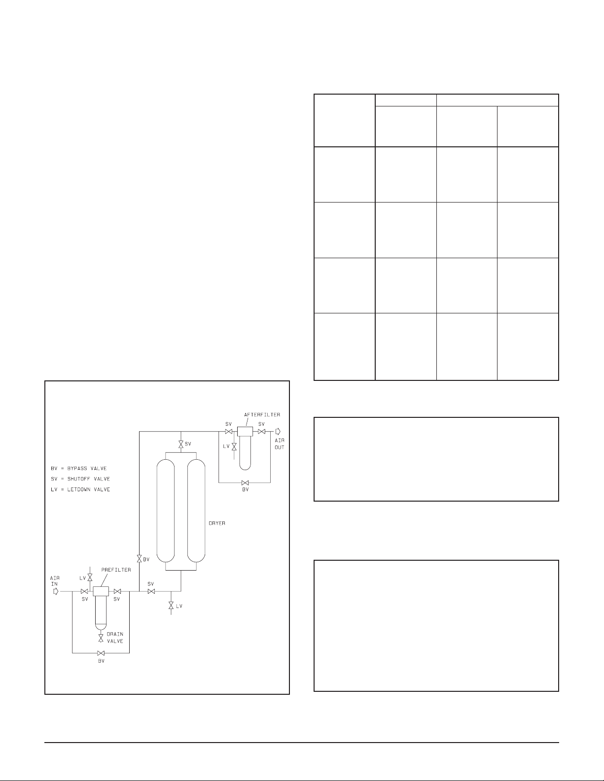
Piping and Connections
All external piping must be supplied by the user unless
otherwise specified. Refer to Table 1 for connection
sizes. Inlet and outlet manual shutoff valves and a vent
valve are recommended so the dryer can be isolated and
depressurized for servicing. Refer to Figure 1 for recommended piping layout. The connections and pipe fittings must be rated for or exceed the maximum
operating pressure given on the dryer data plate and
must be in accordance with industry-wide codes.
Table 1
CONNECTIONS
Model
HRD2-C 1
HRD5-C 1
HRD10-C 1
HRD15-C 1½
HRD20-C 1½
HRD25-C 2
HRD30-C 2
HRD35-C 2
HRD40-C 3
HRD45-C 3
HRD50-C 3
HRD55-C 3
HRD60-C 3
HRD65-C 4" FLG
HRD70-C 4" FLG
HRD75-C 4" FLG
HRD80-C 4" FLG
HRD85-C 6" FLG
HRD90-C 6" FLG
HRD95-C 8" FLG
HRD100-C 8" FLG
In/Out
Connections
(inches NPT)
Be sure all piping is supported. Do not allow the weight
of any piping to bear on the dryer or filters. Piping must
be the same size as or larger than the dryer connections.
Piping smaller than the dryer connections will cause
high pressure drop and reduce drying capacity.
If the purge exhaust muffler piping must be extended
outside the dryer area, the piping must be sized so that it
will cause no back pressure. Back pressure reduces
the capacity of the dryer. Consult your local distributor for piping details if required.
Dryer bypass piping may be installed to allow uninterrupted airflow during servicing. If the downstream application cannot tolerate unprocessed air for short
periods, install a second dryer in the bypass line.
CAUTION
Do not hydrostatically test the piping with the
dryer in the system. The desiccant will be
damaged if saturated with water.
2 HRD Series Heatless Dryer with Compu-Purge Control (Bulletin 342)
Desiccant
Standard dryers, which dry to a –40°F pdp, use activated alumina as the desiccant in the dryer vessels.
Models HRD2-C through HRD35-C are shipped with
activated alumina in the dryer vessels. Activated alumina is shipped loose with all other standard models.
Dryers that dry to a –100°F pdp (designated by the suffix J in the model number) use activated alumina and
molecular sieve in the dryer vessels.
Models HRD2-CJ through HRD35-CJ are shipped with
activated alumina in the dryer vessels. Molecular sieve
for these models is shipped loose. Activated alumina
and molecular sieve are shipped loose with all other
–100°F pdp models.
All desiccant and molecular sieve shipped loose must
be added to the dryer vessels before the dryer is put
into service.
Refer to Table 2 for desiccant type and quantity per vessel.
sel)
Table 2
(lbs per ves-
Activated
Alumina
sel)
Molecular
Sieve
(lbs per ves-
DESICCANT REQUIREMENTS
–40°F PDP –100°F PDP
Dryer Model
HRD2-C 28 19 8
HRD5-C 60 40 16
HRD10-C 95 65 27
HRD15-C 120 80 33
HRD20-C 165 110 46
HRD25-C 210 140 58
HRD30-C 285 190 79
HRD35-C 366 250 101
HRD40-C 475 325 133
HRD45-C 600 400 165
HRD50-C 725 500 200
HRD55-C 875 575 238
HRD60-C 1,025 675 282
HRD65-C 1,200 800 330
HRD70-C 1,366 911 379
HRD75-C 1,567 1,045 435
HRD80-C 1,828 1,219 508
HRD85-C 2,495 1,663 693
HRD90-C 3,205 2,150 890
HRD95-C 4,075 2,717 1,132
HRD100-C 5,126 3,425 1,425
Activated
Alumina
(lbs per ves-
sel)
To add desiccant:
WARNING
The following procedure provides
instructions for adding the initial desiccant to
the vessels. If replacing desiccant, refer to the
instructions on page 9. Pressure gauges on
both vessels must indicate 0 psig.
1. Remove the pipe plug from the desiccant fill port at
the top of each vessel. The fill ports are labeled
“DESICCANT INSPECTION PORT.”
CAUTION
Pouring desiccant creates a fine dust; safety
goggles, gloves and dust mask should be
worn by personnel installing desiccant. Refer
to the Material Safety Data Sheets (MSDS) on
pages 20 - 24 for more complete information.
Do not tamp the desiccant in vessels.
Tamping damages desiccant and causes
dusting.
RECOMMENDED PIPING LAYOUT
Figure 1
HRD Series Heatless Dryer with Compu-Purge Control (Bulletin 342) 3
2. Carefully pour activated alumina into the vessels
through the fill port.
3. If molecular sieve is required, first pour the correct
amount of activated alumina into each vessel; pour
the molecular sieve on top of the activated alumina.
4. Tap the vessels with a rubber mallet to ensure uniform distribution of the desiccant.
5. Replace the plugs in the fill port connections.
Mufflers
Purge exhaust mufflers are supplied with every dryer. If
they are not factory installed, they must be screwed into
the purge exhaust connection on the lower manifold
piping before the dryer is operated. Desiccant dusting
may cause a restriction in the purge exhaust muffler
shortly after start-up. A spare set of muffler cores is
shipped loose with each dryer. Depending on dryer
model, the muffler cores may be in the control enclosure or strapped to a vessel leg. For additional information see Desiccant Dusting in the Maintenance section,
page 7.
WARNING
Operating dryer without mufflers will cause
noise levels exceeding OSHA standards.
Remove mufflers only for servicing and
maintenance and only after internal pressure
of dryer has been completely vented to
atmosphere.
Electrical Connections
The dryer is prewired, ready for use. Connect the dryer
to the power supply specified on the data plate. Connec-
COMPU-PURGE
POWER ON
VARIABLEPURGE MODE
HIGH INLET AIR TEMPERATURE
DRYER OVERLOAD
LOW INLET AIR PRESSURE
SENSOR MALFUNCTION
HIGH HUMIDITY (Optional)
FAILURETOSWITCH TOWERS
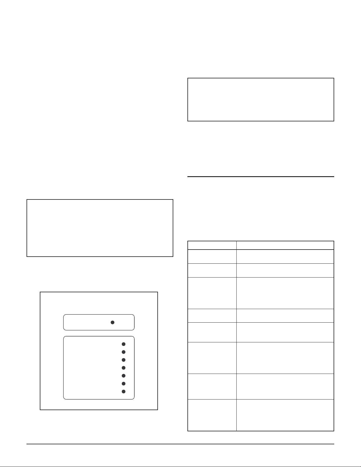
INDICATING PANEL
(Optional)
Figure 2
tions, marked L1 and L2, are on a terminal strip inside
the electrical box. Make connections through the
plugged hole (identified by a tag) on the bottom right of
the box.
DANGER
Ground the dryer using the connection
supplied inside the electrical box.Refer to the
electrical schematic on page 16 for
connection details.
Important Note: Do not switch power to the dryer on
and off via a remote disconnect. To avoid dryer malfunction, power to the unit must be switched on and
off using the switch on the dryer control panel.
INDICATORS
All HRD Series dryers with Compu-Purge control have
indicating panels (Figure 2) on the door of the main
electrical box. These indicators help in monitoring dryer
operation and performance. If the dryer malfunctions,
first check this panel to determine the cause of the problem.
Light Function
Power ON
Variable Purge
Mode
High Inlet Air
Temperature
Dryer Overload
Low Inlet Air
Pressure
Sensor
Malfunction
High Humidity
(optional)
Failure-to-Switch
(optional)
Lights when switch is in “ON” position
and power is supplied to dryer.
Lights when drying cycle is controlled
by the microcomputer.
Lights when inlet air temperature
exceeds 120°F. Excessive inlet air
temperature significantly decreases
drying capacity and may result in
higher dew point.
Lights when inlet dryer load exceeds
dryer ability to maintain dew point.
Lights when inlet air pressure is less
than 65 psig. See Maintenance section
(page 12) for additional information.
Lights when temperature or pressure
sensor sends the microcomputer a
reading which is outside the normal range
of the sensor. See Maintenance section
(page 12) for additional information.
Lights when the high humidity monitor
senses excessive moisture in the outlet
air. High humidity may result when
dryer is slugged with water.
Lights if airflow fails to alternate
between desiccant vessels at
designated switching time. Failure to
switch causes desiccant saturation,
resulting in higher dew point.
4 HRD Series Heatless Dryer with Compu-Purge Control (Bulletin 342)
Additional Indicators and Alarms
Liquid Crystal Digital (LCD) Display (optional)
The LCD display is above the indicating panel on the
main electrical box. It displays “
TURE
” (°F) and “ENERGY SAVINGS” as a percent of
dryer capacity. See Maintenance section on page 12 for
complete description of additional readouts.
Dew Point Monitor (optional)
The monitor is between the vessels beneath the electrical box. It continuously displays outlet pressure dew
point. (Consult the owner’s manual supplied with the
monitor for more information.)
Vessel Pressure Gauges
A gauge mounted on each desiccant vessel indicates
which vessel is onstream and which is regenerating. The
gauge on the onstream vessel indicates operating pressure; the gauge on the regenerating vessel indicates 0
psig.
Audible Alarm (optional)
For high-humidity and failure-to-switch options, alarms
can be wired to include a horn as well as a light.
INLET AIR TEMPERA-
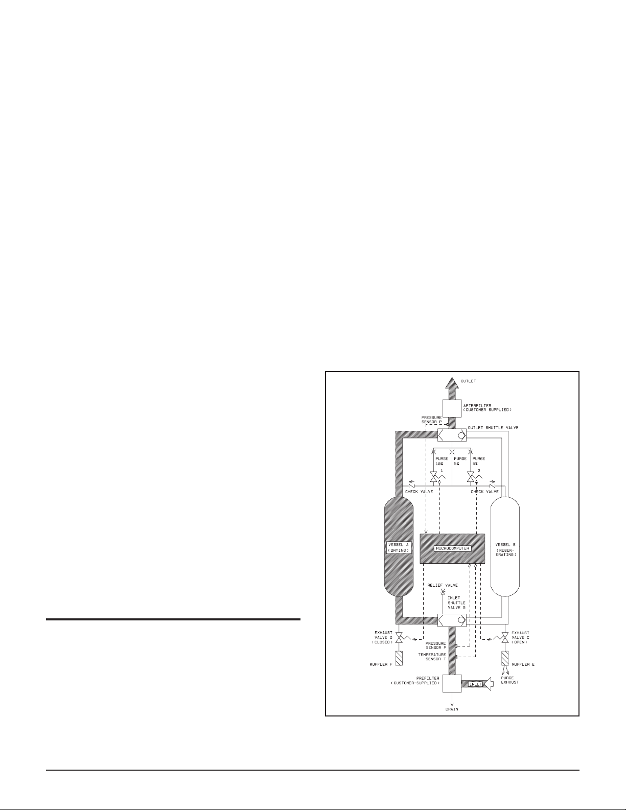
C open and D closed, filtered air enters the inlet shuttle
valve and is directed through vessel A, where moisture
is adsorbed by the desiccant. Dry air exits the vessel,
passes through the outlet shuttle valve and divides into
two streams. The process air passes through the customer-supplied particulate afterfilter and continues to
the process.
A portion of the dried air passes through the purge orifice at approximately atmospheric pressure and passes
downward through vessel B, where it desorbs moisture
from the desiccant. Wet purge air exhausts to the atmosphere through exhaust valve C and muffler E. When
regeneration is complete, exhaust valve C closes and
vessel B is repressurized to dryer operating pressure.
Vessel B is completely regenerated and repressurized,
ready for the next drying cycle.
At the end of the drying period, exhaust valve D opens,
vessel A depressurizes, inlet and outlet shuttle valves
shift, inlet flow switches to vessel B and the drying/regenerating cycle is repeated.
Remote Contacts (optional)
Powered 120 volt, normally open, contacts (1 amp
max.) are furnished to allow hook-up of remote audible
or visible system malfunction alarms. Hook-up contacts
are identified by a tag on the bottom center of the electrical box.
Moisture Indicator (optional)
A color-change moisture indicator is shipped separately
in a moisture-proof bag. The moisture indicator should
be installed at a customer supplied 1¼-inch NPT
threaded port at the dryer outlet. The indicator is green
when dry. The color changes to yellow when the relative humidity of the dryer outlet air is approximately
4%-5%. This indicator is intended only as an inexpensive means of determining possible dryer malfunction.
OPERATION
How It Works
Figure 3 shows the airflow through the dryer with vessel
A drying and vessel B regenerating.
Saturated air enters a customer-supplied prefilter which
separates oil mists, liquid oil, water and particulates
from the airstream. Separated contaminants are discharged through the prefilter drain. With exhaust valve
HRD Series Heatless Dryer with Compu-Purge Control (Bulletin 342) 5
AIRFLOW SCHEMATIC
Figure 3

For standard models designed to provide a –40°F pressure dew point, inlet air continues to flow through one
vessel for half of the standard 10-minute cycle. For
models designed to provide a –100°F pressure dew
point, the standard cycle is 5 minutes.
Compu-Purge Control
Compu-Purge control uses a microcomputer to adjust
the purge airflow rate and drying cycle to automatically
match purge air to the inlet moisture load.
Electronic temperature and pressure sensors continuously track inlet temperature and inlet and outlet pressure and transmit these to the microcomputer. The
microcomputer calculates the dryer load and the most
efficient combination of purge flow rate and duration to
regenerate the moisture adsorbed during the drying period.
able Purge Mode. See Maintenance section (page
12) for additional information.
Start-Up
Once your HRD Series dryer with Compu-Purge control
has been installed according to instructions, it is ready
for start-up.
To start the dryer:
1. Close customer-supplied shutoff valve at dryer inlet.
2. Open customer-supplied bypass valve, if installed.
3. Close customer-supplied letdown and shutoff valves
at dryer outlet.
4. Supply compressed air up to inlet shutoff valve.
Purge flow rate can be varied from 0 to 20% in increments of 5% by purge control valves 1 and 2. Purge duration can also be varied. The optimum combination of
purge control valve openings is automatically selected
by the microcomputer to supply only as much purge air
as needed for complete regeneration.
When the amount of purge air required to regenerate the
desiccant is more than 20% of the inlet flow, the dryer
will operate on a shortened cycle until the overload condition is corrected. For models designed to deliver air at
–40°F pressure dew point, the dryer will operate on a
5-minute cycle when in the Overload Mode. For –100°F
pressure dew point operation, a 3-minute cycle is used.
The microcomputer uses three modes of dryer operation
to match the inlet moisture load:
Compu-Purge Mode – When the microcomputer
adjusts purge air to match dryer load requirements,
the dryer is operating in the Compu-Purge mode.
Standby Mode – When there is low or no demand
for air, the dryer operates in a standby mode: the
dryer purges until the desiccant is regenerated, the
vessels repressurize, then the dryer automatically
shuts down; the dryer purges every 30 minutes to
assure dew point performance.
Fixed-Cycle Mode – If all sensors malfunction, the
“Variable Purge Mode” light will turn off and the
dryer will automatically operate in a fixed cycle
mode, using 15% of the design airflow to regenerate
the offstream vessel. If only one sensor malfunctions, the dryer will default to standard conditions
for that sensor and continue to operate in the Vari-
5. Slowly open inlet shutoff valve and wait for dryer
to reach operating pressure. Pressure gauges on both
dryer vessels will indicate operating pressure.
6. Check all piping connections for air leaks. Remedy
leaks before continuing start-up.
7. Turn on power switch on electrical box.
When power switch is turned on “power on” light
will light. Both vessels will remain at pressure for
up to 60 seconds, then one will depressurize and the
green “Variable Purge” light will light.
Models with LCD display will show in sequence:
DELTECH ENGINEERING, L.P., COPYRIGHT 1988...1991
INLET TEMP. 99° ENERGY SAVINGS = 80%
NO MALFUNCTIONS EXIST
FIRST CYCLE OF OPERATION
USING DEFAULT VALUES
During the next five minutes, the microcomputer
will check itself for any malfunctions. The dryer
will operate in a fixed-cycle mode, using 15%
purge, during start-up.
At the end of this period, dryer operation will be
computer-controlled, the “Variable Purge Mode”
light will be on and the microcomputer will automatically control purge rate to match the dryer load.
Models with LCD display will show:
INLET TEMP XX ENERGY SAVINGS = XX%
NO MALFUNCTION EXISTS
6 HRD Series Heatless Dryer with Compu-Purge Control (Bulletin 342)
 Loading...